Ain Shams University Faculty of Engineering Architectural Department Structural Biomimetic Integration in the Formation of Load-Bearing Skins By Nada Mohamed Mohsen Ibrahim Abd El Fattah B.Sc. Architecture, Ain Shams University, 2010 A thesis Submitted to the Faculty of Engineering in Partial Fulfillment of Requirements for the Degree of Master of Science in Architecture Under Supervision of Dr. Ruby Morcos Associate Professor of Architecture Faculty of Engineering Ain Shams University Prof. Dr. Khaled Mohamed Dewidar Professor of Architecture Faculty of Engineering Ain Shams University Prof. Dr. Mostafa Refaat Ismail Professor of Architecture Faculty of Engineering Ain Shams University Cairo, Egypt 2015
Transcript
Ain Shams University Faculty of Engineering Architectural Department
Structural Biomimetic Integration in the Formation of
Load-Bearing Skins
By Nada Mohamed Mohsen Ibrahim Abd El Fattah
B.Sc. Architecture, Ain Shams University, 2010
A thesis Submitted to the Faculty of Engineering in Partial Fulfillment of
Requirements for the Degree of
Master of Science in Architecture
Under Supervision of
Dr. Ruby Morcos Associate Professor of Architecture
Faculty of Engineering Ain Shams University
Prof. Dr. Khaled Mohamed Dewidar Professor of Architecture Faculty of Engineering Ain Shams University
Prof. Dr. Mostafa Refaat Ismail Professor of Architecture Faculty of Engineering Ain Shams University
Cairo, Egypt 2015
STATEMENT
This thesis is submitted to Ain Shams University for the degree of Master of Science in Architecture.
The work included in this thesis was accomplished by the author at the Department of Architecture, Faculty of Engineering, Ain Shams University, during the period from “2010 to 2015”.
No part of this thesis has been submitted for a degree or a qualification at any other university or institute.
Name: Nada Mohamed Mohsen
Signature:
Date:
BOARD OF EXAMINERS Ain Shams University Faculty of Engineering Architectural Department
Researcher Name: Nada Mohamed Mohsen Ibrahim Thesis Title: “Structural Biomimetic Integration in the
Formation of Load-Bearing Skins” Degree: Master of Science in Architecture
Board Signature Prof. Dr. Ahmed Reda Abdin Professor of Architecture Faculty of Engineering Cairo University
(Examiner)
Prof. Dr. Akram Farouk Mohamed Professor of Architecture Faculty of Engineering Ain Shams University
(Examiner)
Prof. Dr. Khaled Mohamed Dewidar Professor of Architecture Faculty of Engineering Ain Shams University
(Supervisor)
Prof. Dr. Mostafa Refaat Ismail Professor of Architecture Faculty of Engineering Ain Shams University
(Supervisor)
Post Graduate Studies
Approval Stamp The Research was approved on:
/ /
Faculty Council Approval University Council Approval
/ / / /
ACKNOWLEDGEMENTS
First of all, I would like to thank ALLAH for his generosity, blessings and giving me power, health and patience to finish
this piece of work. May He always guide me to help my country and widen my knowledge to serve humanity.
My deepest appreciation and thanks to my dearest kind supervisors and examiners. Words aren’t enough to thank
you for your great support and limitless help. Thank you Dr. Ruby Morcos, Prof. Dr. Khaled Dewidar, Prof. Dr. Mostafa
Refaat, Prof. Dr. Ahmed Reda Abdin, Prof. Dr. Akram Farouk. Nothing could be enough to show my respect and
gratitude.
This thesis is a tiny thank you to my beloved mother Omaima Awad may ALLAH rest her soul in peace, my dear father Mohamed Mohsen and my dear sister Nesreen, for their
limitless support and care.
I sincerely appreciate my dear colleagues in PGESCo Civil Department for their help and constant support in load
calculations: Mona Abd El Wanis and Mohamed El Melligy. I would also like to thank Fab Lab Egypt team for their
support in 3D printing.
Special thanks to my supportive and understanding friends who helped and believed in me: Noha Hussein, Yasser El-
Harmil, Ahmed Lashin, Alaa Ehab, Rim Fahmy, Nouran El Kiki, Samar El Motasem, and PGESCo Architectural
Department Team.
Finally, I would like to express my gratitude to everyone who supported me in bringing this thesis to light.
To my mother You will always be missed. I love you.
Thank you for letting me grow my wings, for letting me fly, for catching when I fall, for letting me stand when I can’t and for
assuring me I can fly again. I soared even higher mom, simple because you believed. Without you, I wouldn’t have the patience
to finish this piece of work. I hope I succeeded in making you feel
happy and proud.
To my father and sister Without you, none of my success would be possible. Your support and unconditional
love and care mean the world to me. I love you.
To Dr. Ahmed Mito Your FEDA talks lecture, 2013, had
inspired me with this thesis idea. May God rest your soul in peace my great
professor.
حيم حمن الر الر بسم هللا
رأ باسم ربك الذي خلق * خلق اإلنسان من علق * ق ا {
وربك األكرم * الذي علم بالقلم * علم اإلنسان ما اقرأ
} لم يعلم ]5-1 :[العلق
i
TABLE OF CONTENTS
1. Biomimetic Design in Architecture ................................................. 1
2.4. New Structuralism .................................................................91
2.5. The Engineering Principles of Biological Systems vs. Classical Engineering .......................................................................94
2.5.1. Architectural Examples Based on Biological Engineering Principles .......................................................................................97
2.5.1.2. The Watercube ...............................................................98
2.5.1.3. Concrete Canopy, Auditorium And Movie Theater In Saint Cyprien ............................................................................101
3. Bones Morphology and Architectural Inspiration ...................... 107
3.1. Human Bones ......................................................................107
3.1.1. Bone Modelling ...............................................................108
3.1.1.1. Wolff’s Law ..................................................................108
3.1.2. Bone as an Engineering Material .....................................110
3.1.4. Femur Bone as an Architectural Inspiration ....................115
3.2. Architectural Projects Inspired By Bones ...........................116
3.2.1. Andres Harris, Bone Inspired Structure ...........................116
iii
3.2.2. Opel GM and Mercedes Benz, Bionic Car ......................118
3.2.3. Freedom of Creation, Trabeculae ....................................120
3.2.4. School of Architecture at Saarland University, The Bowooss Bionic Inspired Research Pavilion ...............................121
3.2.5. Wilfredo Mendez, Bio-Structure Bone-Inspired Building Frame, Puerto Rico ......................................................................122
3.2.6. The Common Structural Features between The Eiffel Tower and the Femur Bone .........................................................127
3.3. Reinforced Concrete Vs. Human Bones ..............................131
3.4. Morphogensis Process Mimicking Technique: Topolgy Optimization ...................................................................................133
3.4.1. Topology Optimization Based Software Examples .........134
5.1.9. Comparison Between the Generated Model and the Case Studies ……................................................................................ 185
5.1.10. 3D Printed Femur Bone Inspired Skin Model …….…...187
Fig. 1.8: Ernst Haeckel, radiolaria. ......................................................16
Fig. 1.9: Design for a monumental entrance to the World exhibition in Paris 1900 by René Binet. ....................................................................16
Fig. 1.10: La Sagrada Família. .............................................................16
Fig. 1.21: Development of geometry and structure of the shells of the Opera house. .........................................................................................25
Fig. 1.22: Comparison of stress in an optimised and a non-optimised fork, Claus Mattheck. ...........................................................................26
Fig. 1.23: Xfrog grown eTrees developed into a truss frame and then as a building frame. ..................................................................................28
Fig. 1.26: Digital tumbleweed grown into a structure for a tall building. ..............................................................................................................29
Fig. 1.27: Silica skeleton of the sponge, Euplectella. ..........................30
Fig. 1.28: Top: Rhino drawings for the Spiral Bridge. Bottom: Spiral Bridge rendered in 3D Studio MAX and superimposed on its site. .....31
Fig. 1.29: Living root bridges, Nongriat village. .................................31
Fig. 1.30: Effect of a smooth and hydrophilic surface in contrast to a structured and hydrophobic one. ..........................................................33
Fig. 1.31: Section through the head region of the femur, the thighbone. ..............................................................................................................34
Fig. 1.32: Model showing direction of pure tension and pressure. ......34
Fig. 1.33: Principle of rearrangement of trabecular bone after change of stress, Claus Mattheck. ....................................................................35
Fig. 1.34: Easy Landing tensegrity sculpture of Kenneth Snelson, 1977, stainless steel, 9x26x20m, collection of the city of Baltimore, Maryland. .............................................................................................37
Fig. 1.36: Tensegrity models of the spine show how vertebrae tensegrity structures mimic vertebras. .................................................38
Fig. 1.37: Part front (left) and part rear (right) view and floor plan of Crystal Palace. ......................................................................................39
Fig. 1.38: Interior view of the Crystal Palace. .....................................40
Fig. 1.39: Giant water lily bottom. .......................................................40
Fig. 1.40: Palazetto dello sport in Rome, Nervi and Vitellozzi, 1957. 41
Fig. 1.41: Palazetto dello sport dome ribs. ...........................................41
Fig. 1.42: 9th of October Bridge in Valencia. ......................................42
Fig. 1.43: Sketch for the 9th of October Bridge. ..................................43
Fig. 1.44: Rib construction of the Casa Mila, Antoni Gaudi, 1905. ....44
Fig. 1.45: TWA Terminal. ...................................................................44
Fig. 1.46: TWA Terminal. ...................................................................45
vii
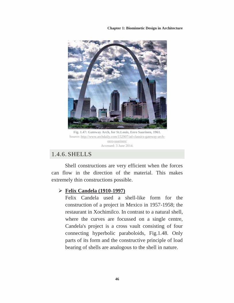
Fig. 1.47: Gateway Arch, for St.Louis, Eero Saarinen, 1961. .............46
Fig. 1.48: Restaurant in Xochimilco, Felix Candela 1958. ..................47
Fig. 1.50: Shape of the inner concrete surface. ....................................47
Fig. 1.51: Centre Pompidou in Metz, France, Shigeru Ban architects, 2010. .....................................................................................................48
Fig. 1.52: Pattern of its wooden gridshell. ...........................................49
Fig. 1.53: Olympia Park in Munich. ....................................................50
Fig. 1.54: Olympia Park. ......................................................................50
Fig. 2.1: The basic families of metals, ceramics, glasses, polymers, and elastomers can be combined in various geometries to create hybrids. 56
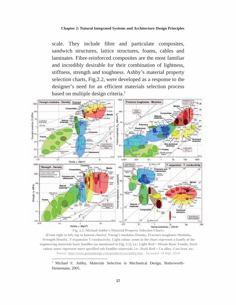
Fig. 2.2: Michael Ashby’s Material Selection Charts. .........................57
Fig. 2.3: Diagram shows the biological systems response categorization. ......................................................................................59
Fig. 2.4: Diagram showing the structural system used by the majority of multi-cellular organisms. .................................................................60
Fig. 2.5: Diagram showing the hierarchical sequence of form generation in nature and architectural traditional design sequence. ....62
Fig. 2.6: Spongy bone tissue. ...............................................................65
Fig. 2.7: Close-up image of spongy bone from the human femur. ......69
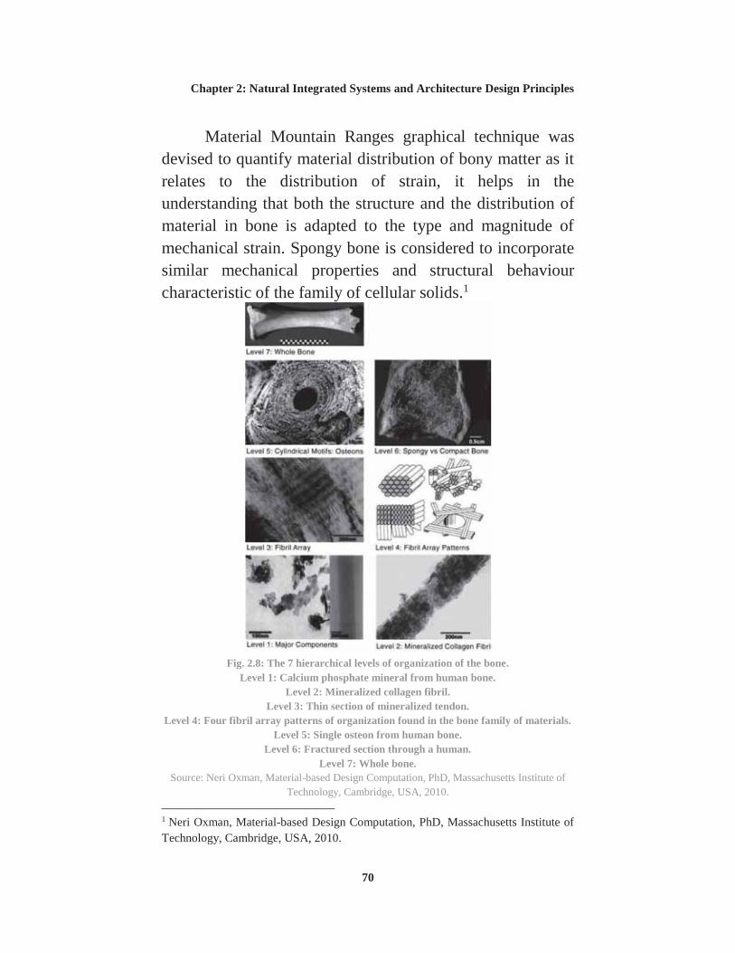
Fig. 2.8: The 7 hierarchical levels of organization of the bone............70
Fig. 2.9: Wood fibres give the wood its anisotropic nature. ................73
Fig. 2.10: 3D models of the internal fibres architecture of a bamboo stem. .....................................................................................................75
viii
Fig. 2.11: Material weighing chart. ......................................................78
Fig. 2.12: Pressure map of the human body form and weight. ............79
Fig. 2.13: Prototype for a Chaise Lounge, 2008, Boston Museum of Science. ................................................................................................80
Fig. 2.14: 3D printed parts illustrating assembly logic. .......................80
Fig. 2.15: Digital model of carpal skin. ...............................................81
Fig. 2.16: Physical model of carpal skin. .............................................82
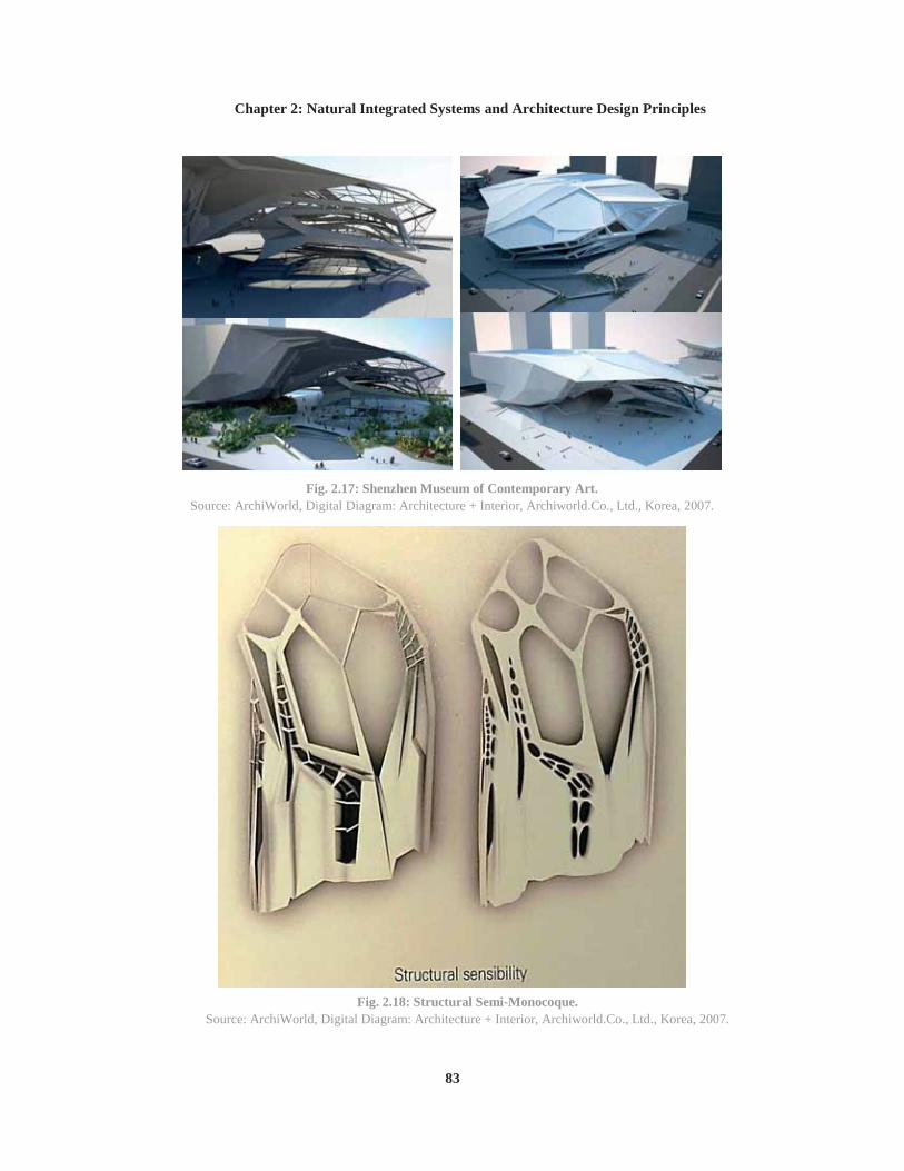
Fig. 2.17: Shenzhen Museum of Contemporary Art. ...........................83
Fig. 2.26: A 3D printed model of an exo-skeleton designed using an equation derived from observations of xylem cells growth. ................88
Fig. 2.27: The diagram starts with a xylem cell scan, converts it into digital model, applies structural forces in a computer simulation, then uses a genetic algorithm to generate and evaluate various possible configurations to find the form with maximum strength and minimum material. ................................................................................................88
Fig. 2.28: Schematic 3D model illustrating multiple variable property representation. ......................................................................................89
Fig. 2.29: Development of the structure and geometry of the shells for the Sydney Opera House. .....................................................................93
Fig. 2.30: SMO Architektur and Arup, Bubble High-rise, Berlin, 2002. ..............................................................................................................97
Fig. 2.31: Watercube National Swimming Centre. ..............................99
Fig. 2.32: Watercube digital structural model. .....................................99
Fig. 2.34: Watercube digital model of cell cluster. ............................100
Fig. 2.35: Watercube physical prototype cells and ETFE cushions fabricated for the testing of environmental and structural behaviour. ............................................................................................................100
Fig. 2.36: Auditorium And Movie Theater In Saint Cyprien. ............101
Fig. 2.37: Axonometric view of the project. ......................................102
Fig. 2.38: Study Models. ....................................................................102
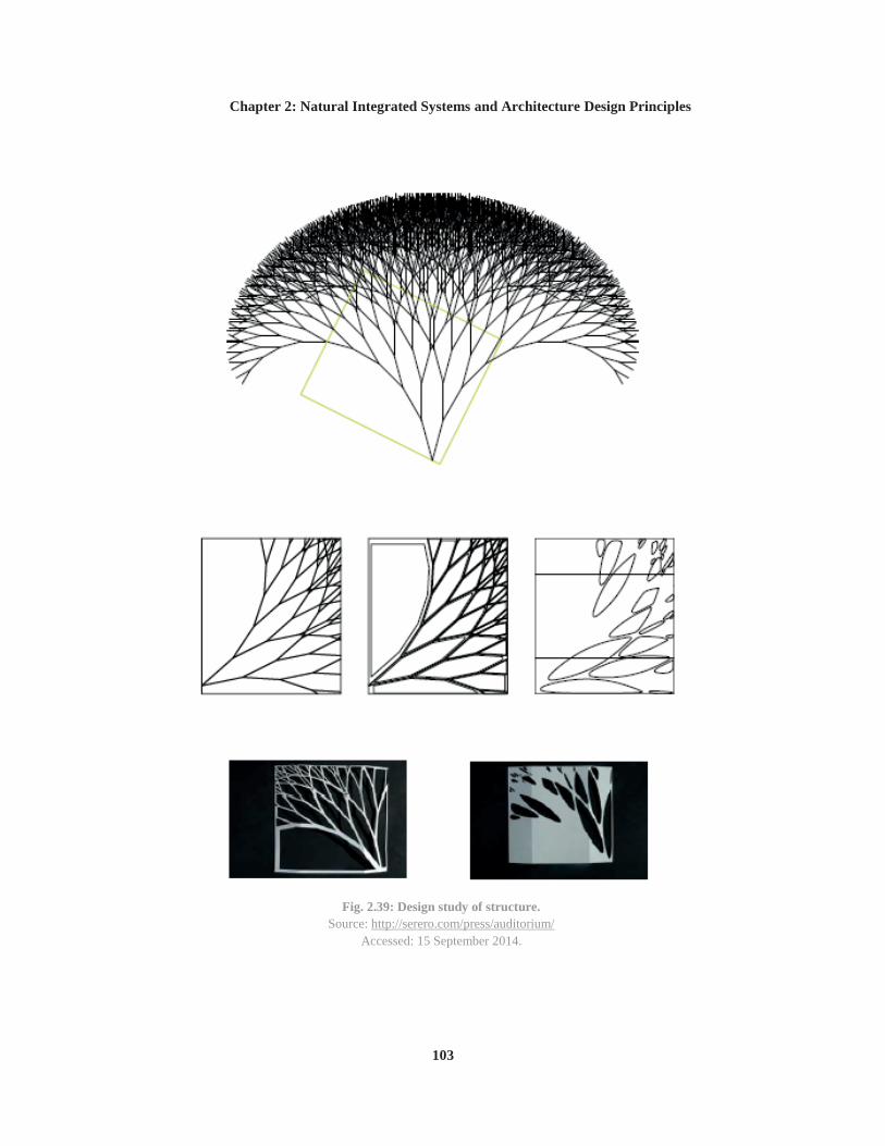
Fig. 2.39: Design study of structure. ..................................................103
Fig. 3.1: Structure of Bone. ................................................................108
Fig. 3.2: Femur Bone Composition. ...................................................108
Fig. 3.3: Wolff's Law explanation, bone adaptation under different mechanical loads. ...............................................................................109
Fig. 3.4: Crane-head and femur..........................................................112
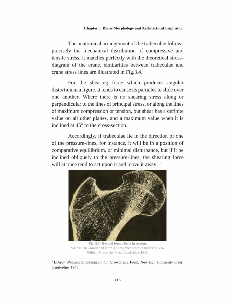
Fig. 3.5: Head of femur bone in section. ............................................113
Fig. 3.6: Forces distribution in femur bone. .......................................114
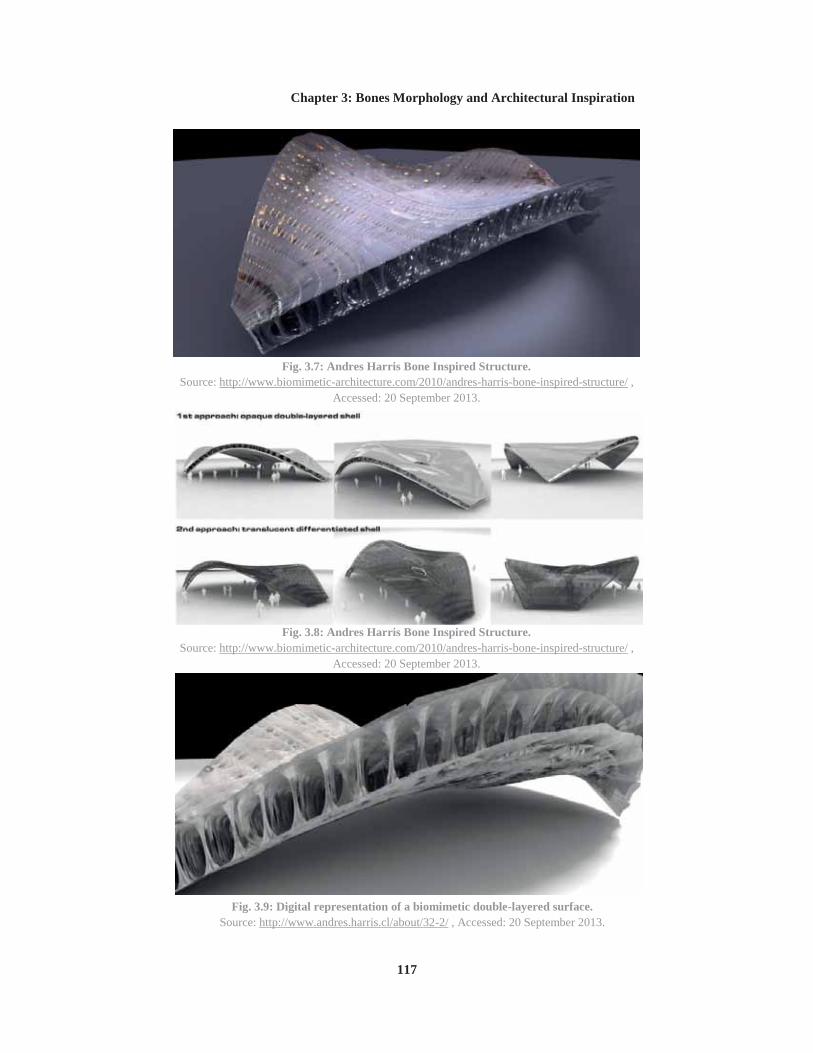
Fig. 3.7: Andres Harris Bone Inspired Structure. ..............................117
Fig. 3.8: Andres Harris Bone Inspired Structure. ..............................117
Fig. 3.9: Digital representation of a biomimetic double-layered surface. ............................................................................................................117
Fig. 3.10: Andres Harris Bone Inspired Structure..............................118
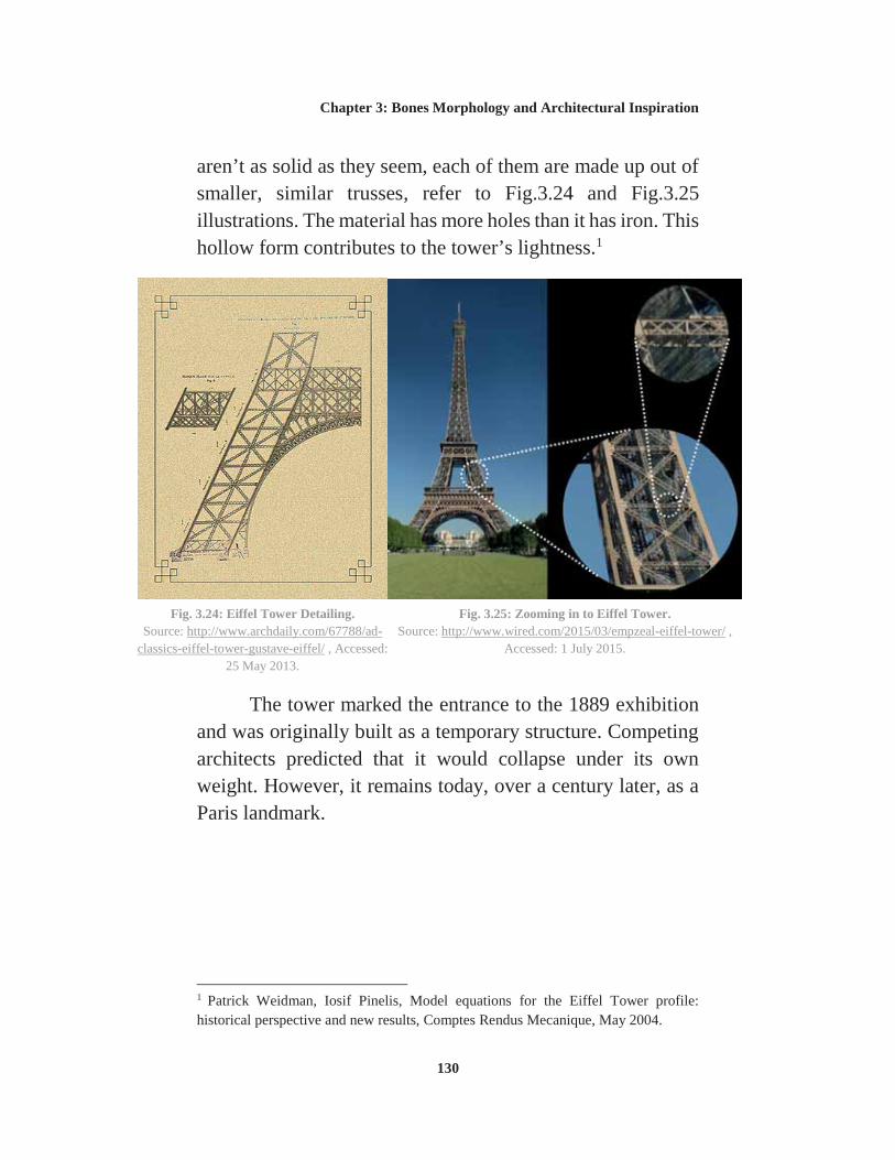
Fig. 3.25: Zooming in to Eiffel Tower. ..............................................130
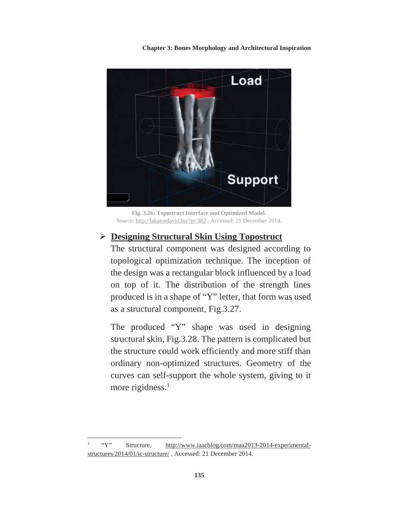
Fig. 3.26: Topostruct Interface and Optimized Model. ......................135
Fig. 3.27: The optimized Y shape. .....................................................136
Fig. 3.28: Structural Skin Drawing Designed by Topostruct. ............136
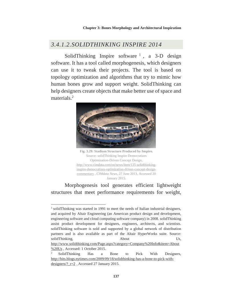
Fig. 3.29: Stadium Structure Produced by Inspire. ............................137
Fig. 3.30: Exoskeleton for Skyscraper Developed in Inspire. ...........138
Fig. 4.1: Classification of tall building structural systems by Fazlur Khan (above: steel; below: concrete). ................................................141
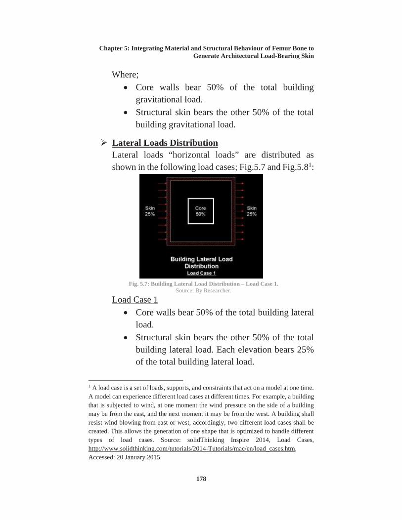
Fig. 5.7: Building Lateral Load Distribution – Load Case 1. ............178
Fig. 5.8: Building Lateral Load Distribution – Load Case 2. ............179
Fig. 5.9: SolidThinking 3D Model of the Structural Skin..................180
Fig. 5.10: Screen Shot of Running Optimization Parameters. ...........181
Fig. 5.11: Topology slider in the Shape Explorer to add or subtract material from the design space.. .........................................................181
Fig. 5.12: Forces and Supports Distribution. .....................................182
Fig. 5.13: Material Library – Concrete Selection. .............................183
Fig. 5.14: Tension and Compression Analysis. .................................184
Fig. 5.15: 3D Printed Model. .............................................................187
LIST OF TABLES Table 2.1: Basic shapes of natural forms and their artificial analogies. ..............................................................................................................58
Table 3.1: Reinforced Concrete Vs. Human Bones Material Properties. ............................................................................................................132
Table 3.2: SolidThinking Inspire Vs. Topostruct Software. ..............139
Table 5.1: Femur Bone Inspired Model in Comparison with Urban Hive Building, O-14 Building, and The Broad Museum, from the point of view of Material and Structural Efficiency....................................185
Biomimicry (from bios, meaning life, and mimesis, meaning to imitate) is the study of natural forms, systems and processes in nature in order to find more effective and sustainable ways to design and engineer products, buildings and service systems.1 The way how natural systems operate can be applied to architecture to lessen its environmental impact and to increase its efficiency.
Looking at natural structures where it integrates structural efficiency and material optimization to serve their functions, unlike architectural engineering that has traditionally been characterized by the sequential development of ‘form, structure and material’ separately from one another. Compared to nature, our own material strategies appear to be less effective, and mostly wasteful. 2 Where nature utilizes a variety of forms and design methods in its constructions to ensure maximization in terms of structural efficiency while minimizing the required input of material. In nature; the hierarchical sequence in classical architecture ‘form–structure–material’ 3 is inverted bottom-up 4 where the external environment exerts stresses on the developing object and its resulting form is a product of its response to the 1 Janine M. Benyus, Biomimicry; Innovation Inspired by Nature, HarperCollins, 1997. 2 Neri Oxman, Structuring Materiality Design Fabrication of Heterogeneous Materials, Architectural Design Journal AD, The New Structuralism Design, Engineering and Architectural Technologies, Wiley, July/August 2010. 3 Toni Kotnik and Michael Weinstock, Material, Form and Force, Architectural Design Journal AD, Material Computation: Higher Integration in Morphogenetic Design, Wiley, March/April 2012. 4 Neri Oxman, Structuring Materiality Design Fabrication of Heterogeneous Materials, Architectural Design Journal AD, The New Structuralism Design, Engineering and Architectural Technologies, Wiley, July/August 2010.
Introduction
xvi
environment and the limits of the structural properties of the material used.
This thesis discusses the biomimetic inspiration ability to convert the ordinary architectural structures to bio-inspired structures that integrates the structure and material to produce final efficient form. A load-bearing skin will be studied with the above criteria through the study of human bones (Femur Bone) as an inspiration model from both perspectives:
Bone Modelling (Wolff's Law).1 Femur Bone Mechanical Properties.
1 Wolff's law is a theory developed by the German anatomist and surgeon Julius Wolff (1836–1902) in the 19th century that states that bone in a healthy person or animal will adapt to the loads under which it is placed. If loading on a particular bone increases, the bone will remodel itself over time to become stronger to resist that sort of loading. Source: http://en.wikipedia.org/wiki/Wolff%27s_law – Accessed: 31 May 2013.
Introduction
xvii
SUMMARY
Architects and builders have always drawn inspiration from nature. Many analogies can be found in the architecture of all ages, engineers study the examination and application of nature's materials, the structural efficiency of natural forms, natural forms engineering principles, etc. Investigation of the overlaps between architecture and nature is essential in order to reach innovative and efficient structures.
In nature, creation begins with matter, the generation of form becomes a process generated by the physical forces of nature. Material is not considered as a subordinate attribute of form, but rather as its originator. Nature have the ability to gradually distribute material properties according to the acting forces, such as the bone’s ability to remodel under mechanical loads. Where the final form is the diagram of the forces acting on it.
One of the inspiring biological structures is the femur bone. For its material and structural engineering principles that help achieving better material and structural performance. Lots of architects and artists studied its growth and mechanical behaviour to achieve better performing engineering projects. Different biological algorithmic based software is being evolved to help mimicking femur bone properties.
Inspired by natural systems integration, an interest in structure as a generator of form has resulted in load-bearing skin functioning both visually and physically as supportive
Introduction
xviii
elements and surface. 1 Bio-inspired integrated structures (load-bearing skins) produce efficient structures that integrate material optimized distribution and structural behaviour in one envelope.
Combining the above concepts, a case study of a 14 X 22 meters portion of the exterior load-bearing skin was studied from the material and structural efficiency points of comparison applying femur bone properties as an inspiration model. Case study results are compared to its analogies in architectural projects that were designed with the classical engineering principles instead of biological engineering principles. SolidThinking Inspire 2014 software was used for optimization process using its topology optimization tool that mimics bone growth and mechanical properties.
1 Nina Rappaport, Deep Decoration, 30/60/90 Architectural Journal, volume 10, November 2006.
Introduction
xix
PROBLEM DEFINITION
The thesis main problem has emerged after the realization that the dealing with Form, Structure and Material in architectural designs as separate domains from one another has led to inefficient usage of structural materials in architectural designs if compared to natural systems behaviour.1
The integration of Form, Structure and Material in one unique element – Load-bearing Skin – is also called to solve the secondary thesis problem of the usage of substructures and structural elements in the interiors.
Studying the bio-inspired integrated structures can help in solving the above mentioned problems through integrating the material, structure and form to produce an efficient structure that integrates material optimized distribution and structural behaviour in one envelope, releasing interior spaces from structural elements. That will be done through design looking to biology biomimetic approach.
THESIS AIM
Studying and mimicking biological integration of Material, Structure and Form in order to generate an architectural optimized skin that integrates structure and material in one outer envelope.
This will be further examined through the analysis of Femur Bone modelling and mechanical properties and how to 1 Neri Oxman, Structuring Materiality Design Fabrication of Heterogeneous Materials, Architectural Design Journal AD, The New Structuralism Design, Engineering and Architectural Technologies, Wiley, July/August 2010.
Introduction
xx
apply these properties to architecture in order to generate load-bearing structural skin.
Where the main and secondary objectives of the thesis are as follows:
Main Objective: Mimicking nature integrated behaviour (Femur Bone Model) to design structural efficient & material optimized load-bearing skins.
Secondary Objective: Releasing interior spaces from structural members through mimicking nature integration to form one outer envelope that integrates structure & material.
HYPOTHESIS
Studying and applying Femur Bone mechanical properties and its growth behaviour to architecture will help in generating an integrated structural skin that achieves the following;
Optimized material usage. Structural efficiency (Strength and low weight). Structural liberation of interior spaces.
LIMITATIONS
This thesis does not deal with the cultural implications of what the physical appearance of biomimetic integrated architecture should be or what cultural values it should reflect. This thesis focuses on this form of architecture because it is believed that the bio-inspired principles proposed in this
Introduction
xxi
thesis are a significant improvement over current design approaches in architecture.
THESIS METHODOLOGY
The methods that will be used for this thesis are diverse, they are as follows:
Literature Review. Analytical Study. Comparative Analysis.
Through literature review, analytical study and comparative analysis, this thesis is an attempt to establish a design method to generate structural skin that is inspired by femur bone engineering properties through the usage of topology optimization algorithm. A comparative case study is analysed in order to evaluate the validity of the application of such approach by comparison with the conventional architectural engineering design means.
The thesis starts by literature review, where it includes an exploration of biomimicry and how it influences architectural design. Analytical study includes the analysis of the difference between nature and architecture design principles, the analysis of femur bone and the architectural inspired projects and analysing the reinforced concrete exterior structures that will be compared to the generated femur bone experimental model. A comparative analysis between the generated femur bone structural skin model and the conventional reinforced concrete structural skins will be provided in order to study the benefits of applying biological systems design concepts over the classical engineering principles.
Introduction
xxii
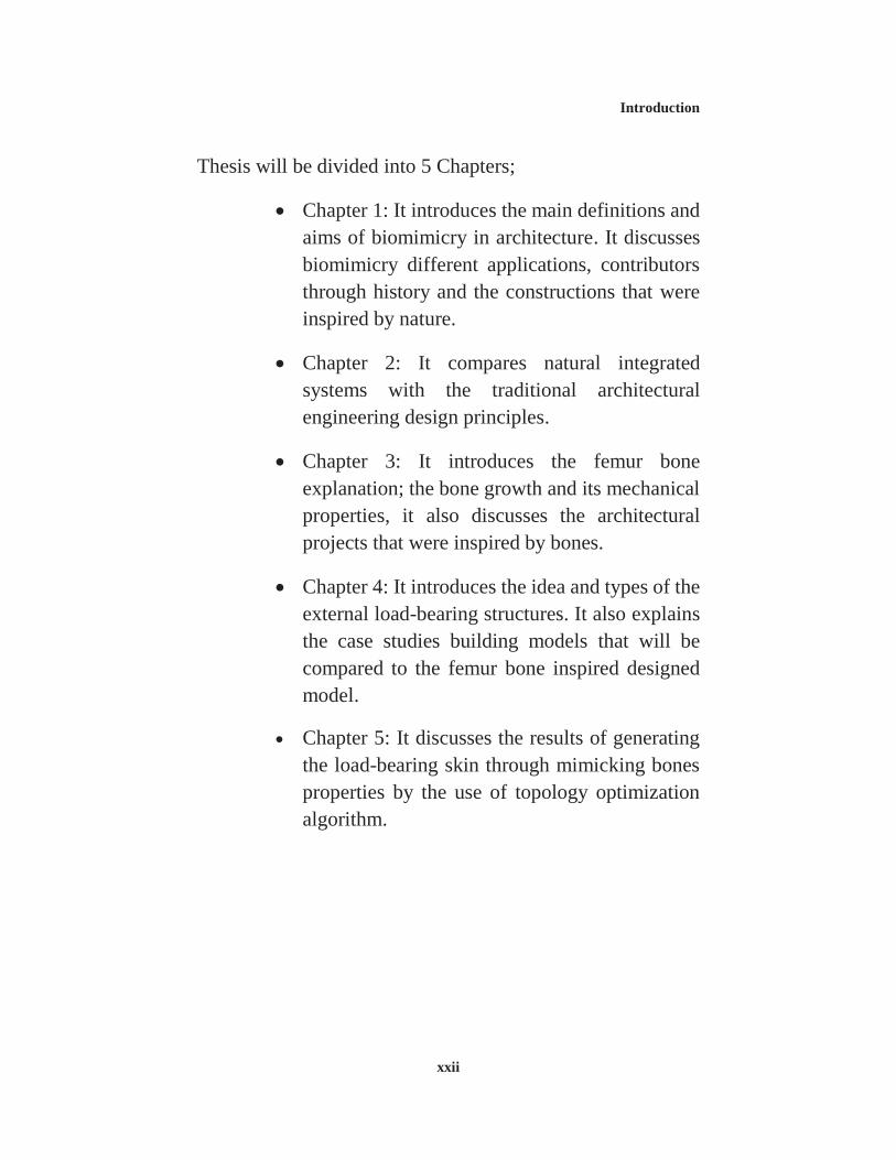
Thesis will be divided into 5 Chapters;
Chapter 1: It introduces the main definitions and aims of biomimicry in architecture. It discusses biomimicry different applications, contributors through history and the constructions that were inspired by nature.
Chapter 2: It compares natural integrated systems with the traditional architectural engineering design principles.
Chapter 3: It introduces the femur bone explanation; the bone growth and its mechanical properties, it also discusses the architectural projects that were inspired by bones.
Chapter 4: It introduces the idea and types of the external load-bearing structures. It also explains the case studies building models that will be compared to the femur bone inspired designed model.
Chapter 5: It discusses the results of generating the load-bearing skin through mimicking bones properties by the use of topology optimization algorithm.
Introduction
xxiii
Fig. 1: Thesis Structure. Source: By Researcher.
• Biomimetic Design in Architecture.Chapter 1
• Natural Integrated Systems andArchitecture Design Principles.Chapter 2
• Bones Morphology and ArchitecturalInspiration.Chapter 3
• Exterior Load-Bearing Structures.Chapter 4
• Integrating Material and StructuralBehaviour of Femur Bone toGenerate Architectural Load-BearingSkin.
Chapter 5
Literature Review
Analytical Study
Analytical Study
Analytical Study
Comparative Analysis
Introduction
xxiv
Table 1: Chapters Structure. Source: By Researcher.
Chapter 1: Biomimetic Design in Architecture
Biomimicry Introduction
Definition
Contributors Through History
Different Biomimicry Applications
Constructions Inspired by Nature
Chapter 2: Natural Integrated Systems and Architecture Design Principles
Natural Integrated Systems
Bones
Bamboo
Palm Trees
Trees New Materiality
New Structuralism The engineering principles of biological systems
The engineering principles of classical engineering
Chapter 3: Bones Morphology and Architectural Inspiration
Human Bones Bones Modelling – Wolff Law Femur Bone
Architectural Projects Inspired By Bones
Morphogensis Process Mimicking Technique: Topolgy Optimization
O-14 Folded Exoskeleton Urban Hive The Broad Museum Fibrous Tower
Chapter 5: Integrating Material and Structural Behaviour of Femur Bone to Generate Architectural Load-Bearing Skin
Methodology
Applying Femur Bone Modelling and Mechanical Properties to Load-Bearing Skins
Final Model Material Optimization Structural Efficiency
CHAPTER 1 BIOMIMETIC DESIGN IN
ARCHITECTURE
“THOSE WHO LOOK TO THE LAWS OF NATURE FOR SUPPORT FOR THEIR NEW WORKS COLLABORATE WITH THE CREATOR. COPIERS DO NOT COLLABORATE. BECAUSE OF THIS, ORIGINALITY CONSISTS IN RETURNING TO THE ORIGIN.” (ANTONI GAUDI)
Chapter 1: Biomimetic Design in Architecture
1
1. BIOMIMETIC DESIGN IN ARCHITECTURE
1.1. INTRODUCTION 1.1.1. BIOMIMCRY DEFINITION
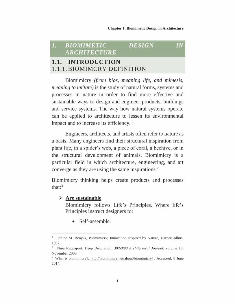
Biomimicry (from bios, meaning life, and mimesis, meaning to imitate) is the study of natural forms, systems and processes in nature in order to find more effective and sustainable ways to design and engineer products, buildings and service systems. The way how natural systems operate can be applied to architecture to lessen its environmental impact and to increase its efficiency. 1
Engineers, architects, and artists often refer to nature as a basis. Many engineers find their structural inspiration from plant life, in a spider’s web, a piece of coral, a beehive, or in the structural development of animals. Biomimicry is a particular field in which architecture, engineering, and art converge as they are using the same inspirations.2
Biomimicry thinking helps create products and processes that:3
Are sustainable Biomimicry follows Life’s Principles. Where life’s Principles instruct designers to:
Self-assemble.
1 Janine M. Benyus, Biomimicry; Innovation Inspired by Nature, HarperCollins, 1997. 2 Nina Rappaport, Deep Decoration, 30/60/90 Architectural Journal, volume 10, November 2006. 3 What is biomimicry?, http://biomimicry.net/about/biomimicry/ , Accessed: 8 June 2014.
Chapter 1: Biomimetic Design in Architecture
2
Optimize rather than maximize. Use energy economically. Embrace diversity. Adapt and evolve. Use life-friendly materials and processes.
By following life principles, more sustainable products and processes can be created.
Perform well In nature, if a design strategy is not effective, its carrier dies. Nature has been trying different strategies for 3.8 billion years. Biomimicry helps the study of the successful strategies of the survivors, so it could be applied to different industries and innovations.
Save energy Energy in the natural world is more expensive than in the human world. Plants have to trap and convert it from sunlight and predators have to hunt and catch it. As a result of the energy shortage, life tends to organize extremely energy efficient designs and systems, optimizing energy use at every turn. Mimicking these efficiency strategies can dramatically reduce the energy consumption.
Cut material costs Nature builds to shape, because shape is cheap and material is expensive. By studying the shapes of nature’s strategies and how they are built, biomimicry can help in minimizing the amount of materials usage while maximizing the effectiveness of the design to achieve its functions.
Chapter 1: Biomimetic Design in Architecture
3
1.1.2. APPROACHES TO BIOMIMICRY
Approaches to biomimicry as a design process typically fall into two categories: Defining a human need or design problem and looking to the ways how other organisms or ecosystems solve similar problems, termed design looking to biology, or identifying a particular characteristic, behaviour or function in an organism or ecosystem and translating that into human designs, referred to as biology influencing design.1
As Janine Benyus defined; there are four areas in which
biomimicry provides the greatest value to the design process (independent of the discipline in which it is integrated):2
Scoping. Discovering. Creating. Evaluating.
Following each phase steps helps ensure the successful integration of life’s strategies into artificial designs.
Design looking to biology The approach where designers look to the living world for solutions, it requires designers to identify problems and then match these problems to organisms that have solved similar issues. This approach is effectively led
1 Maibritt Pedersen Zari, Biomimetic Approaches to Architectural Design for Increased Sustainability, School of Architecture, Paper number: 033, Victoria University, New Zealand, 2007. 2 Biomimicry Thinking, http://biomimicry.net/about/biomimicry/biomimicry-designlens/biomimicry-thinking/ , Accessed: 8 June 2014.
Chapter 1: Biomimetic Design in Architecture
4
by designers identifying initial goals and parameters for the design.1
Design looking to biology approach steps as defined by Janine Benyus and as shown in Fig.1.1 are as follows;2
1. Define context Specify your challenge and its operating conditions.
2. Identify function Determine what key function the design must perform. What does it need to do?
3. Integrate Life’s Principles Incorporating Life’s Principles into the design requirements.
4. Discover natural models Find organisms or ecosystems that have evolved strategies to solve for the needed function.
5. Abstract biological strategies Determine the mechanism behind each organism’s strategy and translate that into a design principle.
1 Maibritt Pedersen Zari, Biomimetic Approaches to Architectural Design for Increased Sustainability, School of Architecture, Paper number: 033, Victoria University, New Zealand, 2007. 2 Biomimicry 3.8., Biomimicry Design Lens: A visual Guide, Biomimicry.net | AskNature.org, 2013.
Fig. 1.1: Design looking to biology steps. Source: Biomimicry 3.8., Biomimicry Design Lens: A visual Guide, Biomimicry.net | AskNature.org, 2013.
Chapter 1: Biomimetic Design in Architecture
5
6. Brainstorm bio-inspired ideas Think of multiple ideas for how to apply the design principles to solve the challenge.
7. Emulate design principles Pick the best ideas from the brainstorming and develop a design concept. Considering aspects of scale, and whether it can go beyond emulating form to also emulate process and ecosystem.
8. Measure using Life’s Principles Assess the design using Life’s Principles as a checklist.
Bionic Car Example An example of such an approach is the prototype Bionic Car by Opel GM and Mercedes Benz. In looking to create a large volume, small wheel base car, the design for the car was based on the boxfish, a surprisingly aerodynamic fish given its box like shape. The chassis and structure of the car are also biomimetic, having been designed using a computer modelling method based upon how trees and bones are able to grow in a way that minimizes stress concentrations and material. The resulting structure looks almost skeletal, Fig. 1.2, as material is allocated only to the places where it is most needed.1
1 Julian F.V. Vincent et al., Biomimetics - its practice and theory, Journal of the Royal Society Interface, April 2006.
Fig. 1.2: Bionic Car, inspired by boxfish, trees and bones. Source: Maibritt Pedersen Zari, Biomimetic Approaches to Architectural Design for Increased Sustainability,
School of Architecture, Paper number: 033, Victoria University, New Zealand, 2007.
Chapter 1: Biomimetic Design in Architecture
6
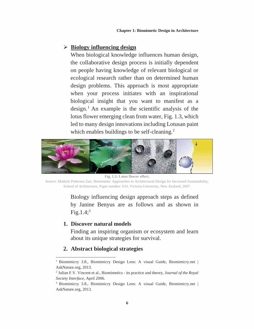
Biology influencing design When biological knowledge influences human design, the collaborative design process is initially dependent on people having knowledge of relevant biological or ecological research rather than on determined human design problems. This approach is most appropriate when your process initiates with an inspirational biological insight that you want to manifest as a design.1 An example is the scientific analysis of the lotus flower emerging clean from water, Fig. 1.3, which led to many design innovations including Lotusan paint which enables buildings to be self-cleaning.2
Biology influencing design approach steps as defined by Janine Benyus are as follows and as shown in Fig.1.4;3
1. Discover natural models Finding an inspiring organism or ecosystem and learn about its unique strategies for survival.
2. Abstract biological strategies 1 Biomimicry 3.8., Biomimicry Design Lens: A visual Guide, Biomimicry.net | AskNature.org, 2013. 2 Julian F.V. Vincent et al., Biomimetics - its practice and theory, Journal of the Royal Society Interface, April 2006. 3 Biomimicry 3.8., Biomimicry Design Lens: A visual Guide, Biomimicry.net | AskNature.org, 2013.
Fig. 1.3: Lotus flower effect. Source: Maibritt Pedersen Zari, Biomimetic Approaches to Architectural Design for Increased Sustainability,
School of Architecture, Paper number: 033, Victoria University, New Zealand, 2007.
Chapter 1: Biomimetic Design in Architecture
7
Determine the mechanism behind the organism’s or ecosystem’s strategy and translate that into a design principle.
3. Identify function Defining what functional need is being met. The function should be the same for both.
4. Define context Specify the circumstances where this function is needed. Who needs to do what this organism or ecosystem is doing?
5. Brainstorm bio-inspired ideas Think of ideas for how to combine the context, function, and design principle to solve a challenge.
6. Integrate Life’s Principles Incorporating Life’s Principles into the solution.
7. Emulate design principles Pick the best ideas from the brainstorming and develop a design concept. Considering aspects of scale, and whether it can go beyond emulating form and also emulate process and ecosystem.
8. Measure using Life’s Principles Assess your design using Life’s Principles as a checklist.
Nature relies on one main source of energy; the solar energy, where:1
It uses only the amount of energy it needs. It matches form to function. It recycles everything. It limits its own internal excesses. It uses constraints as a source of creativity.
Nature integrates variety of forms and design methods in its constructions to ensure maximization in terms of structural efficiency while minimizing the required input of material.
Maximize structural strength Nature employs a relatively small amount of materials in its assemblies as compared to human constructions. However, through unique configurations of these simple materials nature is able to create structures that outperform many man-made structures.
Create high strength-to-weight ratios Since there is competition for material resources within an ecosystem, nature must utilize unique methods of construction that minimize the input of material and usage of energy while maximizing the strength achieved. For example, bones in an organism vary their cross section over their length to deposit material where it is most needed. In addition, cross-linking of the fibres
1 Elodie Ternaux, Industry of Nature, Another Approach to Ecology, Frame Publishers, Amsterdam, 2012.
Chapter 1: Biomimetic Design in Architecture
9
in the bone contribute in maximizing strength without corresponding increase in weight.
Use stress and strain as a basis for structural efficiency The external environment exerts stresses on the developing object and its resulting form is a product of its response to the environment and the limits of the structural properties of the material used.1
1.2. BIOMIMCRY HISTORY
While Buckminster Fuller (1895 - 1983) is often attributed with the early contributions, it is Janine Benyus, a science writer and lecturer on the environment, who is responsible for the recent codification of Biomimicry as a field of research and study. Her 1997 book entitled (Biomimicry: Innovation Inspired by Nature) brought together the recent discoveries in many of disciplines, from engineering to agriculture that can be traced to research and investigations into the designs and processes found in nature. A number of suggestions are put in the book that effectively illustrates the current trends and principles of Biomimetic investigation.2
1 Neal Panchuk, An Exploration into Biomimicry and its Application in Digital & Parametric [Architectural] Design, MSc., University of Waterloo, Waterloo, Ontario, Canada, 2006. 2 Janine M. Benyus, Biomimicry; Innovation Inspired by Nature, HarperCollins, 1997.
Chapter 1: Biomimetic Design in Architecture
10
Nature as Model Biomimicry is a science that studies nature’s models and takes inspiration from their designs and processes to solve human problems.
Nature as Measure Biomimicry uses an ecological standard to judge the rightness of our innovations. After 3.8 billion years of evolution, nature has learned: What works? What is appropriate? What lasts?
Nature as Mentor Biomimicry is a holistic way of viewing and valuing nature. It introduces an era based not on what we can extract from the natural world, but on what we can learn from it.
From a historical standpoint the term biomimetics was introduced in the 1950s by Otto Schmitt (1913 – 1998), an American inventor, engineer and biophysicist who was responsible for developing the field of biophysics and founding the field of biomedical engineering.1
Before the work of Otto Schmitt is that of D’Arcy Thompson (1860 – 1948), a biologist and mathematician who released his book entitled (On Growth and Form) in 1917. This collection of work was instantly recognized for its originality and depth of scope. Often touted as “the first biomathematician”, it was Thompson who suggested that the influences of physics and mechanics on the development of form and structure in organisms were underemphasized. His book illustrate the connection between biological and
1 Janine M. Benyus, Biomimicry; Innovation Inspired by Nature, HarperCollins, 1997.
Chapter 1: Biomimetic Design in Architecture
11
mechanical forms. Thompson’s book does not attempt to posit any type of discovery to biology, nor does he propose a causal relationship between emerging forms in engineering with similar forms in nature. His book presents a description of natural forms and the mathematics that define them. Since its release, the book has served as a wealth of inspiration for biologists, architects, artists and mathematicians.
Robert Le Ricolais (1894-1977) the noted French engineer who taught at University of Pennsylvania from 1954 until 1976, made a career in analyzing natural forms and incorporating their properties into the field of structural design. He revealed that when working with the structure of bone “If you think about the voids instead of working with the solid elements, the truth appears. The structure is composed of holes, all different in dimension and distribution, but with an unmistakable purpose in their occurrence. So we arrive at an apparently paradoxical conclusion, that the art of structure is how and where to put holes. It’s a good concept for building, to build with holes, to show things which are hollow, things which have no weight, which have strength but no weight.”1 Le Ricolais was also fascinated with radiolara, “forms that encompass the properties of both stressed-skin2
and triangulated structures. They are just in between: configurations with multiple holes, a perforated membrane in tension working together with a triangulated frame.”3
1 Robert Le Ricolais, quoted in “Structures, Implicit and Explicit, Interviews with Robert Le Ricolais” VIA 2, University of Pennsylvania, 1973. 2 In mechanical engineering, stressed skin is a type of rigid construction, intermediate between monocoque and a rigid frame, Source: Stressed skin, https://en.wikipedia.org/wiki/Stressed_skin, Accessed: 27 June 2015. 3 Nina Rappaport, Deep Decoration, 30/60/90 Architectural Journal, volume 10, November 2006.
Chapter 1: Biomimetic Design in Architecture
12
Although biomimetics formal introduction as a scientific discipline has been relatively recent, the principles inherent in it as they relate to architecture are derived from a long line of contributors within a variety of biological and architectural streams. 1
1.2.1. CONTRIBUTORS THROUGH HISTORY
Here, some of biomimicry contributors’ work through history will be shown. Starting with plants where they have been used as role models since man began to use technology. Joseph Monier, Simon Schwendener were inspired by plants where they studied its resemblance with architecture and structure. The work of Denis Dollens is also discussed, he focuses his researches on the development of a generative architecture that relies on botany and biomimetics. Also radiolarians have been a source of inspirations for many engineers such as Ernst Haeckel and Robert Le Ricolais. Going through shells, bones and other nature features, the work of Antoni Gaudi, Richard Buckminster Fuller, Jørn Utzon and many others can be explained as their work is based on nature inspiration and mimicking.
Joseph Monier (1823-1906) Joseph Monier, a gardener, made garden pots out of wire mesh and concrete. The fibre structure of decaying parts of paddle cactus and the problem of breaking garden pots inspired him to invent reinforced concrete, Fig.1.5. Monier is considered the inventor of reinforced concrete. He patented his idea in 1867. Reinforced concrete combines the tensile strength of metal and the
1 Petra Gruber, Biomimetics in Architecture: Architecture of Life and Buildings, SpringerWienNewYork, 2011.
Chapter 1: Biomimetic Design in Architecture
13
compression strength of concrete to withstand heavy loads.1
Simon Schwendener (1829-1919) Schwendener, who was both botanist and engineer, has investigated the factor of strength in the cylindrical stem of a plant, Schwendener showed that its strength was concentrated in the little bundles of supportive tissue. In the case figured in Fig.1.6, Schwendener calculated that the resistance to bending was at least 25 times as great as it would have been had the six main bundles been brought close together in a solid core. In
1 Werner Nachtigall, Bionik: Grundlagen und Beispiele für Ingenieure und Naturwissenschaftler, Springer Verlag Berlin Heidelberg, 2002.
2005/concrete/timeline-2009-version.html Accessed: 31 May 2013.
Chapter 1: Biomimetic Design in Architecture
14
many cases the centre of the stem is empty, however in other cases it is filled with soft tissue, suitable for various functions that are unrelated to mechanical support.1
Without any doubt plants construct using the same principles as engineers, but their technology is much finer and more perfect.2 Schwendener found out that in corn stalks, load bearing capacity and bending resistance is achieved with similar elements as in buildings.3
Wladimir Rasdorsky Wladimir Rasdorsky interpreted the construction of plants as composite structure, strands of “sclerenchyma” 4 corresponding to metal reinforcement and the “parenchyma tissue” 5 to the concrete matrix. In 1929 he stated that "there is an extensive analogy between the technical composite structures and the organs of plants concerning the whole construction principle." 6
1 D'Arcy Wentworth Thompson, On Growth and Form, New Ed., University Press, Cambridge, 1945. 2 Werner Nachtigall, Bionik: Grundlagen und Beispiele für Ingenieure und Naturwissenschaftler, Springer Verlag Berlin Heidelberg, 2002. 3 Petra Gruber, Biomimetics in Architecture: Architecture of Life and Buildings, SpringerWienNewYork, 2011. 4 Sclerenchyma provides the main structural support to a plant. Source: Ground tissue, https://en.wikipedia.org/wiki/Ground_tissue , Accessed: 27 June 2015. 5 Parenchyma forms the filler tissue in the soft parts of plants. Source: Ground tissue, https://en.wikipedia.org/wiki/Ground_tissue , Accessed: 27 June 2015. 6 Petra Gruber, Biomimetics in Architecture: Architecture of Life and Buildings, SpringerWienNewYork, 2011.
Chapter 1: Biomimetic Design in Architecture
15
Ernst Haeckel (1834-1919) Ernst Haeckel was both artist and scientist, he ranked among the most famous biologists in the world. Haeckel was fascinated by the diversity of forms that were to be found in marine organisms, especially in the skeletons of radiolarians shown in Fig.1.7.1
The influence of his research and his drawings on architects and designers was considerable. For example, the shapes of radiolaria, Fig.1.8 inspired Rene Binet while working on his project for the world exhibition in Paris 1900,2 Fig.1.9, which is one of the rare examples of the form of a whole organism being translated into the form of a whole building (zoomorphism3).
1 Petra Gruber, Biomimetics in Architecture: Architecture of Life and Buildings, SpringerWienNewYork, 2011. 2 Ernst Haeckel, Olaf Breidbach, Richard Hartmann, Irenäus Eibl-Eibesfeldt, Art Forms in Nature: The Prints of Ernst Haeckel, Prestel, 1998. 3 Zoomorphism takes animal morphology as the role model for architecture projects. Animal representation occurs in three-dimensional imitations of whole or parts of animals, or two dimensional mappings transferred into architecture. Source: Petra Gruber, Biomimetics in Architecture: Architecture of Life and Buildings, SpringerWienNewYork, 2011.
Fig. 1.7: Radiolarians. Source: Petra Gruber, Biomimetics in Architecture:
Architecture of Life and Buildings, SpringerWienNewYork, 2011.
Chapter 1: Biomimetic Design in Architecture
16
Antoni Gaudí (1852 - 1926) Gaudí based his buildings on a simple concept; if nature is the work of God, and if architectural forms are derived from nature, then the best way to honor God is to design buildings based on his work. Antoni Gaudí was a great Spanish architect, he grew up fascinated by geometry and the natural wonders of the Spanish countryside. He stated that "Nothing is art if it does not come from nature." 1
1 The big idea: Biomimetic architecture, Gaudi’s masterpiece, By Jeremy Berlin, http://ngm.nationalgeographic.com/2010/12/big-idea/gaudi-text/1, Accessed: 6 June 2014.
Fig. 1.10: La Sagrada Família. Source: http://www.thenaturelabs.com/article.php?id=55
Accessed: 6 June 2014.
Fig. 1.8: Ernst Haeckel, radiolaria. Source: Petra Gruber, Biomimetics in Architecture: Architecture of Life and
Buildings, SpringerWienNewYork,
Fig. 1.9: Design for a monumental entrance to the World exhibition in Paris 1900 by René Binet.
Source: Petra Gruber, Biomimetics in Architecture: Architecture of Life and Buildings, SpringerWienNewYork, 2011.
Chapter 1: Biomimetic Design in Architecture
17
Sagrada Família1 Begun in 1866, the Sagrada Família in Spain was originally commissioned by the Asociación de Devotos de San José for St Joseph and the holy royal family. Gaudí took inspiration from what he believed to be the direct work of God; the natural world.
One of the most important organic designs in the Sagrada Família is the internal structural support. Gaudí used a vertical structure that mimicked the support and appearance of trees, as shown in Fig.1.11. Naturally, these tree branches supported the weight of leaves; however, for Gaudí’s cathedral, they would be responsible for holding up the canopy of art that covered the ceiling. In addition, this method of support allowed the weight of the stone roof to be more evenly distributed by having multiple supporting branches off of the main column.
1 Ben Orman, Art Nouveau & Gaudí: The Way of Nature, JCCC Honors Journal, Volume 4, Issue 1, Article 2, 2013.
Fig. 1.11: Sagrada Família, Interior Support.
Source: Ben Orman, Art Nouveau & Gaudí: The Way of Nature, JCCC
Similarly to the tree-like columns that support the interior of the church, the doorways, were directly influenced by nature. This new style of arch was formed by the visual tendencies of gravity, specifically, the hyperbolic shape. To find the shape that would be the most natural, Gaudí attached bags of lead in a symmetrical pattern to a rope. He then hung the rope against a wall with the ends fastened to the wall. The resulting shape, a hyperbole, was how Gaudí chose to shape the doorways in the Sagrada Família, Fig.1.12, and many of his other works.
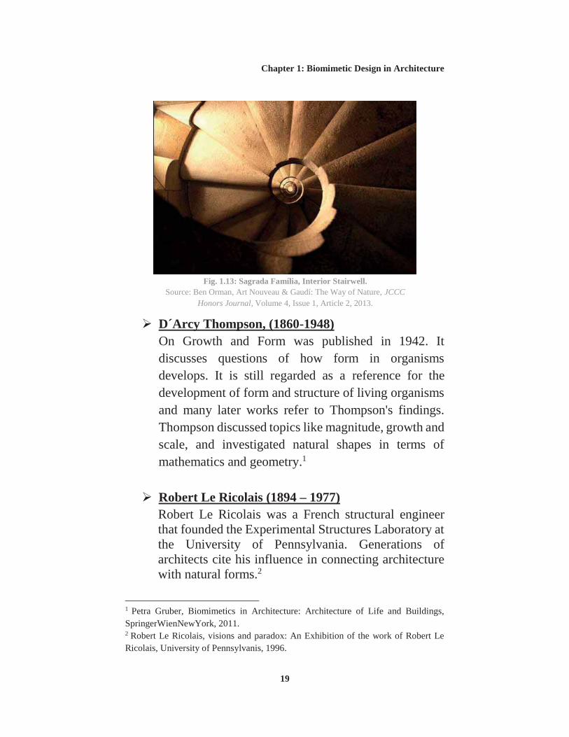
An element that was frequently used throughout Gaudí’s work was the helix. Seen in nature in the shape of snail’s shells, this cylindrical spiral was used in a variety of manners for decoration. This shape was frequently used to form stairways, as exemplified in the Sagrada Família, Fig.1.13. Gaudí repeatedly observed the pattern of falling maple-seed pods and chose to model the staircase after this motion.
Fig. 1.12: Sagrada Família, Interior Support Arches.
Source: Ben Orman, Art Nouveau & Gaudí: The Way of Nature, JCCC
D´Arcy Thompson, (1860-1948) On Growth and Form was published in 1942. It discusses questions of how form in organisms develops. It is still regarded as a reference for the development of form and structure of living organisms and many later works refer to Thompson's findings. Thompson discussed topics like magnitude, growth and scale, and investigated natural shapes in terms of mathematics and geometry.1
Robert Le Ricolais (1894 – 1977) Robert Le Ricolais was a French structural engineer that founded the Experimental Structures Laboratory at the University of Pennsylvania. Generations of architects cite his influence in connecting architecture with natural forms.2
1 Petra Gruber, Biomimetics in Architecture: Architecture of Life and Buildings, SpringerWienNewYork, 2011. 2 Robert Le Ricolais, visions and paradox: An Exhibition of the work of Robert Le Ricolais, University of Pennsylvanis, 1996.
Fig. 1.13: Sagrada Família, Interior Stairwell. Source: Ben Orman, Art Nouveau & Gaudí: The Way of Nature, JCCC
He stated that the ultimate goal for light structures is zero weight, infinite span1, he professed that he had found no better discipline in this unpredictable problem of form than to observe the structures created by nature. Le Monde wrote that Le Ricolais was “the father of space structures”.
Isoflex System The Isoflex System utilizes crosswise layers of corrugated material to form structural panels and tubes. Le Ricolais employed this concept to design an optimized columns, called “Automorphic Tubes”. These structures were comprised of inner and outer layers of parallel compressive tubes bound by a network of tensile diagonals, shown in Fig.1.14, essentially a space frame wrapped in the form of a hollow cylinder. When compared with plain tubes of similar weight and diameter, isoflex system can withstand about 25 % greater axial forces.2
1 Robert Le Ricolais, visions and paradox: An Exhibition of the work of Robert Le Ricolais, University of Pennsylvanis, 1996. 2 Robert Le Ricolais, visions and paradox: An Exhibition of the work of Robert Le Ricolais, University of Pennsylvanis, 1996.
Fig. 1.14: Automorphic Tubes. Source: Robert Le Ricolais, visions and paradox: An Exhibition of the work of Robert Le
Ricolais, University of Pennsylvanis, 1996.
Chapter 1: Biomimetic Design in Architecture
21
Funicular Polygon of Revolution “The Art of Structure is Where to Put the Holes” is a paradox Le Ricolais used to define the strategy of building with things that have strength but no weight. While working with bones structure, Fig.1.16, he stated “that in the search for structures two opposed attitudes are possible: to start with a ‘block’ and work by means of excisions or, on the contrary, to start with a germinal cell in order to arrive at the definitive form by means of addition.”
The idea of the Funicular Polygon of Revolution (FPR) system was to see how we could weave cables and generate a tension network following a minimal surface, by rotating funicular strings around circular compression diaphragms and connecting the tension network to an axial compression member, as shown in Fig.1.15.
Fig. 1.15: Funicular Polygon of Revolution. Source: Robert Le Ricolais, visions and paradox: An
Exhibition of the work of Robert Le Ricolais, University of Pennsylvanis, 1996.
Le Ricolais states “We treated the structural dissymmetry between tension and compression not by following the conventional differentiation of alternating members, common in trusses, but by decomposing the whole structure into two groups acting massively and brought into equilibrium by tensioning.”1
Richard Buckminster Fuller (1895-1983) Richard Buckminster Fuller geodesic domes are optimal for the relationships between volume and weight, efficient use of material and floor area, time needed for erection and demounting, and as a demonstration of liberation from the usage of right angles.
Fuller patented his geodesic domes in 1954. The geometry of the domes is derived from the basic geometry of the icosahedron; a volume with 20 equal faces. The edges are projected onto an inscribed sphere, generating sections of great circles, which are connected to a regular trigonometric pattern, 2 dome geometry is as shown in Fig.1.18.
1 Robert Le Ricolais, visions and paradox: An Exhibition of the work of Robert Le Ricolais, University of Pennsylvanis, 1996. 2 Petra Gruber, Biomimetics in Architecture: Architecture of Life and Buildings, SpringerWienNewYork, 2011.
Fig. 1.17: Montreal Biosphère, 1967, Fuller. Source:
Jørn Utzon (1918 – 2008), Sydney Opera House, 1957 The Danish architect Jørn Utzon won the competition for a new opera house in Sydney in 1957 with a design resembling the arrangement of mussel shells, Fig.1.20. Engineer Ove Arup and Peter Rice were involved in the execution of the project.
The building was to be started soon after the competition. In the competition's design, the curves were drawn by hand, but later the design had to be expressed accurately, through geometry. A range of
variations was thought about, drawn and dismissed, as shown in the development stages sketches in Fig.1.21.
The primary structure consists of identical ribs of reinforced concrete, produced on site. All ribs are great circles of a sphere (the centre of the circles and the sphere are the same - rotation of the circles would create the surface of the sphere). 1
1 Petra Gruber, Biomimetics in Architecture: Architecture of Life and Buildings, SpringerWienNewYork, 2011.
Fig. 1.19: Exhibition model. Source: Petra Gruber, Biomimetics in Architecture: Architecture of Life and
Buildings, SpringerWienNewYork, 2011.
Fig. 1.20: Mussel Shells. Source:
https://seagrant.uaf.edu/news/04ASJ/04.09.04bivalves.html , Accessed: 28 June 2015.
Chapter 1: Biomimetic Design in Architecture
25
Fig. 1.21: Development of geometry and structure of the shells of the Opera house. Development begins from sketch A and ends with sketch M.
Source: Petra Gruber, Biomimetics in Architecture: Architecture of Life and Buildings, SpringerWienNewYork, 2011.
Chapter 1: Biomimetic Design in Architecture
26
Claus Mattheck (1947-Present) Claus Mattheck invented the computer based optimisation procedure SKO (Soft Kill Operation) and CAO (Computer Aided Optimisation), which imitate adaptive growth of trees by technical means.1 Natural trees grow according to the concept of constant stress distribution and thus avoid peaks of tension at forks. During growth, trees add material specifically in tensioned parts. The computer model SKO works the other way: low stress initiates material cutback. CAO is a refined program that can do both: add and cut back material according to the stress distribution in the element. The Opel car company makes use of Mattheck's software in topology optimisation of constructive parts of their designs.2
1 Claus Mattheck, Design in Nature: Learning from Trees, Springer Verlag Berlin Heidelberg, 1998. 2 Werner Nachtigall, Bionik: Grundlagen und Beispiele für Ingenieure und Naturwissenschaftler, Springer Verlag Berlin Heidelberg, 2002.
Fig. 1.22: Comparison of stress in an optimised and a non-optimised fork, Claus Mattheck.
Source: Petra Gruber, Biomimetics in Architecture: Architecture of Life and Buildings,
SpringerWienNewYork, 2011.
Chapter 1: Biomimetic Design in Architecture
27
Dennis Dollens Dennis Dollens is Professor in the Bio-Digital Architectures Program at the Universitat Internacional de Catalunya. He focuses his researches on the development of a generative architecture that relies on botany and biomimetics.1 He uses software as a tool for digital biomimetic extrapolation.2
Xfrog grown eTrees The software he uses is called Xfrog and it’s generally used for landscape architecture. Xfrog generates beautiful, virtually life-like trees, shrubs, and flowers. The software has the ability to produce forms based on botanic algorithms that impart to the digital 3D design, the essence of a growing plant. But these growth perimeters can also be experimented to grow new types of structures based on the same organic algorithms, for example to create a structural truss or new type of column.
Abstract trees that were digitally grew transformed into structures for a building, the trees were programmed to grow into trusses in a rectangular configuration, like that of a multi-story building frame, Fig.1.23.
This process is not a copy of nature, it’s using qualities of a tree’s branches to create a structural unit that could then be digitally exported and
machine fabricated in steel, aluminium, or other types of materials. 1
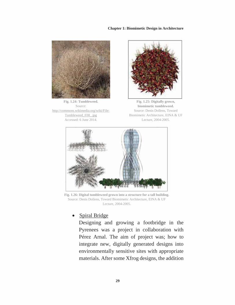
Digital Tumbleweed The tumbleweed is a complex growth of branches with wildly irregular triangulation-like connections on the inside of the plant, creating massive interlocking structural relationships that are held together by barbs. In the form of a ball, the hooked branches make an extremely strong structural truss-like sphere that rolls along fields distributing its seeds, Fig.1.24.
Tumbleweed was used to generate many digital plants, where from which he has further grown a digital building structure that develops from the idea of barbs as connections to create a base of a hypothetical building, shown in Fig.1.26. This design is arrived through a series of Xfrog steps and Rhino digital manipulations that use analog and computational evolution to grow and articulate structural forms.2
Fig. 1.23: Xfrog grown eTrees developed into a truss frame and then as a building frame. Source: Denis Dollens, Architecture, eTrees, & Nature, DISEGNARECON, 2010.
Chapter 1: Biomimetic Design in Architecture
29
Spiral Bridge Designing and growing a footbridge in the Pyrenees was a project in collaboration with Pérez Arnal. The aim of project was; how to integrate new, digitally generated designs into environmentally sensitive sites with appropriate materials. After some Xfrog designs, the addition
Fig. 1.24: Tumbleweed. Source:
http://commons.wikimedia.org/wiki/File:Tumbleweed_038_.jpg Accessed: 6 June 2014.
Source: Denis Dollens, Toward Biomimetic Architecture, EINA & UF
Lecture, 2004-2005.
Fig. 1.26: Digital tumbleweed grown into a structure for a tall building. Source: Denis Dollens, Toward Biomimetic Architecture, EINA & UF
Lecture, 2004-2005.
Chapter 1: Biomimetic Design in Architecture
30
of biomimetic information had took place through the study of: 1
1. Euplectella2: It is made up of microscopic silica spicules that have several different shapes. They incorporated those shapes for elements of the spiral bridge design along with its curves and lattice structure as information from the sponge, Fig.1.27.
2. Tipuana tipu seedpod: They used information from a seedpod common in Barcelona, from the tree Tipuana tipu because of the pod’s spiralling nature as it falls. Depending on wind and other environmental conditions, the pod spirals at different frequencies, and as it comes down it forms graphic information in the form of a spiral.
They used this information to develop the central core of a spiralling structural system. They
1 Denis Dollens, Toward Biomimetic Architecture, EINA & UF Lecture, 2004-2005. 2 Euplectella: A sponge that grows underwater around the Philippines. Source: Denis Dollens, Toward Biomimetic Architecture, EINA & UF Lecture, 2004-2005.
Fig. 1.27: Silica skeleton of the sponge, Euplectella. Source: http://www.nhm.ac.uk/nature-online/species-of-the-day/collections/our-
collections/euplectella-aspergillum/behaviour/index.html Accessed: 6 June 2014.
Chapter 1: Biomimetic Design in Architecture
31
combined ideas from the spiralling seedpod and the Euplectella for the bridge design.
The bridge has a series of intersecting spirals for structural stability, and its rails and walkway provide further structural strength and rigidity. The bridge is a lightweight structure that spirals across the site.
What happens with its shinny metallic surface is a kind of camouflage. The spirals reflect the colors of the trees, light, leaves, sky, and river so they will merge into the environment. They were trying to convey the idea of a rope bridge. It is 20 meters long and 4 meters at its height. The spirals were generated on a modified catenary curve determined by physically hanging a rope from one side of the site to the other then photometrically digitizing the resulting curve.
Fig. 1.28: Top: Rhino drawings for the Spiral Bridge. Bottom: Spiral Bridge rendered in 3D
Studio MAX and superimposed on its site. Source: Denis Dollens, Toward Biomimetic
Architecture, EINA & UF Lecture, 2004-2005.
Fig. 1.29: Living root bridges, Nongriat village. Source:
In the following, some of the classic examples of biomimicry applications will be presented. The examples come from different disciplines and shall illustrate how the biomimicry approach is implemented.
Lotus effect The surface of plants, especially the outer layer of the surfaces of plant leaves, is covered with fine wax excretions, which make the surface hydrophobic. 1 This fine fractal structuring is also responsible for the weak adhesive forces of dirt particles, which can easily be removed with water. This effect is particularly recognized in the leaves of the lotus plant. The botanists Wilhelm Barthlott and Christoph Neinhuis were able to prove that the connection between the structure of the surface, reduced adhesion of particles and hydrophobic character is the key to the self-cleaning mechanism of many biological surfaces. 2 The wetting of surfaces is the basis for the phenomenon. A contact angle of 0° denotes complete wetting, a contact angle of 180° complete non-wetting, Fig.1.30.
1Hydrophobic: Lacking an affinity for water; insoluble in water; repelling water. Source: http://www.biology-online.org/dictionary/Hydrophobic , Accessed: 28 June 2015. 2 Werner Nachtigall, Bionik: Grundlagen und Beispiele für Ingenieure und Naturwissenschaftler,Springer Verlag Berlin Heidelberg, 2002.
Chapter 1: Biomimetic Design in Architecture
33
Plant surfaces lie somewhere in between. On rough surfaces the amount of interface between water and air is increased, where the interface between water and solid surface tends towards a minimum. The water can gain little energy out of adhesion and takes the form of a sphere. The contact angle of the droplet depends only on the surface tension of the liquid.1
The Lotus effect was transferred to products that imitate the effect artificially. Lotusan is the name of paint with self-cleaning characteristics.
Bone Bone is interesting as a role model for architecture, as it represents a natural lightweight construction which helps to fulfil the task of the organism's primary construction. It is also a perfect example for a dynamic adaptable structure. The skeleton is only a part of the whole load bearing structure. Bones work in
1 Werner Nachtigall, Bionik: Grundlagen und Beispiele für Ingenieure und Naturwissenschaftler, Springer Verlag Berlin Heidelberg, 2002.
Fig. 1.30: Effect of a smooth and hydrophilic surface in contrast to a structured and hydrophobic one.
Source: Petra Gruber, Biomimetics in Architecture: Architecture of Life and Buildings, SpringerWienNewYork, 2011.
Chapter 1: Biomimetic Design in Architecture
34
collaboration with tendons and muscles, forming the supporting apparatus.1
As in trees, the concept of constant stress distribution is also valid for bone. There are no predetermined breaking points and there is no waste of material. The principle of economic input of material is important in biological constructions.2
Processes of addition and removal of material are active continuously, adapting the structure of bone to the forces acting. With old age or certain illnesses the dynamic process of adaptation is disturbed, so that the bones become brittle and fragile.
Nature accepts breakage when a certain load limit is exceeded. In case of breakage, the body creates an emergency splint out of fast growing connective tissue. After the fracture is overgrown, the bone is rebuilt to its normal state as well as is possible.
1 Petra Gruber, Biomimetics in Architecture: Architecture of Life and Buildings, SpringerWienNewYork, 2011. 2 Steven Vogel, Cats’ Paws and Catapults: Mechanical Worlds of Nature and People, Norton, 1998.
Fig. 1.32: Model showing direction of pure tension and pressure.
Source: Petra Gruber, Biomimetics in Architecture: Architecture of Life and
Buildings, SpringerWienNewYork, 2011.
Fig. 1.31: Section through the head region of the femur, the thighbone.
Source: Petra Gruber, Biomimetics in Architecture: Architecture of Life and
Buildings, SpringerWienNewYork, 2011.
Chapter 1: Biomimetic Design in Architecture
35
It is known that electrical voltage which is created by bending is responsible for the control of these processes. Piezoelectricity 1 within the bone material creates a grid of excitation, which functions as guidance for the cells transporting the calcium substance. The process of bone growth and degradation is highly dynamic; within days and weeks the strength of human bone can change considerably.2
1 Piezoelectricity is the electric charge that accumulates in certain solid materials (such as crystals, certain ceramics, and biological matter such as bone, DNA and various proteins in response to applied mechanical stress. The word piezoelectricity means electricity resulting from pressure. It is derived from the Greek piezo or piezein, which means to squeeze or press, and electric or electron, which means a source of electric charge. Source: Piezoelectricity, https://en.wikipedia.org/wiki/Piezoelectricity , Accessed: 29 June 2015. 2 Petra Gruber, Biomimetics in Architecture: Architecture of Life and Buildings, SpringerWienNewYork, 2011.
Fig. 1.33: Principle of rearrangement of trabecular bone after change of stress, Claus Mattheck.
Source: Petra Gruber, Biomimetics in Architecture: Architecture of Life and Buildings,
SpringerWienNewYork, 2011.
Chapter 1: Biomimetic Design in Architecture
36
A serious problem with implants is the change of stress distribution. These changes can lead the body to remove bone material in border areas, which loosens the connection of the implanted part. Scientists try to avoid this reaction by using porous material, in which natural material can grow. Elastic bars made of titanium with a plastic coating can mimic the elastic properties of bone. Mimicking the process of creation of bone material is the starting point of many different research groups.
1.4. CONSTRUCTIONS INSPIRED FROM NATURE
1.4.1. TENSEGRITY STRUCTURES
Tensegrity structures are self-stressing. The structure consists of tensioned elements (ropes) creating a continuous subsystem, and elements under compression that create a discontinuous subsystem. The tensile forces are carried by the system itself. The tension is dispersed continuously over all elements of the system. Adopting these structures is difficult for many reasons:
Collapse of a single element leads to total collapse of the structure.
Pre-stressing forces are very high. Assembly is quite complicated. Large and complex design space is needed.
The great advantage of the structures is their efficiency; their remarkable mechanical capacity in relation to the amount of material needed. This mechanical capacity and thus energy related aspect makes the existence of tensegrity
Chapter 1: Biomimetic Design in Architecture
37
structures in nature comprehensible. The construction of vertebrates and the cytoskeleton of cells1 seem to follow the same construction principle, refer to Fig.1.35 and Fig.1.36.
The fact that in spite of their good mechanical characteristics tensegrity structures in architecture are rather rarely applied, suggests that matters of security together with spatial and procedural control are more important in buildings.2
1 The cytoskeleton is the internal structure of the cell. It has been demonstrated that tubulin, one of the components of the cytoskeleton, is stiff, and actin, another component is a tensioner. It uses tensegrity arrays. Source: Donald E. Ingber, Cellular tensegrity: Defining new rules of biological design that govern the cytoskeleton, Journal of Cell Science, 1993. 2 Petra Gruber, Biomimetics in Architecture: Architecture of Life and Buildings, SpringerWienNewYork, 2011.
Fig. 1.34: Easy Landing tensegrity sculpture of Kenneth Snelson, 1977, stainless steel, 9x26x20m, collection of the city of Baltimore, Maryland.
Source: Petra Gruber, Biomimetics in Architecture: Architecture of Life and Buildings, SpringerWienNewYork, 2011.
Fig. 1.36: Tensegrity models of the spine show how vertebrae tensegrity structures mimic vertebras.
Source: http://rsif.royalsocietypublishing.org/content/11/98/20140520 , Accessed: 29 June 2015.
Chapter 1: Biomimetic Design in Architecture
39
1.4.2. GIRDER CONSTRUCTIONS
The easiest method to save material and mass is to distribute loads of the elements onto rib structures of any kind. Connecting thin plates to ribs oriented in the direction of the main stresses is a very economical construction. The support and transfer of loads can happen through a hierarchy of beams. Leaves in nature are very often structured with ribs, 1 John Paxton's Crystal Palace, Fig.1.37 and Fig.1.38, is said to have used the Giant Water Lily as a role model, Fig.1.39. He learned that great horizontal surfaces - whether on a leaf or on a roof - could be supported with the extra rigidity provided by the ribs like configuration. He conceptualized that the ribs and struts that supported the lily would function as the base inspiration of his structures designs.2 1 Petra Gruber, Biomimetics in Architecture: Architecture of Life and Buildings, SpringerWienNewYork, 2011. 2 How a Giant Amazonian Water Lily Changed the Course of Conservatories, http://tanglewoodconservatories.com/blog/how-a-giant-amazonian-water-lily-changed-the-course-of-conservatories/ , Accessed: 1 August 2015.
Fig. 1.37: Part front (left) and part rear (right) view and floor plan of Crystal Palace.
Fig. 1.38: Interior view of the Crystal Palace. Source: http://www.archdaily.com/397949/ad-classic-the-crystal-palace-joseph-
paxton/51d5776db3fc4b5834000230_ad-classic-the-crystal-palace-joseph-paxton_interior-jpg/ Accessed: 2 June 2014.
Fig. 1.39: Giant water lily bottom. Source: https://stonepaths.wordpress.com/tag/victoria-amazonica/ ,
Accessed: 29 June 2015.
Chapter 1: Biomimetic Design in Architecture
41
1.4.3. CURVED SURFACES WITH GIRDERS
Pier Luigi Nervi (1891-1979) Pier Luigi Nervi designed many buildings using this kind of structuring in the 1960s, often inspired from organic forms, following the flow of forces. He became famous for his concrete constructions, halls and stadiums with ribs, crossing or net-like prefabricated concrete elements. "The arrangement of the ribs corresponds to the isostatics of the main points inside a system subject to stress." 1 One of his masterpieces is the Palazetto dello sport in Rome, whose dome is made of fine network resting on V-shaped supports, Fig.1.40, where its configuration has a resemblance to the leaves of the giant Amazon water lily, Fig.1.41.2
1 Paolo Portoghesi, Nature and Architecture, Skira, 2000. 2 A different approach to learning from nature, http://www.architectural-review.com/view/reviews/a-different-approach-to-learning-from-nature/8625697.article , Accessed: 30 June 2015.
Fig. 1.40: Palazetto dello sport in Rome, Nervi and Vitellozzi, 1957.
Fig. 1.41: Palazetto dello sport dome ribs. Source: http://www.archdaily.com/644580/spotlight-
pier-luigi-nervi-2 , Accessed: 30 June 2015.
Chapter 1: Biomimetic Design in Architecture
42
1.4.4. BETWEEN BEAM AND SHELL CONSTRUCTIONS
Santiago Calatrava Calatrava's main works are bridges, buildings for traffic, etc., where his structures designs combine construction with distinct architectural forms. His focus is on the elegant and impressive balancing of masses and forces. In his designs, the dynamic form often overrides functional and constructive requirements. Movement and locomotion as an interesting aspect of Calatrava's work is mostly expressed through form.1
1 Petra Gruber, Biomimetics in Architecture: Architecture of Life and Buildings, SpringerWienNewYork, 2011.
Fig. 1.42: 9th of October Bridge in Valencia. Source: http://structurae.net/structures/data/index.cfm?id=s0000316
Accessed: 2 June 2014.
Chapter 1: Biomimetic Design in Architecture
43
1.4.5. ARCS AND VAULTS
The form of elements should be adapted to the functional requirement, in the case of construction to the flow of forces. The use of parabolic curves for the construction of arcs and vaults was already known in ancient times, discovered by trial and error. By Roman times this knowledge had been lost again, and circular and spherical forms prevailed. Antoni Gaudi, Frei Otto and Heinz Isler made use
Fig. 1.43: Sketch for the 9th of October Bridge. Source: Petra Gruber, Biomimetics in Architecture:
Architecture of Life and Buildings, SpringerWienNewYork, 2011.
Chapter 1: Biomimetic Design in Architecture
44
of catenaries 1 to develop the shape of arcs and vaults in experimental models.2
Eero Saarinen 1910-1961 The famous TWA Terminal at JFK Airport New York, built 1956-1962, has a dynamic and bird-like form. Eero Saarinen said: "...a building in
1 The phenomenon of catenaries: Under the continuous load of its own weight a chain connecting two points will follow a catenary curve - the minimum energy state of the system. Source: Petra Gruber, Biomimetics in Architecture: Architecture of Life and Buildings, SpringerWienNewYork, 2011. 2 Petra Gruber, Biomimetics in Architecture: Architecture of Life and Buildings, SpringerWienNewYork, 2011.
Fig. 1.44: Rib construction of the Casa Mila, Antoni Gaudi, 1905.
Source: http://en.wikipedia.org/wiki/File:LaP
edreraParabola.jpg Accessed: 2 June 2014.
Fig. 1.45: TWA Terminal. Source: http://en.wikipedia.org/wiki/File:Jfkairport.jpg
Accessed: 3 June 2014.
Chapter 1: Biomimetic Design in Architecture
45
which the architecture itself would express the drama and specialness and excitement of travel, a place of movement and transition, The shapes were deliberately chosen in order to emphasize an upward-soaring quality of line. We wanted an uplift." 1
The size and functionality of the interior space no longer meets today's requirements, and only societies for architectural conservation prevented demolition. The expressionist organic form of the building does not promote extension or flexibility of use.2
Eero Saarinen also designed the famous St. Louis gateway arch. This project was built between 1961 and 1966, and has also become cultural heritage. Its steel construction follows a catenary curve, Fig.1.47.
1 TWA Terminal, John F. Kennedy International Airport NY, Eero Saarinen 1962, http://www.galinsky.com/buildings/twa/ , Accessed 3 June 2014. 2 Petra Gruber, Biomimetics in Architecture: Architecture of Life and Buildings, SpringerWienNewYork, 2011.
Fig. 1.46: TWA Terminal. Source: http://www.galinsky.com/buildings/twa/
Accessed: 3 June 2014.
Chapter 1: Biomimetic Design in Architecture
46
1.4.6. SHELLS
Shell constructions are very efficient when the forces can flow in the direction of the material. This makes extremely thin constructions possible.
Felix Candela (1910-1997) Felix Candela used a shell-like form for the construction of a project in Mexico in 1957-1958; the restaurant in Xochimilco. In contrast to a natural shell, where the curves are focussed on a single centre, Candela's project is a cross vault consisting of four connecting hyperbolic paraboloids, Fig.1.48. Only parts of its form and the constructive principle of load bearing of shells are analogous to the shell in nature.
Fig. 1.47: Gateway Arch, for St.Louis, Eero Saarinen, 1961. Source: http://www.archdaily.com/152907/ad-classics-gateway-arch-
eero-saarinen/ Accessed: 3 June 2014.
Chapter 1: Biomimetic Design in Architecture
47
1.4.7. GRID SHELLS
The next step in the minimization of material is to break up the surface of the shell. This is happening with grid shells. Examples of grid shells in architecture are found in vernacular architecture, and also in Frei Otto's work. A recent grid shell project, which also integrated the issue of recycling, is the
Fig. 1.48: Restaurant in Xochimilco, Felix Candela 1958. Source: http://w3.mecanica.upm.es/~pantolin/img/xochimilco.jpg
Accessed: 3 June 2014.
Fig. 1.49: Interior space. Source: Petra Gruber, Biomimetics in Architecture: Architecture of Life and
Buildings, SpringerWienNewYork, 2011.
Fig. 1.50: Shape of the inner concrete surface. Source: Petra Gruber, Biomimetics in
Architecture: Architecture of Life and Buildings, SpringerWienNewYork, 2011.
Chapter 1: Biomimetic Design in Architecture
48
Japanese Pavilion for the Expo 2000 in Hanover, and the Centre Pompidou in Metz, France in 2010.1
Shigeru Ban Shigeru Ban has realized a number of constructions made of paper tubes. The structure of the Expo-hall was developed in collaboration with Frei Otto and Buro Happold civil engineering. The construction combines a series of laminated wood beams with a grid structure of paper tubes, which are simply connected by bands of polyester, Fig.1.51 and Fig.1.52. The cladding consists of a special fire and water resistant paper. The roof of the Centre Pompidou in Metz is based on a hexagonal pattern of laminated wooden units and a fiber glass and teflon membrane, covering a surface area of about 8000m2. 2
1 Petra Gruber, Biomimetics in Architecture: Architecture of Life and Buildings, SpringerWienNewYork, 2011. 2 Petra Gruber, Biomimetics in Architecture: Architecture of Life and Buildings, SpringerWienNewYork, 2011.
Fig. 1.51: Centre Pompidou in Metz, France, Shigeru Ban architects, 2010.
1.4.8. ROPE CONSTRUCTIONS, TENT AND PNEUMATIC CONSTRUCTIONS
The ultimate minimization of material is done with
rope, tent and pneumatic constructions.1
Frei Otto Frei Otto is a pioneer in the field of hanging roof structures. Created by suspending membranes on light steel networks, with column and cable supports, the curving shapes that typified his work were influenced by the forms of spider webs, soap bubbles, trees and skeletons.2 His most famous project is the covering of the Olympia Park in Munich, developed and executed
1 Petra Gruber, Biomimetics in Architecture: Architecture of Life and Buildings, SpringerWienNewYork, 2011. 2 Frei Otto: a life in projects, http://www.dezeen.com/2015/03/11/frei-otto-a-life-in-projects/ , Accessed: 1 August 2015.
Fig. 1.52: Pattern of the wooden gridshell. Source: http://architecturelab.net/shigeru-ban-receives-2014-pritzker-architecture-prize/
Accessed: 3 June 2014.
Chapter 1: Biomimetic Design in Architecture
50
in 1972, Fig.1.53. Membrane buildings belong to the lightest constructions buildable at present. As membranes only transmit tensile forces, the form of these constructions is closely interrelated to the flow of forces.
Otto conceptualized a sweeping tensile structure that would flow continuously over the site imitating the draping and rhythmic protrusions of the Swiss Alps, Fig.1.55. The result is a suspended cloud-like structure that appears to be floating over the site, Fig.1.54.1
1 AD Classics: Munich Olympic Stadium / Frei Otto and Gunther Behnisch, http://www.archdaily.com/109136/ad-classics-munich-olympic-stadium-frei-otto-gunther-behnisch , Accessed: 30 June 2015.
Fig. 1.53: Olympia Park in Munich. Source: http://architecturelab.net/shigeru-ban-
receives-2014-pritzker-architecture-prize/ Accessed: 3 June 2014.
Fig. 1.54: Olympia Park. Source: http://www.archdaily.com/109136/ad-classics-munich-olympic-stadium-frei-otto-gunther-behnisch ,
Accessed: 30 June 2015.
Fig. 1.55: Swiss Alps. Source:
http://www.mountainhikingholidays.com/switzerland_inn-to-inn.htm , Accessed 30 June 2015.
Chapter 1: Biomimetic Design in Architecture
51
1.4.9. FOLDED STRUCTURES
Folding thin plates is another method to gain structural performance without increasing weight. The principle of folding exists in nature; leafs and insect wings, for example have folded veins for reasons of structural support, shown in Fig.1.58 and Fig.1.59. The same principle is applied in architecture in folding structures, Fig.1.56 and Fig.1.57. 1
1 Petra Gruber, Biomimetics in Architecture: Architecture of Life and Buildings, SpringerWienNewYork, 2011.
Fig. 1.57: Folding structure applied on building façade, Future Systems, Oxford Street, London, 2009.
https://commons.wikimedia.org/wiki/File:Sunflower_leaf_structure.jpg , Accessed: 29 June 2015.
Chapter 1: Biomimetic Design in Architecture
53
CONCLUSION:
Biomimetics in the context of architecture do not imply biomorphism 1 only where the mere transfer of form is insufficient to reach the inherent qualities of natural constructions.
Architects and builders have always drawn inspiration from nature. many analogies can be found in the architecture of all ages; the examination and application of nature's materials, the symbolic or structural transfer of natural form, the interrelationship of the building with the environment, all these aspects have been considered by builders at all times. Investigation of the overlaps between architecture and nature is required in order to reach innovative and efficient structures.
"Whenever we talk about biodesign we should simply bear in mind just how amazingly superior a spider's web is to any load-bearing structure man has made – and then derive from this insight that we should look to the superiority of nature for the solutions. If we want to tackle a new task in the studio, then it's best to go outside first and look a t what millennia-old answers there may already be to the problem."2 Luigi Colani.
A comparable analytical study between natural integrated systems engineering principles and architecture will be studied in the next chapter to understand how nature outperform man-made structures.
1 Biomorphism is an art movement that began in the 20th century. It models artistic design elements on naturally occurring patterns or shapes reminiscent of nature and living organisms. Taken to its extreme it attempts to force naturally occurring shapes onto functional devices. Source: http://en.wikipedia.org/wiki/Biomorphism , Accessed: 10 June 2014. 2 http://www.colani.ch/ , Accessed: 10 June 2014.
CHAPTER 2 NATURAL INTEGRATED
SYSTEMS AND ARCHITECTURE DESIGN
PRINCIPLES
“IN HER (NATURE’S) INVENTIONS NOTHING IS LACKING, AND NOTHING IS SUPERFLUOUS.” (LEONARDO DA VINCI)
Chapter 2: Natural Integrated Systems and Architecture Design Principles
54
2. NATURAL INTEGRATED SYSTEMS AND ARCHITECTURE DESIGN PRINCIPLES
2.1. FORM IN NATURE AND FORM IN ARCHITECTURAL DESIGN
In nature, creation begins with matter, the generation of form becomes a process generated by the physical forces of nature. Material is not considered as a subordinate attribute of form, but rather as its originator. On contrary in classical engineering the application of matter becomes opportunistically to any given form. This design methodology assumes unlike nature the predominance of shape over matter in processes of form-generation.
Despite the progress in material science, material has remained inferior to shape across most scales and disciplines of design. Most classical architectural designs have centred on questions relating to material selection rather than questions relating to material generation. The function of materials in design processes appears to be considered and persistently treated as secondary to form itself. 1 In recent years, this tendency has been reinforced by contemporary methods of digital design with its emphasis on NURBS geometry2 within a computational environment, an approach that tends to exclude material from the generative process,
1 Neri Oxman, Material-based Design Computation, PhD, Massachusetts Institute of Technology, Cambridge, USA, 2010. 2 Non-uniform rational basis spline (NURBS) is a mathematical model commonly used in computer graphics for generating and representing curves and surfaces. Source: Non-uniform rational B-spline, https://en.wikipedia.org/wiki/Non-uniform_rational_B-spline , Accessed: 30 April 2015.
Chapter 2: Natural Integrated Systems and Architecture Design Principles
55
leaving the material selection to the later phases of adapting the designed form as a structure in preparation for fabrication and construction.
More recently, digital simulations of physical form-finding experiments - such as the hanging chain models or tensioned membranes originally used by architects and engineers like Antoni Gaudi, Frei Otto or Heinz Isler - have become commonly available. It produces optimised structural forms from a direct relationship between the force flow and the generated form. But neither in digital nor in physical form-finding techniques do material properties play a major defining role in the process; material is merely a subordinate means of tracing the form and making it buildable.1
In nature, an alternative path to the generation of form takes place where the interaction between material properties and their environment is prioritized and thus precedes the resulting shapes. Material behaviour in nature appears to be a priority before the emergence of form.
Giving the material a secondary role in the expression of shape, the consideration of material as shape filler comes as no surprise. A materials-based approach to design, potentially replacing this form syndrome with material sensibility, may be of significant impact in today’s solution to environmental problems.2
1 Toni Kotnik and Michael Weinstock, Material, Form and Force, Architectural Design Journal AD, Material Computation: Higher Integration in Morphogenetic Design, Wiley, March/April 2012. 2 Neri Oxman, Material-based Design Computation, PhD, Massachusetts Institute of Technology, Cambridge, USA, 2010.
Chapter 2: Natural Integrated Systems and Architecture Design Principles
56
2.1.1. MATERIAL SELECTION CHART
In selecting the optimal material for a given function, the engineer must weigh categories such as state, structure, processing techniques, environmental conditions, and applications.1
Michael Ashby’s material selection charts provide the designer and engineer with a highly efficient template of classification. Ashby introduces a design tool for materials selection in engineering. It provides a highly consistent and systematic arrangement of materials, their properties and applications in design. Ashby classifies the family of engineering materials as six families as shown in Fig. 2.1: 2
Family members have a number of features in common such as properties, processing routines, and, often, similar applications. The family of hybrids includes combinations of two or more materials in a pre-determined configuration and
1 D. Michelle Addington, Daniel L. Schodek, Smart Materials and New Technologies: For the Architecture and Design Professions, Architectural Press, 2005. 2 Michael F. Ashby, Materials Selection in Mechanical Design, Butterworth-Heinemann, 2005.
Fig. 2.1: The basic families of metals, ceramics, glasses, polymers, and elastomers can be combined in various
geometries to create hybrids. Source: Michael F. Ashby, Materials Selection in
Mechanical Design, Butterworth-Heinemann, 2005.
Chapter 2: Natural Integrated Systems and Architecture Design Principles
57
scale. They include fibre and particulate composites, sandwich structures, lattice structures, foams, cables and laminates. Fibre-reinforced composites are the most familiar and incredibly desirable for their combination of lightness, stiffness, strength and toughness. Ashby’s material property selection charts, Fig.2.2, were developed as a response to the designer’s need for an efficient materials selection process based on multiple design criteria.1
1 Michael F. Ashby, Materials Selection in Mechanical Design, Butterworth-Heinemann, 2005.
Fig. 2.2: Michael Ashby’s Material Property Selection Charts. (From right to left, top to bottom charts): Young’s modulus-Density, Fracture toughness Modulus,
Strength-Density, T-expansion T-conductivity. Light colour zones in the chart represent a family of the engineering materials basic families (as mentioned in Fig. 2.1), i.e.: Light Red = Metals Basic Family, Dark
colour zones represent more specified sub-families materials, i.e.: Dark Red = Cu alloy, Cast Iron, etc. Source: http://www.grantadesign.com/products/ces/ashby.htm , Accessed: 14 Sept. 2014.
Chapter 2: Natural Integrated Systems and Architecture Design Principles
58
2.2. NATURAL INTEGRATED SYSTEMS 2.2.1. NATURAL FORMS
Nature integrates variety of forms and design methods in its constructions to ensure maximization in terms of structural efficiency while minimizing the required input of material.
Natural structures possess a high level of integration and precision with which they serve their functions. A key distinguishing trait of nature’s designs is its capability to generate complex structures of organic, or inorganic, multifunctional composites such as shells, pearls, corals, teeth, wood, silk, horn, collagen, and muscle fibres.1
The variety of natural forms can be thought of as belonging to a set of basic shapes and structures where each organism use them in different proportions.
Table 2.1: Basic shapes of natural forms and their artificial analogies. Reference: Neal Panchuk, An Exploration into Biomimicry and its Application in Digital &
Parametric [Architectural] Design, MSc., University of Waterloo, Waterloo, Ontario, Canada, 2006.
Basic Shape/Structure
Natural Example Artificial Application
Curved shells Skulls, eggs, exoskeletons.
Domed roofs
Columns Tree trunks, long bones, endoskeletons
Posts
Stones embedded in matrices
Worm tubes Concrete
Corrugated structures (Stiffness without mass)
Scallop shells, cactus plants
Doors, packing boxes, aircraft floors, roofs
1 Neal Panchuk, An Exploration into Biomimicry and its Application in Digital & Parametric [Architectural] Design, MSc., University of Waterloo, Waterloo, Ontario, Canada, 2006.
Chapter 2: Natural Integrated Systems and Architecture Design Principles
59
Spirals Sunflowers, shells, horns of wild sheep, claws of the canary bird
Domed roofs
Parabolic Forms Tardigrade Pneumatic structures
To exist and maintain itself throughout its life, an organism must possess the ability to both sense the external environmental forces acting on it and respond to these forces in a way that minimizes damage and eliminates the need for an investment of unnecessary material and structural reinforcement. The ability of biological organisms and structures to function in this regard can be categorized into two systems as follows:1
1 Neal Panchuk, An Exploration into Biomimicry and its Application in Digital & Parametric [Architectural] Design, MSc., University of Waterloo, Waterloo, Ontario, Canada, 2006.
•The structure has an integrated dynamic abilityto sense one or more variables (strain,temperature, etc.), process the variable, and act,sense, and reprocess to continue theperformance required of the design. Livingbone is a material that is in a constant state ofreformation to accommodate the changes in itsloading.
A closed loop system
•This principle of design is aimed at enhancing toughness, which leads to a mechanical integrity of the system. There is no feedback mechanism but the static structural design is unique.
An open loop system
Fig. 2.3: Diagram shows the biological systems response categorization. Source: Neal Panchuk, An Exploration into Biomimicry and its Application in Digital &
Parametric [Architectural] Design, MSc., University of Waterloo, Waterloo, Ontario, Canada, 2006.
Chapter 2: Natural Integrated Systems and Architecture Design Principles
60
2.2.2. NATURAL ORGANISMS STURCTURAL TYPES
Terrestrial organisms exist in an environment subject to both gravity and atmospheric pressure. Aquatic organisms deal with gravity, although to a lesser extent, as well as water pressure. In order to counteract the forces acting on them as well to maintain their form and possible requirements for locomotion, organisms must utilize a structural organization that can accommodate the acting forces. The structural system used by the majority of multi-cellular organisms can be classified as belonging to one of two types:1
1 Neal Panchuk, An Exploration into Biomimicry and its Application in Digital & Parametric [Architectural] Design, MSc., University of Waterloo, Waterloo, Ontario, Canada, 2006.
Endoskeletons (Internal Structure): Animals with
endoskeletons can grow easily because there are no rigid outside boundaries to their bodies. They are vulnerable to wounding from
the outside, but repair of the living tissue is usually not a problem.
Exoskeletons (External Structure): Exoskeletons are
outside the body and encase it like armor. They are light and very strong, and provide attachment
places for the muscles inside. They protect the body from dehydration, predators, and excessive sunlight.
Fig. 2.4: Diagram showing the structural system used by the majority of multi-cellular organisms. (Endoskeleton and Exoskeleton).
Source: Neal Panchuk, An Exploration into Biomimicry and its Application in Digital & Parametric [Architectural] Design, MSc., University of Waterloo, Waterloo, Ontario, Canada, 2006.
Human Endoskeleton. Crab Exoskeleton.
Chapter 2: Natural Integrated Systems and Architecture Design Principles
61
2.2.3. NATURAL MATERIAL BEHAVIOUR
Compared to manmade materials, many natural materials, particularly in the plant kingdom, mechanically outperform some of the most common materials used by engineers and architects. Woods have strength per unit weight comparable with that of the strongest steels, shell and bone have toughness greater than engineering ceramics, and mature bamboo stalks have slenderness ratios which are remarkable even by the standards of modern engineering.1 Yet Nature’s materials are less than half as dense as many of these artificial materials and are characterized by very low weight.2
Nature have the ability to gradually distribute material properties by way of locally optimizing regions of varied external requirements, such as the bone’s ability to remodel under altering mechanical loads. Where the external environment exerts a pressure on the developing object and its resulting form is a product of its response to the environment and the limits of the structural properties of the material used. 3
Natural structures possess a high level of integration and precision with which they serve their functions. Where the hierarchical traditional architectural sequence (form–structure–material) 4 is inverted bottom-up in nature, as
1 Neri Oxman, Material-based Design Computation, PhD, Massachusetts Institute of Technology, Cambridge, USA, 2010. 2 Karl J. Niklas, Plant Biomechanics: An Engineering Approach to Plant Form and Function, University of Chicago Press, Chicago, 1992. 3 Neal Panchuk, An Exploration into Biomimicry and its Application in Digital & Parametric [Architectural] Design, MSc., University of Waterloo, Waterloo, Ontario, Canada, 2006. 4 Toni Kotnik and Michael Weinstock, Material, Form and Force, Architectural Design Journal AD, Material Computation: Higher Integration in Morphogenetic Design, Wiley, March/April 2012.
Chapter 2: Natural Integrated Systems and Architecture Design Principles
62
material informs structure which, in turn, informs the shape of naturally designed specimens. Such is the case with bones and other cellular structures, the shape and structure of which are directly informed by the materials behaviour from which they are made.1
Biological materials can change their material properties to fit the age or the function of their immediate physiological condition. Hence the mechanical behaviour of any single biological material is defined by multiple properties, not all of which can be maximized, each material is used according to its particular qualities and the types and magnitudes of the mechanical forces it must sustain.2
Many biological materials are made of fibres, their multi-functionality is typically achieved by mapping performance requirements to strategies of material structuring and allocation. The shape of matter is therefore directly linked to the influences of force acting upon it. 3 Material is concentrated in regions of high strength and dispersed in areas 1 Neal Panchuk, An Exploration into Biomimicry and its Application in Digital & Parametric [Architectural] Design, MSc., University of Waterloo, Waterloo, Ontario, Canada, 2006. 2 Neri Oxman, Material-based Design Computation, PhD, Massachusetts Institute of Technology, Cambridge, USA, 2010. 3 Steven Vogel, Comparative Biomechanics: Life's Physical World, Princeton University Press, 2003.
Natural Behaviour Material Structure Form
Architectural Behaviour Form Structure Material
Fig. 2.5: Diagram showing the hierarchical sequence of form generation in nature and architectural traditional design sequence.
Source: Neri Oxman, Material-based Design Computation, PhD, Massachusetts Institute of Technology, Cambridge, USA, 2010.
Chapter 2: Natural Integrated Systems and Architecture Design Principles
63
where stiffness is not required. Nature’s ability to gradually distribute material properties by way of locally optimizing regions of varied external requirements is facilitated by its ability to simultaneously model, simulate and fabricate material structuring.1
Fibres in Nature
Fibres can be seen everywhere in nature, and across multiple scales. Like engineering materials, natural materials can also be grouped into classes the common denominator of which is that all natural materials are made of fibres. They include: 2
1. Natural ceramic and ceramic composites include bone, shell, coral, etc. All are made up of ceramic particles such as hydroxyapatite, calcite or aragonite in a matrix of collagen.
2. Natural polymers and polymer composites include cellulose, silk, collagen, keratin and tendon.
3. Natural elastomers such as skin, muscle, cartilage, resilin, and elastin.
4. Natural cellular materials such as wood, cancellous bone, palm and cork all have low densities because of the high volume fractions of voids they contain.
Fibrous composite structures in nature are used mainly for three functions
1. To introduce and exploit heterogeneity and anisotropy. 2. To modulate the tissue’s physical properties.
1 Neri Oxman, Material-based Design Computation, PhD, Massachusetts Institute of Technology, Cambridge, USA, 2010. 2 Neri Oxman, Material-based Design Computation, PhD, Massachusetts Institute of Technology, Cambridge, USA, 2010.
Chapter 2: Natural Integrated Systems and Architecture Design Principles
64
3. To create functional architectures and shapes through structural hierarchies.
Fibre structure orientation allows for an almost unlimited geometrical variations, it promotes high levels of functional integration through its graduated properties, it supports the matching between material property distribution and continuous load paths, it also allows the possibility of adaptive response, along with optimization strategies for robustness.1
Anisotropy Property in Nature
Anisotropy is the property of being directionally dependent. It implies the heterogeneity of physical and mechanical properties relative to their functions. Wood is a naturally anisotropic material. Its properties vary widely when measured with the growth grain or against it, wood’s strength and hardness will be different for the same sample if measured in differing orientation. The advantage in controlling the directionality of physical and mechanical properties results in highly efficient structures and forms customized to their environment and tailored to support the range of constraints introduced to them by their environment.2
1 In science, the term “robustness” is used to describe a system that can survive extreme external variations. The robust design of natural living systems is not produced by optimization and standardization, but by redundancy and differentiation. Source: Self-organization and Material Constructions, Architectural Design Journal AD, Techniques and Technologies in Morphogenetic Design, Wiley, March/April 2006. 2 Neri Oxman, Material-based Design Computation, PhD, Massachusetts Institute of Technology, Cambridge, USA, 2010.
Chapter 2: Natural Integrated Systems and Architecture Design Principles
65
2.2.4. “MATERIAL – STRUCTURE – FORM” SEQUENCE IN NATURE
Biological organisms have evolved multiple variations of form that should not be thought of as separate from their structure and materials. Such a distinction is artificial. Form, structure and material act upon each other, this behaviour of all three cannot be predicted by analysis of any one of them separately.1
Natural materials develop under load, and the interior structure of biological materials is an evolutionary response. For example, bone tissue gets denser in response to repeated loads in athletic activities. Bone is a cellular solid porous material that has the appearance of mineralised foam, and its interior is a network of very small and complex connected structures, Fig.2.6. When bone becomes less dense, due to age or prolonged inactivity, it is the very
1 Self-organization and Material Constructions, Architectural Design Journal AD, Techniques and Technologies in Morphogenetic Design, Wiley, March/April 2006.
Fig. 2.6: Spongy bone tissue. Bone can be either compact solid or spongy, with solid
bone usually forming the exterior of the bone and spongy tissue forming the interior. The cellular structure is highly differentiated, formed by an
irregular network of (trabecula) or rod-shaped fibrous tissue. The open spaces within the tissue are filled with
bone marrow. Source: Self-organization and Material Constructions,
Architectural Design Journal AD, Techniques and Technologies in Morphogenetic Design, Wiley,
March/April 2006.
Chapter 2: Natural Integrated Systems and Architecture Design Principles
66
small connective material that vanishes, so that the spaces or cells within the bone become larger.1
Nature creates forms and structures according to the requirements of minimum energy. It does so as a response to the forces and loads as it creates a great diversity of forms from basic principles and a few materials.2 D’Arcy Thompson stated that the form of an object is analogous to the diagram of forces defining it.
Multiple functions are negotiated by nature by means of one single material system rather than optimizing its resources for a single objective function. The survival of such systems depends on nature’s ability to manage and promote its ability to maintain itself, as well as satisfying a set of desired mechanical properties such as strength, stiffness, toughness and resistance to impact. 3
There is little emphasis on expensive materials in nature. There are few chemical substances used in animal life, and they are generally constructed using relatively low-performance materials. Success from a design point of view depends not on what they are made of, but rather in how they are made. Structure rather than energy, is the general design principle of nature.4
1 Self-organization and Material Constructions, Architectural Design Journal AD, Techniques and Technologies in Morphogenetic Design, Wiley, March/April 2006. 2 D'Arcy Wentworth Thompson, On Growth and Form, New Ed., University Press, Cambridge, 1945. 3 Neri Oxman, Material-based Design Computation, PhD, Massachusetts Institute of Technology, Cambridge, USA, 2010. 4 Neri Oxman, Material-based Design Computation, PhD, Massachusetts Institute of Technology, Cambridge, USA, 2010.
Chapter 2: Natural Integrated Systems and Architecture Design Principles
67
In dealing with biology from an engineering point of view, Julian Vincent states that wood or leaf for example have obvious structure yet are mostly treated as materials. The resolution to this problem, generally lies in behaviour, when dealing with a material, then it will have the same stiffness in tension, bending and compression in all directions. If it doesn’t, it is structure.1 Materials are typically classified by charted properties such as strength, density, toughness, elongation, electrical resistively and energy content whereas structures are typically classified by behaviour. 2
2.2.5. NATURAL INTEGRATED SYSTEMS EXAMPLES
The structural dynamics of all natural systems are complex and adaptive, and plants in particular manage their structural behaviour in a way that provides new models for engineered structures. Efficiency and optimisation have very different meanings in biological structures, which feature a high degree of redundancy3 and complexity in their material hierarchies.4
Variations in the section and material properties of biological structural members offer very considerable
1 Julian Vincent, Structural biomaterials, Macmillan, London, 1982. 2 James Edward Gordon, The New Science of Strong Materials: Or, Why You Don't Fall Through the Floor, Penguin Books, Harmondsworth, Middlesex, England, 2nd Ed., 1976. 3 In engineering, redundancy is the duplication of critical components or functions of a system with the intention of increasing reliability of the system. Source: Redundancy (Engineering), http://en.wikipedia.org/wiki/Redundancy_%28engineering%29 , Accessed: 20 Aug. 2014. 4 Self-organization and the Structural Dynamics of Plants, Architectural Design Journal AD, Techniques and Technologies in Morphogenetic Design, Wiley, March/April 2006.
Chapter 2: Natural Integrated Systems and Architecture Design Principles
68
advantages over the constant section usually adopted in conventional engineered structures. The differentiated distribution of cells, fibres and bundles, according to height and slenderness, offers a very interesting model for the production of fibre-composite materials systems. Sectional variations produce anisotropy, a gradation of values between stiffness and elasticity along the length of the stem that is particularly useful for resisting dynamic and unpredictable loadings.1
Woods and palms resist bending and buckling, silk stores elastic strain energy, muscle stores and releases elastic strain energy during locomotion, and so on. Such phenomena have significant impact on the designing and the selection of mechanically efficient engineering materials; when considering beams and plates of a given stiffness or strength, or columns of a given buckling resistance, woods, palms and bamboo are among the most efficient materials available.2
2.2.5.1.BONES (CELLULAR SOLIDS)
Cellular biological materials have complex interior structures, self-organised in hierarchies, to produce modularity, redundancy and differentiation3, refer to Fig.2.8. 1 Self-organization and the Structural Dynamics of Plants, Architectural Design Journal AD, Techniques and Technologies in Morphogenetic Design, Wiley, March/April 2006. 2 Neri Oxman, Material-based Design Computation, PhD, Massachusetts Institute of Technology, Cambridge, USA, 2010. 3 The normal process by which a less specialized cell develops or matures to possess a more distinct form and function. For example, a single-celled zygote develops into a multicellular embryo that further develops into a more complex multisystem of distinct cell types of a fetus. The cell size, shape, polarity, metabolism and responsiveness to signals change dramatically such that a less specialized cell becomes more specialized and acquires a more specific role. Source: Cell Differentiation, http://www.biology-online.org/dictionary/Cell_differentiation , Accessed: 20 Aug. 2014.
Chapter 2: Natural Integrated Systems and Architecture Design Principles
69
The foam geometries of cellular materials offer open and ductile structural systems that are strong and permeable, making them an attractive paradigm for developments in material science and for new structural systems in architecture and engineering. Cellular materials are common at many scales in the natural world, for example in the structure of tiny sea creatures, in wood and in bones. They have an internal structure of cells, voids or spaces filled with air or fluids in common, refer to Fig.2.7. 1
The material, structure, and form of bone are all interrelated in its formation and behaviour. Matter is distributed to fit stress paths. The basic building block of the bone family of materials is the mineralized collagen fibril. The structure of skeletal elements is not the only feature which is adapted to the type of mechanical strain. This applies to the same extent for the density distribution of the bony material providing the mechanical strength. The density of spongy bone depends on the magnitude and direction of the loads it experiences.2
1 Self-organization and Material Constructions, Architectural Design Journal AD, Techniques and Technologies in Morphogenetic Design, Wiley, March/April 2006. 2 Neri Oxman, Material-based Design Computation, PhD, Massachusetts Institute of Technology, Cambridge, USA, 2010.
Fig. 2.7: Close-up image of spongy bone from the human femur.
Source: Neri Oxman, Material-based Design Computation, PhD, Massachusetts Institute of
Technology, Cambridge, USA, 2010.
Chapter 2: Natural Integrated Systems and Architecture Design Principles
70
Material Mountain Ranges graphical technique was devised to quantify material distribution of bony matter as it relates to the distribution of strain, it helps in the understanding that both the structure and the distribution of material in bone is adapted to the type and magnitude of mechanical strain. Spongy bone is considered to incorporate similar mechanical properties and structural behaviour characteristic of the family of cellular solids.1
1 Neri Oxman, Material-based Design Computation, PhD, Massachusetts Institute of Technology, Cambridge, USA, 2010.
Fig. 2.8: The 7 hierarchical levels of organization of the bone. Level 1: Calcium phosphate mineral from human bone.
Level 4: Four fibril array patterns of organization found in the bone family of materials. Level 5: Single osteon from human bone.
Level 6: Fractured section through a human. Level 7: Whole bone.
Source: Neri Oxman, Material-based Design Computation, PhD, Massachusetts Institute of Technology, Cambridge, USA, 2010.
Chapter 2: Natural Integrated Systems and Architecture Design Principles
71
2.2.5.2.TREES (FIBRE STRUCTURES)
Trees are the perfect example of systems which have been shaped by the forces of nature, they represent nature’s strategies in regards to the growth, generation, adaptation and preservation of form, Fig.2.9. Natural systems are shaped by the elements surrounding them. The range of loads to which a tree is exposed is wide and it includes forces of various magnitudes and directions, bending moments, torsional moments, and thermal stresses. If the tree is to resist the loads exerted upon it, these loads must be countered by a support applying equally large, but opposed, reaction loads against it.1
Forces Acting on Trees
o Axial Forces The mass of a tree’s branches exerts (by its very own weight) an axial force on its trunk, thus causing compressive stress. The branches cause compression of the trunk in the axial direction resulting in an uniform distribution of compressive stresses. The soil below the tree’s trunk must therefore exert an equally great but opposite force in order to avoid the hypothetical condition in which the post sinks into the soil. As a reaction, axial tensile forces would cause tensile stresses in the post.
o Eccentric Loading When cutting a trunk horizontally, it is rather easy to trace the relative location of branches by
1 Neri Oxman, Material-based Design Computation, PhD, Massachusetts Institute of Technology, Cambridge, USA, 2010.
Chapter 2: Natural Integrated Systems and Architecture Design Principles
72
establishing areas in the section more or less denser with tissue. In the case of eccentric loading, a uniform bending moment may be acting downwards in the entire trunk, compensated by the ground via the roots. Naturally, the bending moment in the side branch will cause much higher bending stresses than in the trunk. In this case, it may become quite apparent that in the central axis within the trunk and the branch neither tensile nor compressive stresses are present. Despite not being fully loaded, this zone within the tree constrains wood capable of bearing load. It is otherwise quite ineffective with regards to bending and thus rather wasteful from a materials perspective. Nature tolerates this deficiency in a tree motionless and anchored in the soil. However in a mobile mammal, it is found that various bones are hollow in the zones where fibres sustain neutral bending. In the animal kingdom it is the case that no material is placed where there is nothing to carry. For example; bones are shaped simply as hollow tubes.
o Lateral Loading Trees loaded laterally on one side by wind become elliptical in the wind direction. If the tree now deposits all its building materials in the zone of highest bending stress. The tree thus forms a non-circular cross-section which is stiffest against the prevailing bending load, and is characterized by smaller stresses than a
Chapter 2: Natural Integrated Systems and Architecture Design Principles
73
uniformly circular cross-section with an identical external bending moment.
o Composite Loading Besides tensile and compressive stresses resulting from axial tension or compression and the bending stresses, there are also the shear stresses. These are stresses acting tangentially in the shear-loaded plane, and prevent the bodies separated by it from sliding on each other.
Fig. 2.9: Wood fibres give the wood its anisotropic nature. By controlling fibre density and direction, material performance can be significantly
Chapter 2: Natural Integrated Systems and Architecture Design Principles
74
2.2.5.3.BAMBOO (FIBRE STRUCTURES)
Bamboo occurs in natural environments with varying stem diameters and a range of heights. Unlike trees, the growth is mainly longitudinal, with proportionally little radial growth. The stem is made up of approximately 50% long cylindrical cells, 40% fibres and 10% hollow fluid-conducting tubes, which have fibres arranged in sheaths and bundles around them. All bamboos show a marked differentiation in the distribution of cells within the stem, both horizontally and vertically. The percentage of fibres is much higher in the outer third of the wall than in the inner, and in the upper part of the stem compared to the lower part. The distribution of fibres and bundles is differentiated according to height and slenderness, so that the upper parts of the stem consist mainly of many smaller bundles with a higher portion of fibres, ensuring that, as the slenderness increases, the material strength increases appropriately to the increased loading stresses of wind. Differentiation offers the potential for variable stiffness and elasticity within the same material.1
Bamboo can grow to heights of up to 30 metres. Though it has a very thin section, it does not buckle as it sways in the wind. The simulations and analysis demonstrated that bamboo tolerates stresses more efficiently than manmade structures, and does so with a minimum of material. Bamboo is an extremely strong fibre, with twice the compressive strength of concrete and roughly the same strength-to-weight ratio of steel in tension.
1 Self-organization and the Structural Dynamics of Plants, Architectural Design Journal AD, Techniques and Technologies in Morphogenetic Design, Wiley, March/April 2006.
Chapter 2: Natural Integrated Systems and Architecture Design Principles
75
Describing bamboo material in engineering terms, it can be found that its design strategies include differentiated distribution of cells, bundles and fibres in a bamboo section to produce anisotropic properties and emergent structural properties, as described in the 3D models in Fig.2.10.
2.2.5.4.PALM TREES (FIBRE STRUCTURES)
Palm trees show a comparable strategy to bamboo in the density and distribution of materials in the stem, and the anatomy of palms is quite different again from that of trees. The palm stem is strongly differentiated, within the stem, density of fibrous bundles is highest towards the outer part of the stem and lower at the centre, and much higher at the base than at the crown. The material differentiation and changing stem diameter along the palm length are responsible for the
Fig. 2.10: 3D models of the internal fibres architecture of a bamboo stem. The model of the internal fibre structure of bamboo aims at reproducing
the non-uniform fibre density across the stem’s cross-section and the differentiation in the size and shape of the fibres.
Source: Self-organization and the Structural Dynamics of Plants, Architectural Design Journal AD, Techniques and Technologies in
Morphogenetic Design, Wiley, March/April 2006.
Chapter 2: Natural Integrated Systems and Architecture Design Principles
76
high capacity of the palm to respond to exceptional dynamic loading.
The folded structure and overall contoured shape of the palm leaf help in maximising collection of both water and sunlight, and contribute to the strength and stability of the leaf. In the simulations of loadings and subsequent analysis, the stresses on the lower edges of the folds were highest, precisely corresponding with distribution of the veins that provide additional stiffening as well as fulfilling their primary role in the management of fluids.
Unlike engineered structures, in natural biological systems there is no single boundary or contour where one component ends and the other begins; fibrous material is continuous right through the joint. In plants there are no joints, thus the zone where the palm leaf joins its stem has to be defined as a morphological change rather than a mechanical change.1
2.3. NEW MATERIALITY
Given nature’s way, which prioritizes the function of structural and environmental performance as the forces shaping matter into shape. The new materiality is proposing that in mimicking nature’s way, materials are to be designed for highly customized functions rather than simply be selected and assigned to preconceived shapes. This requires the transformation from the culture of material selection to
1 Self-organization and the Structural Dynamics of Plants, Architectural Design Journal AD, Techniques and Technologies in Morphogenetic Design, Wiley, March/April 2006.
Chapter 2: Natural Integrated Systems and Architecture Design Principles
77
material design and material allocation according to the forces acting on it design.1
2.3.1. VARIABLE PROPERTY DESIGN (VPD)
Variable property design is a design approach by which to model, simulate and fabricate material assemblies with varying properties designed to correspond to multiple and continuously varied functional constraints. In this approach, material precedes shape, and it is the structuring of material properties as a function of performance that anticipates their form. Theoretical and technical researches in this approach have been termed (material-based design computation). Inspired by nature, the varying of external factors allows material optimization relative to their structural performance.2
Chaise Longue, Neri Oxman, Museum of Science, Boston, Massachusetts
Chaise longue is a single continuous surface acting both as structure and skin; it provides both support and comfort. This design corresponds to nature systems structural, environmental and performance by adapting its thickness, pattern density and stiffness to load, curvature and skin-pressured areas. The technical objective was to analyse the
1 Neri Oxman, Structuring Materiality Design Fabrication of Heterogeneous Materials, Architectural Design Journal AD, The New Structuralism Design, Engineering and Architectural Technologies, Wiley, July/August 2010. 2 Neri Oxman, Structuring Materiality Design Fabrication of Heterogeneous Materials, Architectural Design Journal AD, The New Structuralism Design, Engineering and Architectural Technologies, Wiley, July/August 2010.
Chapter 2: Natural Integrated Systems and Architecture Design Principles
78
VPD as it is applied to the chaise longue using Voronoi cell tessellation algorithm.
The cellular pattern applied to its entirety is designed to increase the ratio of surface area to volume in occupied areas where the body potentially rests. A pressure map study, as shown in Fig.2.12, was conducted that matches the softness and hardness of the cells to support both low and high-pressured areas.1
By analysing anatomical structures that cause concentrated pressures, the chaise becomes softer and flexible where pressure needs to be relieved. The relative volume of each cellular cushion is locally informed by pressure data averaged with values representing structural support and flexibility. Its density is informed by global and local mean curvature values such that denser, smaller cells are organized in areas of steeper curvature whereas larger cells are found in areas of shallow curvature.
1 Neri Oxman, Structuring Materiality Design Fabrication of Heterogeneous Materials, Architectural Design Journal AD, The New Structuralism Design, Engineering and Architectural Technologies, Wiley, July/August 2010.
Fig. 2.11: Material weighing chart. Top of Fig.: Material weighing chart;
The elasticmodulus of each component is defined relative to the comfort level defined by the user and the average
amount of force exerted per unit area. An algorithm then assigns one out of
five materials for physical construction.
Bottom of Fig.: Detail of 3D physical construction. Stiffer materials (distributed in regions under
compression) are dark while softer materials (distributed in regions under
tension) are light. Source: Neri Oxman, Material-based
Design Computation, PhD, Massachusetts Institute of Technology,
Cambridge, USA, 2010.
Chapter 2: Natural Integrated Systems and Architecture Design Principles
79
It is printed from 5 different materials varying in strength and elasticity, refer to Fig.2.11. The surface is composed of assembled 3D printed patches, Fig.2.14, where it simultaneously deposits materials of different properties corresponding to structural and skin-pressure mappings. Stiffer materials are positioned in surface areas under compression and softer, more flexible materials are placed in surface areas under tension. The chaise’s continuous surface adapts to the person using it by matching body load to stiffness in the computational design processes applied before its actual fabrication. Its thickness, pattern density, stiffness and flexibility are modified according to load, curvature, and skin-pressured areas respectively.1
1 Neri Oxman, Material-based Design Computation, PhD, Massachusetts Institute of Technology, Cambridge, USA, 2010.
Fig. 2.12: Pressure map of the human body form and weight. Source: Neri Oxman, Material-based Design Computation, PhD, Massachusetts Institute of Technology, Cambridge,
USA, 2010.
Chapter 2: Natural Integrated Systems and Architecture Design Principles
80
Fig. 2.13: Prototype for a Chaise Lounge, 2008, Boston Museum of Science. The chaise combines nature structural, environmental and performance by adapting
its thickness, pattern density, stiffness and flexibility to load, curvature, and skin-pressured areas. It is patterned with 5 different materials color-coded by elastic moduli. Stiff (darker colored) and soft (lighter colored) materials are distributed
according to the user’s structural load distribution; Soft silicon is located in regions of higher pressure.
Source: Neri Oxman, Material-based Design Computation, PhD, Massachusetts Institute of Technology, Cambridge, USA, 2010.
Fig. 2.14: 3D printed parts illustrating assembly logic. Source: Neri Oxman, Material-based Design Computation, PhD, Massachusetts Institute
of Technology, Cambridge, USA, 2010.
Chapter 2: Natural Integrated Systems and Architecture Design Principles
81
Carpal Skin: Prototype for a Carpel Tunnel Syndrome Splint, Neri Oxman, Museum of Science, Boston, Massachusetts
Similar to the manner by which load or temperature can be plotted and computationally optimized to fit their function, physical pain may also be mapped in the design and production of medical assistive devices such as pain reducing splints. Carpal Skin is a prototype for a treatment glove for carpal tunnel syndrome, Fig.2.15. The syndrome is a medical condition in which the median nerve is compressed at the wrist, leading to weakness in the hand. Night-time wrist splinting is the recommended treatment for most patients before going into carpal tunnel release surgery. The main problem with current glove solutions is their lack of decustomised features in relation to the patient’s distribution of pain. Carpal Skin is a process by which to map the pain profile of a particular patient and distribute hard and soft materials corresponding to the patient’s anatomical and physiological requirements, as described in Fig.2.16. 1
1 Neri Oxman, Structuring Materiality Design Fabrication of Heterogeneous Materials, Architectural Design Journal AD, The New Structuralism Design, Engineering and Architectural Technologies, Wiley, July/August 2010.
Fig. 2.15: Digital model of carpal skin. Local thickness changes correspond to strategic areas across the surface area of the wrist in cushioning and protecting it from hard surfaces as well as allowing for a comfortable grip.
Source: Neri Oxman, Structuring Materiality Design Fabrication of Heterogeneous Materials, Architectural Design Journal AD, The New Structuralism Design, Engineering and Architectural
Technologies, Wiley, July/August 2010.
Chapter 2: Natural Integrated Systems and Architecture Design Principles
82
Shenzhen Museum of Contemporary Art, EMERGENT / Tom Wiscombe, China
The design of Shenzhen museum is based on structural morphologies found in nature, in terms of natural aesthetics and performative characteristics. Giant water lilies were examined for their bio-mathematical logic that includes a network of deep veins underneath their surface that support their wide diameters, Fig.2.20. Water lilies float on water where their overall stability is determined by the depth, number and distribution of these veins. The building structure similarly spreads over architectural surfaces according to force flows, driven by a rule-based system of branching and computational subdivision. Distributing materials according to the type of forces acting on it. 1
Fig. 2.16: Physical model of carpal skin. In this particular prototype, stiff materials constrain the lateral bending motion at
the wrist, and can be identified by the oblique trajectory of dark and stiff materials. Soft materials allow for ergonomic wrist support and comfort through movement.
Source: Neri Oxman, Structuring Materiality Design Fabrication of Heterogeneous Materials, Architectural Design Journal AD, The New Structuralism Design, Engineering
and Architectural Technologies, Wiley, July/August 2010.
Chapter 2: Natural Integrated Systems and Architecture Design Principles
Chapter 2: Natural Integrated Systems and Architecture Design Principles
85
Paris Courthouse, EMERGENT / Tom Wiscombe, Paris
In nature, the dragonfly morphology is a complex result of multiple patterning systems interweaving in response to force flows and material properties. Dragonfly wings consist of two patterns that act together to form a stable structure that optimizes material. Wings robustness behaviour is due to its structural patterns.
The building designed structure is inspired by dragonfly wings that are functional and wildly varied. Dragonfly wings contain two different patterns; rectilinear grid, which provides structural stiffness (beam-action), and the other is a honeycomb pattern, which provides flexibility (membrane-action), refer to Fig.2.23. In the building, these two pattern concepts were implemented in the design in response to the structural diagram and the forces acting on it. Material is allocated following such patterns; rectilinear grid is used where compression is acting, honeycomb pattern is used where tension is acting, shown in Fig.2.22 and Fig.2.24.1 1 ArchiWorld, Digital Diagram: Architecture + Interior, Archiworld.Co., Ltd., Korea, 2007.
Fig. 2.21: Paris Courthouse. Source: ArchiWorld, Digital Diagram: Architecture +
Interior, Archiworld.Co., Ltd., Korea, 2007.
Chapter 2: Natural Integrated Systems and Architecture Design Principles
image.php?large=1&image=25114 , Accessed: 11 July 2015.
Fig. 2.24: Paris Courthouse Section. Source: http://divisare.com/projects/17412-Emergent-Tom-
Wiscombe-Paris-Courthouse , Accessed: 11 July 2015.
Chapter 2: Natural Integrated Systems and Architecture Design Principles
87
Bio-processing, Xylem Cells
Fernan Federici, a plant scientist at Cambridge University, and David Benjamin, an architect at Columbia University, they generated models of the growth of xylem cells that are specialized in transporting water throughout plants. They used patterns in xylem cell growth, Fig.2.25, to solve architectural structural design problems. One goal is to extract the complex behaviours of these cells at the micrometer scale and apply them to architecture at the scale of meters. The team studied the physical constraints of a cell in order to see how its exoskeleton might offer material distribution and optimization solutions for architectural forms. The team generated data sets corresponding to the growth of the xylem cell exo-skeletons, then fed this data into an application called Eureqa. This software then derived a mathematical equation approximating the data. This in turn becomes a tool to create new cell-like forms for architectural applications that optimizes material usage and help in material allocation according to the acting forces design, refer to the describing diagram in Fig.2.27. 1
1 William Myers, Bio Design: Nature, Science, Creativity, Thames & Hudson, London, 2012.
Fig. 2.25: Xylem Cell. Source: http://www.zina-
studio.com/p287402279/h2638DB08 , Accessed: 12 July 2015.
Chapter 2: Natural Integrated Systems and Architecture Design Principles
88
Fig. 2.26: A 3D printed model of an exo-skeleton designed using an equation derived from observations of xylem cells growth.
Source: William Myers, Bio Design: Nature, Science, Creativity, Thames & Hudson, London, 2012.
Fig. 2.27: The diagram starts with a xylem cell scan, converts it into digital model, applies structural forces in a computer simulation, then uses a genetic algorithm to generate and evaluate various possible configurations to find the form with maximum strength and minimum material. Source: William Myers, Bio Design: Nature, Science, Creativity, Thames & Hudson, London, 2012.
Chapter 2: Natural Integrated Systems and Architecture Design Principles
89
2.3.2. FUNCTIONALLY GRADED MATERIALS (FGMs)
The term Functionally Graded Materials (FGMs) was developed in the mid-1980s in Japan in the design of a hypersonic space plane project where a particular combination of materials used would be required to serve the purpose of a thermal barrier capable of withstanding a surface temperature of 2000 K and a temperature gradient of 1000 K across a 10-mm section. 1 The general idea of structural gradients was initially proposed for composites and polymeric materials in 1972 but it was not until the 1980s when actual models investigating the design, fabrication and evaluation of graded structures were proposed.2
1 Neri Oxman, Variable property rapid prototyping, Virtual and Physical Prototyping, Volume 6, Issue 1, 2011. 2 Y.Miyamoto, W. A. Kaysser, and B. H. Rabin, Functionally graded materials: design, processing, and applications, Chapman and Hall, New York, 1999.
Fig. 2.28: Schematic 3D model illustrating multiple variable property representation.
Chapter 2: Natural Integrated Systems and Architecture Design Principles
90
In Material Science, FGM are characterized by the gradual variation in composition and structure over their volume, resulting in corresponding changes of the material’s properties, see Fig.2.28. Functionally graded materials are a new generation of engineering materials characterized by compositional and structural variation across their volume unit, resulting in property changes in the material such as mechanical shock resistance, thermal insulation, etc.1
The basic structural unit of an FGM resembles biological units such as cell and tissues, and is referred to as an element or a material ingredient. Bamboo, shell, tooth and bone are all made up of graded structures consisting of chemical, physical, geometrical and biological material ingredients.2 The concept of FGMs is revolutionary in the areas of material science and mechanics as it allows full integration between material and structural considerations in the final design of structural components. 3
2.3.3. VARIABLE PROPERTY FABRICATION (VPF)
Currently, there are no rapid prototyping technology in architecture that allows for a continuous modification of material properties such as strength, stiffness, density and elasticity as continuous gradients across the surface and volume area of a functional component. Such variations are
1 Y.Miyamoto, W. A. Kaysser, and B. H. Rabin, Functionally graded materials: design, processing, and applications, Chapman and Hall, New York, 1999. 2 Neri Oxman, Variable property rapid prototyping, Virtual and Physical Prototyping, Volume 6, Issue 1, 2011. 3 A. M. Stoneham, J. H. Harding, Invited review: Mesoscopic modelling: materials at the appropriate scale, Materials Science and Technology, Volume 25, Issue 4, 2009.
Chapter 2: Natural Integrated Systems and Architecture Design Principles
91
usually achieved as discrete changes in physical behaviour by printing multiple components with different properties, and assembling them only after the fabrication process has been completed. Such processes result in material waste and lack of functional precision. Variable property fabrication aims at introducing 3D printing technology1 which offers gradation control of multiple materials within one print to save weight and material quantity while reducing energy inputs. The result is a continuous gradient material structure, highly optimized to fit its structural performance with an efficient use of materials, reduction of waste and the production of highly customized features with added functionality.2
2.4. NEW STRUCTURALISM
Compared to nature, our own material strategies appear to be much less effective, and mostly wasteful. Since the industrialized age, the construction industry has been dependent on discrete solutions for distinct functions. 3 Architectural engineering has traditionally been characterized by the sequential development of (form, structure and material). The new structuralism integrates structuring, digital tectonics, materialization, production and the research that makes this integration possible. Where unlike buildings 1 3D printing is any of various processes for making a three-dimensional object of almost any shape from a 3D model or other electronic data source primarily through additive processes in which successive layers of material are laid down under computer control. A 3D printer is a type of industrial robot. Source: 3D Printing, http://en.wikipedia.org/wiki/3D_printing , Accessed: 25 Aug. 2014. 2 Neri Oxman, Structuring Materiality Design Fabrication of Heterogeneous Materials, Architectural Design Journal AD, The New Structuralism Design, Engineering and Architectural Technologies, Wiley, July/August 2010. 3 Neri Oxman, Structuring Materiality Design Fabrication of Heterogeneous Materials, Architectural Design Journal AD, The New Structuralism Design, Engineering and Architectural Technologies, Wiley, July/August 2010.
Chapter 2: Natural Integrated Systems and Architecture Design Principles
92
with skins that are mediatic display surfaces, a new structural synthesis combines bones and skin similar to an integrated natural object.1
The image of the architect as form-giver has for centuries dominated the profession. Where material selection and application are dependent on structural solutions. Such views emphasise the hierarchical nature of the design process with form being the first article of production, driving both structural and material strategies.
Parallel to a form first approach and influenced by the work of leading structural engineers such as Arup and Buro Happold, an alternative design way prioritises the function of structure as the main driver of formal expression has emerged.2 Structure first is manifested particularly in projects of engineering complexity such as bridges and skyscrapers.3
Sydney Opera House
If there is a historical point of departure for the evolution of a new structuralism, Peter Rice, in An Engineer Imagines, locates it in the relationship which developed between Jørn Utzon and Ove Arup in the structuring and materialisation of the Sydney Opera House (1957). In the final solution the problem of the geometry of the covering tiles influenced the design of the rib structure and the overall form 1 A deeper Structural Theory, Architectural Design Journal AD, The New Structuralism Design, Engineering and Architectural Technologies, Wiley, July/August 2010. 2 Neri Oxman, Structuring Materiality Design Fabrication of Heterogeneous Materials, Architectural Design Journal AD, The New Structuralism Design, Engineering and Architectural Technologies, Wiley, July/August 2010. 3 Neri Oxman, Structuring Materiality Design Fabrication of Heterogeneous Materials, Architectural Design Journal AD, The New Structuralism Design, Engineering and Architectural Technologies, Wiley, July/August 2010.
Chapter 2: Natural Integrated Systems and Architecture Design Principles
93
of the roof, see form development in Fig.2.29. This effectively reversed the traditional process to become (material, structure, form).1
1 The New Structuralism Design, Engineering and Architectural Technologies, Architectural Design Journal AD, The New Structuralism Design, Engineering and Architectural Technologies, Wiley, July/August 2010.
Fig.
2.2
9: D
evel
opm
ent o
f the
stru
ctur
e an
d ge
omet
ry o
f the
shel
ls fo
r th
e Sy
dney
Ope
ra H
ouse
. C
ompo
site
dra
win
g fr
om P
eter
Ric
e, il
lust
ratin
g th
e ev
olut
ion
of a
mat
eria
l str
uctu
re in
con
form
ance
with
the
geom
etri
c fa
bric
atio
n co
nstr
aint
s of t
he c
eram
ic c
over
ing
tiles
(Sta
rtin
g fr
om p
ic. A
, End
ing
with
pic
. M).
Sour
ce: T
he N
ew S
truct
ural
ism
Des
ign,
Eng
inee
ring
and
Arc
hite
ctur
al T
echn
olog
ies,
Arch
itect
ural
Des
ign
Jour
nal A
D, T
he
New
Stru
ctur
alis
m D
esig
n, E
ngin
eerin
g an
d A
rchi
tect
ural
Tec
hnol
ogie
s, W
iley,
July
/Aug
ust 2
010.
Chapter 2: Natural Integrated Systems and Architecture Design Principles
94
2.5. THE ENGINEERING PRINCIPLES OF BIOLOGICAL SYSTEMS VS. CLASSICAL ENGINEERING
The engineering principles of biological systems are as follows: 1
The high degree of redundancy and differentiation in the material hierarchies of many natural structures.
The means by which biological systems respond and adapt to environmental stresses and dynamic loadings.
Analysis and case studies reveal that the robust design of natural living systems is not produced by optimization and standardization, but by redundancy and differentiation.
Biological systems are self-assembled, using mainly quite weak materials to make strong structures, and their dynamic responses and properties are very different from the classical engineering of manmade structures. The behaviour of all natural systems is complex and adaptive, plants in particular manage their structural behaviour in a way that provides new models for engineered structures. Plants resist gravity and wind loads through variation of their stem sections and the organization of their material in successive hierarchies, using small quantities of soft materials in each organizational level to achieve their structural goals. Plants are hierarchical structures, made of materials with properties
1 Towards Self-Organizational and Multiple-Performance Capacity in Architecture, Architectural Design Journal AD, Techniques and Technologies in Morphogenetic Design, Wiley, March/April 2006.
Chapter 2: Natural Integrated Systems and Architecture Design Principles
95
that are capable of being changed by the plant in response to local or global stresses.1
Unlike classical engineering which is driven by efficiency and by a precise economy of materials, biology has evolved redundancy as a deep strategy, with hierarchical arrangements of cells and tissues producing sufficient excess capacity for adaptation to changing environmental stresses.2
In classical engineering redundancy is opposed to efficiency, but it is an essential strategy for biology, without which adaptation and response to changing environmental pressures would not be possible. In biological systems, redundancy is the primary evolutionary strategy, therefore multicellular organizations developed from the very efficient unicellularity of primitive organisms. Cellular differentiation and multiple hierarchical arrangements of cells in which an aggregation of cells becomes a basic component in a higher organizational level add further complexity and increased functionality. Redundancy in a biological structure means not only that the system has more cells available in each tissue than any single task would require, but also that the hierarchical organization of cells is arranged so that tissue has sufficient excess capacity for adaptation to changing environmental stresses.
Biology has utilized redundancy as a strategy implemented at many levels, in multiple and complex
1 Self-organization and the Structural Dynamics of Plants, Architectural Design Journal AD, Techniques and Technologies in Morphogenetic Design, Wiley, March/April 2006. 2 Self-organization and the Structural Dynamics of Plants, Architectural Design Journal AD, Techniques and Technologies in Morphogenetic Design, Wiley, March/April 2006.
Chapter 2: Natural Integrated Systems and Architecture Design Principles
96
hierarchical material arrangements and differentiation to achieve robust and stable structures, whereas engineering has traditionally studied the minimum of materials, simplicity of structural organization, and the standardization of components and members.
The characteristics of biological self-organisation are: small, simple components assembled together in three dimensional patterns to form larger organizations that, in turn, self-assemble into more complex structures that have emergent properties and behaviour. An emergent property of human tissue, for example, is the mechanical behaviour of skin. Pinch an area of skin and pull, and the skin resists the force by becoming stiffer; let go and it relaxes. When skin is being stretched its resistance increases as the stress increases because more and more of the skin’s components lie in the direction of the stress. Biological forms are hierarchical arrangements of systems within systems, each achieving its own functions, but also having sufficient excess capacity so that it contributes to the responsiveness of the global organization. Each lower level of organization requires differentiation and redundancy to achieve this.
The complexity of living systems and the diversity of those systems, developed as responses to environmental pressures and instabilities. Organisms that have excess capacities or redundancy survive environmental instability, while organisms that are too completely matched to an environment – the efficient design – do not survive if the environment develops instabilities.1 1 Self-organization and the Structural Dynamics of Plants, Architectural Design Journal AD, Techniques and Technologies in Morphogenetic Design, Wiley, March/April 2006.
Chapter 2: Natural Integrated Systems and Architecture Design Principles
97
2.5.1. ARCHITECTURAL EXAMPLES BASED ON BIOLOGICAL ENGINEERING PRINCIPLES
2.5.1.1.BUBBLE HIGH-RISE
Design and construction strategies based on space-filling polyhedra and foam geometries offer open structural systems that are robust and ductile. Control of the cell size, the distribution and differentiation of sizes within the global structure and the degree and number of connections are variables that can be explored to produce strength and permeability. Following to that concept, SMO Architektur and Arup designed the Bubble Highrise by packing a structural volume with bubbles of various sizes, then used the intersection of the bubbles and the exterior planes of the volume to generate a structure that gives entirely column-free interior spaces. Where the differentiation of the cellular pattern resulted in an integrated structural skin combining both skin and bones, see Fig.2.30.1
1 Self-organization and Material Constructions, Architectural Design Journal AD, Techniques and Technologies in Morphogenetic Design, Wiley, March/April 2006.
Fig. 2.30: SMO Architektur and Arup, Bubble High-rise, Berlin, 2002.
Experimental design from which the design approach to the Watercube was evolved. The structure is produced by running a packing algorithm to fill a
notional high-rise volume with differentiated spheres, which are then
cut at the surface intersection. Source: Self-organization and Material
Constructions, Architectural Design Journal AD, Techniques and Technologies
in Morphogenetic Design, Wiley, March/April 2006.
Chapter 2: Natural Integrated Systems and Architecture Design Principles
98
2.5.1.2.THE WATERCUBE
The Watercube National Swimming Centre, Beijing, was designed by PTW Architects and Arup using a structural design developed from soap bubbles arrays, see Fig.2.33 and Fig.2.34. Despite the appearance of randomness, the elements of the structure are highly rational and so economically buildable. The Watercube is a huge building, 177 X 177 metres and more than 30 metres high, see Fig.2.31. The network of steel tubular members is cladded with translucent ETFE pillows, as shown in Fig.2.35. Over such a wide span of column-free space, the need to minimise the self-weight of the structure is essential, as most of the structural work involves ensuring the roof can hold itself up. The steel tubes are welded to round steel nodes that vary according to the loads placed upon them. There is a substantial variation in size, with a total of around 22,000 steel members and 12,000 nodes.
There is a total of 4000 bubbles in the Watercube, the roof being made of 7 variant types of bubbles and the walls of 16 variations, which are repeated throughout, Fig.2.32. The geometry was developed by extensive scripting. The ETFE cushions make the building very energy efficient, and sufficient solar energy is trapped within to heat the pools and the interior area, with daylight maximised throughout the interior spaces.1
1 Self-organization and Material Constructions, Architectural Design Journal AD, Techniques and Technologies in Morphogenetic Design, Wiley, March/April 2006.
Chapter 2: Natural Integrated Systems and Architecture Design Principles
99
Fig. 2.31: Watercube National Swimming Centre. Beijing Competition model showing overall scale: 177 x 177 metres and more than 30 metres high, with an entirely column-free interior space. Source: Self-organization and Material Constructions, Architectural Design Journal AD, Techniques and Technologies in Morphogenetic Design, Wiley,
March/April 2006.
Fig. 2.32: Watercube digital structural model. The mathematics of foam geometries are used to produce the structural array, ensuring a rational optimised and
buildable structural geometry. Source: Self-organization and Material Constructions,
Architectural Design Journal AD, Techniques and Technologies in Morphogenetic Design, Wiley, March/April
2006.
Chapter 2: Natural Integrated Systems and Architecture Design Principles
100
Fig. 2.33: Watercube resin model. Source: Self-organization and Material Constructions, Architectural Design Journal AD,
Techniques and Technologies in Morphogenetic Design, Wiley, March/April 2006.
Fig. 2.34: Watercube digital model of cell cluster. Source: Self-organization and Material Constructions, Architectural Design Journal AD,
Techniques and Technologies in Morphogenetic Design, Wiley, March/April 2006.
Fig. 2.35: Watercube physical prototype cells and ETFE cushions fabricated for the testing of environmental and structural behaviour.
Source: Self-organization and Material Constructions, Architectural Design Journal AD, Techniques and Technologies in Morphogenetic Design, Wiley, March/April 2006.
Chapter 2: Natural Integrated Systems and Architecture Design Principles
101
2.5.1.3.CONCRETE CANOPY, AUDITORIUM AND MOVIE THEATER IN SAINT CYPRIEN
“Trees are often a source of inspiration to me; they are complex structures elaborated from simple rules, growing coherently and continuously in time and space. The efficiency of those structures are based on the principles of redundancy and differentiation in opposition to the concepts of modern engineering such as modern optimization and repetition”. This is the way David Serero describes his project for the new auditorium of Saint Cyprien.
The new auditorium of Saint Cyprien is a monument inspired by tree. Serero architects have created a computer script, generating a facade that assembles non-repetitive and non-standard components. The roofing of the building, despite its irregular appearance, is generated from simple geometrical rules allowing a variation of shapes between the elements, refer to Fig.2.39.1
1 Concrete Canopy, Auditorium and Movie Theatre in Saint Cyprien, France, Serrero Architects, 2008, http://serero.com/press/auditorium/ , Accessed: 15 September 2014.
Fig. 2.36: Auditorium And Movie Theater In Saint Cyprien. Source: http://serero.com/press/auditorium/
Accessed: 15 September 2014.
Chapter 2: Natural Integrated Systems and Architecture Design Principles
102
Fig. 2.38: Study Models. Source: http://serero.com/press/auditorium/
Accessed: 15 September 2014.
Fig. 2.37: Axonometric view of the project. Source: http://serero.com/press/auditorium/
Accessed: 15 September 2014.
Chapter 2: Natural Integrated Systems and Architecture Design Principles
103
Fig. 2.39: Design study of structure. Source: http://serero.com/press/auditorium/
Accessed: 15 September 2014.
Chapter 2: Natural Integrated Systems and Architecture Design Principles
104
CONCLUSION: The following table sums up the main features of design principles in natural systems in comparison with design principles in classical architecture, they are as follows:
Table 2.2: Conclusion. Source: By Researcher.
Nature Classical Architecture
Material
Material is the originator of the form.
Materials are weak and cheap.
Materials are self-organized and self-assembled in hierarchical levels.
Material is formed by Redundancy and differentiation.
The required input of the material is minimized to insure material optimization.
Nature’s materials are less than half as dense as many of artificial materials.
Multiple functions are negotiated by nature by means of one single material.
Material is a feature of form.
Optimization and standardization are the design concepts.
Optimizing different materials for a single objective function.
New materiality: it is proposing that in mimicking nature’s way, materials are to be designed for customized functions instead of selecting and assigning them to preconceived shapes.
Chapter 2: Natural Integrated Systems and Architecture Design Principles
105
Concluding from the above table; natural structures perform better than engineering and architectural designs, where nature optimizes material through the use of weak materials across the object in hierarchical levels through a complex self-arranging, differentiated and redundant behaviour. Accordingly that behaviour results in structural efficient light weight structures if compared to man-made ones. Material structural limits and the acting forces are the initiator of form generation process in nature, unlike architectural engineering where the form is the initiator of material and structural system selection process.
Structure
2 Types (Endoskeleton – Exoskeleton).
Structural efficiency Maximization in accordance to the used materials structural limits.
Material selection and application are dependent on structural solutions.
New structuralism: a new structural synthesis combines bones and skin to produce an integrated design object similar to nature’s way.
Form
The generation of form is a process generated by the physical forces of nature.
The resulting form is a product of nature’s response to the environment and the limits of the structural properties of the material used.
Form precedes material distribution across the structure.
Chapter 2: Natural Integrated Systems and Architecture Design Principles
106
Starting from here and in order to understand how biological engineering principles are more effective than man-made structures engineering principles; bones morphology adaptation will be studied in the next chapter to understand how bone performs and what are the design qualities shall it reflects in the architectural design process.
CHAPTER 3 BONES MORPHOLOGY1 AND ARCHITECTURAL
INSPIRATION
“THE ART OF STRUCTURE IS WHERE TO PUT THE HOLES.” (ROBERT LE RICOLAIS)
1 In biology morphology refers to the study of the form and structure of organisms. Source: Mark Aronoff and Kirsten Fudemanm What is Morphology?, Wiley-Blackwell Publishing, 2011.
Chapter 3: Bones Morphology and Architectural Inspiration
107
3. BONES MORPHOLOGY AND ARCHITECTURAL INSPIRATION
3.1. HUMAN BONES
Living bone is a material that is in a constant state of reformation to accommodate the changes in its loading in order to balance the forces acting on it. Bone is a dynamic biological tissue composed of metabolically active cells that are integrated into a rigid framework. There are two types of bone tissues: 1
Compact bone:
Also called as cortical bone, it forms the internal and external tables of flat bones and the external surfaces of long bones, see Fig.3.1 and Fig.3.2.
Spongy bone:
Also called as trabecular bone, lies between cortical bone surfaces and consists of a network of honeycombed interstices, forming the so-called cancellous tissue. The anatomists described this cancellous tissue as a sort of spongy network or irregular honeycomb. The trabeculae are predominantly oriented along the stress lines imposed on the overall structure to provide structural support, see Fig.3.1 and Fig.3.2.
1 Gregory R M., Anatomy, Physiology and Function of Bone, The Upjohn Company, Michigan, 1989.
Chapter 3: Bones Morphology and Architectural Inspiration
108
3.1.1. BONE MODELLING 3.1.1.1. WOLFF’S LAW
Wolff's law is a theory developed by the German anatomist and surgeon Julius Wolff in the 19th century that states that; bone in a healthy person or animal will adapt to the loads under which it is placed. If loading on a particular bone increases, the bone will remodel itself over time to become stronger to resist that sort of loading, refer to Fig.3.3.1
Bone is considered to be a responsive material. The formation and resorption of bone occur continuously, where the body responds to stress levels in different areas of bone to ensure the right amount of healthy bone tissue is maintained.2
1 Wolff’s Law, http://en.wikipedia.org/wiki/Wolff%27s_law , Accessed: 30 May 2013. 2 Formation and Remodelling of the Bone, University of Cambridge Library, http://www.doitpoms.ac.uk/tlplib/bones/formation.php , Accessed: 28 May 2013.
Fig. 3.2: Femur Bone Composition. Source:
http://www.doitpoms.ac.uk/tlplib/bones/structure.php , Accessed: 25 May 2013.
Fig. 3.1: Structure of Bone. Source: Gopinath Mani, MicroComputed Tomography for the Evaluation of Bone Architecture, Biomedical Engineering, The
University of Texas at San Antonio/The University of Texas Health Science at San Antonio.
Chapter 3: Bones Morphology and Architectural Inspiration
109
Fig. 3.3: Wolff's Law explanation, bone adaptation under different mechanical loads.
Source: Maria Luisa Brandi, Microarchitecture, the key to bone quality, published by Oxford University Press on behalf of the British Society for
Rheumatology, 2009.
Chapter 3: Bones Morphology and Architectural Inspiration
110
3.1.2. BONE AS AN ENGINEERING MATERIAL
Cortical bone forms a dense cylinder down the shaft of the bone surrounding the central marrow cavity. While cortical bone accounts for 80% of the mass of bone in the human body, it has a much lower surface area than cancellous bone due to its lower porosity.
Cancellous (or trabecular) bone is located at the ends of long bones, accounts for roughly 20% of the total mass of the skeleton, and has an open, honeycomb structure. It has a much lower Young’s modulus (elastic modulus) than cortical bone, and this graded modulus gradually matches the properties of the cortical bone to the cartilage that forms the articulating surface on the femoral head.1
Bones are anisotropic materials, their anisotropic structure means that its mechanical properties must be considered in two orthogonal directions:
Longitudinal, i.e. parallel to the long axis of the bone. This is the usual direction of loading.
Transverse, i.e. at right-angles to the long axis of the bone.
Bone can be considered to consist primarily of collagen fibres and an inorganic matrix, accordingly it can be analysed as a fibre composite.2 1 Structure and composition of bone, http://www.doitpoms.ac.uk/tlplib/bones/structure.php , University of Cambridge, Accessed: 25 May 2013. 2 Composites are materials that are composed of two or more different components. They are commonly used in engineering and industry where the combination of the two materials creates a composite with properties that are superior to those of the individual components. Source: Mechanical properties of bone,
Chapter 3: Bones Morphology and Architectural Inspiration
111
Bone generally has a maximum total elongation of only 0.5 - 3%, and therefore is classified as a brittle rather than a ductile solid. However, although bone is classified as a brittle material, its toughness is excellent. Bone’s fracture energy is comparable to steel and wood when measured parallel to the grain. This is much tougher than man-made ceramics due to the presence of the collagen fibres in bone. 1
3.1.3. FEMUR BONE
The femur is the longest, heaviest and by most measures the strongest bone in the human body. Its length is 26% of the person's height. It bears a weight equivalent to three times the weight of the whole body. Engineers estimate that the strength of the bone is six times greater than that of steel, yet the bare skeleton is only four to five kg of the total weight of the human body. 2
3.1.3.1.TRABECULAR BONE
It was shown by the German anatomist Georg Hermann von Meyer (1815–1892) that the trabeculae, as seen in a longitudinal section of the femur, spread in curving lines from the head to the hollow shaft of the bone; and that these linear bundles are crossed by others, with a regularity of arrangement that each intercrossing is as nearly as possible an orthogonal one, where the one set of fibres cross the other everywhere at right angles. http://www.doitpoms.ac.uk/tlplib/bones/bone_mechanical.php , University of Cambridge, Accessed: 25 May 2013. 1 Mechanical properties of bone, http://www.doitpoms.ac.uk/tlplib/bones/bone_mechanical.php , University of Cambridge, Accessed: 25 May 2013. 2 Elodie Ternaux, Industry of Nature, Another Approach to Ecology, Frame Publishers, Amsterdam, 2012.
Chapter 3: Bones Morphology and Architectural Inspiration
112
The engineer Professor Culmann, who had been busy designing a new powerful crane, saw that the arrangement of the bony trabeculae was nothing more nor less than a diagram of the lines of stress, or directions of tension and compression. In short, nature was strengthening the bone in precisely the manner and direction in which strength was required.
In the shaft of the crane the concave or inner side, overhung by the loaded head, is the compression-member, the outer side is the tension-member, the pressure-lines, starting from the loaded surface, gather themselves together, always in the direction of the resultant pressure, till they form a close bundle running down the compressed side of the shaft, while the tension lines, running upwards along the opposite side of the shaft, spread out through the head, orthogonally to, and linking with the system of compression-lines. Same concept is applied in the way the femur deals with different stresses, refer to Fig.3.6.
Fig. 3.4: Crane-head and femur. Source: D'Arcy Wentworth Thompson, On Growth and Form, New Ed., University Press,
Cambridge, 1945.
Chapter 3: Bones Morphology and Architectural Inspiration
113
The anatomical arrangement of the trabeculae follows precisely the mechanical distribution of compressive and tensile stress, it matches perfectly with the theoretical stress-diagram of the crane, similarities between trabeculae and crane stress lines are illustrated in Fig.3.4.
For the shearing force which produces angular distortion in a figure, it tends to cause its particles to slide over one another. Where there is no shearing stress along or perpendicular to the lines of principal stress, or along the lines of maximum compression or tension, but shear has a definite value on all other planes, and a maximum value when it is inclined at 45° to the cross-section.
Accordingly, if trabeculae lie in the direction of one of the pressure-lines, for instance, it will be in a position of comparative equilibrium, or minimal disturbance, but if it be inclined obliquely to the pressure-lines, the shearing force will at once tend to act upon it and move it away. 1
1 D'Arcy Wentworth Thompson, On Growth and Form, New Ed., University Press, Cambridge, 1945.
Fig. 3.5: Head of femur bone in section. Source: On Growth and Form, D'Arcy Wentworth Thompson, New
Edition, University Press, Cambridge, 1945.
Chapter 3: Bones Morphology and Architectural Inspiration
114
3.1.3.2.MECHANICAL PROPERTIES
Although it is an organic material, bone can often be considered in the same way as man-made engineering materials. 1 For strength, the bone’s curved head has many internal bone fibres, the trabeculae. These bone fibres crisscross each other in layers and are precisely aligned to withstand the varying forces of tension and compression. As a result of this adaptable design, the femur efficiently supports and transfers the off-center weight of the person. Engineers realized that the human femur is made up of mathematically precise crisscrossed patterns of trabeculae that reduce the bone’s weight while giving it maximum strength against multiple forces.2 1 Mechanical Properties of Bone, http://www.doitpoms.ac.uk/tlplib/bones/bone_mechanical.php , University of Cambridge Library, Accessed: 25 May 2013. 2 D'Arcy Wentworth Thompson, On Growth and Form, New Ed., University Press, Cambridge, 1945.
Fig. 3.6: Forces distribution in femur bone. Source:
http://www.doitpoms.ac.uk/tlplib/bones/bone_mechanical.php Accessed: 28 May 2013.
Chapter 3: Bones Morphology and Architectural Inspiration
115
3.1.4. FEMUR BONE AS AN ARCHITECTURAL INSPIRATION
In this thesis, femur bone will be studied as an architectural inspiration in order to generate an integrated structural skin that achieves the following:
Optimized material usage. Structural efficiency (Strength and low weight). Structural liberation of interior spaces.
The above mentioned purpose will be achieved through studying the following:
Bone Modelling: Bone adaptation to various loads; the continuous reshaping of the bone according to the stresses acting on it. If loading on a particular bone increases, the bone will remodel itself over time to become stronger to resist that sort of loading.
Femur Bone Mechanical Properties: For strength, trabeculae fibers crisscross each other and are precisely aligned to the lines of the acting stresses to withstand the varying forces of tension and compression. As a result of this adaptable design, the femur efficiently supports and transfers the weight of the person. The cellular patterns of trabeculae reduce the bone’s weight while giving it maximum strength against multiple forces where it increases the ratio between surface area to volume.1
Chapter 3: Bones Morphology and Architectural Inspiration
116
3.2. ARCHITECTURAL PROJECTS INSPIRED BY BONES
3.2.1. ANDRES HARRIS, BONE INSPIRED STRUCTURE
Andre Harris in his article Biomimetic 1.0 explains how he looked to the lightweight yet strong structure of bone found in the skulls of birds to inspire his design for a biomimetically optimized surface, the project is illustrated in Fig.3.7, Fig.3.8, Fig.3.9 and Fig.3.10.
He says about his design “Nature has developed and perfected its designs through years of evolution in response to external pressures. The main aim was to generate a responsive structure that could perform under different loads and external pressures, optimizing the material resources (using as little materials as possible). I found that skull tissues are structurally redundant systems, and very light-weight at the same time, made up from a single material. These systems are differentiated; denser in the areas that undergo to higher pressure, and less dense in the areas that are less affected by external loads/pressures. Skulls in general are extraordinary impact-resistant structures and extremely light at the same time as they protect the most important organs of an animal body and this performance and physical property can be applied in structure or architecture design. The result of the study originated a highly responsive, light-weight and differentiated structure.” 1
1 Andres Harris Bone Inspired Structure, http://www.biomimetic-architecture.com/2010/andres-harris-bone-inspired-structure/ , Accessed: 20 September 2013.
Chapter 3: Bones Morphology and Architectural Inspiration
117
Fig. 3.7: Andres Harris Bone Inspired Structure. Source: http://www.biomimetic-architecture.com/2010/andres-harris-bone-inspired-structure/ ,
Accessed: 20 September 2013.
Fig. 3.9: Digital representation of a biomimetic double-layered surface. Source: http://www.andres.harris.cl/about/32-2/ , Accessed: 20 September 2013.
Fig. 3.8: Andres Harris Bone Inspired Structure. Source: http://www.biomimetic-architecture.com/2010/andres-harris-bone-inspired-structure/ ,
Accessed: 20 September 2013.
Chapter 3: Bones Morphology and Architectural Inspiration
118
3.2.2. OPEL GM AND MERCEDES BENZ, BIONIC CAR
Opel GM and Mercedes Benz have started to create car parts and entire automotive chassis using stress analysing technology that distributes steel in areas that are only necessary due to the stresses affecting the member. The result is a customized organic structural solution using the same efficiency used in nature’s trees and bones, see Fig.3.11.1
1 Building Car like Bones, http://www.biomimetic-architecture.com/2009/build-like-a-bone/ , Accessed: 10 November 2013.
Fig. 3.10: Andres Harris Bone Inspired Structure. Source: http://www.biomimetic-architecture.com/2010/andres-harris-bone-inspired-structure/ ,
Accessed: 20 September 2013.
Chapter 3: Bones Morphology and Architectural Inspiration
119
CAO and SKO design software
CAO (computer-aided optimization) and SKO (soft kill option) software was developed by Claus Mattheck at the Karlsruhe Research Centre in Germany. The CAO and SKO software works with FEM (Finite Element Model) used in engineering design. FEM is a numerical tool that breaks a component of interest into finite geometrical sections, then defines the material property of each finite element. FEM identifies areas of high stress, and shows the simulated effects of adding or removing material based on CAO and SKO.
The SKO was used to make car components lightweight but still strong enough to withstand stress. An Opel engine mount designed using the software is 25% lighter yet 60% more stable than one designed using the conventional design process. The engineers also used the computer simulation to configure other body and suspension components in the car, resulting
architecture.com/2009/build-like-a-bone/ Accessed: 10 November 2013.
Chapter 3: Bones Morphology and Architectural Inspiration
120
in the car weighing 30% less, while maintaining stability, safety, and handling. Bionic Car used the CAO and SKO software to make the car lighter yet maintain its strength. 1
3.2.3. FREEDOM OF CREATION, TRABECULAE
The design consists of a bench and a tray called Trabeculae, inspired by the lightweight bone structure of a bird and made of a web-like arrangements of struts.
"The idea was inspired by the inner side and low density part of a bird bone, trabeculae has a very light weight, but the 3-dimensional structure makes it still extremely strong." says Freedom of creation.2
1 CAO and SKO Design Software, http://www.asknature.org/product/99d6740a0a07a9d003480f1c414ee177 , Accessed: 10 November 2013. 2 Freedom of Creation at 100% Design, http://www.dezeen.com/2007/09/23/freedom-of-creation-at-100-design/, Accessed: 12 February 2014.
of-creation-at-100-design/ , Accessed: 12 February 2014.
Chapter 3: Bones Morphology and Architectural Inspiration
121
3.2.4. SCHOOL OF ARCHITECTURE AT SAARLAND UNIVERSITY, THE BOWOOSS BIONIC INSPIRED RESEARCH PAVILION
The School of Architecture at Saarland University, Germany, has lead a collaborative research project into bionic inspired wooden shell structures. The product was a temporary pavilion, inspired by the material efficient construction methods found in nature. The pattern used to construct this pavilion lets in natural light from every angle, while still providing lightweight, sustainable shelter. If it strategically covered with some sort of insulating material, such a criss-crossed design could be used to build affordable material efficient residences for low-impact housing.1
1 The Bowooss Bionic Inspired Research Pavilion | School of Architecture at Saarland University, http://www.arch2o.com/the-bowooss-bionic-inspired-research-pavilion-school-of-architecture-at-saarland-university/ , Accessed: 24 March 2014.
Fig. 3.15: The Bowooss Bionic Inspired Pavilion. Source: http://www.arch2o.com/the-bowooss-bionic-inspired-research-pavilion-school-of-
architecture-at-saarland-university/ , Accessed: 24 March 2014.
Chapter 3: Bones Morphology and Architectural Inspiration
122
3.2.5. WILFREDO MENDEZ, BIO-STRUCTURE BONE-INSPIRED BUILDING FRAME, PUERTO RICO
Puerto Rican firm TECTONICA Architecture, after the devastating failure of buildings all around the world at the hands of challenging earthquake forces, has released research they have done in the immediate application of human bone structure (particularly the femur) to design a new way of reinforced concrete frames. Largely based on work by Architect Wilfredo Méndez (AIT) as part of his Master of architecture thesis Principles of a Biotectonic Culture at the School of Architecture at the University of Puerto Rico.
The proposal highlights the strengths in applying the structural characteristics of human bone cross section to building materials. Using biomimicry as the theoretical platform, Wilfredo seeks to define structural design strategies that reduce the seismic vulnerability of reinforced concrete structures. 1 1 Bio-Structure Bone-Inspired Building Frame by TECTONICA, http://www.biomimetic-architecture.com/2011/bio-structure-bone-inspired-building-frame-by-tectonica/ , Accessed: 14 October 2013.
Fig. 3.16: Dancing Skeletons by Wilfredo Mendez.
Source: http://www.archi-ninja.com/the-next-nature-of-concrete/ , Accessed: 14 April 2015.
Chapter 3: Bones Morphology and Architectural Inspiration
123
The intensity of an earthquake varies directly with the mass of the building. Commonly, reinforced concrete structural components tend to be designed, or constructed, bigger and heavier than necessary. This structural over-engineering or massiveness provokes the building overweight making it an unsafe structure due to the current seismic hazard. Reinforced concrete inefficient use generates material and energy waste in addition to the building structural vulnerability.
To Wilfredo, inefficiency becomes both an unsafe and unsustainable practice. For his thesis he uses the human body’s structural system composed by bones and muscles to optimize the design parameters for reinforced concrete structural system. The design of his structural system was based in the parameters of morphology adaptation of human bones. The system named as STICK.S or the Stick System, as a reference to a lightweight structural system, employs the femur as the adaptation model for columns and beams. 1
The femur is the strongest human bone and its hollow cylinder design provides maximum strength with minimum weight. Those features represent ideal parameters for the reduction of earthquake intensity on a building structure. Also, the bone’s anatomy reflects the common stresses it encounters in order to adapt its morphology to its common mechanical stress. In order to achieve the bio-structural adaptation, STICK.S used hollow-shaft columns and beams whose morphology was adapted to its bending moment diagram. The resulting non-prismatic form helps the proposed
1 Reinforced Concrete Bio-Structure, http://www.biologicalarchitecture.co.uk/biostructure2.html , Accessed: 14 October 2013.
Chapter 3: Bones Morphology and Architectural Inspiration
124
frame to respond better than conventional prismatic frame to the lateral loads produced during an earthquake. The hollow-shaft parameter serves to reduce about 30% of reinforced concrete by structural component, see illustration in Fig.3.17.
Like the bones in the human skeleton, each column and beam are precisely designed according to its specific load condition and its own bending moment diagram. Also, because the reinforced concrete frame is adapted to its common stresses by lateral loads, the deflection was greatly reduced in comparison with a conventional reinforced concrete frame under same load conditions. The form, as the result of the diagram of forces, directly abstracted from the bones morphology paradigm, see Fig.3.21, makes the proposed frame almost 3 times stiffer than a conventional one. In further analysis, the frame base shear (seismic intensity) was greatly reduced by 35%.1
1 Bio-Structure Bone-Inspired Building Frame by TECTONICA, http://www.biomimetic-architecture.com/2011/bio-structure-bone-inspired-building-frame-by-tectonica/ , Accessed: 14 October 2013.
Fig. 3.17: Bone Inspired Frame Design. Source: http://www.biologicalarchitecture.co.uk/tectonica3.jpg , Accessed: 14 October 2013.
Chapter 3: Bones Morphology and Architectural Inspiration
125
According to computational analysis, such proposal becomes highly efficient for seismic vulnerable zones because the total base shear (earthquake force intensity) was reduced due to the effect of lateral loads. The proposed system implies a reduction of concrete use for structures which also means a reduction of CO2 emissions. This fact becomes very important considering that concrete is responsible for 7 to 10% of global carbon dioxide emissions, making it the third largest contributor to Global Warming after transportation and power generation. 1
1 Concrete: a 'Burning' Issue, http://www.worldchanging.com/archives/001610.html , Accessed: 14 April 2015.
Chapter 3: Bones Morphology and Architectural Inspiration
126
Algorithms based on the growth-driven morphology of bones have been traced for the design of non-prismatic concrete frames.1 All designs were tested using software such as ETABS and SAP2000 in order to validate the hypothesis.2
1 The next nature of concrete, http://www.archi-ninja.com/the-next-nature-of-concrete/ , Accessed: 14 April 2015. 2 Bio-Structure Bone-Inspired Building Frame by TECTONICA, http://www.biomimetic-architecture.com/2011/bio-structure-bone-inspired-building-frame-by-tectonica/ , Accessed: 14 October 2013.
Fig. 3.20: Building Frame Parts, Inspired by Bones. Source: http://thinking-in-practice.com/wilfredo-mendez-vazquez-qa , Accessed: 14 April
2015.
Fig. 3.19: Building Frame Inspired by Bones. Source: http://ieet.org/index.php/IEET/print/6168 , Accessed: 14 October 2013.
Chapter 3: Bones Morphology and Architectural Inspiration
127
3.2.6. THE COMMON STRUCTURAL FEATURES BETWEEN THE EIFFEL TOWER AND THE FEMUR BONE
There are many similarities between the basic concept of trabeculae bone; of building along the lines of forces, and the Eiffel tower. Gustave Eiffel used a lattice of studs and braces to support the curved structure of the tower, similar to the way that the trabeculae support the curves in the head of the femur. The structure design is capable of efficiently supporting a structure with an off-centre load distribution.
Architect Eiffel designed his famous Eiffel Tower, the tallest structure in the world at that time, to be built with a
Fig. 3.21: Building Frame 3D Model. Source: http://thinking-in-practice.com/wilfredo-mendez-vazquez-qa , Accessed: 14 April
2015.
Chapter 3: Bones Morphology and Architectural Inspiration
128
minimum amount of iron for maximum strength. The outward flares at the base of the tower resemble the upper curved portion of the femur. The internal wrought-iron braces used in the tower closely follow the design of trabeculae within the femur.1 The tower consists of four columns of latticework girders separated at the base and meeting at the top of the structure with metal girders at regular intervals.2
The engineer Professor
Culmann’s studies of the acting forces on the crane and femur bone was a powerful inspirational study. One of Culmann’s students, Maurice Koechlin, worked for Gustave Eiffel during the tower design. It was Koechlin who sketched the original concept of the Eiffel Tower, drawing from his training in visualizing forces, refer to Fig.3.22. The same tools that Culmann developed and used to understand bone were later used by Eiffel’s engineers to design a tower that minimizes the use of material.3
1 One Leg Up On Architects, https://answersingenesis.org/human-body/one-leg-up-on-architects/ , Accessed: 25 May 2013. 2 AD Classics: Eiffel Tower / Gustave Eiffel, http://www.archdaily.com/67788/ad-classics-eiffel-tower-gustave-eiffel/ , Accessed: 25 May 2013. 3 John G. Skedros, Richard A. Brand, Biographical Sketch: Georg Hermann von Meyer (1815–1892), US National Library of Medicine National Institutes of Health, Clinical
Fig. 3.22: First drawing of the Eiffel Tower by Maurice Koechlin.
Chapter 3: Bones Morphology and Architectural Inspiration
129
The Eiffel tower is well optimized to stand tall strong, while using a minimum of material. Rather than hide its inner workings within a facade, Gustave Eiffel exposed the skeleton of his masterpiece. In doing so, he revealed many of the same rules that give human skeleton its lightweight strength.
To understand Eiffel’s design
and its optimized material distribution, imagine that all of the iron in the tower is melted into a solid ball. The result will be a solid ball of just 12 meters in diameter, refer to Fig.3.23. The tower’s height - 324m - indicates the fact that Eiffel tower is extremely light if compared with its size. Another way, if the Eiffel Tower’s iron is melted into a rectangular block as big as Eiffel tower square base (of side length 125m) , then that block of iron would be only 6 cm tall. 1 (Calculations defined in Appendix 1).
Like many modern structures, the Eiffel Tower uses an
arrangement of criss-crossing beams known as a truss. This is a very efficient way to engineer structures by relying on the inherent strength and stability of triangles. While zooming into one of the Eiffel Tower’s trusses, it is found that they
Orthopaedics and Related Research, September 2011, http://www.ncbi.nlm.nih.gov/pmc/articles/PMC3183195/ , Accessed: 15 May 2015. 1 What Your Bones Have in Common With the Eiffel Tower, Aatish Bhatia, Science, WIRED magazine, March 2015, http://www.wired.com/2015/03/empzeal-eiffel-tower/ , Accessed: 1 July 2015.
Fig. 3.23: Eiffel Tower Dimensions. Source:
http://www.wired.com/2015/03/empzeal-eiffel-tower/ , Accessed: 1 July 2015.
Chapter 3: Bones Morphology and Architectural Inspiration
130
aren’t as solid as they seem, each of them are made up out of smaller, similar trusses, refer to Fig.3.24 and Fig.3.25 illustrations. The material has more holes than it has iron. This hollow form contributes to the tower’s lightness.1
The tower marked the entrance to the 1889 exhibition and was originally built as a temporary structure. Competing architects predicted that it would collapse under its own weight. However, it remains today, over a century later, as a Paris landmark.
1 Patrick Weidman, Iosif Pinelis, Model equations for the Eiffel Tower profile: historical perspective and new results, Comptes Rendus Mecanique, May 2004.
classics-eiffel-tower-gustave-eiffel/ , Accessed: 25 May 2013.
Fig. 3.25: Zooming in to Eiffel Tower. Source: http://www.wired.com/2015/03/empzeal-eiffel-tower/ ,
Accessed: 1 July 2015.
Chapter 3: Bones Morphology and Architectural Inspiration
131
3.3. REINFORCED CONCRETE VS. HUMAN BONES
Traditional concrete is an artificial, man-made stone. It is a mixture of cement, sand, crushed aggregate and water. It has many advantages that have positioned concrete as the most efficient building material. Structural architect Mario Salvadori in his book “Why Buildings Stand Up” describes: “Possibly the most interesting man-made structural material is reinforced concrete. Combining the compressive strength of concrete and the tensile strength of steel, it can be poured into forms and given any shape suitable to the channelling of loads. It can be sculpted to the wishes of the architect rather than assembled in prefabricated shapes. It is economical, available almost everywhere, fire-resistant, and can be designed to be lightweight to reduce the dead load or have a whole gamut of strengths to satisfy structural needs.”1
Globally, concrete is the most widely used construction
material. The composition of concrete is based primarily on grains, giving concrete the dominant properties of granular materials. Because of this, even the best concrete has a tensile strength barely one tenth of its compressive strength. Therefore, even the strongest concrete building is highly susceptible to failure by a strong earthquake or impact.
Concrete currently is based on artificial progress, relying on stiffness and volume to withstand acting forces. In order to reach more flexibility, concrete can evolve and improve by mimicking natural systems.
1 Mario George Salvadori, Why Buildings Stand Up: The Strength of Architecture, W. W. Norton & Company, 2002.
Chapter 3: Bones Morphology and Architectural Inspiration
132
As a matter of fact, reinforced concrete was conceived emulating a bone structural properties where the collagen provides tension resistance such as steel bars, and mineral provides resistance to compression such as concrete.1
The mechanic of our bones is in fact parallel to those of reinforced concrete. Both have a granular mineral with impressive compressive strength and an elastic material to take tensile strength. But the remarkable difference between our bones and concrete is flexibility. Our bones win concrete on parameters of structural adaptability.
Our bones contain inner loads channels allowing for material growth and optimization of internal trabeculae. Such optimization makes the bone a lightweight and performative morphology. Because it is a lightweight structure, the intensity of forces within remains low and loads have an effective and efficient path to channel.
Table 3.1: Reinforced Concrete Vs. Human Bones Material Properties. Source: Wilfredo Méndez, Structuring Biomimicry, Improving Building’s Resiliency,
http://ieet.org/index.php/IEET/print/6168 , Accessed: 14 October 2013.
Chapter 3: Bones Morphology and Architectural Inspiration
133
3.4. MORPHOGENSIS PROCESS MIMICKING TECHNIQUE: TOPOLGY OPTIMIZATION
Topology optimization generates efficient lightweight structures that meet performance requirements for weight, stiffness, and strength. 1 It is used to generate efficient structures that carry or transmit prescribed loads. The only known quantities in the problem are:
The applied loads. The possible support conditions. The volume of the structure to be constructed. Some additional design restrictions such as the location and size of prescribed holes or solid areas.
The solution process involves a finite element model in which the density of the material is essentially a variable; material is removed from regions that are less essential for carrying the loads. In this problem the physical size and the shape and connectivity of the structure are unknown. Optimization techniques are used to develop structural geometry that meets requirements such as minimum weight or maximum stiffness.2
Topology optimization has been compared to the biological process of morphogenesis, which is how an organism develops its shape. Certainly, the structures suggested by topology optimization often have an organic,
1 solidThinking Inspire Democratizes Optimization-Driven Concept Design, http://www.cimdata.com/newsletter/2013/26/04/26.04.01.htm , CIMdata News, 27 June 2013, Accessed 20 January 2015. 2 M. P. Bendsoe, O. Sigmund, Topology Optimization, Theory, Methods and Applications, Springer-Verlag Berlin Heidelberg, Germany, 2003.
Chapter 3: Bones Morphology and Architectural Inspiration
134
skeletal appearance. Topology optimization is finding applications in industrial design and architecture.1
3.4.1. TOPOLOGY OPTIMIZATION BASED SOFTWARE EXAMPLES
3.4.1.1.TOPOSTRUCT
Topostruct is a program for structural topology optimization. Its development was influenced by the ideas and methods discussed in the book “Topology Optimization, Theory, Methods and Applications” written by M.P. Bendsoe and O. Sigmund. This software is intended primarily towards designers and non-engineers that want to familiarize with topology optimization as well as develop their intuition regarding the structural behaviour of materials.
Topostruct supports both two and three dimensional models. The user will input the dimensions and resolution of an orthogonal region in space which will be assigned with certain material density. Then the user must place different support conditions and applied loads within this region and finally run the optimizer which will yield a distribution of material that best meets these conditions, see illustration in Fig.3.26.2
1 solidThinking Inspire Democratizes Optimization-Driven Concept Design, http://www.cimdata.com/newsletter/2013/26/04/26.04.01.htm , CIMdata News, 27 June 2013, Accessed 20 January 2015. 2 Topostruct Help, http://www.sawapan.eu/sections/section79_topostruct/files/topostruct-help.pdf , Accessed: 20 December 2014.
Chapter 3: Bones Morphology and Architectural Inspiration
135
Designing Structural Skin Using Topostruct The structural component was designed according to topological optimization technique. The inception of the design was a rectangular block influenced by a load on top of it. The distribution of the strength lines produced is in a shape of “Y” letter, that form was used as a structural component, Fig.3.27.
The produced “Y” shape was used in designing structural skin, Fig.3.28. The pattern is complicated but the structure could work efficiently and more stiff than ordinary non-optimized structures. Geometry of the curves can self-support the whole system, giving to it more rigidness.1
1 “Y” Structure, http://www.iaacblog.com/maa2013-2014-experimental-structures/2014/01/ic-structure/ , Accessed: 21 December 2014.
Fig. 3.26: Topostruct Interface and Optimized Model. Source: http://lakatosdavid.hu/?p=382 , Accessed: 21 December 2014.
Chapter 3: Bones Morphology and Architectural Inspiration
136
Fig. 3.28: Structural Skin Drawing Designed by Topostruct. Source: http://www.iaacblog.com/maa2013-2014-experimental-structures/2014/01/ic-structure/ ,
Accessed: 21 December 2014.
Fig. 3.27: The optimized Y shape. Source: http://www.iaacblog.com/maa2013-2014-experimental-structures/2014/01/ic-structure/ , Accessed: 21
December 2014.
Chapter 3: Bones Morphology and Architectural Inspiration
137
3.4.1.2.SOLIDTHINKING INSPIRE 2014
SolidThinking Inspire software 1 , a 3-D design software. It has a tool called morphogenesis, which designers can use it to tweak their projects. The tool is based on topology optimization and algorithms that try to mimic how human bones grow and support weight. SolidThinking can help designers create objects that make better use of space and materials.2
Morphogenesis tool generates efficient lightweight structures that meet performance requirements for weight,
1 solidThinking was started in 1991 to meet the needs of Italian industrial designers, and acquired by Altair Engineering (an American product design and development, engineering software and cloud computing software company) in 2008. solidThinking assist product development for designers, engineers, architects, and scientists. solidThinking software is sold and supported by a global network of distribution partners and is also available as part of the Altair HyperWorks suite. Source: solidThinking, About Us, http://www.solidthinking.com/Page.aspx?category=Company%20Info&item=About%20Us , Accessed: 1 October 2015. 2 SolidThinking Has a Bone to Pick With Designers, http://bits.blogs.nytimes.com/2009/09/18/solidthinking-has-a-bone-to-pick-with-designers/?_r=2 , Accessed 27 January 2015.
Fig. 3.29: Stadium Structure Produced by Inspire. Source: solidThinking Inspire Democratizes
Chapter 3: Bones Morphology and Architectural Inspiration
138
stiffness, and strength, solidThinking Inspire is a purpose-built topology optimization tool that can be used by design engineers in the product development process. SolidThinking Inspire is finding applications beyond automotive and aerospace, including architecture and industrial design, see Fig.3.29 and Fig.3.30. The organic shapes generated with this technology are functional and often aesthetically appealing.
Inspire provides unique ways to interact with and understand the structures being proposed. A slider bar can be used to add or remove material. Loads may be changed to see the effects on the structure. It is very effective for understanding the design, and of how the structure carries the loads. 1
1 solidThinking Inspire Democratizes Optimization-Driven Concept Design, http://www.cimdata.com/en/news/item/135-solidthinking-inspire-democratizes-optimization-driven-concept-design-commentary , CIMdata News, 27 June 2013, Accessed: 20 January 2015.
Fig. 3.30: Exoskeleton for Skyscraper Developed in Inspire.
http://www.cimdata.com/en/news/item/135-solidthinking-inspire-democratizes-optimization-driven-concept-design-commentary , CIMdata News, 27 June
2013, Accessed 20 January 2015.
Chapter 3: Bones Morphology and Architectural Inspiration
139
Table 3.2: SolidThinking Inspire Vs. Topostruct Software. Source: By Researcher.
SolidThinking Inspire Topostruct Topology Optimization based software.
Topology Optimization based software.
Input: - Accurate loads and
supports values and locations.
- Optimized shape material input parameters (Density, Yield stress, etc.) are precise.
Input: - Approximate loads and
supports values and locations.
- Optimized shape material input parameters (Density, Yield stress, etc.) are neglected.
Results: - Generate optimized
shape. - Optimized shape weight
is calculated. - Offers more accurate
stress analysis according to the applied loads.
Results: - Generate optimized
shape. - Optimized shape weight
is not calculated. - Shows acting stress lines.
Chapter 3: Bones Morphology and Architectural Inspiration
140
CONCLUSION:
As discussed in this chapter; one of the most inspiring biological structures is the femur bone. For its material and structural engineering principles that help achieving better material and structural performance.
Lots of architects and artists studied its growth and mechanical behaviour to achieve better performing engineering projects.
Biological algorithmic based software is being evolved to help mimicking femur bone properties, using topology optimization algorithm. Topostruct and solidthinking inspire are some examples of these biological based programs that help in designing better performing structures.
Based on what was highlighted in this chapter, it becomes interesting to study how to mimic femur bone engineering principles in structural skins design through integrating material and structure behaviour in one outer envelope.
Comparable experimental case study - that will be discussed in chapter 5 – parameters become clearer; material and software choice was based on what was discussed in this chapter; reinforced concrete was selected to be the skin material and solidThinking inspire 2014 as the optimizing process software.
CHAPTER 4 EXTERIOR LOAD-BEARING
STRUCTURES
“GOOD ARCHITECTURE MUST ALSO BE GOOD ENGINEERING AND PARTICULARLY GOOD STRUCTURE.” (FAZLUR KHAN)
Chapter 4: Exterior Load-Bearing Structures
141
4. EXTERIOR LOAD-BEARING STRUCTURES
4.1. TUBE SYSTEMS FOR TALL BUILDINGS STRUCTURES
In 1969 Fazlur Khan classified structural systems for tall buildings relating to their heights with considerations for efficiency in the form of “Heights for Structural Systems” diagrams. 1 He developed these schemes for both steel and concrete, refer to Fig.4.1. 2
1 Fazlur Khan, Recent structural systems in steel for high-rise buildings, Proceedings of the British Constructional Steelwork Association Conference on Steel in Architecture, British Constructional Steelwork Association, London, 1969. 2 Fazlur Khan, Evolution of structural systems for high-rise buildings in steel and concrete. Tall Buildings in the Middle and East Europe: Proceedings of the 10th Regional Conference on Tall Buildings-Planning, Design and Construction, Czechoslovak Scientific and Technical Association, Bratislava, 1973.
Fig. 4.1: Classification of tall building structural systems by Fazlur Khan (above: steel; below: concrete).
Source: Ali Mir M. and Kyoung Sun Moon, Structural Developments in Tall Buildings: Current Trends and Future Prospects, University of
Structural systems of tall buildings can be divided into two broad categories: interior structures and exterior structures. This classification is based on the distribution of the components of the primary lateral load-resisting system over the building. A system is categorized as an interior structure when the major part of the lateral load resisting system is located within the interior of the building. If the major part of the lateral load-resisting system is located at the building perimeter, a system is categorized as an exterior structure, see Fig.4.3. It should be noted that any interior structure is likely to have some minor components of the lateral load-resisting system at the building perimeter, and any exterior structure may have some minor components within the interior of the building.
An exterior structure may be combined with an interior one, such as when a tubular frame is also braced or provided with core-supported outriggers and belt trusses, to enhance the building’s stiffness.
The nature of building perimeters has more structural significance in tall buildings than in any other building type due to their very tallness, which means greater vulnerability to lateral forces, especially wind loads. Thus, it is quite desirable to concentrate as much lateral load-resisting system components as possible on the perimeter of tall buildings to increase their structural depth, and, in turn, their resistance to lateral loads.
One of the most typical exterior structures is the tube, which can be defined as a three-dimensional structural system utilizing the entire building perimeter to resist lateral loads. The earliest application of the tubular notion is attributed to
Chapter 4: Exterior Load-Bearing Structures
143
Fazlur Khan, who thought of this concept in 19611 and designed the 43-story DeWitt-Chestnut Apartment Building in Chicago, Fig.4.2, completed in 1965, the first known building designed as a framed tube. Tubular forms have several types depending upon the structural efficiency that they can provide for different heights.
1 Ali Mir M., Art of the Skyscraper: The Genius of Fazlur Khan, Rizzoli International Publications, New York, 2001.
http://www.som.com/projects/dewitt_chestnut_apartments , Accessed: 9 May 2015.
Fig. 4.3: Tall Buildings Exterior Structures. Source: Ali Mir M. and Kyoung Sun Moon, Structural Developments in Tall Buildings: Current Trends
and Future Prospects, University of Sydney, Architectural Science Review, Volume 50.3, 2007.
Chapter 4: Exterior Load-Bearing Structures
144
4.1.1. FRAMED TUBE SYSTEM
In a framed tube system, which is the basic tubular form, the building has closely spaced columns and deep beams rigidly connected together throughout the exterior frames. Depending upon the structural geometry and proportions, exterior column spacing should be from 1.5 to 4.5m on centres. Beam depths should vary from 0.60 to 1.2m. The resulting structural organization not only provides a structural expression of the façade, thereby defining the architectural fenestration, but also can cut cost by eliminating the need for mullions of the curtain wall fully or partly. Examples are Aon Centre, Fig.4.4, and Water Tower Place, Fig.4.5, in Chicago.
http://www.chicagoarchitecture.info/Building/625/The-Aon-Center.php , Accessed: 9 May 2015.
Chapter 4: Exterior Load-Bearing Structures
145
4.1.2. BRACED TUBE SYSTEM
A braced tube is a variation of the framed tube and was first applied on the 100-story John Hancock Centre, Fig.4.6, in 1970, in Chicago. 1 This concept stems from the fact that instead of using closely spaced perimeter columns, it is possible to stiffen the widely spaced columns by diagonal braces to create wall-like characteristics. The braces also collect gravity loads from floors and act as inclined columns. The diagonals of a trussed tube connected to columns at each joint effectively eliminate the effects of shear lag throughout the tubular framework. Therefore, the columns can be more widely spaced and the sizes of columns can be smaller than those needed for framed tubes, allowing for larger window openings than in the framed tubes. 2
1 Ali Mir M., Art of the Skyscraper: The Genius of Fazlur Khan, Rizzoli International Publications, New York, 2001. 2 Fazlur Khan, The John Hancock Center. Civil Engineering, Vol. 37, New York, 1967.
A bundled tube is a cluster of individual tubes connected together to act as a single unit. For very tall structures, a single framed tube is not adequate, since the width of the building at its base should be large to maintain a reasonable slenderness (i.e., height-to-width) ratio such that the building is not excessively flexible and does not sway too much. For such a structure, the three-dimensional response of the structure could be improved for strength and stiffness by providing cross walls or cross frames in the building.
The 110-story Sears Tower completed in 1974 was the first bundled tube structure in which nine steel framed tubes are bundled at the base, some of which are terminated at various levels along the building’s height with two tubes continuing between the 90th floor and the roof, Fig.4.7. 1 Such flexibility of organizing the floor areas, from very large at the base to much smaller at the top, gave the bundled tube system an added advantage. The bundled tube concept also allowed for wider column spacing in the tubular walls, which made it possible to
1 Ali Mir M., Art of the Skyscraper: The Genius of Fazlur Khan, Rizzoli International Publications, New York, 2001.
Fig. 4.7: Bundled tube (Sears Tower, Chicago).
Source: Ali Mir M. and Kyoung Sun Moon, Structural Developments in Tall Buildings: Current Trends and Future
Prospects, University of Sydney, Architectural Science Review, Volume
50.3, 2007.
Chapter 4: Exterior Load-Bearing Structures
147
place interior frame lines without seriously compromising interior space planning of the building.
A bundled tube building example in concrete is One Magnificent Mile of 1983 in Chicago, Fig.4.8. In this multi-use building, it was possible to assemble the individual tubes in any configuration and terminated at different heights without loss of structural integrity. By carrying the idea of bundled framed tubes further, it is possible to add diagonals to them to increase the efficient height limit. In addition, it is worth noting that to behave as a bundled tube the individual tubes could be of different shapes, such as rectangular, triangular or hexagonal.
4.1.4. TUBE-IN-TUBE SYSTEM
The stiffness of a framed tube can also be enhanced by using the core to resist part of the lateral load resulting in a tube-in-tube system. The floor diaphragm connecting the core and the outer tube transfer the lateral loads to both systems. The core itself could be made up of a solid tube, a braced tube, or a framed tube. Such a system is called a tube-in-tube, an example of which is the 52-story One Shell Plaza of 1971 in Houston, Texas, Fig.4.9. It is also possible to introduce more than one tube inside the perimeter tube.
Space truss structures are modified braced tubes with diagonals connecting the exterior to interior. In a typical braced tube structure, all the diagonals, which connect the chord members, are located on the plane parallel to the facades. However, in space trusses, some diagonals penetrate the interior of the building. Examples include the Bank of China Tower by I. M. Pei in Hong Kong, Fig.4.10.
Fig. 4.9: One Shell Plaza. Source:
http://en.wikipedia.org/wiki/One_Shell_Square , Accessed: 8 May
2015.
Fig. 4.10: Bank of China Tower. Source: http://pixshark.com/bank-of-china-tower-construction.htm ,
Accessed: 10 May 2015.
Chapter 4: Exterior Load-Bearing Structures
149
4.1.6. SUPERFRAME SYSTEM
A superframe is composed of mega columns comprising braced frames of large dimensions at building corners, linked by multi-story trusses at about every 15 to 20 stories. The concept of superframe can be used in various ways for tall buildings, such as the 56-story tall Parque Central Complex Tower of 1979 in Venezuela, Fig.4.11, and the 168-story tall Chicago World Trade Centre proposed by Fazlur Khan in 1982, Fig.4.12.1
1 Hal Iyengar, Structural and steel systems. Techniques and Aesthetics in the Design of Tall Buildings, PA: Institute for the Study of High-Rise and Habitat, Lehigh University, Bethlehem, 1986.
Fig. 4.12: Chicago World Trade Centre. Source:
http://www.skyscrapercity.com/showthread.php?t=341391 , Accessed: 10 May 2015.
Fig. 4.11: Parque Central Complex Tower. Source: http://www.urbila.com/projects/view/6665-
parque-central-compl , Accessed: 10 May 2015.
Chapter 4: Exterior Load-Bearing Structures
150
4.2. DIAGRID
Another type of exterior structures is the diagrid system. With their structural efficiency as a varied version of the tubular systems, diagrid structures have been emerging as a new aesthetic trend for tall buildings. Early designs of tall buildings recognized the effectiveness of diagonal bracing members in resisting lateral forces. Most of the structural systems deployed for early tall buildings were steel frames with diagonal bracings of various configurations. However, while the structural importance of diagonals was well recognized, the aesthetic potential of them was not appreciated since they were considered obstructive for viewing the outdoors. Thus, diagonals were generally embedded within the building cores which were usually located in the interior of the building.
The difference between conventional exterior-braced frame structures and diagrid structures is that, for diagrid structures, almost all the conventional vertical columns are eliminated. This is possible because the diagonal members in diagrid structural systems can carry gravity loads as well as lateral forces due to their triangulated configuration in a distributive and uniform manner. Compared with conventional framed tubular structures without diagonals, diagrid structures are much more effective in minimizing shear deformation because they carry shear by axial action of the diagonal
Fig. 4.13: IBM Building. Source:
http://www.curtis.uno.edu/curtis/html/0017.htm , Accessed: 8 May
2015.
Chapter 4: Exterior Load-Bearing Structures
151
members, while conventional tubular structures carry shear by the bending of the vertical columns.1
The diagrid structure provides both bending and shear rigidity. In supertall buildings with a diagrid system, it can be further strengthened and stiffened by engaging the core, generating a system similar to a tube-in-tube.
An early example of today’s diagrid-like structure is the IBM Building of 1963 in Pittsburgh, Fig.4.13. Examples of recent diagrid structures are the Hearst Headquarters in New York, by Sir Norman Foster, Fig.4.14, and Guangzhou International Finance Centre in China by Wilkinson Eyre, Fig.4.15. Diagrid system can be applied in low-rise buildings such as Seattle Public Library designed by Rem Koolhaas, Fig.4.16.
1 Kyoung Sun Moon, Dynamic Interrelationship between Technology and Architecture in Tall Buildings. Unpublished PhD Dissertation, Massachusetts Institute of Technology, 2005.
Fig. 4.15: Guangzhou International Finance Centre. Source:
http://en.wikipedia.org/wiki/Guangzhou_International_Finance_Center , Accessed: 8 May 2015.
Chapter 4: Exterior Load-Bearing Structures
152
While the diagrids examples presented so far are steel structures, which clearly express their regular diagrids on their facades, another new design approach uses reinforced concrete, creating new architectural aesthetic expressions different from that generated by steel structures. Both; the COR Building, Fig.4.17, in Miami by Chad Oppenheim Architecture and Ysrael Seinuk of YAS Consulting Engineers and the O-14 Building, Fig.4.18, in Dubai by RUR Architecture employ reinforced concrete diagrids as their primary lateral load-resisting systems. Due to the properties of concrete, the structural diagrid patterns, which are directly expressed as building façade aesthetics, are more fluid and irregular in these buildings, and different from the steel diagrids.
Fig. 4.16: Seattle Public Library. Source:
http://en.wikipedia.org/wiki/Seattle_Public_Library , Accessed: 9 May 2015.
Fig. 4.18: Exterior Shell. Source: Reiser J. et al., Case
In exoskeleton structures, lateral load-resisting systems are placed outside the building lines away from their facades. Due to the system’s compositional characteristics, it acts as a primary building identifier, one of the major roles of building facades in general cases. Fire proofing of the system is not a serious issue due to its location outside the building line. However, thermal expansion /contraction of the system, exposed to the outdoor weather, and the systemic thermal bridges should be carefully considered during design. Examples include Hotel de las Artes in Barcelona, Fig.4.19, and the low-rise Broad Museum, Fig.4.20, in Los Angeles, that is made of geometrically complex structural panels made of precast fiberglass reinforced concrete.
Fig. 4.20: The Broad Museum. Source: http://www.creativeteknologies.com/proj_singular_PC1_demo.html#ad-
image-3 , Accessed: 2 November 2013.
Chapter 4: Exterior Load-Bearing Structures
154
Table 4.1: Exterior Structures. Source: Ali Mir M. and Kyoung Sun Moon, Structural Developments in Tall Buildings:
Current Trends and Future Prospects, University of Sydney, Architectural Science Review, Volume 50.3, 2007.
Category Sub-
Category Material
Efficient Height Limit
Advantages Disadvantages Building
Examples
Tube
Framed Tube
Steel 80 Efficiently resists
lateral loads by locating
lateral systems at
the building perimeter.
Narrow column spacing
obstructs the view.
Aon Centre (Chicago, USA, 83
stories, 346 m)
Concrete 60
Water Tower Place
(Chicago, USA, 74
stories, 262 m)
Braced Tube
Steel
100 (Without Interior
Columns) – 150 (With
Interior Columns)
Efficiently resists
lateral shear by axial
forces in the diagonal members.
Wider column spacing possible
compared with framed
tubes.
Bracings obstruct the
view.
John Hancock Centre
(Chicago, USA, 100 stories 344
m)
Concrete 100
Onterie Centre
(Chicago, 58 stories,
174 m), 780 Third
Avenue (New York,
USA, 50 stories, 174
m)
Bundled Tube
Steel 110
Interior planning
limitations due to the bundled
Sears Tower (Chicago, USA, 108
stories, 442 m)
Chapter 4: Exterior Load-Bearing Structures
155
Category Sub-
Category Material
Efficient Height Limit
Advantages Disadvantages Building
Examples
Concrete 110 Reduced
shear lag1.
tube configuration.
Carnegie Hall Tower (New York,
USA, 62 stories,
230.7 m)
Tube in Tube
Ext. Framed Tube
(Steel or Concrete) + Int. Core
Tube (Steel or
Concrete)
80
Effectively resists
lateral loads by interior shear core -
exterior framed tube interacting
system.
Interior planning
limitations due to shear core.
181 West Madison
Street (Chicago, USA, 50
stories, 207 m)
Diagrid Steel
100 – Can be applied in low-rise buildings.
Efficiently resists
lateral shear by axial
forces in the diagonal members.
Complicated joints.
Hearst Building
(New York, USA, 42
stories, 182 m), 30 St
Mary Axe, also known as Swiss Re
Building (London, UK, 41
1 Shear lag is caused when a framing member is connected to another member by only a portion of its cross-section. An example would be connecting steel stringer beams to girders. In many cases, a steel angle is bolted (or welded) to the web of the stringer, which is then connected to the girder. The top and bottom flanges of the stringer are not connected to the girder. Shear lag occurs because the forces cannot be transmitted directly into the entire cross-section of the stringer. This means that the area of the member that is effective in resisting the force is something less than the total area. Source: What is shear lag and when must it be considered?, http://www.aisc.org/DynamicTaxonomyFAQs.aspx?id=1724 , Accessed: 8 May 2015. What is the effect of shear lag in a typical box-girder bridge?, http://www.engineeringcivil.com/what-is-the-effect-of-shear-lag-in-a-typical-box-girder-bridge.html , Accessed: 8 May 2015.
O-14 is a 22-story commercial tower characterized by 1,326 openings, randomly located and varying in size, throughout the whole exterior shell, Fig.4.21. The tower contains over 27,900 square meters of office space and is located along the extension of Dubai Creek in the Business Bay area of Dubai. 1
The concrete shell of O-14 provides an efficient structural exoskeleton that frees the core from the burden of lateral forces and creates highly efficient, column-free open spaces in the building’s interior, Fig.4.22. The exoskeleton of O-14 becomes the primary vertical and lateral structure for the building, allowing the column-free office slabs to span between it and the minimal core. By moving the lateral bracing for the building to the perimeter, the core, which is traditionally enlarged to receive lateral loading in most curtain
1 Reiser J. et al., Case Study: O-14 Folded Exoskeleton, CTBUH Journal, Issue 3, 2010.
Fig. 4.21: Exterior Shell. Source: Reiser J. et al., Case
Fig. 4.22: Typical Floor Plan. Source: Reiser J. et al., Case Study: O-14
Folded Exoskeleton, CTBUH Journal, Issue 3, 2010.
Chapter 4: Exterior Load-Bearing Structures
158
wall office towers, can be minimized for only vertical loading, utilities, and transportation.
The shell is organized as a diagrid, maintaining minimum structural members, adding material locally where necessary and taking away where possible. This efficiency and modulation enables the shell to create a wide range of atmospheric and visual effects in the structure without changing the basic structural form.
Structural Design
O-14’s unique perforated concrete tubular shell serves as its main architectural feature and its primary structural system. This exoskeleton wall features more than 1,326 openings of different sizes in an apparently random pattern but actually creating a diagonal grid to enable its use both as gravity and lateral support. Where the overall void ratio created by the openings is approximately 45%.
The shell, being a primary structural element, required collaboration between architects and structural engineers in order to arrange the entire façade. The sizes and locations of the openings were coordinated in order to make the wall effective in channelling both gravity and lateral loads down to the base of the building. The size and reinforcements of each solid shell element between the openings resulted from several analyses, involving the varying of the openings’ sizes and locations.
The exterior shell of O-14 ends at the ground floor level and is picked up by a continuous 1.20 meter deep ring beam that follows the irregular outline of the wall. Vertical loads are then transferred through four levels of parking, located underground. The ground floor slab
Chapter 4: Exterior Load-Bearing Structures
159
acts as a diaphragm slab, transferring lateral forces to the basement core shear walls, foundation walls, and additional shear walls that are adjacent to the parking access ramps. The gravity and lateral support system is also comprised of the core walls surrounding the main stairs and elevators in addition to the primary exterior shell.
O-14 uses a conventional flat plate system, with spans ranging between 7 to 10.5 meters and thicknesses varying from 20 to 30 cm for typical office floors. The mechanical floor and other floors designed with heavier loads possess slab thicknesses between 35 and 40 cm.
Between the plane of the floor plate and the exterior wall’s vertical opening, each slab edge is set back by one meter from the wall. Since the locations of the openings vary throughout the façade, each floor level is connected differently to the exterior wall at its diagonal grid by tongues extending through the one-meter gap, see illustration in Fig.4.23.
Fig. 4.23: Slab Connection to Exterior Wall. Source: Reiser J. et al., Case Study: O-14 Folded Exoskeleton, CTBUH Journal, Issue 3, 2010.
Chapter 4: Exterior Load-Bearing Structures
160
Construction
The holes are achieved by weaving polystyrene void-forms into the reinforcement matrix of the shell, around which are constructed the slip forms1 of the interior and exterior surfaces of the shell.
Super-liquid concrete is then cast around this fine meshwork of reinforcement and void forms, resulting in an elegant perforated exterior shell. Once the concrete has cured, the forms are loosened and moved up the tower to the next level, where the process begins again.
From the ground floor to the top of the parapet wall, the total height of the exterior shell is 105.7 meters. The shell thickness is 60 cm from the ground to the 3rd level, and 40 cm from the 3rd to the roof level. A special detail was incorporated into the foam pills at this transition area to accommodate this change on the interior of the façade. Normal weight concrete of 70MPa was used.
1 Slip form construction is a construction method in which concrete is poured into a continuously moving form. Source: Edward G. Nawy, Concrete Construction Engineering Handbook, CRC Press, 2008.
Fig. 4.24: Column Free Interior Space. Source: Reiser J. et al., Case Study: O-14 Folded Exoskeleton, CTBUH
Journal, Issue 3, 2010.
Chapter 4: Exterior Load-Bearing Structures
161
The O-14 shell acts almost entirely in compression, and its reinforcement consists of minimal reinforcing bars on each face. Elements between the openings form a diagonal grid pattern and are reinforced accordingly to bear shear stresses. Edges of the openings were ringed with reinforcement for crack control, with the largest openings using 25 millimetres diameter bars and the smallest, 16 millimetres, refer to Fig.4.25. Variable stresses are accommodated by locally increasing and decreasing material so that a uniform strength concrete can be used, exterior shell stress diagram is as shown in Fig.4.26.
Fig. 4.25: Typical Reinforcement Layout. Source: Reiser J. et al., Case Study: O-14 Folded
Exoskeleton, CTBUH Journal, Issue 3, 2010.
Fig. 4.26: Shell Stress Diagram. Source: Reiser J. et al., Case Study: O-14 Folded
Exoskeleton, CTBUH Journal, Issue 3, 2010.
Chapter 4: Exterior Load-Bearing Structures
162
4.4.2. URBAN HIVE
The urban hive designed by ARCHIUM, Fig.4.27, is located on corner of crossroad in Seoul. In architecture, a building’s structure and the skin has been treated as a separate subject. The embracement of new materials and advanced technologies has allowed the architects to design Structural Skin, which the surface of the building acts as the structure. Urban Hive is an example of the skin and structure unification in a building, it has been designed to maximize the flexibility of the space by excluding structural elements.
The coloured-exposed concrete skin with void circles is designed to minimize the distinction between the columns, beams and the wall. The skin is of reinforced concrete, of thickness of 400mm and circles inner diameter of 1050mm, it has been designed to replicate the honeycomb structure. This form of structure has excellence in safety towards the dead and live loads as well as the natural disasters such as earthquakes. In addition, it adds an advantage for creating a flexible interior space.1
The homogenous pattern covers the entirety of the 17-storey box, making it difficult to discern the position of the
different floors. The round holes also create a contrast with the right angles of the surrounding cityscape.1
1Archium's Urban Hive tower has a perforated facade modelled on honeycomb, http://www.dezeen.com/2014/04/24/archium-urban-hive-office-tower-seoul/ , Accessed: 15 May 2015.
The broad museum in Los Angeles by Diller Scofidio + Renfro exoskeleton is a honeycomb-like concrete shell that encloses the inner space and provides diffused natural light for the museum, Fig.4.31. The exoskeleton supports the roof, allowing for a column-free exhibit space, see Fig.4.32. 1 Where the exterior skin have varying thickness and transparency.2
1 Case Study: Cutting-Edge Technologies and Innovative Process for Complex Architectural Design Solutions, The Broad Museum, Los Angeles, Diller Scofidio + Renfro, http://www.creativeteknologies.com/proj_singular_PC1_demo.html#ad-image-3 , Accessed: 2 November 2013. 2 Design Unveiled for the Broad Museum by Diller Scofidio + Renfro , http://www.archdaily.com/101909/design-unveiled-for-the-broad-museum-by-diller-scofidio-renfro/ , Accessed: 1 November 2013.
Fig. 4.30: Reinforcement during Construction. Source: http://www.archello.com/en/project/urbanhive/1615014# , Accessed: 15 May
2015.
Chapter 4: Exterior Load-Bearing Structures
165
The exoskeleton construction is a new experience in
that the monolithic, compound shaped perforated panels were made from structural precast fibreglass reinforced concrete.1 When put together, the panels bear the weight of the entire roof of the building, this required a very high level of technology and precision to execute. In this project, a new high tolerance formwork technology for manufacturing structural precast panels with complex surface geometry was developed.
The exoskeleton consists of moulded precast structural beams along the perimeters of each elevation (bottom, top, and corners). These beams are the hubs in which the post-tension cabling is attached. The perforated and solid panels were approximately 3 X 6 m with internal ducting that ran in
1 The Broad, Architectural Fact Sheet , http://www.thebroad.org/sites/default/files/pressroom/The_Broad_Architectural_Fact_Sheet.pdf , Accessed: 22 May 2015.
Fig. 4.31: The Broad Museum. Source:
http://la.curbed.com/archives/2015/02/first_sneak_peek_inside_downtowns_the_broad_art_museum.php , Accessed: 17 May 2015.
a crisscross configuration through the entire elevation. For the system to work, all the cable ducting had to line up precisely so cables could be run through top to bottom, connecting the entire elevation. The ultimate goal was that when the 3 X 6 m, 6.8 ton piece, shown in Fig.4.33 and Fig.4.34, was craned into position, it would drop into place perfectly within 3mm +/- tolerance.
In order to achieve that goal, the necessary formwork
technology for manufacturing was developed to produce a perfect prototype of the panels with tolerance around 2 mm. Value engineering proposals were developed by slightly modifying the panel geometries in CATIA software 1 to achieve more repetitive panel designs (which reduced cost), as illustrated in Fig.4.35, while still maintaining 90% of the original light shading of the exoskeleton openings.
1 Computer Aided Three-dimensional Interactive Application, CATIA is used in a number of manufacturing industries to create products, parts, tools and more. CATIA is more advanced than many of its competitors with a huge array of features, functions and capabilities. CATIA provides professional, complex and high-spec designs for those who need precise results. Source: A multi-use, multi-platform CAD software suite, http://catia.en.downloadastro.com/ , Accessed: 15 May 2015.
Fig. 4.33: 3 X 6 m Concrete Panel. Source:
http://www.creativeteknologies.com/proj_singular_PC1_demo.html#ad-image-3 , Accessed: 2 November 2013.
PC1_demo.html#ad-image-3 , Accessed: 2 November 2013.
Chapter 4: Exterior Load-Bearing Structures
167
4.4.4. FIBROUS TOWER
This commercial fibrous tower in China designed by Kokkugia utilises a concrete exoskeleton structure to allow the interior spaces to remain column-free, Fig.4.36. Whilst the tower appears visually complex, it has been designed in order for construction to utilise conventional formwork techniques enabling the project to be realised with industry standard contractors with a competitive budget. The project forms part of a larger exploration into exoskeleton tower typologies, which engage relatively simple formwork strategies to construct complex articulation.
Fig. 4.35: Digital Elevation Showing Repeated Panels and Unique Panels Distribution for Production Engineering.
Source: http://www.creativeteknologies.com/proj_singular_PC1_demo.html#ad-image-3 , Accessed: 2 November 2013.
The initial topology of the shell’s articulation is algorithmically generated through a cell division procedure in response to the tower geometry. The shell is at once performative and ornamental. The exoskeleton operates as a non-linear structure with load being distributed through a network of paths, relying on collectively organized intensities rather than on a hierarchy of discrete elements. The load-bearing shell and thin floor plate enables the plan to remain column free. While the articulation is geometrically complex, it operates within the thickness of a comparatively simple shell geometry, enabling the use of conventional formwork techniques to construct a highly differentiated tower.1
Fig. 4.37: Fibrous Tower 3D Section. Source: http://www.suckerpunchdaily.com/2010/01/16/fibrous-
tower/ , Accessed: 5 March 2015.
Fig. 4.38: Fibrous Tower Study Model. Source:
http://www.kokkugia.com/fibrous-tower-2 , Accessed: 5 March 2015.
Chapter 4: Exterior Load-Bearing Structures
169
CONCLUSION:
Buildings are evolving a relationship between skin and structure. An emerging interest in structure as a generator of form has resulted in structural skins – load-bearing skin - functioning both visually and physically as supportive elements and surface.
Structural skins intend to promote an alternative to solutions where the exterior shape is independent to its structural support; it takes out structure from interior space and displays it in the building façade, where the main characteristics of structural skins are; Structural efficiency, Structural liberation of interior space, Integration of structure and façade in one unique element.
In this chapter Exterior load-bearing structure systems were discussed according to Fazlur Khan Classifications “Tube Systems”, also diagrids and exoskeleton systems were discussed.
As discussed and concluded from chapter 3; reinforced concrete will be the selected material in the case study generation in chapter 5. Accordingly, reinforced concrete exterior structures examples were analysed in this chapter in order to understand their material and structural behaviour for they will be compared with the generated study model of the Femur bone in Chapter 5.
CHAPTER 5 INTEGRATING MATERIAL
AND STRUCTURAL BEHAVIOUR OF FEMUR
BONE TO GENERATE ARCHITECTURAL LOAD-
BEARING SKIN
“THERE ARE LITERALLY AS MANY IDEAS AS THERE ARE
ORGANISMS.”
(JANINE BENYUS)
Chapter 5: Integrating Material and Structural Behaviour of Femur Bone to Generate Architectural Load-Bearing Skin
170
5. INTEGRATING MATERIAL AND STRUCTURAL BEHAVIOUR OF FEMUR BONE TO GENERATE ARCHITECTURAL LOAD-BEARING SKIN
5.1. METHODOLOGY
In this chapter, femur bone mechanical and growth properties are applied on load-bearing building skins. This is done through the analysis of O-14 Building, Urban Hive Building and The Broad Museum (Discussed in chapter 4, item number: 4.4) as the research case studies.
Case studies material and structural performance will be studied in comparison with the generated model, that is modelled by the use of morphogenesis tool in SolidThinking Inspire 2014 software that is based on topology optimization algorithm (Discussed in chapter 3, item number: 3.4.1.2).
5.1.1. MATERIAL SELECTION
As discussed in chapter 3, when mimicking bone properties, the best analogy to human bones material is the reinforced concrete. Where reinforced concrete is conceived emulating bone structural properties where the collagen provides tension resistance such as steel bars, and mineral provides resistance to compression such as concrete.1 Where both materials are composites and behave in an anisotropic way.
Chapter 5: Integrating Material and Structural Behaviour of Femur Bone to Generate Architectural Load-Bearing Skin
171
5.1.2. SOFTWARE SELECTION
SolidThinking Inspire 2014 software is the selected software for modelling the load-bearing skin. Using morphogenesis tool that is based on topology optimization and algorithms that try to mimic how human bones grow and support weight. Morphogenesis tool generates efficient lightweight structures that meet performance requirements for weight, stiffness, and strength.
5.1.3. PROBLEM FORMULATION
The dealing with Form, Structure and Material in architectural designs as separate domains from one another has led to inefficient usage of structural materials in architectural designs. 1 The integration of Form, Structure and Material in one unique element – Load-bearing Skin – is called to enhance material and structural efficiency and to solve the problem of where to locate the structure within the façade and to avoid the use of substructures and structural obstacles in the interiors.
Femur bone is studied as an inspiration model for solving the above mentioned issue, applying its growth and mechanical integrated behaviour on the building load-bearing skin in the early architectural design stages in order to develop its material and structural efficiency. Design Looking to Biology is the picked biomimicry approach that is applied in solving the problem (Mentioned in Chapter 1, item number: 1.1.2). 1 Neri Oxman, Structuring Materiality Design Fabrication of Heterogeneous Materials, Architectural Design Journal AD, The New Structuralism Design, Engineering and Architectural Technologies, Wiley, July/August 2010.
Chapter 5: Integrating Material and Structural Behaviour of Femur Bone to Generate Architectural Load-Bearing Skin
172
Problem Known Parameters
Loads. Supports conditions. Design volume.
5.1.4. OBJECTIVE MODEL
The physical optimization resultant shape and size are the unknown variables of the problem. A finite element model is the generated shape of the optimization run, where material density varies across the model according to the acting loads distribution and behaviour. The resultant model shall achieve a structural geometry that minimizes weight and maximizes structural stiffness. The resultant model is exoskeletal type. 5.1.5. APPLIED LOADS
Gravitational Loads (Vertical Loads)
Dead Load: Dead load are the loads of constant magnitudes and fixed positions that act permanently on the structure. Such loads consist of the weights of the structural system itself and of all other material and equipment permanently attached to the structural system.1
Live Load: Live Loads are the loads which can change in magnitude. They include all items found within a building during its life (people, furniture, safes,
1 Chapter 16, Structural Design, International Building Code, New Jersey Edition, 2006.
Chapter 5: Integrating Material and Structural Behaviour of Femur Bone to Generate Architectural Load-Bearing Skin
173
books, cars, computers, machinery or stored materials). The magnitudes of building design live loads are usually specified in building codes. Live loads for buildings are usually specified as uniformly distributed surface loads.1
Lateral Loads (Horizontal Loads)
Live Load: Lateral loads are live loads whose main component is a horizontal force acting on the structure. Typical lateral loads would be a wind load against a façade or earthquake. Most lateral loads vary in intensity depending on the building's geographic location, structural materials, height and shape.2
5.1.6. SELECTED CASE STUDIES
As discussed in chapter 4, selected case studies are:
O-14 Folded Exoskeleton in Dubai (Diagrid System). Urban Hive in Seoul (Diagrid System). The Broad Museum in Los Angeles (Exoskeletal System).
The portion that this study focuses on is a rectangle 14 m wide and 22 m high of the structural skin of the building. A modelled portion of the same dimensions will be studied in comparison with the above mentioned buildings from the weight and strength points of comparison. 1Chapter 16, Structural Design, International Building Code, New Jersey Edition, 2006. 2Chapter 16, Structural Design, International Building Code, New Jersey Edition, 2006.
Chapter 5: Integrating Material and Structural Behaviour of Femur Bone to Generate Architectural Load-Bearing Skin
174
5.1.6.1.SELECTED CASE STUDIES PORTION WEIGHT CALCULATIONS
Typical for O-14 and Urban Hive buildings, a 14 X 22 m of the external skin portion will be studied. Concrete density1 used in calculations is 2500 kg/m3. While in The Broad Museum concrete of density2 1800 kg/m3 is used for the panels are made of fibreglass reinforced concrete.
O-14 Folded Exoskeleton Calculations
As mentioned in chapter 4; openings percentage is 45% of the façade.
Wall thickness = 0.6m. Gross Concrete Mass =
Density X Volume = 2500 X (14 X 22 X 0.6) = 462000 kg.
Net Concrete Mass = 462000 – 207900 = 254100 kg = 254.1 ton.
1 Thomas A. Holm and John P. Ries, Specified Density Concrete; A Transition for the Concrete Industry, Expanded Shale, Clay & Slate Institute (ESCSI) - United States. 2 Pshtiwan N. Shakor, S. S. Pimplikar, Glass Fiber Reinforced Concrete Use in Construction, International Journal of Technology And Engineering System (IJTES), Jan – March, Vol.2.No.2, 2011.
Fig. 5.1: O-14, 14 X 22 m Study Portion. Source: By Researcher.
Chapter 5: Integrating Material and Structural Behaviour of Femur Bone to Generate Architectural Load-Bearing Skin
175
Urban Hive Building Calculations
As mentioned in chapter 4; Wall thickness = 0.4m.
Opening diameter = 1.05m. Gross Concrete Mass = Density X Volume =
2500 X (14 X 22 X 0.4) = 308000 kg. Opening Area = 0.87 m2. Total Openings Area = 103.53 m2. Gross Concrete Area = 14 X 22 = 308 m2. Openings percentage = 34% of the façade. Net Concrete Mass = 308000 – 104720 = 203280
kg = 203.28 ton.
Fig. 5.3: Urban Hive 14 X 22 m Study Portion.
Source: By Researcher.
Fig. 5.2: Urban Hive 14 X 22 m Study Portion.
Source: By Researcher.
Chapter 5: Integrating Material and Structural Behaviour of Femur Bone to Generate Architectural Load-Bearing Skin
176
The Broad Museum Calculations
As mentioned in chapter 4; 3 X 6 m panel weighs 6.8 ton.
Concrete Mass in 14 X 22 m portion = 116.36 ton.
Fig. 5.5: The Broad Museum 14 X 22 m Study Portion. Source: By Researcher.
Fig. 5.4: The Broad Museum 14 X 22 m Study Portion. Source: By Researcher.
Chapter 5: Integrating Material and Structural Behaviour of Femur Bone to Generate Architectural Load-Bearing Skin
177
5.1.7. STRUCTURAL ANALYSIS OF THE FEMUR BONE INSPIRED LOAD-BEARING SKIN
Building Description
Office Building. Floor Height = 4.40m. Number of Floors (14 X 22 m portion) = 5. Structure System Structural Skin + Load-
bearing Core. “Structural Skin + Load-bearing Core” Material
Gravitational Loads Distribution Gravitational loads “vertical loads” are distributed as shown in Fig.5.6.
Fig. 5.6: Gravitational Load Distribution. Source: By Researcher.
Chapter 5: Integrating Material and Structural Behaviour of Femur Bone to Generate Architectural Load-Bearing Skin
178
Where; Core walls bear 50% of the total building
gravitational load. Structural skin bears the other 50% of the total
building gravitational load.
Lateral Loads Distribution Lateral loads “horizontal loads” are distributed as shown in the following load cases; Fig.5.7 and Fig.5.81:
Load Case 1 Core walls bear 50% of the total building lateral
load. Structural skin bears the other 50% of the total
building lateral load. Each elevation bears 25% of the total building lateral load.
1 A load case is a set of loads, supports, and constraints that act on a model at one time. A model can experience different load cases at different times. For example, a building that is subjected to wind, at one moment the wind pressure on the side of a building may be from the east, and the next moment it may be from the west. A building shall resist wind blowing from east or west, accordingly, two different load cases shall be created. This allows the generation of one shape that is optimized to handle different types of load cases. Source: solidThinking Inspire 2014, Load Cases, http://www.solidthinking.com/tutorials/2014-Tutorials/mac/en/load_cases.htm, Accessed: 20 January 2015.
Fig. 5.7: Building Lateral Load Distribution – Load Case 1. Source: By Researcher.
Chapter 5: Integrating Material and Structural Behaviour of Femur Bone to Generate Architectural Load-Bearing Skin
179
Load Case 2 Core walls bear 50% of the total building lateral
load. Structural skin bears the other 50% of the total
building lateral load. Each elevation bears 25% of the total building lateral load.
Fig. 5.8: Building Lateral Load Distribution – Load Case 2. Source: By Researcher.
Chapter 5: Integrating Material and Structural Behaviour of Femur Bone to Generate Architectural Load-Bearing Skin
180
5.1.8. SOLIDTHINKING INSPIRE MODEL
Building portion is modelled in SolidThinking Inspire 2014 software to generate a bone mimicking structural skin, as shown in Fig.5.9, in order to offer efficient structure & an optimized material usage.
Optimization runs on the program as shown in Fig.5.10 by the following parameters in order to generate maximum stiffness objective structure:
Mass target = 30% of total design space volume.
Where mass targets are used to specify the amount of material to keep. This target can be defined either as a percentage of the total volume of the design space or as the total mass of the entire model.
Fig. 5.9: SolidThinking 3D Model of the Structural Skin. Source: By Researcher.
Chapter 5: Integrating Material and Structural Behaviour of Femur Bone to Generate Architectural Load-Bearing Skin
181
Minimum Thickness = 0.6 m.
Wall thicknesses can be controlled by specifying a preliminary minimum and/or maximum thickness in the Run Optimization window. Thickness can be later modified after optimization process through shape explorer slider bar, shown in Fig.5.11, (Topology slider in the Shape Explorer to add or subtract material from the design space).1
1 solidThinking Inspire 2014, Tutorial: Sketching and Optimizing a Bridge, http://www.solidthinking.com/tutorials/2014-Tutorials/mac/en/sketching_optimizing.htm, Accessed: 20 January 2015.
Fig. 5.10: Screen Shot of Running Optimization Parameters. Source: By Researcher.
Fig. 5.11: Topology slider in the Shape Explorer to add or subtract
material from the design space. Source: By Researcher.
Chapter 5: Integrating Material and Structural Behaviour of Femur Bone to Generate Architectural Load-Bearing Skin
182
Forces and Supports Distribution Forces and supports acting on the structural skin are as shown in Fig.5.12, where the load conditions are as follows: 1
a) Load condition 1: lateral loads acting on the -ve X axis direction.
b) Load condition 2: lateral loads acting on the +ve X axis direction.
In both conditions, gravitational loads act in the -ve Y axis direction.
1 Loads were calculated according to “The Egyptian Code for the Calculation of Loads and Forces in Structural and Masonry Works, 2008.”
(a) (b)
Fig. 5.12: Forces and Supports Distribution. a: Load condition 1 (lateral loads acting on the -ve X axis direction), b: Load
condition 2 (lateral loads acting on the +ve X axis direction). In both conditions, gravitational loads act in the -ve Y axis direction).
Source: By Researcher.
Chapter 5: Integrating Material and Structural Behaviour of Femur Bone to Generate Architectural Load-Bearing Skin
183
Material Selection Reinforced concrete and fibreglass reinforced concrete materials properties are selected from the program’s material library as shown in Fig.5.13. Where material properties input values are as follows:
1 "Young’s modulus" or modulus of elasticity, is a number that measures an object or substance's resistance to being deformed elastically (i.e., non-permanently) when a force is applied to it. Source: Elastic modulus, https://en.wikipedia.org/wiki/Elastic_modulus, Accessed: 5 August 2015. 2 When a material is compressed in one direction, it usually tends to expand in the other two directions perpendicular to the direction of compression. This phenomenon is called the Poisson effect. Poisson's ratio (nu) is a measure of this effect. The Poisson ratio is the fraction (or percent) of expansion divided by the fraction (or percent) of compression. Source: Poisson's ratio, https://en.wikipedia.org/wiki/Poisson's_ratio, Accessed: 1 August 2015. 3 A yield strength or yield point of a material is defined in engineering and materials science as the stress at which a material begins to deform plastically. Prior to the yield point the material will deform elastically and will return to its original shape when the applied stress is removed. Once the yield point is passed, some fraction of the deformation will be permanent and non-reversible. Source: Yield (engineering), https://en.wikipedia.org/wiki/Yield_%28engineering%29, Accessed: 5 August 2015.
Fig. 5.13: Material Library – Concrete Selection. Source: By Researcher.
Chapter 5: Integrating Material and Structural Behaviour of Femur Bone to Generate Architectural Load-Bearing Skin
184
Tension and Compression Analysis Tension and compression resulting forces are as shown in Fig.5.14. This allows in further stages of the design to allocate the material where it is required according to the material properties and the acting forces (steel bars tension, concrete compression).
Fig. 5.14: Tension and Compression Analysis. Source: By Researcher.
Chapter 5: Integrating Material and Structural Behaviour of Femur Bone to Generate Architectural Load-Bearing Skin
185
5.1.9. COMPARISON BETWEEN THE GENERATED MODEL AND THE CASE STUDIES
The following table sums up comparison results between optimized models generated from solidthinking inspire software and the case study buildings, from material optimization and structural efficiency points of comparison. Table 5.1: Femur Bone Inspired Model in Comparison with Urban Hive Building, O-14
Building, and The Broad Museum, from the point of view of Material and Structural Efficiency.
Source: By Researcher.
Femur Bone
Inspired Model 1
Urban Hive
Building
O-14 Building
Femur Bone Inspired Model 2
The Broad Museum
Building / Model Figure
Structural System
Exoskeleton + Core.
Diagrid + Core.
Diagrid + Core.
Exoskeleton + Core. Exoskeleton.
Skin Material
Reinforced Concrete
(Density = 2500 kg/m3).
Reinforc-ed
Concrete (Density = 2500 kg/m3).
Reinforc-ed
Concrete (Density = 2500 kg/m3).
Fibreglass Reinforced Concrete
(Density = 1800 kg/m3).
Precast Fibreglass Reinforced Concrete Panels
(Density = 1800 kg/m3).
Chapter 5: Integrating Material and Structural Behaviour of Femur Bone to Generate Architectural Load-Bearing Skin
186
Femur Bone
Inspired Model 1
Urban Hive
Building
O-14 Building
Femur Bone Inspired Model 2
The Broad Museum
Structural Stiffness
Bears the applied loads
with less materials
usage.
Bears the applied
loads but with more
materials usage.
Bears the applied
loads but with more
materials usage.
Bears the applied loads
with less materials
usage.
Bears the applied loads
but with more
materials usage.
Weight of (22 X 14 m)
Exterior Load-
Bearing Skin
Portion
177.71 ton. (As calculated
by solidThinking
Inspire)
203.28 ton.
254.1 ton.
101.21 ton. (As calculated
by solidThinking
Inspire)
116.36 ton.
Reduced Material Average
Percentage
Weight is reduced by an
average of 12.8% than
urban hive and of average
30% than O-14 (Reinforced concrete).
-- --
Weight is reduced by an
average of 13% than the
broad museum (Fibreglass reinforced concrete).
--
Results Findings Optimization target was to maximize stiffness to avoid deflection. Wall calculated average mass after optimization is 18.6% less than the comparable case studies mass (calculated in item number 5.1.6.1 in this chapter).
As a result of such optimization the following is concluded:
Applying bone growth & mechanical properties on a structural skin provides a structure that is of mass average 18.6% less than the comparable
Chapter 5: Integrating Material and Structural Behaviour of Femur Bone to Generate Architectural Load-Bearing Skin
187
case studies weights, designed with a maximum stiffness parameter against deflection.
By changing model input parameters (supports locations – load cases – design volume and material), model material arrangement and accordingly the form changes. That is a direct result of integration, they interact and affect one another, as material, structure and form can’t be separated in such integrated systems.
5.1.10. 3D PRINTED FEMUR BONE INSPIRED SKIN MODEL
A 3D printed model of the exoskeletal generated system, shown in Fig.5.15, shows material arrangement behaviour according to the acting forces based on femur bone engineering principles. The model reflects a clear image of Le Ricolais statement; “The art of structure is where to put holes.”1
1 Robert Le Ricolais, quoted in “Structures, Implicit and Explicit, Interviews with Robert Le Ricolais” VIA 2, University of Pennsylvania, 1973.
Fig. 5.15: 3D Printed Model. Source: By Researcher.
CONCLUSION AND RECOMMENDATIONS
Conclusion and Recommendations
188
CONCLUSION
1. Biomimicry study is important in finding innovative solutions to design problems.
2. Biomimicry as a scientific discipline has been relatively recent, yet the principles inherent in it as they relate to architecture are derived from a long line of contributors within a variety of biological and architectural streams.
3. During studying the architectural research topic, interdisciplinary studies and cooperation were needed such as; biological, structural, mechanical, digital programming and material science information. Accordingly, it is concluded that; biomimicry field requires that the researcher has a multidisciplinary background or working with a team that is composed of different fields; researchers, designers, programmers and scientists.
4. Through studying the engineering principles of biological systems and classical engineering principles, it was found that they deal with the design process with different perspectives as follows:
Biological Engineering Principles: o Self-organization. o Weak materials self-assembled in
hierarchical levels. o Differentiation: nature uses it to achieve
robust and stable structures, it offers the potential for variable stiffness and elasticity responses within the same material.
Conclusion and Recommendations
189
o Redundancy: biology has evolved redundancy as a deep strategy, with hierarchical arrangements of cells and tissues producing sufficient excess capacity for adaptation to changing environmental stresses.
Classical Engineering Principles: o Optimization. o Standardization.
5. Applying biological engineering principles on architectural design provides more robust structures with minimum material usage, such as the Watercube National Swimming Centre design.
6. Nature materials differentiated and redundant properties offer an interesting model for the study and production of fiber-composite material systems.
7. Nature integrated behaviour between material, structure and form gives the inspiration to design mimicked integrated structures that optimizes material usage along with maximizing the structural efficiency.
8. Anisotropic material behaviour in nature offers highly efficient structures and forms customized to their environment and tailored to support the range of constraints introduced to them by their environment. That behaviour can be mimicked in engineering materials such as reinforced concrete, fibrous materials, etc.
9. Botanical forms and fibre differentiated and redundant arrangements over their cross section according to the acting loads, offer huge variety of studies in different
Conclusion and Recommendations
190
disciplines such as; material science, architectural design, structuring, etc.
10. Through studying the femur bone, it was found that it is a hierarchical biological system that is composed of two bony tissues:
Compact bone: Also called as cortical bone, forms the internal and external tables of flat bones and the external surfaces of long bones.
Spongy bone: Also called as trabecular bone, consists of a network of honeycombed intersections. The trabeculae are predominantly oriented along the stress lines imposed on the overall structure to provide structural support. It reduces weight while giving the bone maximum strength against multiple forces
11. Reinforced concrete is conceived emulating bones structural properties where the collagen provides tension resistance such as steel bars, and mineral provides resistance to compression such as concrete. Both materials are anisotropic as well.
12. Biological algorithmic based software is being evolved to help mimicking femur bone growth and mechanical properties, using topology optimization algorithm. Topostruct and solidthinking inspire are some examples of these biological based programs.
13. Studying femur bone properties (growth and mechanical behaviour) and applying its properties on building structural skins, help in generating an optimized efficient structural skin.
Conclusion and Recommendations
191
Femur bone inspired structural skin is modelled and generated by the use of topology optimization algorithm, through the use of solidthinking software that mimics bone behaviour.
Maximum 3D printing machine model size constraints was 14 X 22 cm, accordingly and in order to keep a scale of (1:100); a 14 X 22 m portion of the building structural skin was studied during the experimental study.
It was found that mimicking bone behaviour reduces material usage by an average of 18.6% less than the comparable case studies mass.
It was concluded from the comparative experimental study in chapter 5 that; the fibreglass reinforced concrete produces better material performance than the conventional reinforced concrete. It can be used to create lighter more structurally efficient structures.
It is important to note that by changing model parameters (supports locations – load cases – design volume and material), model material arrangement and accordingly the form changes. That is a direct result of integration, they interact and affect one another, as material, structure and form can’t be separated in such integrated systems.
Conclusion and Recommendations
192
RECOMMENDATIONS
1. Studying biomimicry and natural forms engineering principles can inspire architects and engineers to achieve more sustainable and efficient systems. Biomimicry interdisciplinary studies shall be learned in architectural and structural departments for its importance as it helps in finding innovative solutions to design problems resulting an efficient usage of material and energy.
2. Biomimicry is an interdisciplinary type of research, accordingly it is recommended that when studying, the researcher shall have multidisciplinary background or to work in a team composed of various fields specialists.
3. The thesis opens a new way of thinking in exploring the application of femur bone behaviour in structural skins using other materials rather than reinforced concrete that was studied in this thesis. New materials, steel, fibers, etc., can open the doors for more studies in mimicking bones in architectural projects to provide better, lighter and stiffer structures.
4. Structural stiffness of femur bone inspired model can be more examined in lab experiments to study its crushing load limits according to the material used and its structural limits.
5. Materials behaviour and allocation according to tension and compression forces can be more examined in the later design and fabrication stages.
Conclusion and Recommendations
193
6. Natural forms aesthetics, form generation process, how nature systems operate and regulate its parameters to match the surrounding environment, etc. are recommended fields to be studied by architects in order to understand natural systems optimization and efficiency and how to mimic nature qualities in architectural designs.
7. Natural structures and how it bears and distributes loads across the natural object material is recommended to be studied by structural engineers in order to develop better performing and more efficient structures that mimics natural optimized and efficient behaviour.
8. Natural systems locomotion, movements and stability are recommended to be studied by mechanical engineers to study how natural objects deal with various stresses and forces with minimum material usage resulting in highly efficient structures.
9. Natural material optimized self-organized behaviour and its fibres orientation and distribution along the object cross section are recommended to be studied by material scientists in order to develop new materials that are capable to mimic natural adapting and responding behaviour. Functionally graded materials are also required to be more examined from a material point of view in order to make it possible to be used in architectural and structural engineering.
10. 3D printing technology in Egypt needs to be more facilitated through providing 3D printers in architectural and structural departments. Printers need to have the ability to print digital models with the real materials that are assigned to the model during the early design phase
Conclusion and Recommendations
194
(for example; concrete 3D printing) in order to provide more accurate study results for the later design stages.
11. The introducing of Variable Property Fabrication 3D printers technology in Egypt is recommended in order to provide a printed model that offers gradation control of multiple materials within one print to save weight and material quantity while reducing energy inputs. It is able to dynamically mix and vary the ratios of different materials in order to produce a continuous gradient of material properties across the object.
APPENDICES
Appendices
195
APPENDIX 1
o Mass of iron in Eiffel Tower = 7300 Tons 1 = 7300,000 Kg. Density of iron = 7800 Kg/m3.2
Sphere Radius Calculations: o Sphere Volume = 4/3 π r3.
936 = 4/3 π r3. Sphere radius = 6 m. Sphere diameter = 12 m.
Cuboid Height Calculations: o Cuboid Volume = W X L X H.
W = L = 125 m. 936 = 125 X 125 X H. H = 6 cm.
o Where; r sphere radius. π = 3.14. W = width. L = Length. H = Height.
1 All you need to know about the Eiffel Tower, http://www.toureiffel.paris/images/PDF/all_you_need_to_know_about_the_eiffel_tower.pdf , Accessed: 12 May 2015. 2 Iron, https://en.wikipedia.org/wiki/Iron , Accessed: 12 May 2015.
REFERENCES
References
196
REFERENCES
1. A deeper Structural Theory, Architectural Design Journal AD, The New Structuralism Design, Engineering and Architectural Technologies, Wiley, July/August 2010.
2. A different approach to learning from nature, http://www.architectural-review.com/view/reviews/a-different-approach-to-learning-from-nature/8625697.article , Accessed: 30 June 2015.
3. AD Classics: Eiffel Tower / Gustave Eiffel, http://www.archdaily.com/67788/ad-classics-eiffel-tower-gustave-eiffel/ , Accessed: 25 May 2013.
4. AD Classics: Munich Olympic Stadium / Frei Otto and Gunther Behnisch, http://www.archdaily.com/109136/ad-classics-munich-olympic-stadium-frei-otto-gunther-behnisch , Accessed: 30 June 2015.
5. Ali Mir M., Art of the Skyscraper: The Genius of Fazlur Khan, Rizzoli International Publications, New York, 2001.
6. All you need to know about the Eiffel Tower, http://www.toureiffel.paris/images/PDF/all_you_need_to_know_about_the_eiffel_tower.pdf , Accessed: 12 May 2015.
7. Andres Harris Bone Inspired Structure, http://www.biomimetic-architecture.com/2010/andres-
References
197
harris-bone-inspired-structure/ , Accessed: 20 September 2013.
8. Archium's Urban Hive tower has a perforated facade modelled on honeycomb, http://www.dezeen.com/2014/04/24/archium-urban-hive-office-tower-seoul/ , Accessed: 15 May 2015.
12. Biomimicry Thinking, http://biomimicry.net/about/biomimicry/biomimicry-designlens/biomimicry-thinking/ , Accessed: 8 June 2014.
13. Bio-Structure Bone-Inspired Building Frame by TECTONICA, http://www.biomimetic-architecture.com/2011/bio-structure-bone-inspired-building-frame-by-tectonica/ , Accessed: 14 October 2013.
14. Building Car like Bones, http://www.biomimetic-architecture.com/2009/build-like-a-bone/ , Accessed: 10 November 2013.
References
198
15. CAO and SKO Design Software, http://www.asknature.org/product/99d6740a0a07a9d003480f1c414ee177 , Accessed: 10 November 2013.
16. Case Study: Cutting-Edge Technologies and Innovative Process for Complex Architectural Design Solutions, The Broad Museum, Los Angeles, Diller Scofidio + Renfro, http://www.creativeteknologies.com/proj_singular_PC1_demo.html#ad-image-3 , Accessed: 2 November 2013.
17. Chapter 16, Structural Design, International Building Code, New Jersey Edition, 2006.
18. Claus Mattheck, Design in Nature: Learning from Trees, Springer Verlag Berlin Heidelberg, 1998.
19. Concrete Canopy, Auditorium and Movie Theatre in Saint Cyprien, France, Serrero Architects, 2008, http://serero.com/press/auditorium/ , Accessed: 15 September 2014.
20. Concrete: a 'Burning' Issue, http://www.worldchanging.com/archives/001610.html , Accessed: 14 April 2015.
21. D. Michelle Addington, Daniel L. Schodek, Smart Materials and New Technologies: For the Architecture and Design Professions, Architectural Press, 2005.
22. D'Arcy Wentworth Thompson, On Growth and Form, New Ed., University Press, Cambridge, 1945.
25. Design Unveiled for the Broad Museum by Diller Scofidio + Renfro , http://www.archdaily.com/101909/design-unveiled-for-the-broad-museum-by-diller-scofidio-renfro/ Accessed: 1 November 2013.
26. Elodie Ternaux, Industry of Nature, Another Approach to Ecology, Frame Publishers, Amsterdam, 2012.
27. Ernst Haeckel, Olaf Breidbach, Richard Hartmann, Irenäus Eibl-Eibesfeldt, Art Forms in Nature: The Prints of Ernst Haeckel, Prestel, 1998.
28. Fazlur Khan, Evolution of structural systems for high-rise buildings in steel and concrete. Tall Buildings in the Middle and East Europe: Proceedings of the 10th Regional Conference on Tall Buildings-Planning, Design and Construction, Czechoslovak Scientific and Technical Association, Bratislava, 1973.
29. Fazlur Khan, Recent structural systems in steel for high-rise buildings, Proceedings of the British Constructional Steelwork Association Conference on Steel in Architecture, British Constructional Steelwork Association, London, 1969.
30. Fazlur Khan, The John Hancock Center. Civil Engineering, Vol. 37, New York, 1967.
32. Formation and Remodelling of the Bone, University of Cambridge Library, http://www.doitpoms.ac.uk/tlplib/bones/formation.php , Accessed: 28 May 2013.
33. Freedom of Creation at 100% Design, http://www.dezeen.com/2007/09/23/freedom-of-creation-at-100-design/, Accessed: 12 February 2014.
34. Frei Otto: a life in projects, http://www.dezeen.com/2015/03/11/frei-otto-a-life-in-projects/ , Accessed: 1 August 2015.
35. Gregory R M., Anatomy, Physiology and Function of Bone, The Upjohn Company, Michigan, 1989.
36. Hal Iyengar, Structural and steel systems. Techniques and Aesthetics in the Design of Tall Buildings, PA: Institute for the Study of High-Rise and Habitat, Lehigh University, Bethlehem, 1986.
37. How a Giant Amazonian Water Lily Changed the Course of Conservatories, http://tanglewoodconservatories.com/blog/how-a-giant-amazonian-water-lily-changed-the-course-of-conservatories/ , Accessed: 1 August 2015.
38. Iron, https://en.wikipedia.org/wiki/Iron , Accessed: 12 May 2015.
39. James Edward Gordon, The New Science of Strong Materials: Or, Why You Don't Fall Through the Floor, Penguin Books, Harmondsworth, Middlesex, England, 2nd Ed., 1976.
References
201
40. Janine M. Benyus, Biomimicry; Innovation Inspired by Nature, HarperCollins, 1997.
41. John G. Skedros, Richard A. Brand, Biographical Sketch: Georg Hermann von Meyer (1815–1892), US National Library of Medicine National Institutes of Health, Clinical Orthopaedics and Related Research, September 2011, http://www.ncbi.nlm.nih.gov/pmc/articles/PMC3183195/ , Accessed: 15 May 2015.
42. Julian F.V. Vincent et al., Biomimetics - its practice and theory, Journal of the Royal Society Interface, April 2006.
43. Julian Vincent, Structural biomaterials, Macmillan, London, 1982.Neri Oxman, Material-based Design Computation, PhD, Massachusetts Institute of Technology, Cambridge, USA, 2010.
44. Karl J. Niklas, Plant Biomechanics: An Engineering Approach to Plant Form and Function, University of Chicago Press, Chicago, 1992.
45. Kyoung Sun Moon, Dynamic Interrelationship between Technology and Architecture in Tall Buildings. Unpublished PhD Dissertation, Massachusetts Institute of Technology, 2005.
46. M. P. Bendsoe, O. Sigmund, Topology Optimization, Theory, Methods and Applications, Springer-Verlag Berlin Heidelberg, Germany, 2003.
References
202
47. M. Stoneham, J. H. Harding, Invited review: Mesoscopic modelling: materials at the appropriate scale, Materials Science and Technology, Volume 25, Issue 4, 2009.
48. Maibritt Pedersen Zari, Biomimetic Approaches to Architectural Design for Increased Sustainability, School of Architecture, Paper number: 033, Victoria University, New Zealand, 2007.
49. Mario George Salvadori, Why Buildings Stand Up: The Strength of Architecture, W. W. Norton & Company, 2002.
50. Mechanical properties of bone, http://www.doitpoms.ac.uk/tlplib/bones/bone_mechanical.php , University of Cambridge, Accessed: 25 May 2013.
51. Michael F. Ashby, Materials Selection in Mechanical Design, Butterworth-Heinemann, 2005.
52. Neal Panchuk, An Exploration into Biomimicry and its Application in Digital & Parametric [Architectural] Design, MSc., University of Waterloo, Waterloo, Ontario, Canada, 2006.
53. Neri Oxman, Material-based Design Computation, PhD, Massachusetts Institute of Technology, Cambridge, USA, 2010.
54. Neri Oxman, Structuring Materiality Design Fabrication of Heterogeneous Materials, Architectural Design Journal AD, The New Structuralism Design, Engineering and Architectural Technologies, Wiley, July/August 2010.
56. Nina Rappaport, Deep Decoration, 30/60/90 Architectural Journal, volume 10, November 2006.
57. One Leg Up On Architects, https://answersingenesis.org/human-body/one-leg-up-on-architects/ , Accessed: 25 May 2013.
58. Paolo Portoghesi, Nature and Architecture, Skira, 2000.
59. Patrick Weidman, Iosif Pinelis, Model equations for the Eiffel Tower profile: historical perspective and new results, Comptes Rendus Mecanique, May 2004.
60. Petra Gruber, Biomimetics in Architecture: Architecture of Life and Buildings, SpringerWienNewYork, 2011.
61. Pshtiwan N. Shakor, S. S. Pimplikar, Glass Fiber Reinforced Concrete Use in Construction, International Journal of Technology And Engineering System (IJTES), Jan – March, Vol.2.No.2, 2011.
62. Reinforced Concrete Bio-Structure, http://www.biologicalarchitecture.co.uk/biostructure2.html , Accessed: 14 October 2013.
63. Reiser J. et al., Case Study: O-14 Folded Exoskeleton, CTBUH Journal, Issue 3, 2010.
64. Robert Le Ricolais, quoted in “Structures, Implicit and Explicit, Interviews with Robert Le Ricolais” VIA 2, University of Pennsylvania, 1973.
References
204
65. Robert Le Ricolais, visions and paradox: An Exhibition of the work of Robert Le Ricolais, University of Pennsylvanis, 1996.
66. Self-organization and Material Constructions, Architectural Design Journal AD, Techniques and Technologies in Morphogenetic Design, Wiley, March/April 2006.
67. Self-organization and the Structural Dynamics of Plants, Architectural Design Journal AD, Techniques and Technologies in Morphogenetic Design, Wiley, March/April 2006.
68. SolidThinking Has a Bone to Pick With Designers, http://bits.blogs.nytimes.com/2009/09/18/solidthinking-has-a-bone-to-pick-with-designers/?_r=2 , Accessed: 27 January 2015.
69. solidThinking Inspire 2014, Tutorial: Sketching and Optimizing a Bridge, http://www.solidthinking.com/tutorials/2014-Tutorials/mac/en/sketching_optimizing.htm, Accessed: 20 January 2015.
70. SolidThinking Inspire Democratizes Optimization-Driven Concept Design, http://www.cimdata.com/newsletter/2013/26/04/26.04.01.htm , CIMdata News, 27 June 2013, Accessed: 20 January 2015.
71. Steven Vogel, Cats’ Paws and Catapults: Mechanical Worlds of Nature and People, Norton, 1998.
References
205
72. Steven Vogel, Comparative Biomechanics: Life's Physical World, Princeton University Press, 2003.
73. Structure and composition of bone, http://www.doitpoms.ac.uk/tlplib/bones/structure.php , University of Cambridge, Accessed: 25 May 2013.
74. The big idea: Biomimetic architecture, Gaudi’s masterpiece, By Jeremy Berlin, http://ngm.nationalgeographic.com/2010/12/big-idea/gaudi-text/1, Accessed: 6 June 2014.
75. The Bowooss Bionic Inspired Research Pavilion | School of Architecture at Saarland University, http://www.arch2o.com/the-bowooss-bionic-inspired-research-pavilion-school-of-architecture-at-saarland-university/ , Accessed: 24 March 2014.
76. The Broad, Architectural Fact Sheet, http://www.thebroad.org/sites/default/files/pressroom/The_Broad_Architectural_Fact_Sheet.pdf , Accessed: 22 May 2015.
77. The New Structuralism Design, Engineering and Architectural Technologies, Architectural Design Journal AD, The New Structuralism Design, Engineering and Architectural Technologies, Wiley, July/August 2010.
78. The next nature of concrete, http://www.archi-ninja.com/the-next-nature-of-concrete/ , Accessed: 14 April 2015.
79. Thomas A. Holm and John P. Ries, Specified Density Concrete; A Transition for the Concrete Industry,
References
206
Expanded Shale, Clay & Slate Institute (ESCSI) - United States.
80. Toni Kotnik and Michael Weinstock, Material, Form and Force, Architectural Design Journal AD, Material Computation: Higher Integration in Morphogenetic Design, Wiley, March/April 2012.
81. Towards Self-Organizational and Multiple-Performance Capacity in Architecture, Architectural Design Journal AD, Techniques and Technologies in Morphogenetic Design, Wiley, March/April 2006.
82. TWA Terminal, John F. Kennedy International Airport NY, Eero Saarinen 1962, http://www.galinsky.com/buildings/twa/ , Accessed: 3 June 2014.
84. Werner Nachtigall, Bionik: Grundlagen und Beispiele für Ingenieure und Naturwissenschaftler, Springer Verlag Berlin Heidelberg, 2002.
85. What is biomimicry?, http://biomimicry.net/about/biomimicry/ , Accessed: 8 June 2014.
86. What Your Bones Have in Common With the Eiffel Tower, Aatish Bhatia, Science, WIRED magazine, March 2015, http://www.wired.com/2015/03/empzeal-eiffel-tower/ , Accessed: 1 July 2015.
88. William Myers, Bio Design: Nature, Science, Creativity, Thames & Hudson, London, 2012.
89. Wolff’s Law, http://en.wikipedia.org/wiki/Wolff%27s_law , Accessed: 30 May 2013.
90. Y.Miyamoto, W. A. Kaysser, and B. H. Rabin, Functionally graded materials: design, processing, and applications, Chapman and Hall, New York, 1999.
عين شمس جامعة الهندسة كلية المعمارية الهندسة قسم
تكاملها اإلنشائية في الطبيعة محاكاة الحاملة الخارجية األغلفة لتشكيل
من مقدم عبد الفتاح إبراهيم محسن محمد ندى م.
2010 – معماريةال هندسةال بكالوريوس
شمس عين جامعة - الهندسة كلية
المعمارية الهندسة في الماجستير درجة على للحصول مقدمة رسالة
إشراف تحت
مرقص روبى/ .د أ. م. المعمارية الهندسة كلية - مساعد استاذ
شمس عين جامعة دويدار محمد خالد / .د .أ المعمارية الهندسة كلية - دكتور استاذ
شمس عين جامعة إسماعيل رفعت مصطفى / .د .أ
المعمارية الهندسة كلية - دكتور استاذ شمس عين جامعة
مصر القاهرة،2015
إقرار
الهندسة في الماجستير درجة على للحصول عين شمس جامعة في مقدمة الرسالة هذه العمارة. بقسم المعمارية
الهندسة بكلية العمارة قسم في الباحثة إنجازه بمعرفة تم الرسالة تحتويه هذه الذي العمل إن
م.2010 – 2015 بين الواقعة الفترة في شمس عين جامعة علمي معهد أو كلية ألي علمية درجة أو مؤهل أي لنيل البحث هذا من جزء بأي يتقدم ولم هذا .آخر
محسن محمد ندى الباحثة:
التوقيع:
التاريخ:
المناقشةو الحكم لجنة
عين شمس جامعة الهندسة كلية المعمارية الهندسة قسم
إبراهيم محسن محمد ندى الطالبة: اسم
الخارجية األغلفة تكاملها لتشكيل الطبيعة اإلنشائية في محاكاة" عنوان الرسالة: "الحاملة
الهندسية العلوم ماجستير العلمية: الدرجة
التوقيع والمناقشة الحكم لجنة عابدين احمد رضا / د. .أ
كلية - دكتور استاذ المعمارية الهندسة القاهرة جامعة
خارجي) (ممتحن
محمد فاروق أكرم / د. .أ كلية - دكتور استاذ
المعمارية الهندسة شمس عين جامعة
داخلي) (ممتحن
دويدار خالد محمد / د. .أ كلية - دكتور استاذ
المعمارية الهندسة شمس عين جامعة
(مشرف)
رفعت مصطفى د. / .أ إسماعيل
كلية - دكتور استاذ المعمارية الهندسة شمس عين جامعة
(مشرف)
تاريخ مناقشة البحث: / /
ختم اإلجازة:
الدراسات العليا:
موافقة مجلس الكلية: / /
موافقة مجلس الجامعة: / /
اجيزت الرسالة بتاريخ: / /
العربي الملخص
المستخلص
ية أكثر فعال طرقإليجاد والنظم الطبيعية، وذلك األشكال دراسة يه محاكاة الطبيعة فيالنظم الطبيعية محاكاةيمكن .المختلفة واألنظمة والمباني المنتجاتتصميم ل واستدامة
.المباني ةكفاء وزيادة على البيئة المعمارتأثير لتقليل الهندسة المعمارية
بشكل منفصل ودراستهم المستخدمة" المواد – انشائي نظام – "كتلة على التسلسل التصميمية التصميم في المواد استخدام ان نجدلطبيعة، ل المتكامل النظامبالمقارنة مع .البعض معن بعضهمجموعة ستخدم الطبيعة ت للخامات. اإلهدار انواع من نوع وبه، أقل فعالية يعتبر المعماري معاإلنشاء من أشكال وأساليب التصميم لضمان أقصى قدر من الكفاءة من حيث متنوعة
– كتلة“ المعماري التسلسلأن نجدالطبيعة؛ في .الموادالتقليل من المدخالت المطلوبة من ةرد نتاج الخارجية تكون الكتلة حيث أن بالعكس يكون "المستخدمة المواد – انشائي نظام .المستخدمة اإلنشائية للمادة الخصائص حدود الكتلة في على المؤثرة للقوى المادة فعل
ألنظمة ةالعادي اإلنشائية األنظمةلتحويل الطبيعة محاكاةتناقش قدرة الرسالةهذه إلنتاج شكل المستخدمة والمواد األسلوب اإلنشائيدمج ت التي الطبيعةمن مستوحاة إنشائيةمع المعايير المذكورة أعاله إنشائي للمبنى غالف تصميم كيفية دراسة وسيتم .كفاءة ذو نهائي )عظم الفخذ(من خالل دراسة العظام البشرية ) للمواد األمثل االستخدام مع قوي إنشائي (نظام
:كمصدر إلهام من كال المنظورين
.)قانون وولف(العظام نمو كيفية .عظم الفخذل الخواص الميكانيكية
العربي الملخص
الملخص
الطبيعة تحاكي التي المشاريع العديد من .للمعماريين إلهام مصدر الطبيعة تعتبر، ةيالطبيع موادال المهندسين حيث يدرس، العصور مر المعمار على فن يمكن العثور عليها في
الخ. ، الطبيعية لألشكال الهندسيةالتصميم وقواعد ، الطبيعة في االحمال ونقل توزيعوكيفية مبتكرة منشآت إلى من أجل الوصول أمر ضروري العمارة والطبيعة بين التداخل حيث ان .وفعالة
للمادة لخدمة األمثل االستخدامو اإلنشائيةالطبيعية الكفاءة اإلنشائية األنظمةدمج تعليها المؤثرة للقوى المادة فعل ةرد نتاج تكون الطبيعة الخارجية في الكتلة ان حيث . وظائفها
، مثل قدرة العظام على إعادة تشكيلها تحت المستخدمة اإلنشائية للمادة الخصائص حدود في القوى المؤثرة عليه. نتاجهو للكتلةالشكل النهائي ان. حيث المختلفة األحمال الميكانيكية
على القدرة من له لما. ةواحد من الهياكل البيولوجية الملهم يعتبرعظم الفخذ
. درس الكثير من المعماريين عليها المؤثرة للقوى فعل ةكرد للمادة األمثل والتشكيلاالستخدام . فضلأ أداء ذاتلتحقيق مشاريع هندسية ةالميكانيكي خصائصهو عظم الفخذ والفنانين نمو مختلفة للمساعدة في محاكاة خصائص عظم الفخذ. وتوجد برامج
حيث مستوحاة من تكامل النظم الطبيعية، تعتبر تكاملها في اإلنشائية المباني اغلفة
متكاملة ال اإلنشائية المباني اغلفة. للمبنى الخارجي والشكل اإلنشاء ونظم المادة تدمج إنها النظامولمواد لاألمثل التوزيع تكاملتنتج هياكل فعالة من شأنها الطبيعة منمستوحاة ال
.خارجي واحد غالففي اإلنشائي
مترا X 22 14 مساحته حالة جزءالدراسة تدرسلمفاهيم المذكورة أعاله، ل جمعاالمواد استخدام في متمثلةنقاط المقارنة حيث تكون للمبنى اإلنشائي الخارجي الغالفمن
كمصدر للمبنى اإلنشائي على الغالفق خصائص عظم الفخذ تطب .للمبنى إلنشائيةاوالكفاءة المشاريع المعمارية التي تم تصميمها علىالقياس بـتتم مقارنة نتائج الدراسة حيث إللهام. ل
برنامج الهندسة البيولوجية. وقد استخدم قواعدالهندسة الكالسيكية بدال من بـقواعدSolidThinking Inspire 2014 الكفاءة تحقيق مع للمادة األمثل التوزيعلعملية
.الفخذ عظم خواص بمحاكاة للمبنى الخارجي للغالف اإلنشائية
العربي الملخص
المشكلة تعريف
في التصاميم المعمارية المستخدمة والمواد نشائياال نظاموال الكتلةالتعامل مع فعال للمواد الغير االستخدام مشكلة ظهور عن بعضها البعض أدى إلى ةمنفصل كمجاالت .بالطبيعة عند مقارنتها االنشائية
المستخدمة والمواداالنشائي نظاموال الكتلة بين الطبيعة من المستوحى التكاملويعتبر
التي اإلنشائية العناصرفي تتلخص للبحث والتي للمشكلة الثانوية حل واحد انشائي غالف في .الداخلي الفراغ في تتواجد
ةالمذكور المشاكلفي حل تساعد ان الممكن من الحيوية األنظمة في التكامل دراسة
لتقليل ةإلنتاج بنية فعال الخارجي والشكل اإلنشائي والهيكل المادة بين التكامل أعاله من خالل .اإلنشائية العناصر من للفراغ الداخلية المساحات وتحرير المواد استخدام
البحث هدف
وتطبيقه الخارجي والشكل اإلنشائي والهيكل المادة بينالتكامل البيولوجي دراسةفي غالف لمادةل األمثلواالستخدام االنشائي النظامدمج ي انشائي لتصميم غالف العمارة في
العناصرالداخلية من المساحاتوتحرير المواد استخداملتقليل ةإلنتاج بنية فعال للمبنىخارجي .اإلنشائية
الميكانيكية خواصهعظم الفخذ و يدرس هذا أكثر من خالل تحليل ودراسةسوف
.انشائي للمبنى تصميم غالفالعمارة من أجل مجال فيوكيفية تطبيق هذه الخصائص
:يلي كما للبحث والثانوية الرئيسية األهداف ان حيث
والشكل اإلنشائي والهيكل المادة بينتكامل البيولوجي ال محاكاة: الرئيسي الهدف ويحقق المواد استخدام في يوفر للمبنى انشائي خارجي غالف الخارجي لتصميم
إنشائية عالية. كفاءة اكاةمح خالل من اإلنشائية العناصر من الداخلية المساحاتتحرير : الثانوي الهدف
واالستخدام االنشائي النظامدمج ي انشائي تصميم غالف خالل منالطبيعة تكامل .للمبنىخارجي في غالف للمادة األمثل
البحث فرضية
تصميمفي تساعدالعمارة في الميكانيكيةوخواصه عظم الفخذ وتطبيق نمو دراسة حقق ما يلي؛ي للمبنى الذي االنشائي الغالف
لمواد.لاألمثل ستخداماال والوزن المنخفض).الكفاءة اإلنشائية (القوة .اإلنشائية العناصرمن للمبنى تحرير المساحات الداخلية
العربي الملخص
المحددات
للمبنى الخارجي المظهر يعكسها التيالثقافية القيمال يتعامل مع البحث هذاهذا النوع من الهندسة المعمارية ألنه يعتقد أن البحث يدرس .الحيوية األنظمة من المستوحى
.الهندسة المعمارية في التصميمية تحسن العمليةو تفوق الطبيعةمن ةمستوحاالالمبادئ
البحثمنهجية
كالتالي؛ ا البحثاألساليب التي سيتم استخدامها لهذ
.األدبي البحثجمع البيانات من خالل .التحليلية الدراسة .تحليل مقارن
تبرتع الرسالة هذه المقارن، والتحليل التحليلية والدراساتاألدبي البحث خالل من .الفخذ عظمل الهندسية الخواص من للمبنى مستوحى انشائي هيكل تصميمل نهج لوضع محاولة من ريالمعما الهندسي لتصميمل التقليديةوالوسائل التطبيقية دراسةال بين عمل مقارنة ويتم .المعماري المجال في النهج هذا تطبيق صحة تقييم أجل
تأثيرها وكيفية الطبيعة محاكاة دراسة يتضمن حيث ،األدبي البحثبـ تبدأ الرسالة الطبيعة في التصميم مبادئ بين مقارنةال تحليليةال دراسةال وتشمل. المعماري التصميم على المعمارية والمشاريع الفخذ عظم وتحليل ،التقليدية الهندسية بالقواعد التصميممبادئ و
النموذج مع مقارنتها سيتم التي للمباني اإلنشائية الخارجية الهياكل وتحليل ،منه المستوحاة ىالمستوح التجريبي النموذج بين مقارن تحليل أيضا سيتم. الفخذ عظم من المستوحى التجريبي
النظم تطبيق فوائد دراسة أجل من التقليدية الحاملة الخارجيةالهياكل و الفخذ عظم من .المعمارية الهندسة في البيولوجية
:فصول خمسة من مكونة الرسالة
الطبيعة في لمحاكاةالتعاريف واألهداف الرئيسية يوضحسوف األول: لفصلا ،المختلفة المجاالت يناقش تطبيقات محاكاة الطبيعة فيالهندسة المعمارية. حيث
ايضا يوضح الفصل هذاعبر التاريخ. الطبيعة محاكاة فيالمساهمين عن نبذة يعطيو أدبي). (بحث .المستوحاة من الطبيعة اإلنشاء نظم
قواعد التصميم المتكاملة مع الطبيعة انظمةمقارنة فيه يوضح سوفالثاني: الفصل تحليلية). (دراسة .المعمارية لهندسةا فيالكالسيكية
خواصهالعظام و نموكيفية عظم الفخذ، و شرحشمل يسوف الثالث: الفصل راسة(د مستوحاة من عظم الفخذ.السيتم مناقشة المشاريع المعمارية والميكانيكية،
تحليلية).
العربي الملخص
الفصل هذا .المختلفة اإلنشائية األغلفةعرض فكرة وأنواع يسوف : الرابع الفصل للمبنى اإلنشائي لغالفا نموذج مع مقارنتها سيتم التي الحالة دراسات نماذج يشرح
تحليلية). (دراسة .الميكانيكيةوخصائصه الفخذ عظممن نمو المستوحى
من خالل للمبنى نشائياالغالف ال تصميم نتائج: سيتم فيه مناقشة الخامس الفصل ).تحليل مقارن( .العمارة محاكاة خصائص العظام في