72
1 Structural characterization I X-ray diffraction Maud Nemoz CRHEA, Valbonne ◦Summer School on the physics and applications of nitrides La Grande Motte, June 23-28, 2013

1
Structural
characterization I
X-ray diffraction
Maud Nemoz
CRHEA, Valbonne
◦Summer School on the physics and applications of nitrides
La Grande Motte, June 23-28, 2013
Introduction
M. Nemoz (CRHEA) GaNex SchoolStructural characterization I: X-ray diffraction 2
Introduction
• W. Röntgen discovered X-rays in 1895.
• 1912: first X-ray diffraction by crystals (proved the wave nature of X-rays).
• Widely used to image the inside of objects.
• A powerful tool to investigate the structure of ordered matter.
Japanese artist Iori Tomita

Introduction
M. Nemoz (CRHEA) GaNex SchoolStructural characterization I: X-ray diffraction 3
P. F. Fewster, Rep. Prog. Phys. 59 (1996) 1339–1407.
X-rays wavelength ≈ interatomic distances in crystals
X-ray diffraction a single-crystalline core-shell
Ag/Au nanowire (ID01/ESRF, M.-I. Richard).
Introduction
M. Nemoz (CRHEA) GaNex SchoolStructural characterization I: X-ray diffraction 4

Introduction
M. Nemoz (CRHEA) GaNex SchoolStructural characterization I: X-ray diffraction 5
Outline
I. Basics
II. The diffractometer
III. Diffraction from materials

Basics
M. Nemoz (CRHEA) GaNex SchoolStructural characterization I: X-ray diffraction 6
1. Crystallography or the direct space
2. Diffraction or the reciprocal space
I. Basics
Basics
M. Nemoz (CRHEA) GaNex SchoolStructural characterization I: X-ray diffraction 7
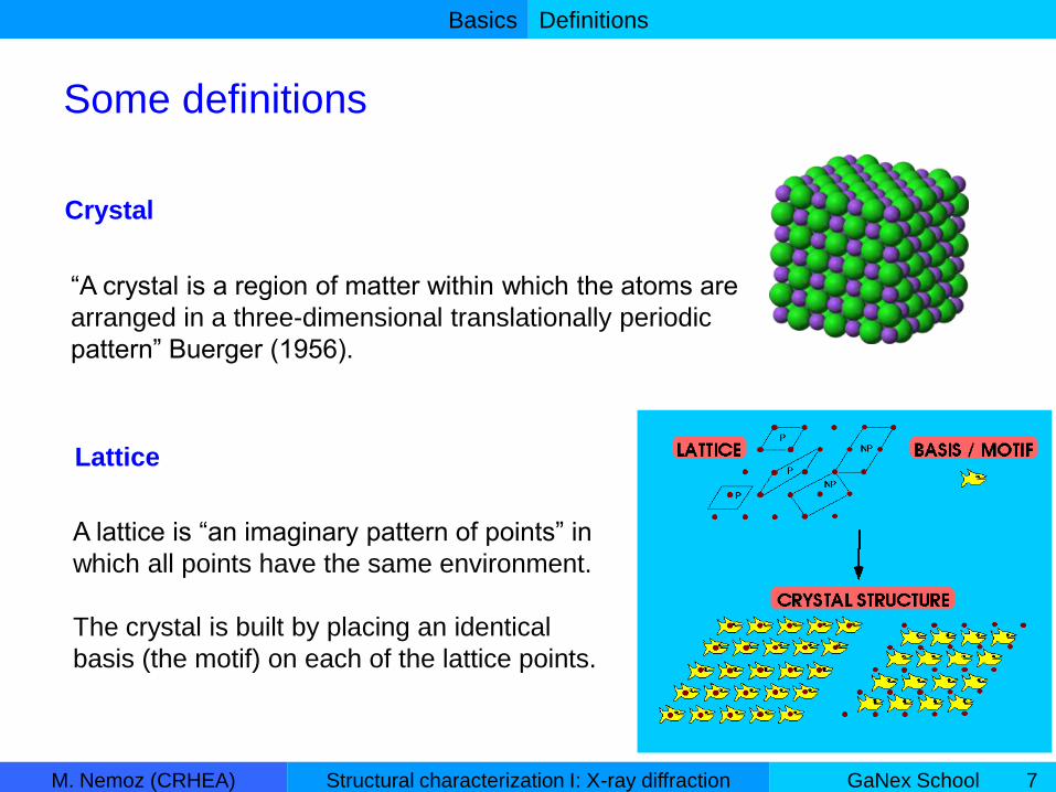
“A crystal is a region of matter within which the atoms are
arranged in a three-dimensional translationally periodic
pattern” Buerger (1956).
Lattice
A lattice is “an imaginary pattern of points” in
which all points have the same environment.
The crystal is built by placing an identical
basis (the motif) on each of the lattice points.
Definitions
Some definitions
Crystal

Basics
M. Nemoz (CRHEA) GaNex SchoolStructural characterization I: X-ray diffraction 8
The building block of the crystal structure.
Corners are lattice points.
Primitive (contains 1 point)
or non-primitive.
Unit Cell
Definitions
Lattice parameters
Lengths: a, b, c
Angles: α, β, γ

Basics
M. Nemoz (CRHEA) GaNex SchoolStructural characterization I: X-ray diffraction 9
A crystal structure is “created” by replicating a motif with a variety of operations:
■ translations
■ rotation axes (symbols: 1,2,3,4,6 = nb of times the form is repeated in a 360º
rotation)
■ mirror planes (symbol: m)
■ center of symmetry (symbol: )
■ inversion axes (combination of rotation and centre of symmetry operations)
Symmetry Operations
1
Basics
M. Nemoz (CRHEA) GaNex SchoolStructural characterization I: X-ray diffraction 10
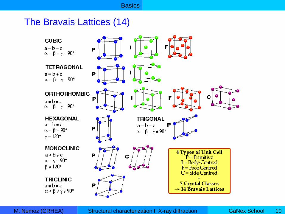
The Bravais Lattices (14)
Basics
M. Nemoz (CRHEA) GaNex SchoolStructural characterization I: X-ray diffraction 11
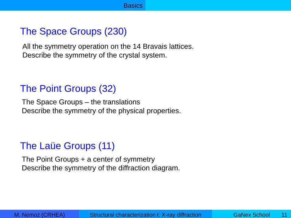
The Space Groups (230)
All the symmetry operation on the 14 Bravais lattices.
Describe the symmetry of the crystal system.
The Point Groups (32)
The Space Groups – the translations
Describe the symmetry of the physical properties.
The Laüe Groups (11)
The Point Groups + a center of symmetry
Describe the symmetry of the diffraction diagram.

Basics
M. Nemoz (CRHEA) GaNex SchoolStructural characterization I: X-ray diffraction 12
To draw a crystal structure, you need:
- the crystal system
(define the arrangement of the lattice points)
- the lattice parameters
(define the size and shape of the unit cell)
- the motif (groups of atoms)
(the repeated unit at each lattice points)
Crystal structure
Hexagonal
a = 3.189 Ǻ
c = 5.185 Ǻ
Example for GaN:
Ga1 (0, 0, 0)
N1 (0, 0, 3/8)
Ga2 (1/3, 2/3, 1/2)
N2 (1/3, 2/3, 1/2+3/8 )
Space Group: P63mc
Wurtzite structure

Basics
M. Nemoz (CRHEA) GaNex SchoolStructural characterization I: X-ray diffraction 13
A method of describing the orientation
of a plane in relation to the unit cell.
Lattice planes
The plane (hkl) intercepts :
• x-axis at a/h
• y-axis at b/k
• z-axis at c/l
h, k, and l are integers.
Miller indices

Basics
M. Nemoz (CRHEA) GaNex SchoolStructural characterization I: X-ray diffraction 14
A vector joining two lattice points.
A linear combination of the unit cell vectors (U, V and W are integers) :
Lattice vectors
cWbVaUR
UVWR

Basics
M. Nemoz (CRHEA) GaNex SchoolStructural characterization I: X-ray diffraction 15
• (hkl) a specific plane
• {hkl} a set of planes symmetrically equivalent
• [uvw] a specific vector or direction
• <uvw> a set of directions symmetrically equivalent
Crystallography conventions
How to write the indices of planes and directions?
Basics
M. Nemoz (CRHEA) GaNex SchoolStructural characterization I: X-ray diffraction 16
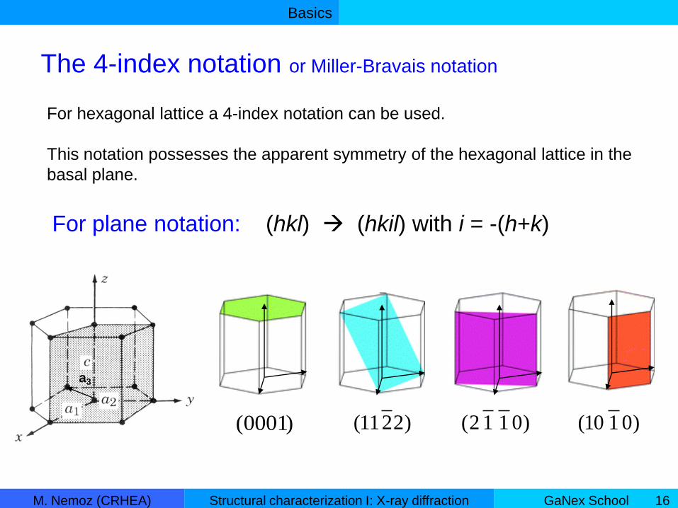
The 4-index notation or Miller-Bravais notation
For hexagonal lattice a 4-index notation can be used.
This notation possesses the apparent symmetry of the hexagonal lattice in the
basal plane.
a3
)0001( )0110()0112()2211(
For plane notation: (hkl) (hkil) with i = -(h+k)

Basics
M. Nemoz (CRHEA) GaNex SchoolStructural characterization I: X-ray diffraction 17
Circular permutation on hki:
(h k i l)
(i h k l)
(k i h l)
)0110(
a1
a2
a3
)1010(
a3
a1
a2
a2
a3
a1
)1001(

Basics
M. Nemoz (CRHEA) GaNex SchoolStructural characterization I: X-ray diffraction 18
Direction notations
UVWR
Directions in 4-index notation are less transparent in their construction.
uvtwR
Ww
VUvut
UVv
VUu
3
32
32
wW
tvV
tuU

Basics
M. Nemoz (CRHEA) GaNex SchoolStructural characterization I: X-ray diffraction 19
[1000] is not possible
because t ≠ -(u+v)
3-indices notation:
a1=[100]
4-indices notation ?
0
31
31310*2
32301*2
w
vut
v
u
u,v,t, w integers!
3a1=[2-1-10]
Basics
M. Nemoz (CRHEA) GaNex SchoolStructural characterization I: X-ray diffraction 20
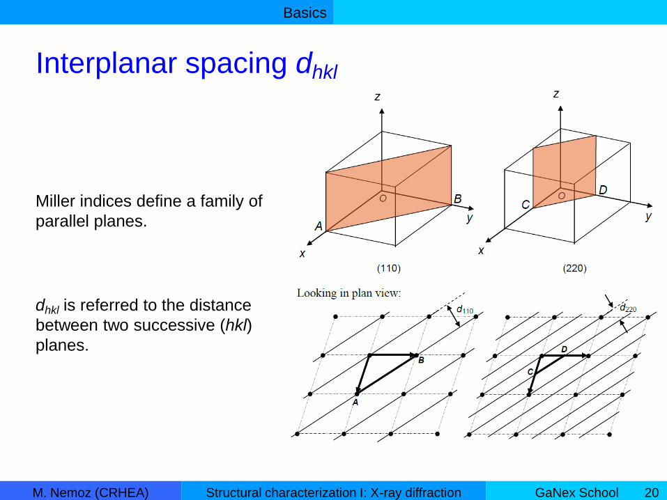
Interplanar spacing dhkl
Miller indices define a family of
parallel planes.
dhkl is referred to the distance
between two successive (hkl)
planes.

Basics
M. Nemoz (CRHEA) GaNex SchoolStructural characterization I: X-ray diffraction 21
2. Diffraction or the reciprocal space
I. Basics

Basics
M. Nemoz (CRHEA) GaNex SchoolStructural characterization I: X-ray diffraction 22
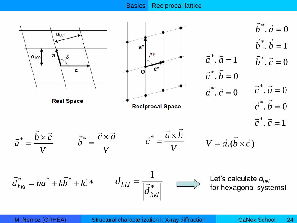
Reciprocal lattice vector
Reciprocal lattice

Basics
M. Nemoz (CRHEA) GaNex SchoolStructural characterization I: X-ray diffraction 23
A reciprocal lattice vector can be defined from the reciprocal unit vectors :
h, k, l are the Miller indices of the plane (hkl).
****
clbkahdhkl
Reciprocal lattice
*
1
hkl
hkld
d
The vector of the reciprocal lattice is normal
to the (hkl) plane of the crystal lattice.
*hkld
The reciprocal lattice points are indexed hkl with no brackets
The reciprocal lattice
Basics
M. Nemoz (CRHEA) GaNex SchoolStructural characterization I: X-ray diffraction 24
Reciprocal lattice
0.
0.
1.
*
*
*
ca
ba
aa
0.
1.
0.
*
*
*
cb
bb
ab
1.
0.
0.
*
*
*
cc
bc
ac
V
cba
*
V
acb
*
V
bac
*
).( cbaV
*
1
hkl
hkld
d Let’s calculate dhkl
for hexagonal systems! *
***clbkahdhkl

Basics
M. Nemoz (CRHEA) GaNex SchoolStructural characterization I: X-ray diffraction 25
Reciprocal lattice

Basics
M. Nemoz (CRHEA) GaNex SchoolStructural characterization I: X-ray diffraction 26
sin2dn
Constructive interference:
the path difference δ should be an integral number n of wavelengths λ.
δ=AB+BC = 2dsinθ
d
The Bragg’s law
θ
A
B
C
θ
Basics
M. Nemoz (CRHEA) GaNex SchoolStructural characterization I: X-ray diffraction 27
X-ray scattering
• X-rays are electromagnetic radiations (~1Ǻ).
• Photons energy : (~10keV).
• Interacts with atoms in many different ways :
Compton, Auger, fluorescence and elastic scattering.
• Elastic scattering (or coherent scatter) structural information.
/hchE

Basics
M. Nemoz (CRHEA) GaNex SchoolStructural characterization I: X-ray diffraction 28
Elastic scattering
The electric field vector of x-rays vibrate the atomic charges.
X-ray electric field vector :
• Scattered wave from an electron :
where is the electron radius
tjeEE
0
)(0),(rktj
ee er
ErtrE
er
ieat ftrEtrE ).,(),(
dvemfmkkj
atome
i
)( 0).(
)(m
The atomic scattering
factor increase with
the atomic number :
I (InN) > I (GaN)
fi is calculated for all atoms in the “International Tables for Crystallography” Vol C.
• Scattered wave from an atom :
where
the atomic scattering factor
: the electronic density
Basics
M. Nemoz (CRHEA) GaNex SchoolStructural characterization I: X-ray diffraction 29
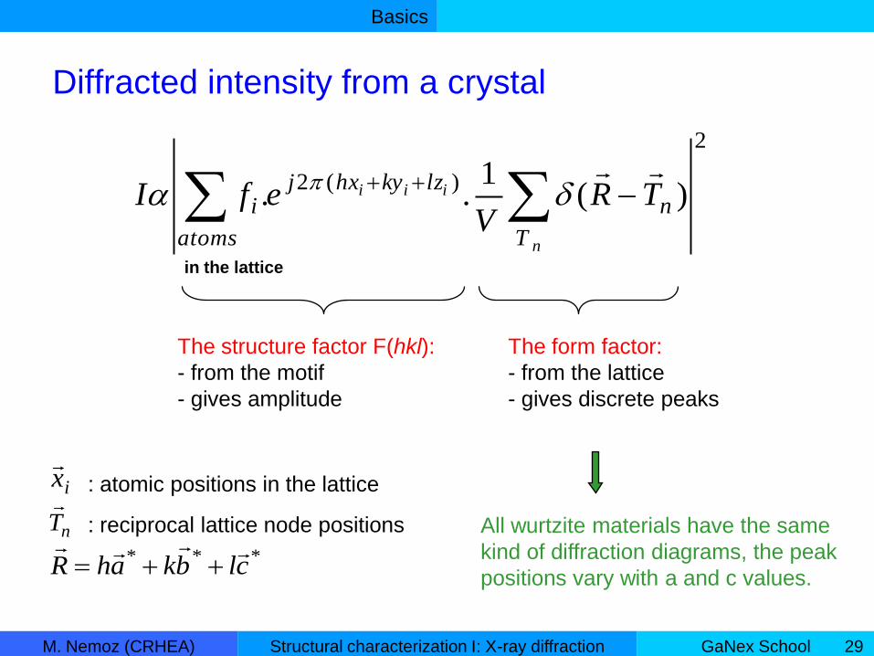
2
)(2)(
1.. n
T
lzkyhxj
atoms
i TRV
efI
n
iii
The structure factor F(hkl):
- from the motif
- gives amplitude
The form factor:
- from the lattice
- gives discrete peaks
ix
nT
: atomic positions in the lattice
in the lattice
: reciprocal lattice node positions
***clbkahR
All wurtzite materials have the same
kind of diffraction diagrams, the peak
positions vary with a and c values.
Diffracted intensity from a crystal
Basics
M. Nemoz (CRHEA) GaNex SchoolStructural characterization I: X-ray diffraction 30
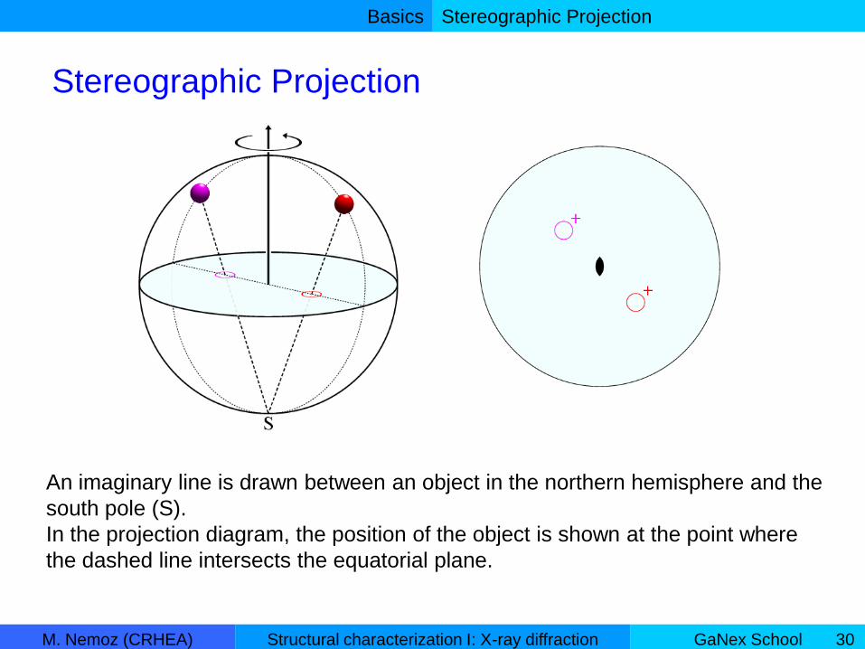
Stereographic Projection
Stereographic Projection
An imaginary line is drawn between an object in the northern hemisphere and the
south pole (S).
In the projection diagram, the position of the object is shown at the point where
the dashed line intersects the equatorial plane.
Basics
M. Nemoz (CRHEA) GaNex SchoolStructural characterization I: X-ray diffraction 31
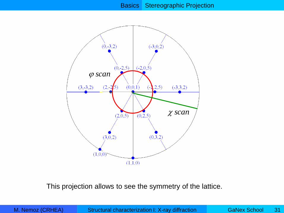
Stereographic Projection
This projection allows to see the symmetry of the lattice.
scan
scan

Basics
M. Nemoz (CRHEA) GaNex SchoolStructural characterization I: X-ray diffraction 32
Stereographic Projection
001 valuesall

The diffractometer
M. Nemoz (CRHEA) GaNex SchoolStructural characterization I: X-ray diffraction 33
II. The 4-circles diffractometer
1. General overview
2. X-ray source
3. Primary optics
4. Sample stage
5. Secondary optics
The diffractometer
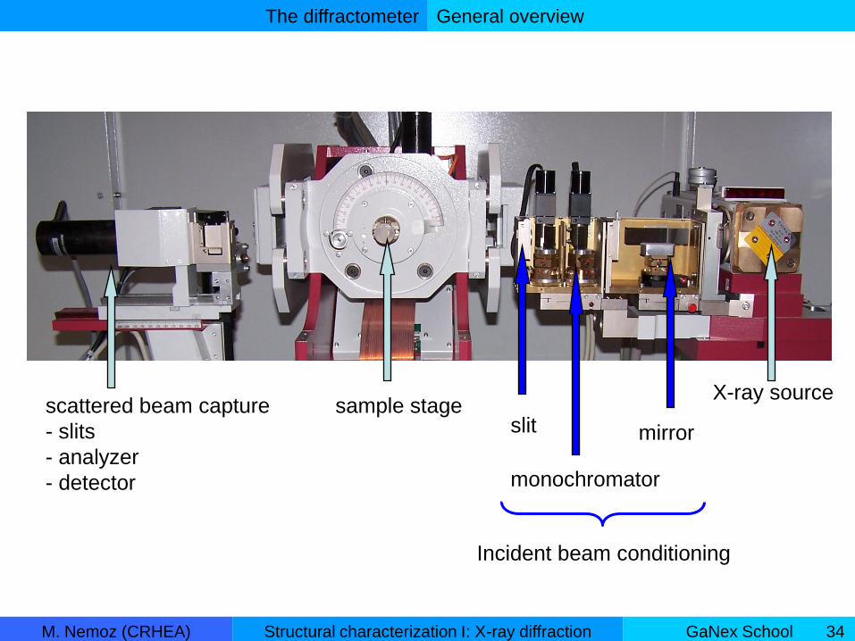
M. Nemoz (CRHEA) GaNex SchoolStructural characterization I: X-ray diffraction 34
X-ray sourcesample stagescattered beam capture
- slits
- analyzer
- detector
General overview
Incident beam conditioning
mirror
monochromator
slit

The diffractometer
M. Nemoz (CRHEA) GaNex SchoolStructural characterization I: X-ray diffraction 35
General overview
The angles associated with the diffractometer movements:
• 3 sample’s rotations: ω, φ, χ
• 1 detector’s rotation: 2θ
sample
φ
χω
2θ
Incident beamDiffracted beam
ω

The diffractometer
M. Nemoz (CRHEA) GaNex SchoolStructural characterization I: X-ray diffraction 36
Anode (target): Cu, Mo, Fe, Co, Cr.
Into an evacuated tube:
- electrons are emitted from a heated tungsten filament
- then accelerated by an electric potential (~40kV)
- to impinge on a metal target
X-ray source
X-ray laboratory source

The diffractometer
M. Nemoz (CRHEA) GaNex SchoolStructural characterization I: X-ray diffraction 37
characteristic
radiation
The anode is irradiated with a beam of high-energy electrons.
These electrons:
– loose energy when they arrived in the anode: this energy is transform into radiation.
a broad band of continuous radiation (bremsstrahlung or white radiation)
– remove inner electron: allow electrons of high energy states to transfer to the vacant inner states.
the emission lines with well defined energies corresponding to electron transition of the atom: Kα1, Kα2, Kβ.
Anode K1 (Ǻ)
Cu 1.54060
Cr 2.28970
Fe 1.93604
Co 1.78897
Mo 0.70930
continuous
radiation
X-ray source
The diffractometer
M. Nemoz (CRHEA) GaNex SchoolStructural characterization I: X-ray diffraction 38
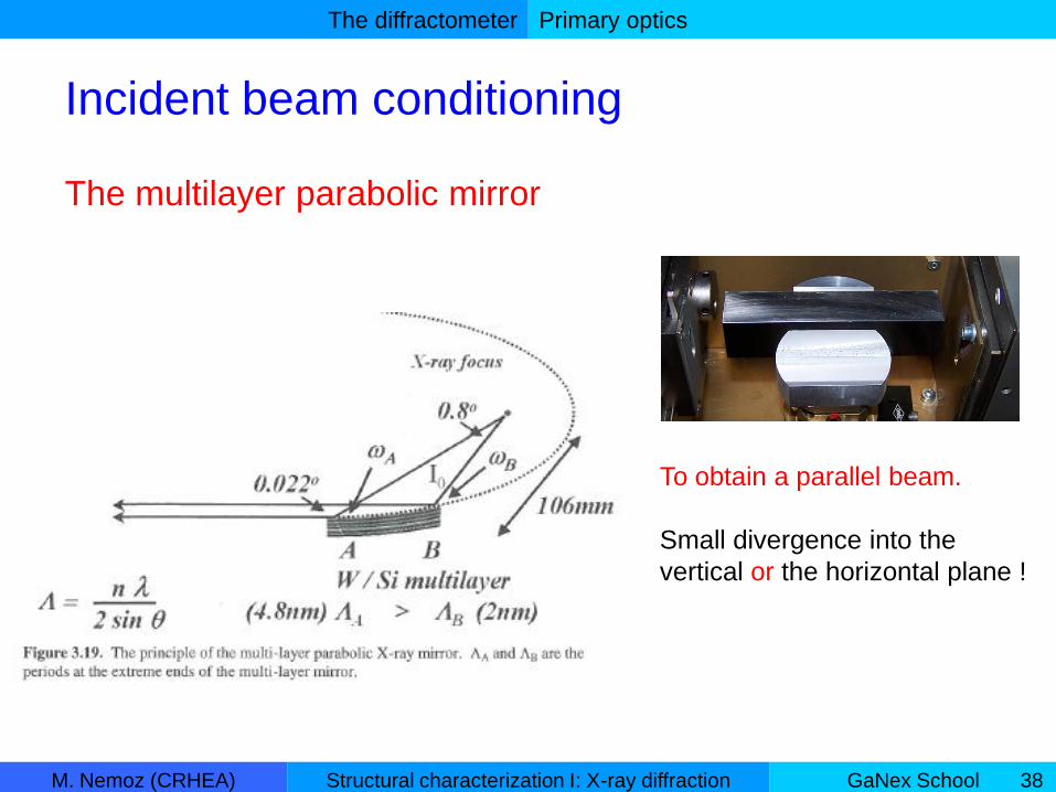
Primary optics
Incident beam conditioning
The multilayer parabolic mirror
To obtain a parallel beam.
Small divergence into the
vertical or the horizontal plane !

The diffractometer
M. Nemoz (CRHEA) GaNex SchoolStructural characterization I: X-ray diffraction 39
Primary optics
The monochromator
A single crystal of known orientation and d-spacing.
Following the Bragg law, each component wavelength of a polychromatic beam
will be diffracted at a discrete angle.
Only the radiation of interest (Kα1) can go out the diffractometer ± Δλ.
Δλ instrumental peak broadening.
High intensity cost.
To obtain a monochromatic beam.

The diffractometer
M. Nemoz (CRHEA) GaNex SchoolStructural characterization I: X-ray diffraction 40
Sample stage
3 translations:
• X,Y mapping
• Z to put the surface of the sample at the center of the diffractometer (ie
the center of all the rotations ω, θ, φ, χ).
2 rotations:
sample orientation: to put the normal of the atomic planes parallel to the
φ-axis.
Before sample orientation After sample orientation
φ
ωθ
ω ≠ θ
θ
φ
ωθ
ω ≈ θ
θ

The diffractometer
M. Nemoz (CRHEA) GaNex SchoolStructural characterization I: X-ray diffraction 41
Secondary optics
• none (open detector)
• slits
• analyzer (or secondary-beam monochromator)
Detector
• single point
• line (1D) detector
• area (2D) detector (need 2D beam conditioning)
The diffractometer
M. Nemoz (CRHEA) GaNex SchoolStructural characterization I: X-ray diffraction 42
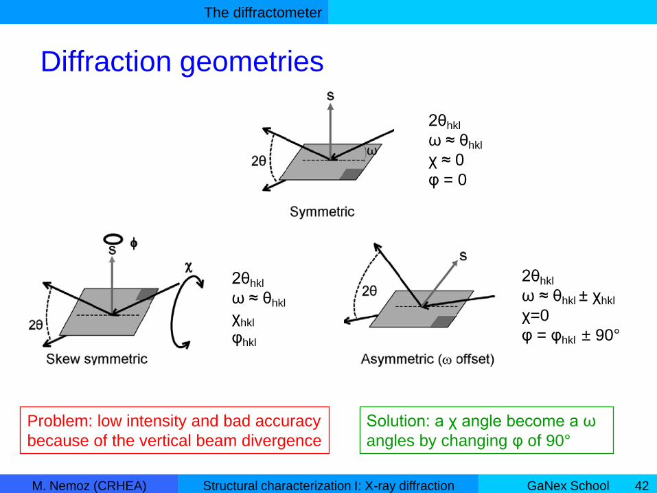
Diffraction geometries
2θhkl
ω ≈ θhkl
χ ≈ 0
φ = 0
2θhkl
ω ≈ θhkl
χhkl
φhkl
2θhkl
ω ≈ θhkl ± χhkl
χ=0
φ = φhkl ± 90°
Problem: low intensity and bad accuracy
because of the vertical beam divergence
Solution: a χ angle become a ω
angles by changing φ of 90°

Diffraction from materials
M. Nemoz (CRHEA) GaNex SchoolStructural characterization I: X-ray diffraction 43
1. Powder
2. Thin films
• Phase identification
• Layer thickness
• Layer orientation
• Lattice parameters
• Alloy composition
• Defects
3. Multilayers
III. Diffraction from materials

Diffraction from materials
M. Nemoz (CRHEA) GaNex SchoolStructural characterization I: X-ray diffraction 44
Order in thin films
Polycrystalline: many crystallites of varying orientation
Textured: the growth orientation is defined
but several in plane orientation
Epitaxial: perfect registry with the orientation of the
under layer
Amorphous: no order

Diffraction from materials
M. Nemoz (CRHEA) GaNex SchoolStructural characterization I: X-ray diffraction 45
Powder diffraction
A powder is a polycrystalline material in which there
are all possible orientations of the crystals.
The 2θ/ω scan of a powder show the positions of all possible reflections.
The GaN powder diagram simulated with the CaRine software 2θ values

Diffraction from materials
M. Nemoz (CRHEA) GaNex SchoolStructural characterization I: X-ray diffraction 46
Thin films : phase and orientation
Symmetric 2θ/ω scan
Data
GaN
powder diagram
sapphire 300
Epitaxial films: only the growth planes are in diffraction condition

Diffraction from materials
M. Nemoz (CRHEA) GaNex SchoolStructural characterization I: X-ray diffraction 47
Layer thickness
Symmetric 2θ/ω scan for a hkl reflection
GaN layer
1 µm
200 nm
50 nm
cos)2(t
)2(
main peak
thickness fringes
Scherrer equation
GaN 002 2θ/ω diagram simulated with the X’Pert Epitaxy software.

Diffraction from materials
M. Nemoz (CRHEA) GaNex SchoolStructural characterization I: X-ray diffraction 48
Layer orientation
substrate
layer
tilt
ω-scans for a symmetric reflection with φ loop.
0 60 120 180 240 300 360
-2
-1
0
1
2
Tilt
Ga
N/S
i (°
)
phi(°)
0 60 120 180 240 300 36010
12
14
16
18
20
(
°)phi (°)
w GaN 002
w Si 111
substrate
miscut
If at phi=180° the flat is perpendicular to the ω axis the tilt GaN / Si is parallel to the flat.
ssllsltilt /
ω
ω
Diffraction from materials
M. Nemoz (CRHEA) GaNex SchoolStructural characterization I: X-ray diffraction 49
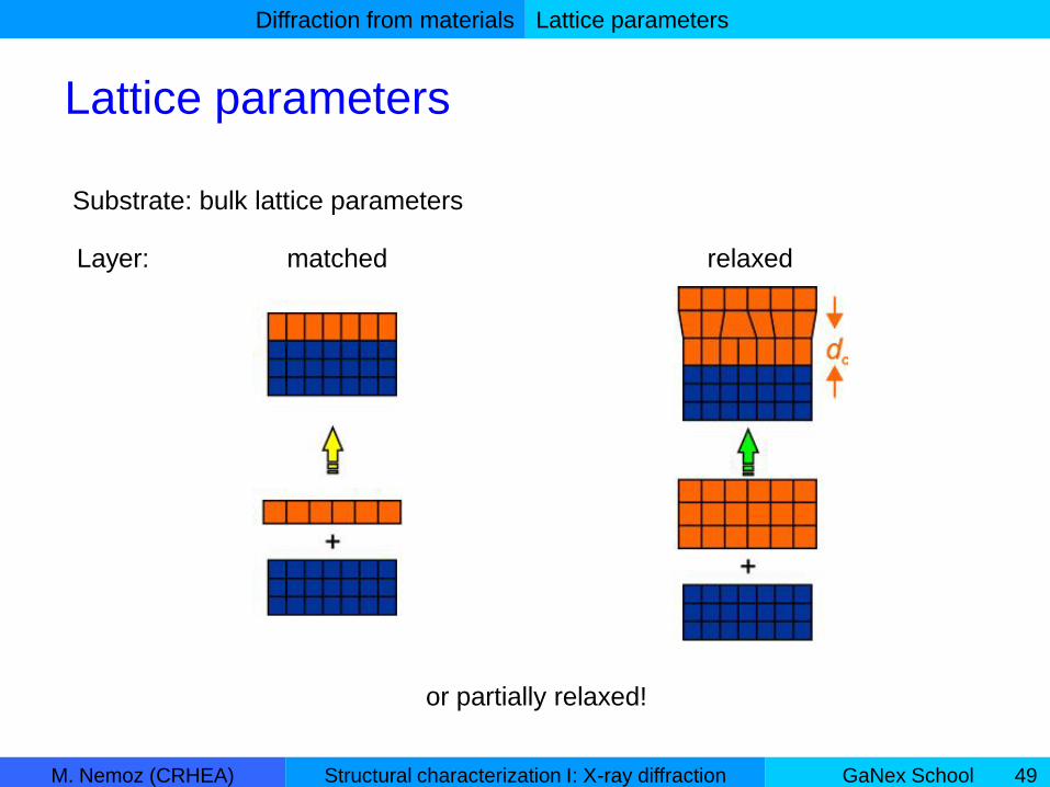
Lattice parameters
Substrate: bulk lattice parameters
Layer: matched relaxed
or partially relaxed!
Lattice parameters

Diffraction from materials
M. Nemoz (CRHEA) GaNex SchoolStructural characterization I: X-ray diffraction 50
For hexagonal lattices:
2
222
23
4
1
c
lhkkh
a
dhkl
Bragg law: sin2 hkld
Where θ is the half part of the detector position (≠ω be careful)
l
cd l 00
At least 2 dhkl are needed, with good choice of hkl.
h
adh
2
300
Lattice parameters

Diffraction from materials
M. Nemoz (CRHEA) GaNex SchoolStructural characterization I: X-ray diffraction 51
• Symmetric reflections are 00l reflections:
symmetric 2θ/ω scans d00l c lattice parameter
• h00 reflections are in-plane reflections: too weak intensities we can’t
measure directly the a lattice parameter!
• With the c value and one dh0l we can determine the a value.
dh0l is determined from asymmetric 2θ/ω scans.
Example for c-plane GaN:
2
2
2
20
3
4
1
c
l
a
hd lh
Lattice parameters
Diffraction from materials
M. Nemoz (CRHEA) GaNex SchoolStructural characterization I: X-ray diffraction 52
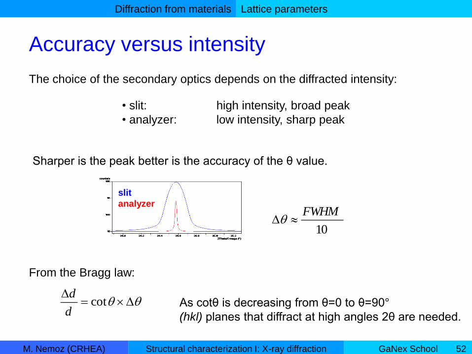
Accuracy versus intensity
• slit: high intensity, broad peak
• analyzer: low intensity, sharp peak
The choice of the secondary optics depends on the diffracted intensity:
slit
analyzer
Sharper is the peak better is the accuracy of the θ value.
cotd
d
From the Bragg law:
10
FWHM
As cotθ is decreasing from θ=0 to θ=90°
(hkl) planes that diffract at high angles 2θ are needed.
Lattice parameters

Diffraction from materials
M. Nemoz (CRHEA) GaNex SchoolStructural characterization I: X-ray diffraction 53
Lattice parameters from RSM
Reciprocal Space Map (RSM):
a series of 2θ/ω scans at successive ω values.
sin21
hkldS
sinsin2
xS
cossin2
zSS
xS
zS
Lattice parameters
An other method is to measure 2θ and ω.
2θ and ω are converted into reciprocal lattice
units s:
hklhkl

Diffraction from materials
M. Nemoz (CRHEA) GaNex SchoolStructural characterization I: X-ray diffraction 54
Lattice parameters from RSM
Lattice parameters
For c-plane films: 00
1
h
xd
S l
zd
S00
1

Diffraction from materials
M. Nemoz (CRHEA) GaNex SchoolStructural characterization I: X-ray diffraction 55
Alloy composition
For a biaxial strain in a hexagonal system the out-of-plane strain is related to the
in-plane strain by the C13 and C33 components of the elastic stiffness tensor :
0
0
33
13
0
0 2
a
aa
C
C
c
cc measmeas
Vegard’s rule:
The lattice parameters of an alloy vary linearly between the end members.
where cmeas and ameas are the measured strained parameters
c0 and a0 are the relaxed parameters
The elastic constants C13 and C33 are linearly interpolated between the values for
the end members. A graphical method can be used to find the composition.
Alloy composition

Diffraction from materials
M. Nemoz (CRHEA) GaNex SchoolStructural characterization I: X-ray diffraction 56
Thin films : defects
substrate
lateral
coherence
length
vertical
coherence
length
tilt angletwist angle
GaN layers can be described as mosaic crystals characterized by both the mean
size of the mosaic blocks and the mean angle of their rotation against each other.
The angles between the mosaic blocks are correlated with the densities of
threading dislocations (TD).
Defects

Diffraction from materials
M. Nemoz (CRHEA) GaNex SchoolStructural characterization I: X-ray diffraction 57
The slope = The tilt angle α
The interceptions with the ordinate The lateral correlation length L||
with open detector!
β is the FWHM of the ω-scan
(rocking curve)
Defects
The Williamson–Hall plots
For c-plane GaN layers:
• ω-scans of 00l reflections the tilt
• ω -scans of h0l reflections (skew geometry) the twist
Diffraction from materials
M. Nemoz (CRHEA) GaNex SchoolStructural characterization I: X-ray diffraction 58
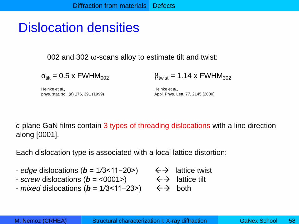
c-plane GaN films contain 3 types of threading dislocations with a line direction
along [0001].
Each dislocation type is associated with a local lattice distortion:
- edge dislocations (b = 1/3<11−20>) lattice twist
- screw dislocations (b = <0001>) lattice tilt
- mixed dislocations (b = 1/3<11−23>) both
Defects
Dislocation densities
Heinke et al.,
Appl. Phys. Lett. 77, 2145 (2000)
βtwist = 1.14 x FWHM302αtilt = 0.5 x FWHM002
Heinke et al.,
phys. stat. sol. (a) 176, 391 (1999)
002 and 302 ω-scans alloy to estimate tilt and twist:
Diffraction from materials
M. Nemoz (CRHEA) GaNex SchoolStructural characterization I: X-ray diffraction 59
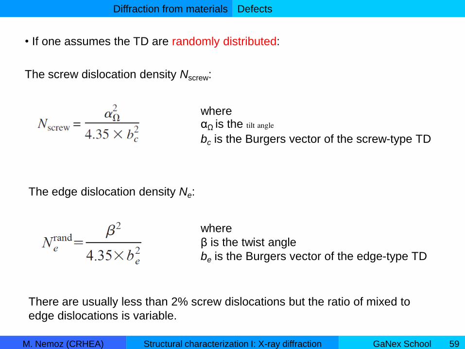
where αΩ is the tilt angle
bc is the Burgers vector of the screw-type TD
• If one assumes the TD are randomly distributed:
The screw dislocation density Nscrew:
There are usually less than 2% screw dislocations but the ratio of mixed to
edge dislocations is variable.
The edge dislocation density Ne:
where
β is the twist angle
be is the Burgers vector of the edge-type TD
Defects
Diffraction from materials
M. Nemoz (CRHEA) GaNex SchoolStructural characterization I: X-ray diffraction 60
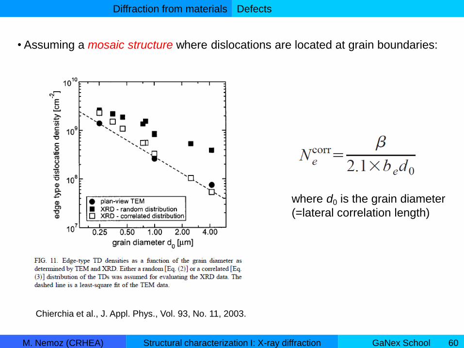
Chierchia et al., J. Appl. Phys., Vol. 93, No. 11, 2003.
where d0 is the grain diameter
(=lateral correlation length)
• Assuming a mosaic structure where dislocations are located at grain boundaries:
Defects

Diffraction from materials
M. Nemoz (CRHEA) GaNex SchoolStructural characterization I: X-ray diffraction 61
Structure factor
layer A
Structure factor
layer B
Structure factor
N layer of thickness Λ
Diffracted intensity
superlattice
hkl reflection
2
For each hkl reflection, a lot of “satellite” peaks:
- from the space between the satellites the superlattice period Λ
- from the position of the 0 order satellite the average composition of
the bi layer (A+B)
- from the relative intensity A and B composition and thickness
cos)2(
)2(
Multilayers
Multilayers

Diffraction from materials
M. Nemoz (CRHEA) GaNex SchoolStructural characterization I: X-ray diffraction 62
Period sensitivity
Average composition
sensitivity
4.2% 3.0%aveInC
18.9 nm 20.0 nmsapphire
GaN template
InGaN
GaNx10
Multilayers
0+1
+2
-1-2
-3
Bi-layer
parameters
Diffraction from materials
M. Nemoz (CRHEA) GaNex SchoolStructural characterization I: X-ray diffraction 63
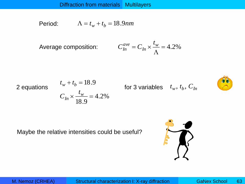
Period: nmtt bw 9.18
Average composition: %2.4
wIn
aveIn
tCC
2 equations9.18 bw tt
%2.49.18 w
In
tC
for 3 variables Inbw Ctt ,,
Maybe the relative intensities could be useful?
Multilayers

Diffraction from materials
M. Nemoz (CRHEA) GaNex SchoolStructural characterization I: X-ray diffraction 64
24%20% 30%InCbw tandt
are adjusted to fit
andCaveIn
The relative intensities
vary for the high order
satellite peaks.
A peak with a minimum
intensity is helpful!
Multilayers

Diffraction from materials
M. Nemoz (CRHEA) GaNex SchoolStructural characterization I: X-ray diffraction 65
Slit or analyzer ?
The thickness fringes is a merit figure of the superlattice.
The slit allows to measure the weak high order satellite peaks.
Both!
Multilayers

M. Nemoz (CRHEA) GaNex SchoolStructural characterization I: X-ray diffraction 66
The end
X-ray diffraction is a powerful tool to
characterize the structure of ordered
materials.

M. Nemoz (CRHEA) GaNex SchoolStructural characterization I: X-ray diffraction 67

M. Nemoz (CRHEA) GaNex SchoolStructural characterization I: X-ray diffraction 68

M. Nemoz (CRHEA) GaNex SchoolStructural characterization I: X-ray diffraction 69
βm is the measured FWHM
β0 is the intrinsic rocking curve width of the crystal
βd is the instrumental broadening width
βα lattice rotations at dislocations (tilt or twist)
βε lattice strain at dislocations (microstrain)
βL limited correlation lengths
βr wafer curvature
Defects
Other broadening factors
β0 and βd are usually small compared with the tilt and the twist (a few arcsec).
For relatively high dislocation density films, βα (tilt or twist) dominates and can be
used as a measure of dislocation densities.

M. Nemoz (CRHEA) GaNex SchoolStructural characterization I: X-ray diffraction 70

M. Nemoz (CRHEA) GaNex SchoolStructural characterization I: X-ray diffraction 71
Alloy composition in semi-polar films
New coordinate systems rotation of tensors
Hooke’s law a term of shear appears
Alloy composition
M. Nemoz (CRHEA) GaNex SchoolStructural characterization I: X-ray diffraction 72
• non-polar and semipolar films contain additional defects such as:
intrinsic (I1, I2 and I3) and extrinsic (E) basal plane stacking faults (BSFs).
• I1 BSFs formed by the insertion of an atomic plane (1/2 [0001]), followed by a
shift of 1/3<1−100>, are bounded by sessile partial dislocations and arise due to
growth errors. Typically, around 90% of observed BSFs are I1-type, as these have
the lowest formation energy.
• The 10−10 and 20−20 reflections will be broadened by I1 and I2 BSFs when
analysed in the skew symmetric geometry, whereas the 30−30 reflections will not
be affected.
Defects in non-polar and semipolar films
Defects


