SANDIA REPORT SAND2011-9066 Unlimited Release Printed December 2011 Structural Considerations for Solar Installers An Approach for Small, Simplified Solar Installations in Madison, WI Stephen Dwyer, PhD, PE, Alan Harper, William Lindau, PE, Tom Bosiljevac, PE, Kay Schindel, Elizabeth Richards, PhD Prepared by Sandia National Laboratories Albuquerque, New Mexico 87185 and Livermore, California 94550 Sandia National Laboratories is a multi-program laboratory managed and operated by Sandia Corporation, a wholly owned subsidiary of Lockheed Martin Corporation, for the U.S. Department of Energy’s National Nuclear Security Administration under Contract DE-AC04-94AL85000.
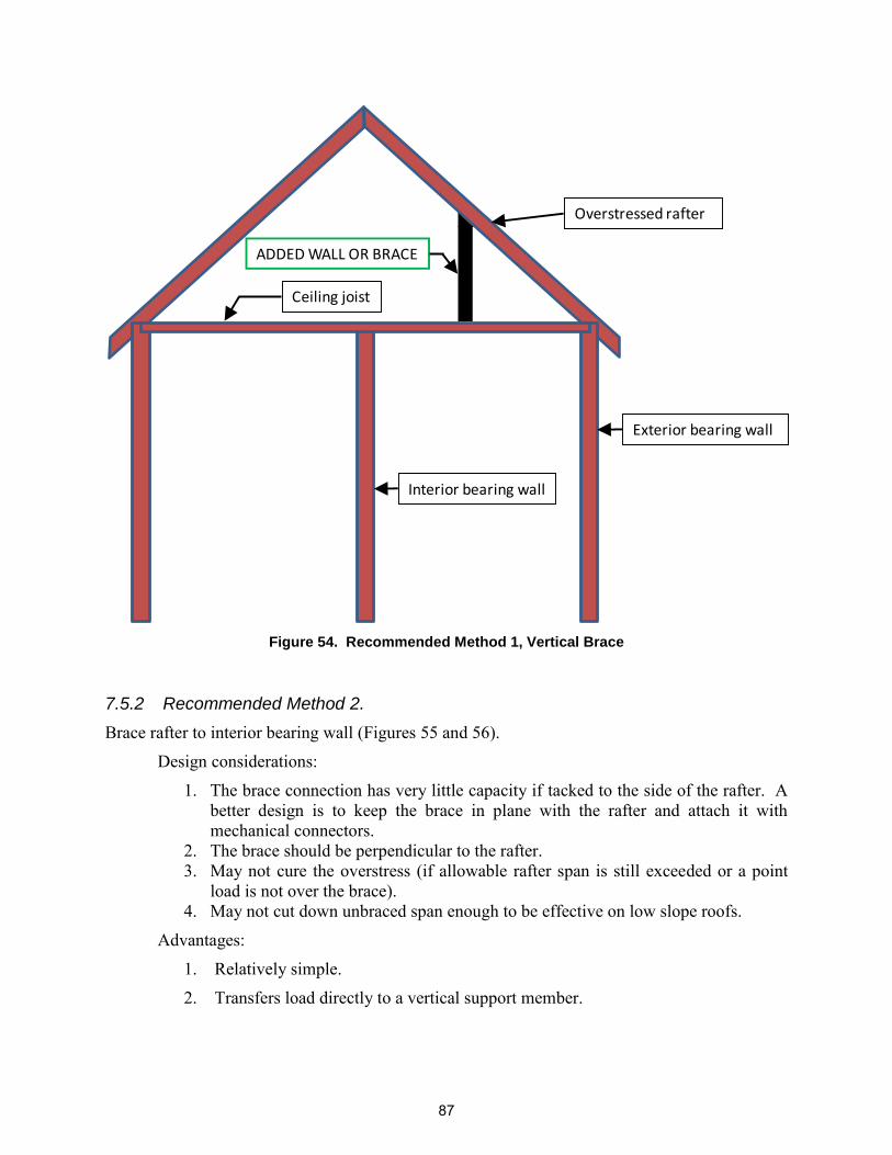
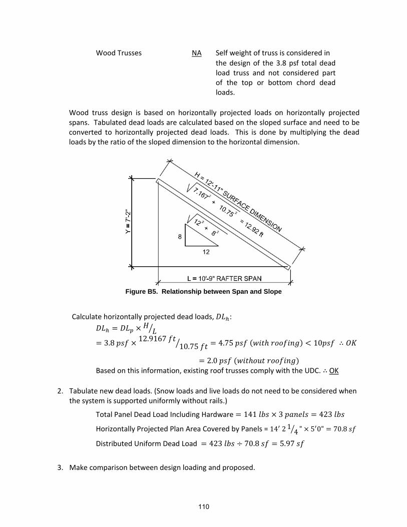
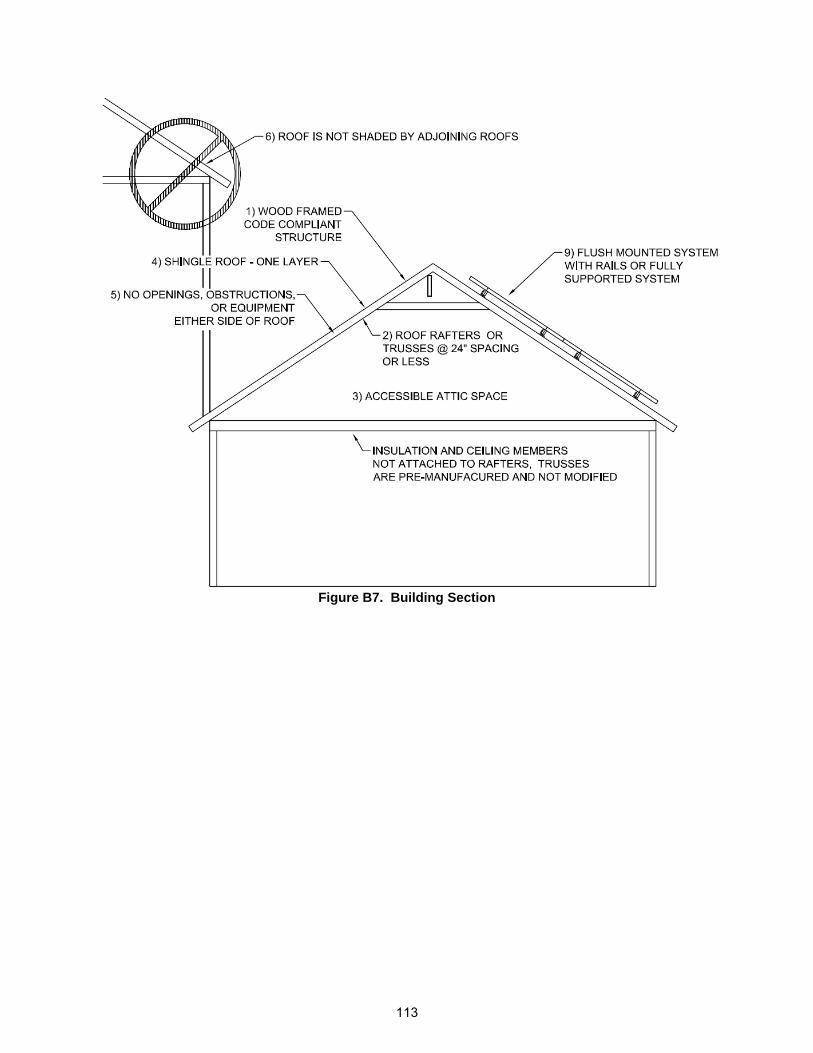
Transcript
SANDIA REPORT SAND2011-9066 Unlimited Release Printed December 2011
Structural Considerations for Solar Installers
An Approach for Small, Simplified Solar Installations in Madison, WI Stephen Dwyer, PhD, PE, Alan Harper, William Lindau, PE, Tom Bosiljevac, PE, Kay Schindel, Elizabeth Richards, PhD Prepared by Sandia National Laboratories Albuquerque, New Mexico 87185 and Livermore, California 94550 Sandia National Laboratories is a multi-program laboratory managed and operated by Sandia Corporation, a wholly owned subsidiary of Lockheed Martin Corporation, for the U.S. Department of Energy’s National Nuclear Security Administration under Contract DE-AC04-94AL85000.
Issued by Sandia National Laboratories, operated for the United States Department of Energy by Sandia Corporation.
NOTICE: This report was prepared as an account of work sponsored by an agency of the United States Government. Neither the United States Government, nor any agency thereof, nor any of their employees, nor any of their contractors, subcontractors, or their employees, make any warranty, express or implied, or assume any legal liability or responsibility for the accuracy, completeness, or usefulness of any information, apparatus, product, or process disclosed, or represent that its use would not infringe privately owned rights. Reference herein to any specific commercial product, process, or service by trade name, trademark, manufacturer, or otherwise, does not necessarily constitute or imply its endorsement, recommendation, or favoring by the United States Government, any agency thereof, or any of their contractors or subcontractors. The views and opinions expressed herein do not necessarily state or reflect those of the United States Government, any agency thereof, or any of their contractors.
2
SAND2011-9066 Unlimited Release
Printed December 2011
Structural Considerations for
Solar Installers
An approach for small, simplified solar installations or retrofits
Prepared by:
Stephen F. Dwyer, PhD, PE1 Alan Harper2
William Lindau, PE3 Tom Bosiljevac, PE4 Kay Schindel, ME5 Elizabeth Richards,
Sandia National Laboratories Albuquerque, New Mexico 87185
Abstract
Structural Considerations for Solar Installers provides a comprehensive outline of structural considerations associated with simplified solar installations and recommends a set of best practices installers can follow when assessing such considerations. Information in the manual comes from engineering and solar experts as well as case studies. The objectives of the manual are to ensure safety and structural durability for rooftop solar installations and to potentially accelerate the permitting process by identifying and remedying structural issues prior to installation.
1 Principal Member of Technical Staff, Sandia National Laboratories, Albuquerque, New Mexico 2 Plan Review Specialist III, City of Madison, Wisconsin, Building Inspection 3 Principal Engineer, Lindau Companies, Inc., Hudson, Wisconsin 4 Senior Member of Technical Staff, Sandia National Laboratories, Albuquerque, New Mexico 5 Engineer, City of Madison, Wisconsin – Facilities and Sustainability Management
3
ACKNOWLEDGMENTS
This report was made possible through funding from the U.S. Department of Energy‘s (DOE‘s) Solar America Communities program. To learn more, please visit www.solaramericacommunities.energy.gov. We also wish to acknowledge the leadership offered by Hannah Muller of DOE‘s Solar Energy Technologies Program. We would like to thank personnel from Solar America City Madison, Wisconsin, for their encouragement of this document. In addition, we would like to thank the multitude of reviewers that took the time to edit and contribute to this document.
Appendix A: Solar Installation Submittal Form ....................................................... 93
Appendix B: Design Examples (SAC Structural Considerations for Solar Installers in Wisconsin) ............................................................................................ 103
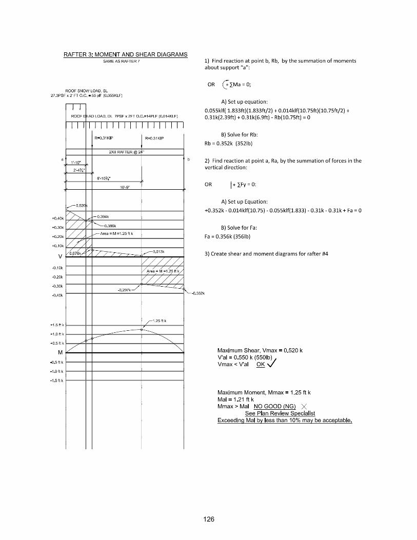
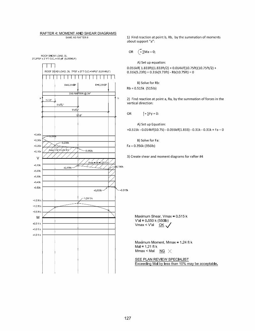
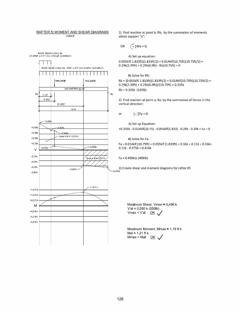
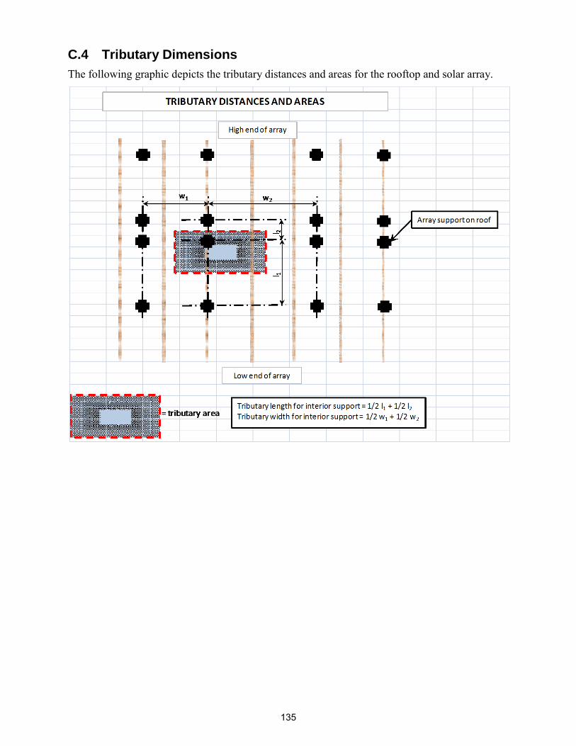
Appendix C: Solar Installation Submittal Form (SAC Structural Considerations for Solar Installers in Wisconsin)............................................................................. 128
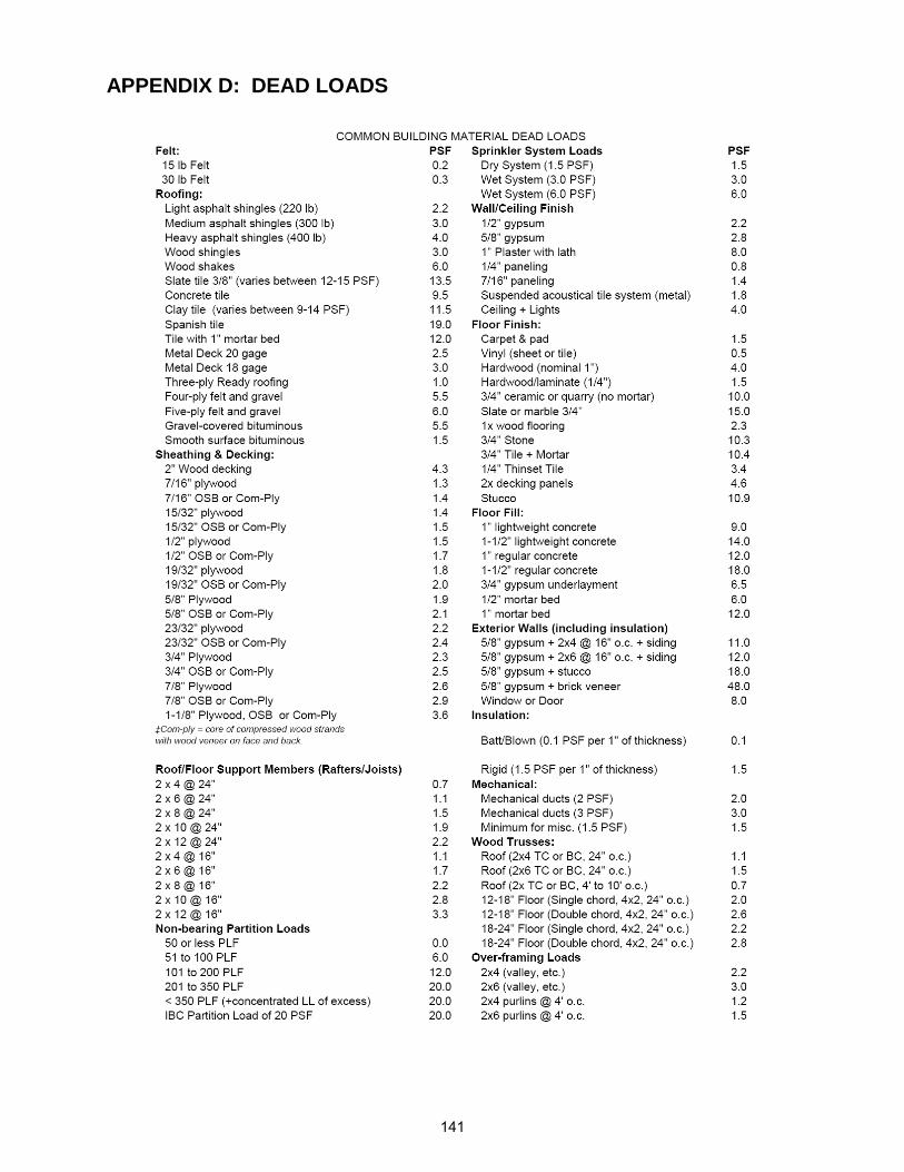
Appendix D: Dead Loads ......................................................................................... 139
6
FIGURES
Figure 1. Roof Collapse Due to Excessive Snow Load ............................................................... 11 Figure 2. Truss Failure Due to Excessive Roof Load .................................................................. 11 Figure 3. Bending in a Beam ....................................................................................................... 12 Figure 4. Vertical Shear in Beam ................................................................................................. 12 Figure 5. Horizontal Shear in Beam ............................................................................................ 13 Figure 6. Axial Load in Column .................................................................................................. 13 Figure 7. Site-built Truss (Denise 2007)...................................................................................... 20 Figure 8. Truss Connector Plate Misaligned (Denise 2007) ........................................................ 21 Figure 9. Knotholes Weaken Truss Web Members (Denise 2007) ............................................. 21 Figure 10. Truss Metal Connector Plates Partially Pulled out of Alignment (Denise 2007)....... 22 Figure 11. Compression Buckling of Truss Connector Plate Bent during Installation (Denise 2007) ............................................................................................................................................. 23 Figure 12. Truss Stamped "Permanent Lateral Bracing Required" (Denise 2007) ..................... 24 Figure 13. Bracing Not Provided Despite Being Stamped "Bracing Required" (Denise 2007) .. 24 Figure 14. Typical Bracing Configurations (Denise 2007) ......................................................... 26 Figure 15. CLR Not Effective when Applied to Trusses Without Similar Web Patterns (Denise 2007) ............................................................................................................................................. 26 Figure 16. Bracing Should be Centered (Denise 2007) ............................................................... 27 Figure 17. All Nail Holes Should be Filled-in Metal Hanger Brackets for Full Strength ........... 28 Figure 18. Unsupported Piggyback Trusses at Bearing Point (Denise 2007).............................. 29 Figure 19. Truss/Joists Should Not be Altered without Structural Engineering/Manufacturer Approval (Denise 2007) ................................................................................................................ 30 Figure 20. Typical Engineered Truss Repair ............................................................................... 31 Figure 21. Typical Tensile Test Results for Steel ........................................................................ 34
Figure 22. Typical Stress-Strain Curve for Steel ......................................................................... 34 Figure 23. Typical Stress-Strain Curve for Aluminum ................................................................ 35 Figure 24. Force Components ...................................................................................................... 36 Figure 25. Moment Components ................................................................................................. 37 Figure 26. Rectangular Cross-section .......................................................................................... 38 Figure 27. Typical Lumber Grade Stamp as Approved by ALSC and its Interpretation for Douglas Fir Lumber ...................................................................................................................... 48
Figure 29. Example of Alignment‘s Effect on Ability to Resist Bending ................................... 50 Figure 30. Simply Supported Beam with Applied Uniform Load (w) ........................................ 51
Figure 31. Minimum Acceptable Beam Size or Section Example .............................................. 53 Figure 32. Common Pitched Wood Roof Trusses ....................................................................... 54
Figure 33. Common Flat Wood Trusses ...................................................................................... 55 Figure 34. Truss Terminology ..................................................................................................... 55 Figure 35. Left Bar in Tension/Right Bar in Compression .......................................................... 57 Figure 36. Method of joints example ........................................................................................... 59 Figure 37. Method of sections example ....................................................................................... 60
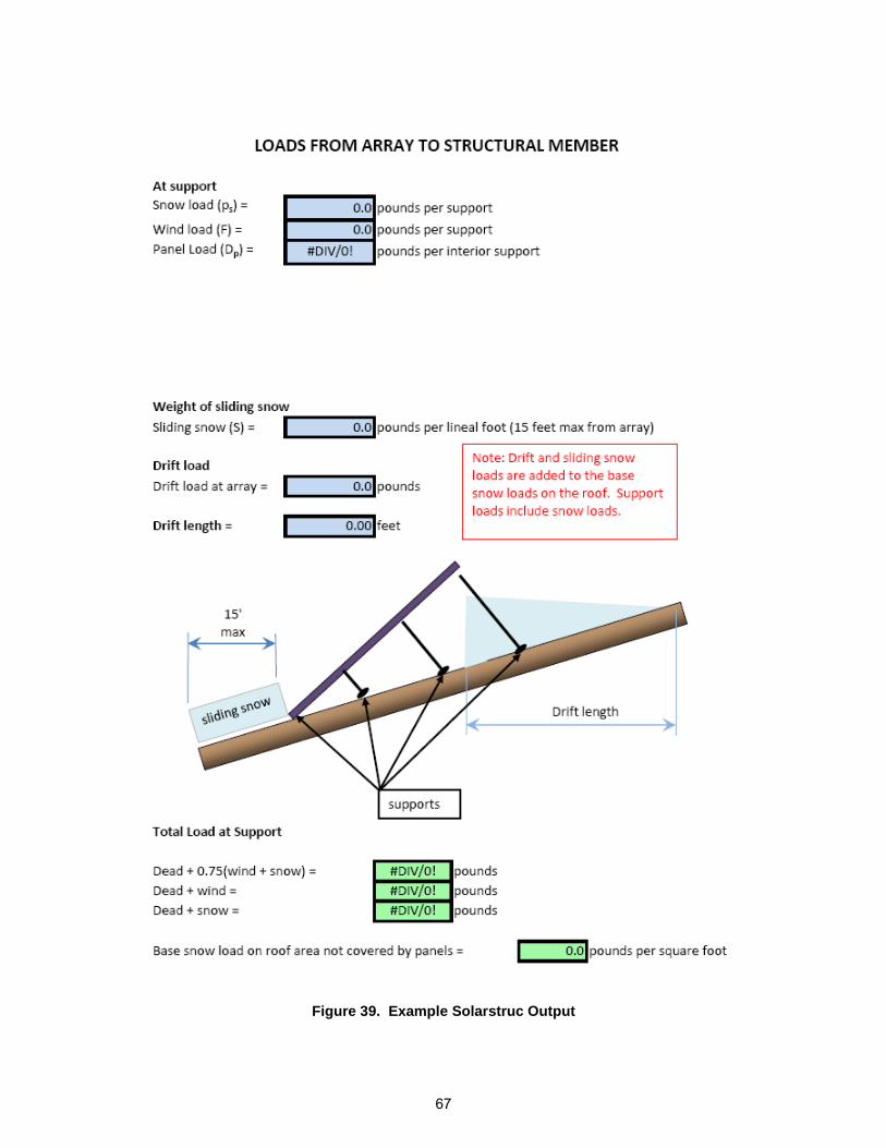
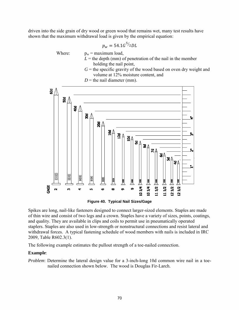
Figure 38. Combined loading example ........................................................................................ 61 Figure 39. Example Solarstruc Output......................................................................................... 65 Figure 40. Typical Nail Sizes/Gage ............................................................................................. 68
NOMENCLATURE AF&PA American Forest & Paper Association AISC American Institute of Steel Construction AISI American Iron and Steel Institute AITC American Institute of Timber Construction ANSI American National Standards Institute ASCE American Society of Civil Engineers ASHI American Society of Home Inspectors ASTM American Society for Testing and Materials AWC American Wood Council BCSI Building Component Safety Information CLR Continuous Lateral Restraint DOE Department of Defense IBC International Building Code ICC International Code Council IFI Industrial Fasteners Institute IRC International Residential Code KLF Kips per Linear Foot NDS National Design Specification NEC National Electric Code NRCA National Roofing Construction Association PLF Pound per Linear Foot PSF Pounds per Square Foot PV photovoltaic SAC Solar America Communities SETP Solar Energy Technologies Program SPF Spruce-Pine-Fir SRS Solar Racking System TPI Truss Plate Institute UDC Uniform Dwelling Code URL Uniform Resource Locator WTCA Wood Truss Council of America DOE Department of Defense SETP Solar Energy Technologies Program
9
10
INTRODUCTION 1
The mission of the U.S. Department of Energy‘s (DOE‘s) Solar Energy Technologies Program (SETP) is to conduct aggressive research, development, and deployment of solar energy technologies and systems to significantly reduce the cost of solar electricity by 2015. The Program achieves its mission through various initiatives, including public-private partnerships. The Solar America Communities (SAC) program is one such initiative. DOE designated 13 Solar America Cities in 2007 and an additional 12 cities in 2008 to develop comprehensive approaches to urban solar energy use that can serve as a model for cities around the nation. As a result of widespread success in the 25 Solar America Cities, DOE expanded SETP in 2010 by launching a national outreach effort and renaming the program Solar America Communities.
The SAC program has engaged more than 180 organizations including municipal, county, and state agencies; solar companies; universities; utilities; and non-profit organizations. The SAC program is working in partnership with these communities to break down barriers to the use of solar technologies, with the goal of making solar energy cost competitive with conventional energy sources by 2015.
One identified market barrier to new solar installations involves structural considerations in adhering to local building codes and in the construction permitting process. These considerations are primarily related to loads generated on roof systems but in some cases may be related to pole-mounted systems. There are two primary issues:
1. The extra time and expense required when a Professional Engineer must be involved in otherwise routine installations; and
2. Ensuring that the structural integrity of buildings and roofs is not compromised as a result of a solar installation, as well as ensuring structural integrity of the solar energy system itself under various weather conditions.
The purpose of this document is to provide tools and guidelines for installers to help ensure that residential photovoltaic (PV) power systems are properly specified and installed with respect to the continuing structural integrity of the building.
1.1 Code Requirements
Codes and standards have been put in place to provide minimum requirements to safeguard the public safety, health, and general welfare through affordability, structural strength, means of egress stability, sanitation, light and ventilation, energy conservation, and safety to life and property from fire and other hazards attributed to the built environment. All solar installations shall, at a minimum, meet applicable building codes and standards.
Code compliance involves following a series of steps (detailed in Chapter 1) of both the International Residential Code (IRC) and International Building Code (IBC). These codes are part of the International Code Council (ICC). Briefly, these steps include submittal of appropriate construction documentation; obtaining a permit; passing applicable inspections during and/or post-construction; and obtaining a certificate of occupancy or certificate of completeness. The IRC is generally a prescriptive code that specifies in detail exactly what materials are to be used and how they are to be assembled. The IBC tends to be a performance code that describes a level of accepted performance to which the assembly or construction must conform without specifically outlining how materials are to be assembled. Performance codes
11
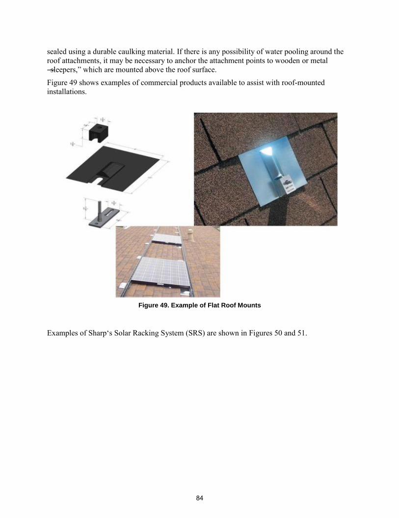
allow more flexibility and freedom in construction than do prescriptive codes. Further, the IBC tends to be a dynamic code that attempts to be adaptable to new construction materials.
Electrical code requirements for PV systems vary somewhat from one jurisdiction to the next, but most are based on the National Electrical Code (NEC). Article 690 in the NEC specifies requirements for designing and installing safe, reliable, code-compliant PV systems. The IBC and/or local codes and ordinances apply for mechanical and structural systems.
Building codes are dynamic and can vary by state, county, city, town, and/or borough. While some states—including Wisconsin, California, Florida, Massachusetts, Michigan, New York, and a few others—have their own set of building codes (typically based upon some version of the ICC with accommodations for local laws and regulations), most states have adopted the ICC series. The ICC codes are typically updated with a new printing every three years. At the time of this publication, the most recent ICC issues were dated 2009. For information about local codes, the following resources are suggested:
State Government Pages – Building codes, business licenses, building permits, contractors‘ licenses, and home improvement licenses are often issued and administered by state agencies. Most state government websites follow a standard Internet address format. To find online information for a specific state, use the following uniform resource locator (URL), substituting the two-letter abbreviation or the state name with the state for which you wish to find information:
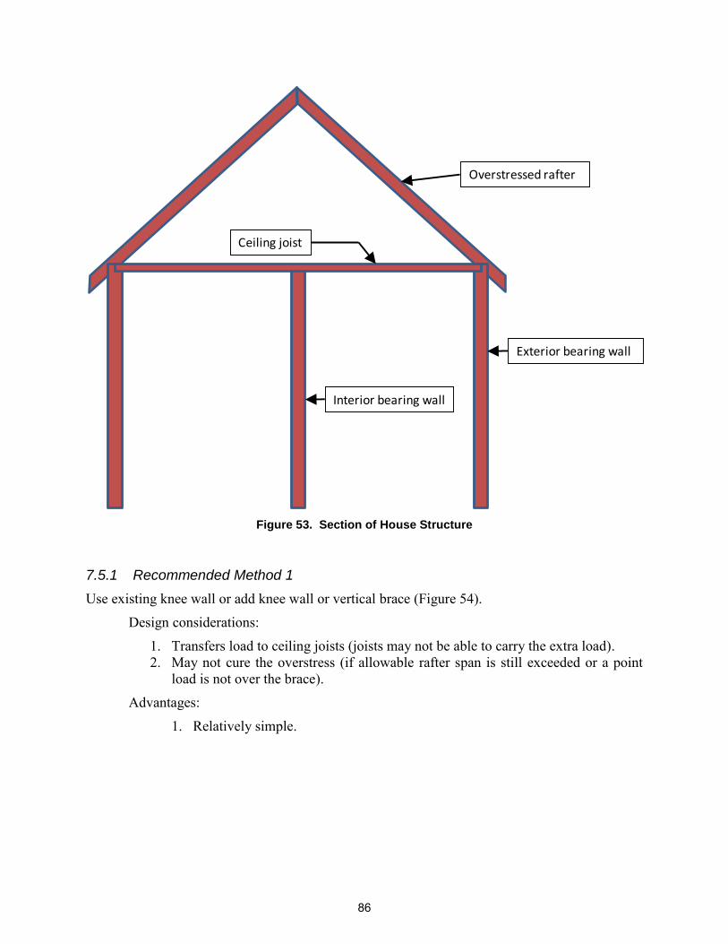
http://www.state.md.us or http://www.maryland.gov
County Government Pages – Building codes, business licenses, building permits, contractors‘ licenses, and home improvement licenses are issued and administered by county agencies as well. County Web sites often use the following URL format, substituting the 2 letter abbreviation for the county and state where you want to find information:
http://www.co.ba.md.us or http://www.baltimorecountymd.gov
An example of a state that has its own code requirements is the Wisconsin. These Wisconsin-specific codes are as follows:
Residential Code: Wisconsin Uniform Dwelling Code Comm. 20-25 Commercial Code: Wisconsin Commercial Building Code Comm. 60-66 Solar Energy Systems: Comm. 71
The local code can be found at: http://www.commerce.state.wi.us/SB/SB-DivCodesListing.html. How and where to obtain applicable permits can be found at: http://www.cityofmadison.com/Sustainability/City/madiSUN/.
1.2 Avoid Structural Element and/or Building System Failures
Many people think of a structural failure as one that is broadcast on the evening news or that results in catastrophic results (see Figures 1 and 2). However, this manual is designed to specifically address the less calamitous failures that violate building codes or quality construction practice.
Structural failures occur when a structure or structural element loses or potentially impairs its ability to support a load. Examples of common failures include excessive deflection in a
structural beam or sagging roof, inadequate connection strength, splitting of a top chord of a wood truss, or a roof penetration that causes a roof leak that can lead to degradation of a structural element. This document is intended to help installers properly evaluate and analyze support structures for the installation of solar equipment.
Figure 1. Roof Collapse Due to Excessive Snow Load
Figure 2. Truss Failure Due to Excessive Roof Load
13
To avoid failure, solar installers must not exceed a structure‘s maximum load-bearing capacity with the installation of a solar energy system. Strength failures and stability failures are two types of structural failure relevant to solar installers:
Strength failures relate to the pieces composing a structure. Stability failures relate to structural systems.
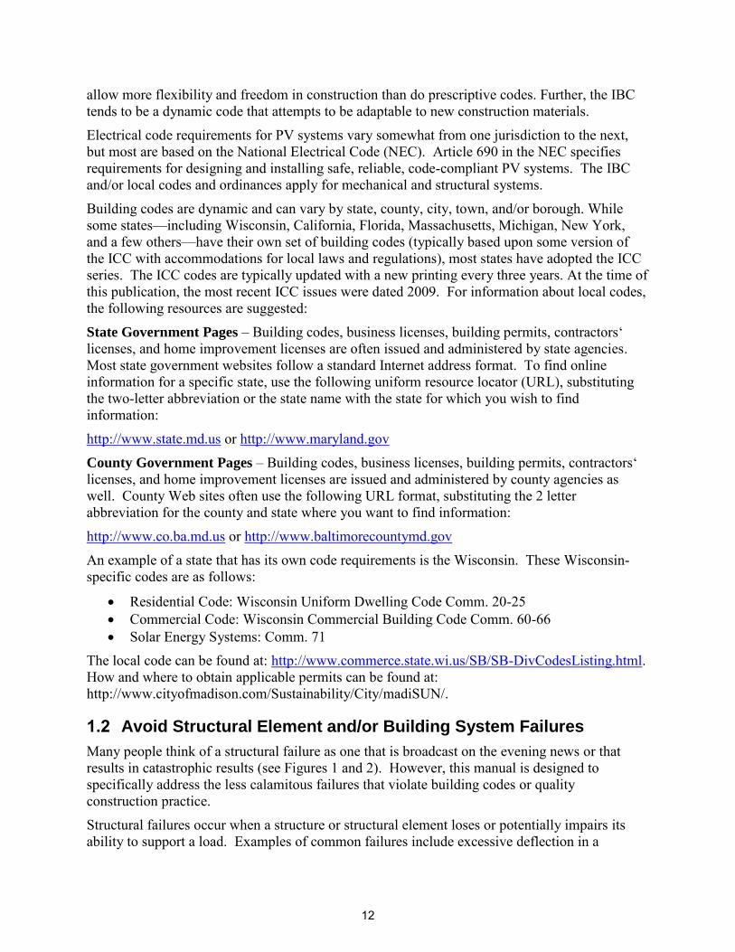
Strength failures include excessive bending, vertical shear, and horizontal shear. Bending is the most common type of strength failure (see Figure 3). A failure due to bending can result when applied stresses exceed the allowable bending strength of the structural member or when the resulting deflection exceeds the allowable deflection in that member. When a simple beam is loaded in flexure, the top side is in compression and the bottom side is in tension. If the beam is not supported in the lateral direction (i.e., perpendicular to the plane of bending), and the flexural load increases to a critical limit, the beam will fail due to lateral buckling of the compression flange. In wide-flange sections, if the compression flange buckles laterally, the cross section will also twist in torsion, resulting in a failure mode known as lateral-torsional buckling.
Figure 3. Bending in a Beam
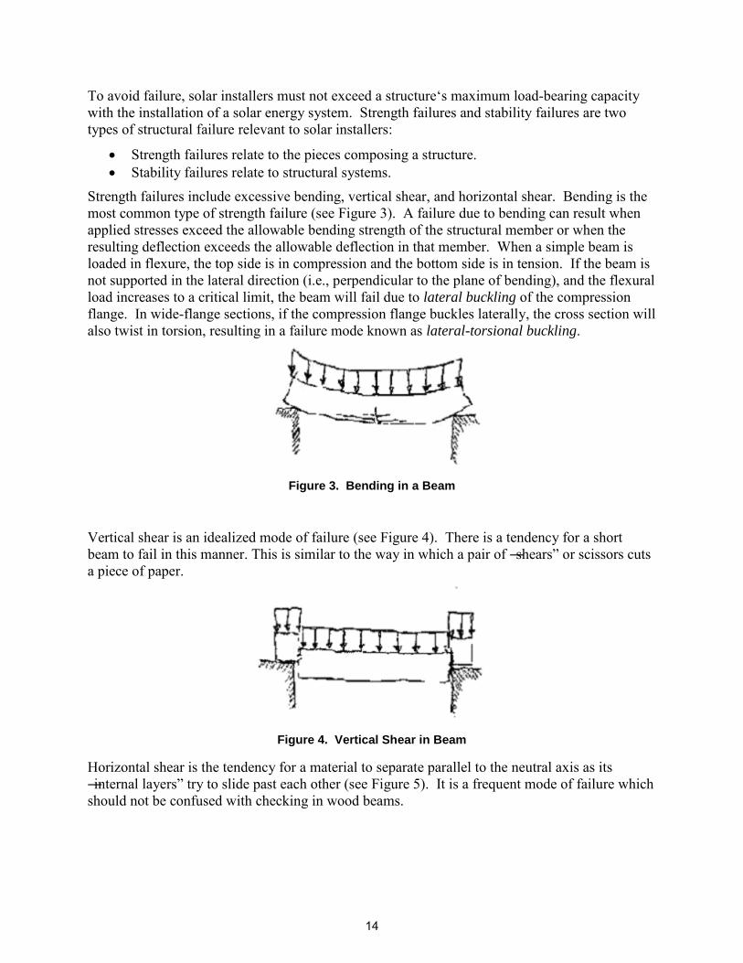
Vertical shear is an idealized mode of failure (see Figure 4). There is a tendency for a short beam to fail in this manner. This is similar to the way in which a pair of ―shears‖ or scissors cuts a piece of paper.
Figure 4. Vertical Shear in Beam
Horizontal shear is the tendency for a material to separate parallel to the neutral axis as its ―internal layers‖ try to slide past each other (see Figure 5). It is a frequent mode of failure which should not be confused with checking in wood beams.
Stability failures generally relate to structural systems. These failures can be caused by lateral loads from wind or seismic events. For individual members, examples include:
Columns fail due to elastic instability (i.e., column buckling) Beams fail due to lateral or lateral-torsional buckling
Elastic instability results in the buckling of a member (see Figure 6). This is characterized by a sudden failure of a structural member subjected to high compressive stresses. Actual compressive stress at the point of failure is less than the ultimate compressive stresses of the material. If the load on a column is applied through the center of gravity of its cross section, it is called an axial load. An eccentric load on a column or pile, which is non-symmetric with respect to the central axis, produces a bending moment in addition to the axial load. Eccentric loads promote buckling at a lower compressive stress due to the induced couple.
Figure 6. Axial Load in Column
1.3 Manual Overview
Structural Considerations for Solar Installers is designed to provide a comprehensive outline of structural considerations associated with simplified solar installations and to recommend a set of best practices installers can follow when assessing such considerations. Information in the manual comes from engineering and solar experts as well as case studies. The objectives of the manual are to ensure safety and structural durability for rooftop solar installations and to
potentially accelerate the permitting process by identifying and remedying structural issues prior to installation.
Section 2 provides a basic process flow chart through which installers can determine whether to engage a structural engineer or conduct a self-assessment of a building‘s structural integrity. The chart is intended to outline the general steps involved in an early assessment of a simplified installation and lays the groundwork for elements covered in subsequent sections of the manual.
Section 3 discusses recommended documentation, the Solar Installation Submittal Form (found in Appendix A).
Section 4 details considerations for evaluating the condition of a building‘s roof structure. The focus is on trusses, which are critical elements for support of roof loads. The section provides information about how to evaluate and remedy truss damage and manufacturing defects, bracing issues, cracks and knots, and general truss integrity.
Section 5 widens the scope of structural integrity to include loading issues and mechanics of building materials, primarily wood. The section includes detailed mathematical discussion and examples of statics, wood modification factors, and loading conditions. Section 4 also outlines the effects of roof slope on solar design, provides information about roof rafters and joists, and offers links to tools that installers can use to calculate load.
Section 6 of the manual delves into less visible but important connective elements that can affect structural integrity. The section offers detailed information about the importance of properly selected and installed nails, screws, bolts, connector plates, and fasteners. A critical theme of the section is how these connectors impact a roof structure‘s ability to carry load, which can have significant effect on the design and installation of solar panels.
Section 7 offers a set of solar installation best practices, designed to provide installers with a tool kit for evaluating structural integrity. Information in this section includes setback requirements, location and evaluation of roof structural members and attachments, and discussion about weatherproofing solar energy system attachments on various types of roofing materials. The section also provides detailed recommended methods for reinforcing overstressed rafters prior to completing a solar installation.
Information in the manual is supported by numerous tables, drawings, and links to additional tools.
16
FLOW CHART 2
This structural guidance is intended to apply only to simplified solar installations. A flow chart has been prepared to illustrate this point.
START Complete Installer
Assessment Checklist
Does roof qualify for expedited process?
yes
no
Structural Designer
Needed
Assess Structural Integrity Using Applicable Method
Prepare Documentation Submit Package
for Permitting
Review
Pass? no
yes
Modify design and/or
Reinforce (Structural
Designer May be Needed
iterate
Wood Joists or Beams
Wood Trusses
Does it meet criteria for simplified approval?
yes
no
Note: this flowchart only applies to installations on buildings less than
50,000 cubic feet. Larger buildings require a licensed architect or engineer.
17
This page is intentionally blank.
18
DOCUMENTATION 3
3.1 Solar Installation Submittal Form
It is recommended the solar installer complete a solar installation submittal form that summarizes existing conditions, planned solar deployment, and structural evaluation. This form should be submitted with the permit application to the local building authority to provide that authority confidence in the recommended solar energy system installation. This form is attached in Appendix A.
This manual applies to building volumes nominally less than 50,000 cubic feet. If structures are greater than this, a structural design/assessment should be performed by a professional trained in that field, such as a structural engineer or architect.
19
This page is intentionally blank.
20
ASSESS CONDITION OF ROOF STRUCTURE 4
The condition of the roof structure must be assessed before a rooftop solar energy system can be installed. This assessment should address whether the existing structure has excess capacity for additional loads due to a solar installation or if modifications are necessary for the installation.
4.1 Truss Integrity Inspection
Rafters or trusses that will support a solar energy system installation should be inspected prior to installation of that solar energy system. The size, spacing, and condition of rafters should all be assessed. Although assessing the integrity of a rafter is generally straightforward, trusses are often more difficult to inspect. The following section provides a summary of what should be considered during the pre-installation inspection.
It is recommended that a truss not be modified or repaired without the assistance of a qualified
structural engineer! Roof trusses are an assembly of wood pieces (commonly 2 × 4s) connected together with steel plates to form a unified structural member. A truss is similar to a common beam in that it supports loads across an open space. Besides the geometry, the biggest difference between a truss and solid beam is that each member (piece) of the truss must resist force in tension or compression parallel to the length of the member, while a solid beam supports the load and stresses in flexure.
It is important to understand that every member of a truss is essential for adequate performance. Thus any repairs, modifications, or damage to a truss member affects the entire truss and its ability to resist the loads placed on it. If a truss member is cut or removed, the entire truss becomes defective unless remedial work is performed to properly redistribute loads around the modified part of the truss. Cutting or removing a truss member has essentially the same effect as making a cut through the entire depth of a solid beam, such as a 2 × 12 floor joist. Roof trusses typically require lateral bracing, perpendicular to the plane (length) of the truss. This bracing should not be removed, especially for trusses with relatively long ―web‖ members.
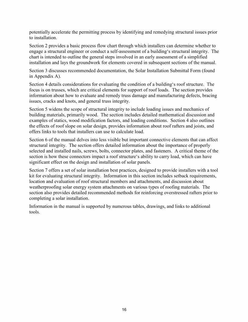
Residential roof trusses are commonly spaced at 24 inches. Clear space between bottom chords of adjacent trusses is then 22.5 inches. Most trusses are built by a truss manufacturer, though some are built on site. Truss manufacturers provide engineering to ensure that the truss can support the loads specified. Conversely, the load-carrying capacity of site-built trusses (see Figure 7) can be unknown. It is suggested that such trusses be evaluated by a qualified engineer prior to placing additional load on them, such as a solar installation.
21
Figure 7. Site-built Truss (Denise 2007)
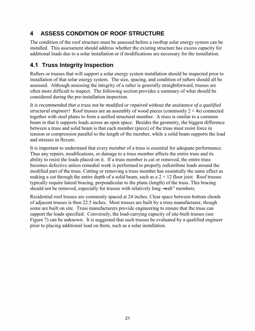
4.1.1 Damaged Truss Members
Damage can occur for many reasons, including manufacturing flaws, transporting mishaps, and improper installation. Of specific concern in this document is damage to a truss member that weakens it and thus decreases the load-carrying capacity. Damaged or improperly installed trusses are weak and may not support extreme snow or wind loads. Section R802.10.4 of the 2009 IRC states: ―Truss members shall not be cut, notched, drilled, spliced or otherwise altered in any way without the approval of a registered design professional.‖ Therefore, if damaged trusses are encountered, it is best to have a qualified structural engineer or architect evaluate the situation and/or design a repair.
Common fixes to damaged wood truss members include installing and securely connecting another wood member alongside the damaged member. The original steel connector plates used to connect wood elements within the truss can be damaged or inadvertently removed. These plates are important for the comprehensive strength of the truss. Plates can be reattached or, in some cases, larger plywood gusset plates can be installed to provide the same connection capacity.
4.1.2 Manufacturing Problems
Manufacturing of trusses in a factory setting generally allows for a high degree of quality control compared with those built in the field. Incorrectly manufactured trusses are not common, but can occur. Evaluation of the member size (member consistency); member quality (excessive knots, cracks, twisting, etc.); and quality, placement, and attachment of joint plates should be evaluated. A quick visual inspection is generally adequate for this.
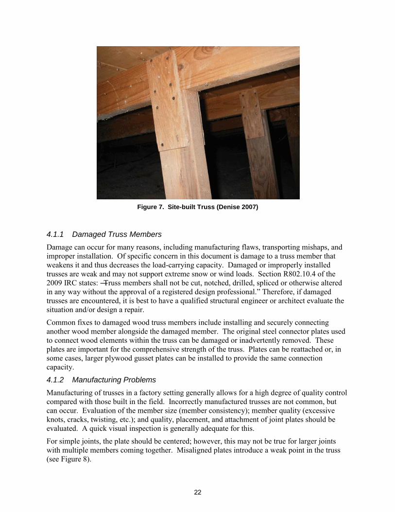
For simple joints, the plate should be centered; however, this may not be true for larger joints with multiple members coming together. Misaligned plates introduce a weak point in the truss (see Figure 8).
Metal connector plates are generally installed on each side of a joint. Plates can be unintentionally removed during transportation of the truss or improper handling during construction, or may never have been installed.
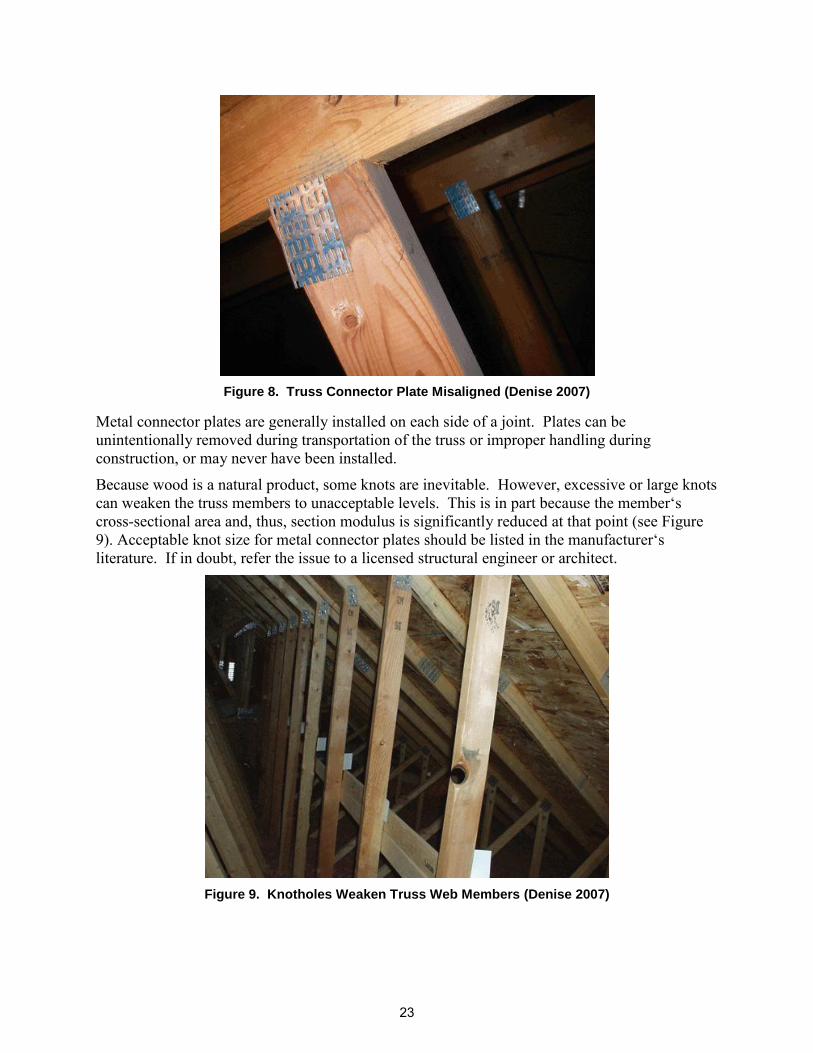
Because wood is a natural product, some knots are inevitable. However, excessive or large knots can weaken the truss members to unacceptable levels. This is in part because the member‘s cross-sectional area and, thus, section modulus is significantly reduced at that point (see Figure 9). Acceptable knot size for metal connector plates should be listed in the manufacturer‘s literature. If in doubt, refer the issue to a licensed structural engineer or architect.
Figure 9. Knotholes Weaken Truss Web Members (Denise 2007)
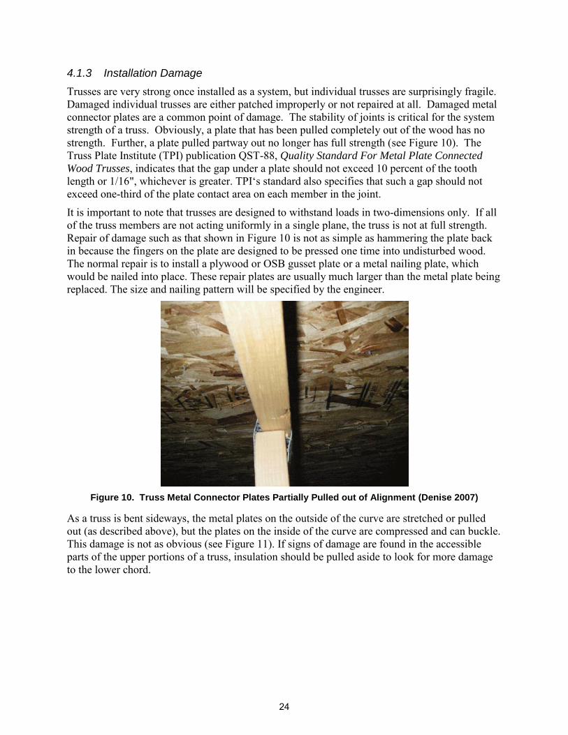
Trusses are very strong once installed as a system, but individual trusses are surprisingly fragile. Damaged individual trusses are either patched improperly or not repaired at all. Damaged metal connector plates are a common point of damage. The stability of joints is critical for the system strength of a truss. Obviously, a plate that has been pulled completely out of the wood has no strength. Further, a plate pulled partway out no longer has full strength (see Figure 10). The Truss Plate Institute (TPI) publication QST-88, Quality Standard For Metal Plate Connected
Wood Trusses, indicates that the gap under a plate should not exceed 10 percent of the tooth length or 1/16", whichever is greater. TPI‘s standard also specifies that such a gap should not exceed one-third of the plate contact area on each member in the joint.
It is important to note that trusses are designed to withstand loads in two-dimensions only. If all of the truss members are not acting uniformly in a single plane, the truss is not at full strength. Repair of damage such as that shown in Figure 10 is not as simple as hammering the plate back in because the fingers on the plate are designed to be pressed one time into undisturbed wood. The normal repair is to install a plywood or OSB gusset plate or a metal nailing plate, which would be nailed into place. These repair plates are usually much larger than the metal plate being replaced. The size and nailing pattern will be specified by the engineer.
Figure 10. Truss Metal Connector Plates Partially Pulled out of Alignment (Denise 2007)
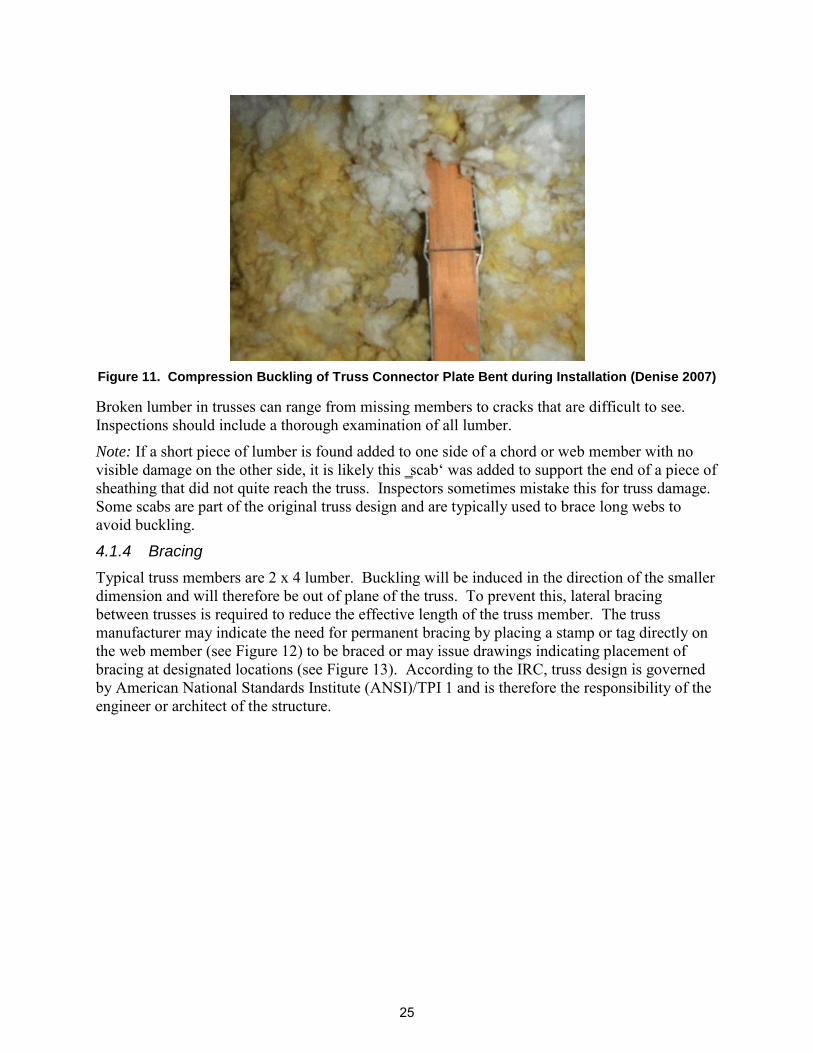
As a truss is bent sideways, the metal plates on the outside of the curve are stretched or pulled out (as described above), but the plates on the inside of the curve are compressed and can buckle. This damage is not as obvious (see Figure 11). If signs of damage are found in the accessible parts of the upper portions of a truss, insulation should be pulled aside to look for more damage to the lower chord.
Figure 11. Compression Buckling of Truss Connector Plate Bent during Installation (Denise 2007)
Broken lumber in trusses can range from missing members to cracks that are difficult to see. Inspections should include a thorough examination of all lumber.
Note: If a short piece of lumber is found added to one side of a chord or web member with no visible damage on the other side, it is likely this ‗scab‘ was added to support the end of a piece of sheathing that did not quite reach the truss. Inspectors sometimes mistake this for truss damage. Some scabs are part of the original truss design and are typically used to brace long webs to avoid buckling.
4.1.4 Bracing
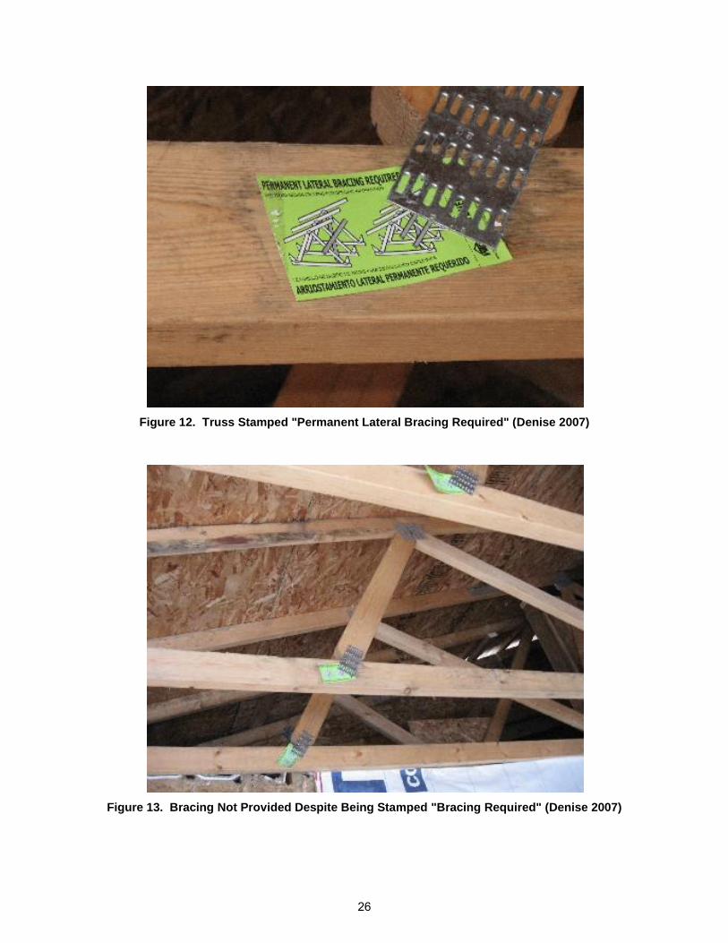
Typical truss members are 2 x 4 lumber. Buckling will be induced in the direction of the smaller dimension and will therefore be out of plane of the truss. To prevent this, lateral bracing between trusses is required to reduce the effective length of the truss member. The truss manufacturer may indicate the need for permanent bracing by placing a stamp or tag directly on the web member (see Figure 12) to be braced or may issue drawings indicating placement of bracing at designated locations (see Figure 13). According to the IRC, truss design is governed by American National Standards Institute (ANSI)/TPI 1 and is therefore the responsibility of the engineer or architect of the structure.
Figure 13. Bracing Not Provided Despite Being Stamped "Bracing Required" (Denise 2007)
26
While bracing that is required but not installed is an obvious problem, less obvious issues are discussed below as recommended in Building Component Safety Information (BCSI) 1-03 Guide
To Good Practice For Handling, Installation & Bracing Of Metal Plate Connected Wood
Trusses. BCSI 1-03 discusses both temporary and permanent bracing, along with other issues. Temporary bracing is used to stabilize the trusses during construction. Permanent bracing is bracing required after construction is completed and provides the structure‘s full strength. Bracing can be either continuous lateral restraint (CLR) or individual web member reinforcement, such as T-reinforcement.
Figure 14 demonstrates typical configurations. Some key elements to consider in bracing include the following:
Bracing lumber should be 2 x 4 stress-grade lumber unless otherwise specified by the designer.
Each connection should have at least two nails. CLR must be connected to a fixed point in the building (such as a shear wall
or roof plane) or it must be diagonally braced. This includes the top chords of the lower set of trusses set in a piggyback configuration.
CLR is not effective when the web pattern changes from one truss to the next (see Figure 15). T-reinforcement should be used instead.
T-reinforcement should be 90 percent of the length of the web member and nailed at 6" on center unless specified otherwise by the designer.
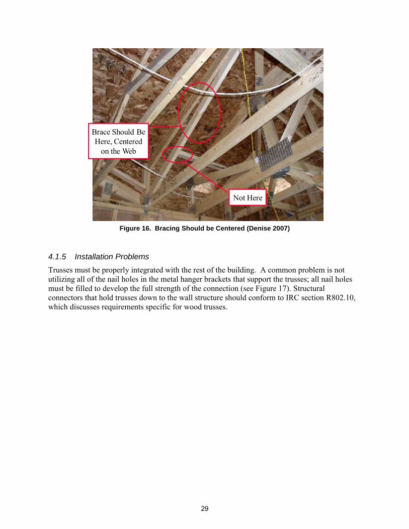
Bracing needs to be tight to the web member to be effective. CLR should be roughly centered in the span (see Figure 16). Note that some
web members may require more than one CLR. CLR should be installed so that it does not block any access hatch that may
exist. T-reinforcement must be continuous; it is not effective if spliced in the
middle. Gable end trusses sometimes require special bracing, particularly in high wind
Figure 16. Bracing Should be Centered (Denise 2007)
4.1.5 Installation Problems
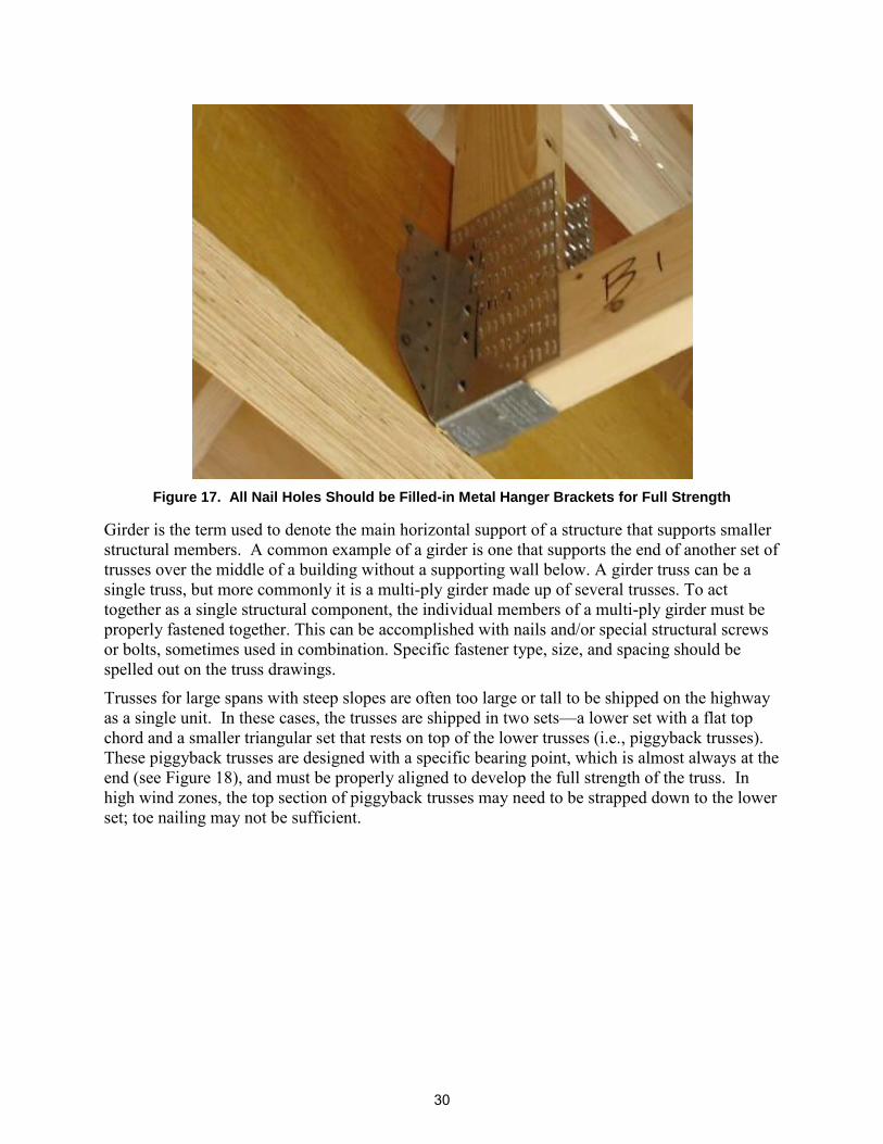
Trusses must be properly integrated with the rest of the building. A common problem is not utilizing all of the nail holes in the metal hanger brackets that support the trusses; all nail holes must be filled to develop the full strength of the connection (see Figure 17). Structural connectors that hold trusses down to the wall structure should conform to IRC section R802.10, which discusses requirements specific for wood trusses.
6/7/20103
Brace Should Be Here, Centered
on the Web
Not Here
29
Figure 17. All Nail Holes Should be Filled-in Metal Hanger Brackets for Full Strength
Girder is the term used to denote the main horizontal support of a structure that supports smaller structural members. A common example of a girder is one that supports the end of another set of trusses over the middle of a building without a supporting wall below. A girder truss can be a single truss, but more commonly it is a multi-ply girder made up of several trusses. To act together as a single structural component, the individual members of a multi-ply girder must be properly fastened together. This can be accomplished with nails and/or special structural screws or bolts, sometimes used in combination. Specific fastener type, size, and spacing should be spelled out on the truss drawings.
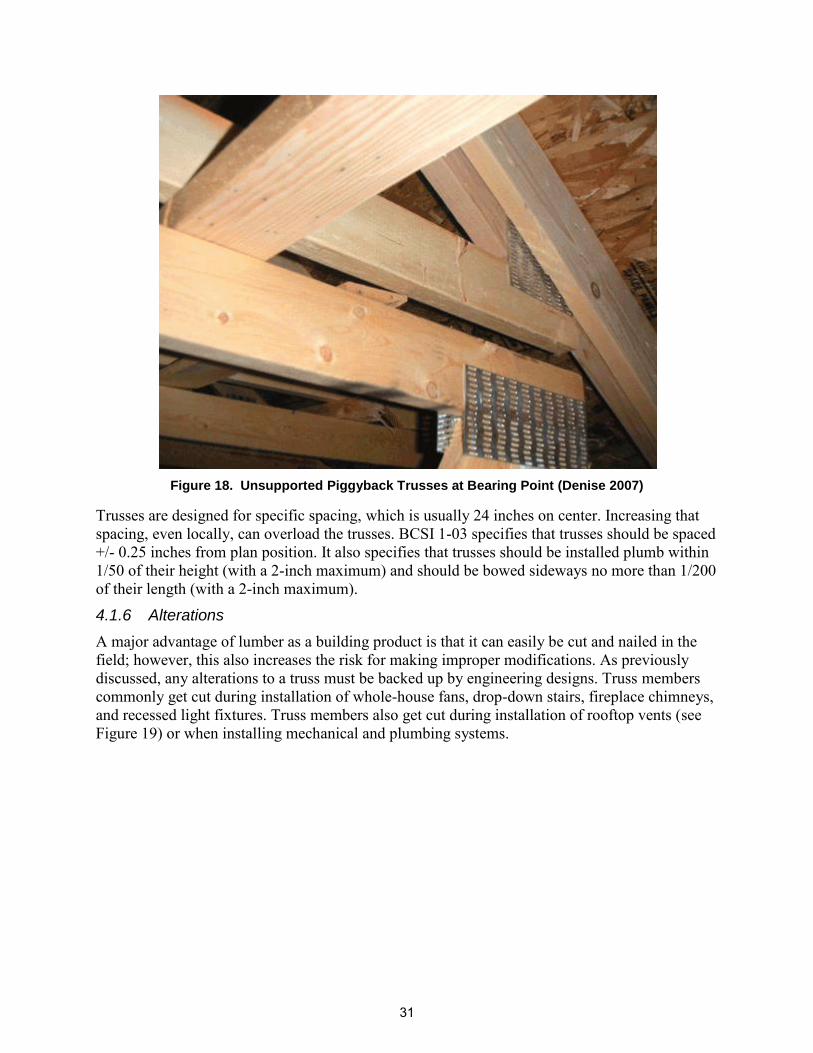
Trusses for large spans with steep slopes are often too large or tall to be shipped on the highway as a single unit. In these cases, the trusses are shipped in two sets—a lower set with a flat top chord and a smaller triangular set that rests on top of the lower trusses (i.e., piggyback trusses). These piggyback trusses are designed with a specific bearing point, which is almost always at the end (see Figure 18), and must be properly aligned to develop the full strength of the truss. In high wind zones, the top section of piggyback trusses may need to be strapped down to the lower set; toe nailing may not be sufficient.
30
Figure 18. Unsupported Piggyback Trusses at Bearing Point (Denise 2007)
Trusses are designed for specific spacing, which is usually 24 inches on center. Increasing that spacing, even locally, can overload the trusses. BCSI 1-03 specifies that trusses should be spaced +/- 0.25 inches from plan position. It also specifies that trusses should be installed plumb within 1/50 of their height (with a 2-inch maximum) and should be bowed sideways no more than 1/200 of their length (with a 2-inch maximum).
4.1.6 Alterations
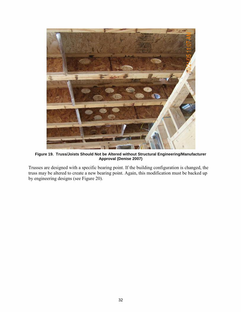
A major advantage of lumber as a building product is that it can easily be cut and nailed in the field; however, this also increases the risk for making improper modifications. As previously discussed, any alterations to a truss must be backed up by engineering designs. Truss members commonly get cut during installation of whole-house fans, drop-down stairs, fireplace chimneys, and recessed light fixtures. Truss members also get cut during installation of rooftop vents (see Figure 19) or when installing mechanical and plumbing systems.
Figure 19. Truss/Joists Should Not be Altered without Structural Engineering/Manufacturer
Approval (Denise 2007)
Trusses are designed with a specific bearing point. If the building configuration is changed, the truss may be altered to create a new bearing point. Again, this modification must be backed up by engineering designs (see Figure 20).
32
Figure 20. Typical Engineered Truss Repair
Section 802.10.4 of the 2009 IRC specifies: ―Alterations resulting in the addition of load (e.g., HVAC equipment, water heater) that exceeds the design load for the truss shall not be permitted without verification that the truss is capable of supporting such additional loading.‖ Besides rooftop solar installations, common change-of-loading cases include heavier roofing materials
33
(such as clay or concrete tiles) being substituted for asphalt shingles during re-roofing. The roofer should have an engineer verify that this increased loading is safe.
34
ASSESS STRUCTURAL INTEGRITY 5This section provides an overview of structural engineering concepts and design elements.
5.1 Proper Loading for Solar Panels
Residential applications typically involve a pitched roof in which solar panels are mounted parallel to the roof pitch. The gravity loads of the solar panels can magnify the uniform loads existing on the roof by concentrating them as point loads. The same holds true for wind loading, as the wind uplift is accumulated through the solar array and directed to the posts that support the solar panel. Also, depending on the roof geometry, the solar panel may act as a sail and catch wind from under the panel, creating very high uplift loads.
In some applications, solar panels are put on flat roofs. To achieve higher efficiency, the photovoltaic panels will be posted to the roof such that the panels are at a pitch angled toward the sun. With this geometry, snow can accumulate on the solar array, but can also slide off the panel and create a drift on the low side of the panel. Further, wind can create many different loading scenarios in roof applications.
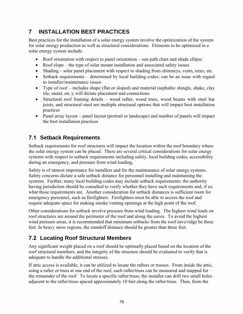
Yet another concern is that solar panels are often attached to rafters or trusses with lag screws that must land in the center of a 1.5-inch-wide top chord. Depending on the diameter of the connector, a repair may be required due to the section loss of the wood in the top chord. It is highly recommended that all connections of solar panels be made into blocking that is run between trusses, thus avoiding potential damage to the structural integrity of the truss or rafter. This not only prevents the drilling of trusses, but also distributes any point loads between two trusses and decreases the severity of any repairs.
A summary of the basics of structural engineering is warranted at this point to provide the solar installer a cursory understanding and appreciation for mechanics of materials and statics involved in the design and analysis of structural elements supporting solar installations.
5.2 Mechanics of Materials
In materials science, the strength of a material is its ability to withstand an applied stress without failure. Yield strength refers to the point on the engineering stress-strain curve beyond which the material begins deformation that cannot be reversed upon removal of the loading (see Point C, Figure 22). Ultimate strength refers to the point on the engineering stress-strain curve corresponding to the maximum stress (see Point D, Figure 22). The applied stress may be tensile, compressive, or shear.
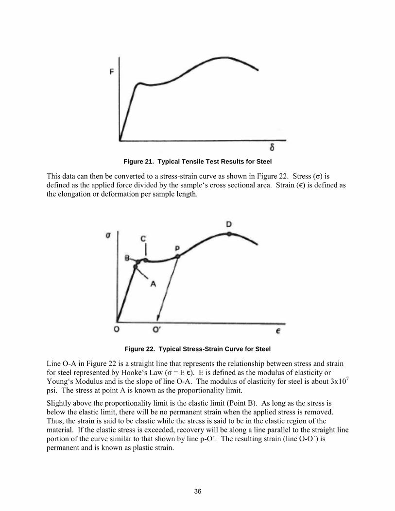
Many material properties can be derived from a standard tensile test. This involves a material sample loaded with a force (F) axially in tension whereby the elongation (δ) is measured as the load is increased. Figure 21 represents a typical graphical representation of this test for steel.
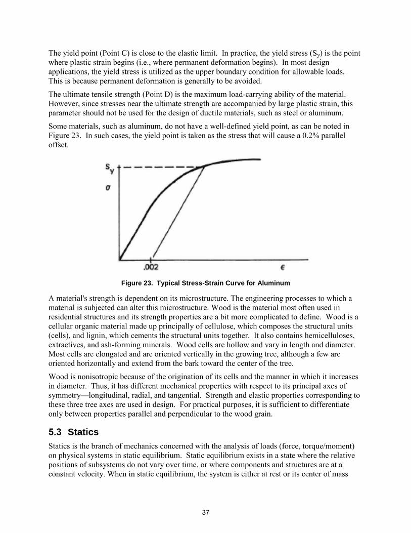
This data can then be converted to a stress-strain curve as shown in Figure 22. Stress (σ) is defined as the applied force divided by the sample‘s cross sectional area. Strain (ϵ) is defined as the elongation or deformation per sample length.
Figure 22. Typical Stress-Strain Curve for Steel
Line O-A in Figure 22 is a straight line that represents the relationship between stress and strain for steel represented by Hooke‘s Law (σ = E ϵ). E is defined as the modulus of elasticity or Young‘s Modulus and is the slope of line O-A. The modulus of elasticity for steel is about 3x10⁷ psi. The stress at point A is known as the proportionality limit.
Slightly above the proportionality limit is the elastic limit (Point B). As long as the stress is below the elastic limit, there will be no permanent strain when the applied stress is removed. Thus, the strain is said to be elastic while the stress is said to be in the elastic region of the material. If the elastic stress is exceeded, recovery will be along a line parallel to the straight line portion of the curve similar to that shown by line p-O΄. The resulting strain (line O-O΄) is permanent and is known as plastic strain.
36
The yield point (Point C) is close to the elastic limit. In practice, the yield stress (Sy) is the point where plastic strain begins (i.e., where permanent deformation begins). In most design applications, the yield stress is utilized as the upper boundary condition for allowable loads. This is because permanent deformation is generally to be avoided.
The ultimate tensile strength (Point D) is the maximum load-carrying ability of the material. However, since stresses near the ultimate strength are accompanied by large plastic strain, this parameter should not be used for the design of ductile materials, such as steel or aluminum.
Some materials, such as aluminum, do not have a well-defined yield point, as can be noted in Figure 23. In such cases, the yield point is taken as the stress that will cause a 0.2% parallel offset.
Figure 23. Typical Stress-Strain Curve for Aluminum
A material's strength is dependent on its microstructure. The engineering processes to which a material is subjected can alter this microstructure. Wood is the material most often used in residential structures and its strength properties are a bit more complicated to define. Wood is a cellular organic material made up principally of cellulose, which composes the structural units (cells), and lignin, which cements the structural units together. It also contains hemicelluloses, extractives, and ash-forming minerals. Wood cells are hollow and vary in length and diameter. Most cells are elongated and are oriented vertically in the growing tree, although a few are oriented horizontally and extend from the bark toward the center of the tree.
Wood is nonisotropic because of the origination of its cells and the manner in which it increases in diameter. Thus, it has different mechanical properties with respect to its principal axes of symmetry—longitudinal, radial, and tangential. Strength and elastic properties corresponding to these three tree axes are used in design. For practical purposes, it is sufficient to differentiate only between properties parallel and perpendicular to the wood grain.
5.3 Statics
Statics is the branch of mechanics concerned with the analysis of loads (force, torque/moment) on physical systems in static equilibrium. Static equilibrium exists in a state where the relative positions of subsystems do not vary over time, or where components and structures are at a constant velocity. When in static equilibrium, the system is either at rest or its center of mass
moves at constant velocity. By Newton‘s first law, this situation implies that the net force and net torque (also known as moment of force) on every body in the system is zero. From this constraint, such quantities as stress or pressure can be derived. The net forces equaling zero is known as the first condition for equilibrium, and the net torque equaling zero is known as the second condition for equilibrium.
This can be mathematically represented as follows, where the components of a force are:
Fx = F (cos θx)
Fy = F (cos θy)
Fz = F (cos θz)
And FR = √
Figure 24. Force Components
To satisfy the first condition of equilibrium, the sum of the forces in a given direction is equal to zero:
Σ Fx = 0
Σ Fy = 0
Σ Fz = 0
A force which would cause an object to rotate is said to contribute a moment to the object. The magnitude of a moment is the product of the force and its moment arm.
And to satisfy the second condition of equilibrium:
Σ Mx = 0
Σ My = 0
Σ Mz = 0
5.4 Wood Section Properties and Design Values
Section properties of a structural element such as a 2 x 4 must be determined prior to the analysis of a member. Also, types of loads and loading conditions must be understood. Buildings or other structures and all parts thereof should be designed to adequately support all loads, including dead loads that may reasonably be expected to affect the structure during its service life. These loads should be as stipulated by the governing building code or, in the absence of such a code, the loads, forces, and combination of loads should be in accordance with accepted engineering practice for the geographical area under consideration (American Institute of Timber Construction [AITC] 1985).
Section properties are important when it comes to the ability of a structural element to withstand applied loads. A brief description of the determination of section properties is presented here. For a rectangular piece of wood as shown in Figure 26, its neutral axis is defined by x-x.
39
Figure 26. Rectangular Cross-section
The cross-sectional area (A) of a rectangle is simply calculated by multiplying the width (b) by the height (h):
A = bh
It is important to note that the advertised dimensions of a wood element are not quite accurate. For example, a common 2 x 4 stud is not 2 inches by 4 inches, but typically 1.5 inches by 3.5 inches, with an area of 5.25 square inches. Refer to Table 1 below for typical section properties for common wood elements.
The moment of inertia of a structural element provides resistance to bending. The moment of inertia of an object about a given axis describes how difficult it is to change its angular motion about that axis. Therefore, it encompasses not just how much mass the object has overall, but how far each bit of mass is from the axis. The farther out the object‘s mass is, the more rotational inertia the object has, and the more force is required to change its rotation rate. The moment of inertia (I) about the neutral axis of the cross section of a beam is the sum of the products of each of its elementary areas of mass by the square of their distance from the neutral axis of the section. The neutral axis in Figure 26 is X-X. The moment of inertia of a section is utilized to calculate bending stresses and deflections in a beam. Specifically for a rectangle as shown in Figure 26, the moment of inertia is calculated as follows:
Ixx = bh3/12
The section modulus of a member is often used to calculate the bending stress in that member. The section modulus (S) is the moment of inertia divided by the distance from the neutral axis to the outside of the section. The section modulus is utilized to calculate the allowable bending stress in a beam. For the rectangular cross-section shown in Figure 26, the section modulus is calculated as follows:
Sxx = bh2/6
h
b
x x
40
Table 1. Common Section Properties for Wood Elements
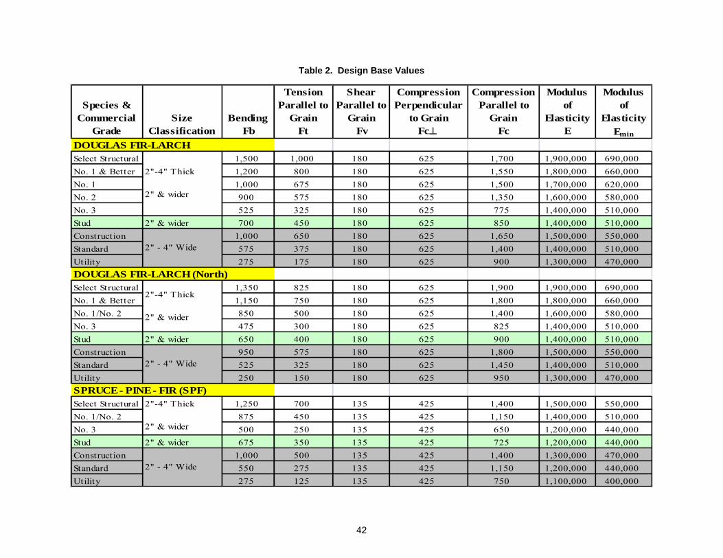
Wood strength and section properties are dependent upon the type or species of wood (e.g., Northern Pine or Douglas Fir), grade (e.g., select structural or stud), the type of stress applied (e.g., tension parallel to grain or horizontal shear), and size classification (e.g., 2-inch thick or decking). There are multiple sources that contain design properties for wood, such as the National Design Specification for Wood Construction, National Design Specification [NDS]-2005). Table 2 provides an example of design base values for Douglas Fir-Larch. The table for Douglas Fir-Larch is reproduced from the Design Values for Wood Construction, a supplement of the ANSI/ American Forest & Paper Association (AF&PA) NDS-2005 NDS for Wood Construction with Commentary.
PROPERTIES OF STRUCTURAL LUMBER
Sectional Properties of Standard Dressed (S4S) Lumber Sizes
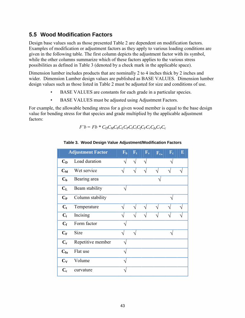
Design base values such as those presented Table 2 are dependent on modification factors. Examples of modification or adjustment factors as they apply to various loading conditions are given in the following table. The first column depicts the adjustment factor with its symbol, while the other columns summarize which of these factors applies to the various stress possibilities as defined in Table 3 (denoted by a check mark in the applicable space).
Dimension lumber includes products that are nominally 2 to 4 inches thick by 2 inches and wider. Dimension Lumber design values are published as BASE VALUES. Dimension lumber design values such as those listed in Table 2 must be adjusted for size and conditions of use.
• BASE VALUES are constants for each grade in a particular species.
• BASE VALUES must be adjusted using Adjustment Factors.
For example, the allowable bending stress for a given wood member is equal to the base design value for bending stress for that species and grade multiplied by the applicable adjustment factors:
F’b = Fb * CDCMCbCLCPCtCiCfCFCrCfuCVCc
Table 3. Wood Design Value Adjustment/Modification Factors
Adjustment Factor Fb Ft Fv Fc+ Fc E
CD Load duration √ √ √ √
CM Wet service √ √ √ √ √ √
Cb Bearing area √
CL Beam stability √
CP Column stability √
Ct Temperature √ √ √ √ √ √
Ci Incising √ √ √ √ √ √
Cf Form factor √
CF Size √ √ √
Cr Repetitive member √
Cfu Flat use √
CV Volume √
Cc curvature √
43
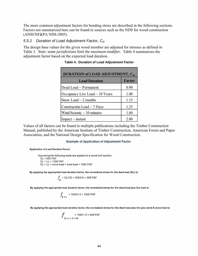
The more common adjustment factors for bending stress are described in the following sections. Factors not summarized here can be found in sources such as the NDS for wood construction (ANSI/NF&PA NDS-2005).
5.5.1 Duration of Load Adjustment Factor, CD
The design base values for the given wood member are adjusted for stresses as defined in Table 3. Note: some jurisdictions limit the maximum modifier. Table 4 summarizes the adjustment factor based on the expected load duration.
Table 4. Duration of Load Adjustment Factor
Factor
0.90
1.001.15
1.251.602.00
Wind/Seismic ~ 10 minutesImpact ~ instant
DURATION of LOAD ADJUSTMENT, CD
Load Duration
Dead Load ~ Permanent
Occupancy Live Load ~ 10 YearsSnow Load ~ 2 months
Construction Load ~ 7 Days
Values of all factors can be found in multiple publications including the Timber Construction Manual, published by the American Institute of Timber Construction, American Forest and Paper Association, and the National Design Specification for Wood Construction.
44
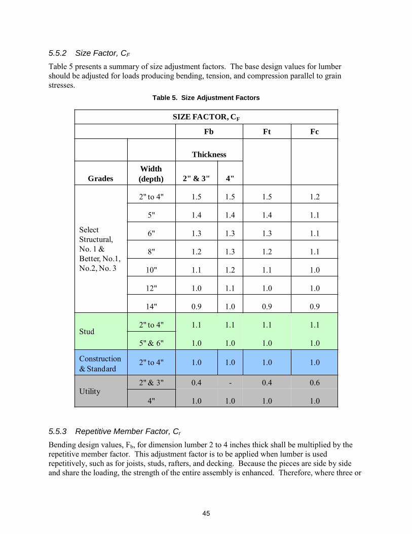
5.5.2 Size Factor, CF
Table 5 presents a summary of size adjustment factors. The base design values for lumber should be adjusted for loads producing bending, tension, and compression parallel to grain stresses.
Table 5. Size Adjustment Factors
5.5.3 Repetitive Member Factor, Cr
Bending design values, Fb, for dimension lumber 2 to 4 inches thick shall be multiplied by the repetitive member factor. This adjustment factor is to be applied when lumber is used repetitively, such as for joists, studs, rafters, and decking. Because the pieces are side by side and share the loading, the strength of the entire assembly is enhanced. Therefore, where three or
more members are adjacent or are not more than 24 inches on center and are joined by a floor, roof, or other load-distributing elements, the bending strength base design value can be increased by 1.15 for repetitive member use. To summarize:
• Cr = 1.15, if:
• Three (3) or more members
• Joined by floor, roof, or other load-distributing elements
• Members are used as joists, truss chords, rafters, studs, planks, and decking
• Members are spaced less than or equal to 24 inches on centers.
5.5.4 Wet Service Factor, CM
If the moisture content of the wood exceeds 19 percent for an extended time period, the wet service factor applies to all design base values. This factor is to be used only if the wood is exposed for an extended period of time, not periodically. Note: This factor does not generally
apply to rooftop applications because the roof wood structure should not be exposed to elevated
moisture conditions for extended periods of time.
5.5.5 Flat Use Factor, Cfu
When dimension lumber is used flatwise (load applied to wide face), the bending design value, Fb, shall also be multiplied by the flat use factor shown in Table 6.
Buildings and other structures, including all components, are designed to safely support all loads that reasonably may be applied during the life of that structure. The addition of solar installations on a new or existing structure must not compromise the structure‘s safety for the duration of the structure. The loads shall be accounted for in the design and analyses as stipulated by the governing building code or, in the absence of such a code, the loads, forces, and combination of loads shall be in accordance with accepted engineering practice for the geographical area under consideration.
Dead loads are defined as the vertical loads due to all permanent structural and nonstructural components of a structure such as walls, floors, partitions, stairways, and fixed service
46
equipment. The actual weights of dead loads should be used if available. Examples of dead loads can be found in publications such as the American Society of Civil Engineers‘ (ASCE‘s) ASCE 7-05. A few examples of typical dead loads are provided in Appendix D.
Live loads are defined as the loads superimposed by the use and occupancy of the building or structure, exclusive of wind, snow, earthquake, or dead loads. The minimum roof live load for a given structure should be stipulated by the governing building code. In design, these live loads should represent the designer‘s determination of the particular service requirements for that structure. Roof live loads include those produced during maintenance activities and during the life of the structure by moveable objects and people. The utilized live loads must include an adequate allowance for ordinary impact conditions.
Snow loads vary by geographic area. Design snow loads for roofs shall be the greater of that set forth in applicable building codes or in ASCE 7-05. When using the figures and tables in ASCE 7-05, special attention should be paid to areas at significant elevations where localized weather conditions can significantly increase snow loads. In this case, the ground snow loads shall be based on an extreme value statistical analysis of available data in the vicinity of the site using a 2% annual probability of being exceeded (50-year mean recurrence interval). The procedures outlined in ASCE 7-05 for determining the roof snow load for flat roofs, sloped roofs, curved roofs, unbalanced snow loads, drift loads, roof projections, sliding snow, rain-on-snow surcharge load, ponding potential, and existing roofs shall follow those prescribed in ASCE 7-05.
Buildings and other structures, including wind force-resisting systems and components/cladding thereof, shall be designed and constructed to resist applicable wind loads. The design wind loads for buildings and other structures, including wind force resisting systems and components/cladding thereof, shall be determined using one of the following procedures:
1. Method 1. Simplified Procedure for buildings and/or structural elements as specified in ASCE 7-05 for buildings and/or structural elements meeting requirements specified in ASCE 7-05;
2. Method 2. Analytical Procedure for buildings and/or structural elements as specified in ASCE 7-05 for buildings and/or structural elements meeting requirements specified in ASCE 7-05;
3. Method 3. Wind Tunnel Procedure as specified in ASCE 7-05.
Wind loads for solar panels or supports shall not be less than a net pressure of 10 lb/ft2 acting in either direction normal to the surface.
Earthquake loads shall be taken into account in any solar installation where applicable. For most regions of the United States, wind loads are greater than those imposed by an earthquake. However, there are some locations where earthquake loads may be greater. The most restrictive of applicable building codes or procedures outlined in ASCE 7-05 for determination of earthquake loads shall be followed if it is determined that earthquake loads apply to the site.
The load combination and load factors described in ASCE 7-05 shall be employed. Depending on whether strength or allowable stress design is used for the design and/or analysis, these combinations/factors vary. The following are load combinations utilized by the allowable stress design methodology:
1. D + F
2. D + H + F + L + T
47
3. D + H + F + (Lr or S or R)
4. D + H + F + 0.75(L + T ) + 0.75(Lr or S or R)
5. D + H + F + (W or 0.7E)
6. D + H + F + 0.75(W or 0.7E) + 0.75L + 0.75(Lr or S or R)
7. 0.6D + W + H
8. 0.6D + 0.7E + H
where: D = dead load E = earthquake load F = load due to fluids with well-defined pressures and maximum heights H = load due to lateral earth pressure, ground water pressure, or pressure of
bulk materials (generally zero for roof applications) L = live load Lr = roof live load R = rain load S = snow load T = self-straining force (generally zero for roof applications) W = wind load
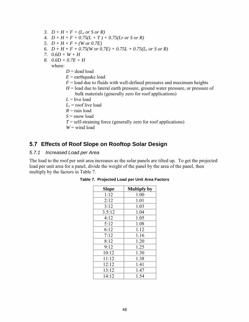
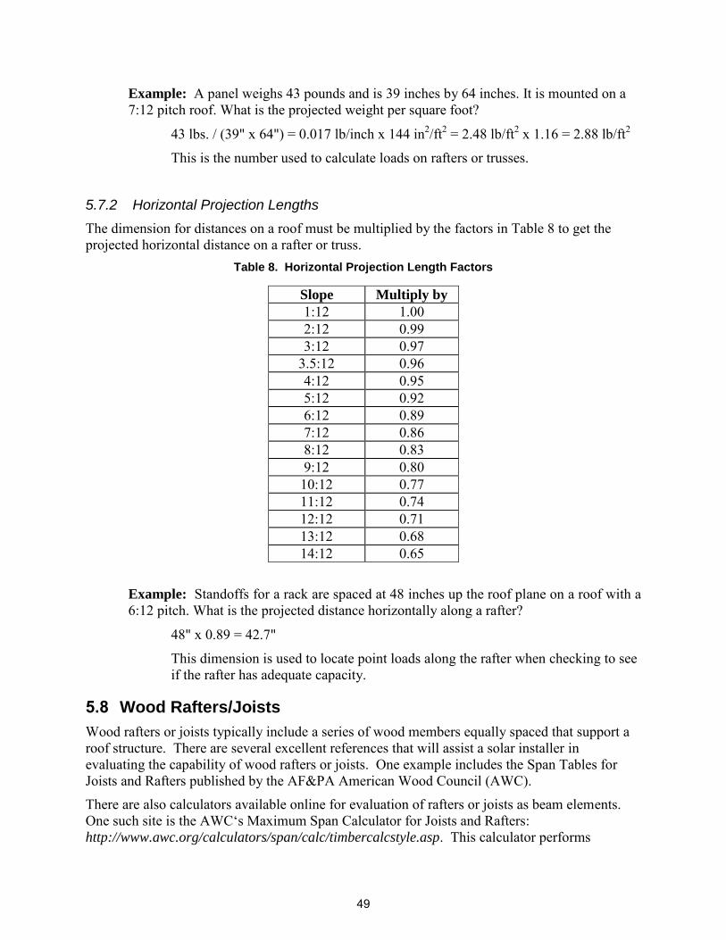
5.7 Effects of Roof Slope on Rooftop Solar Design
5.7.1 Increased Load per Area
The load to the roof per unit area increases as the solar panels are tilted up. To get the projected load per unit area for a panel, divide the weight of the panel by the area of the panel, then multiply by the factors in Table 7.
Example: Standoffs for a rack are spaced at 48 inches up the roof plane on a roof with a 6:12 pitch. What is the projected distance horizontally along a rafter?
48" x 0.89 = 42.7"
This dimension is used to locate point loads along the rafter when checking to see if the rafter has adequate capacity.
5.8 Wood Rafters/Joists
Wood rafters or joists typically include a series of wood members equally spaced that support a roof structure. There are several excellent references that will assist a solar installer in evaluating the capability of wood rafters or joists. One example includes the Span Tables for Joists and Rafters published by the AF&PA American Wood Council (AWC).
There are also calculators available online for evaluation of rafters or joists as beam elements. One such site is the AWC‘s Maximum Span Calculator for Joists and Rafters: http://www.awc.org/calculators/span/calc/timbercalcstyle.asp. This calculator performs
calculations for ALL species and grades of commercially available softwood and hardwood lumber as found in the NDS 2005 Supplement. Joists and rafter spans for common loading conditions can be determined. A ―span options‖ calculator allows selection of multiple species and grades for comparison purposes. This calculator may or may not be applicable for use in the analysis of existing joists and rafters for the installation of a new solar energy system. This determination should be made on a case-by-case basis.
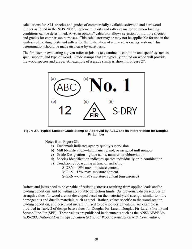
The first step in evaluating a given rafter or joist is to examine its condition and specifics such as span, support, and type of wood. Grade stamps that are typically printed on wood will provide the wood species and grade. An example of a grade stamp is shown in Figure 27:
Figure 27. Typical Lumber Grade Stamp as Approved by ALSC and its Interpretation for Douglas
Fir Lumber
Notes from Figure 23: a) Trademark indicates agency quality supervision. b) Mill Identification—firm name, brand, or assigned mill number c) Grade Designation—grade name, number, or abbreviation d) Species Identification indicates species individually or in combination e) Condition of Seasoning at time of surfacing.
S-DRY – 19% max. moisture content MC 15 – 15% max. moisture content S-GRN – over 19% moisture content (unseasoned)
Rafters and joists need to be capable of resisting stresses resulting from applied loads and/or loading conditions and be within acceptable deflection limits. As previously discussed, design strength values for wood are not developed based on the material yield strength similar to more homogenous and ductile materials, such as steel. Rather, values specific to the wood section, loading condition, and perceived use are utilized to develop design values. An example is provided in Table 2 of design base values for Douglas Fir-Larch, Douglas Fir-Larch (North) and Spruce-Pine-Fir (SPF). These values are published in documents such as the ANSI/AF&PA‘s
NDS-2005 National Design Specification (NDS) for Wood Construction with Commentary.
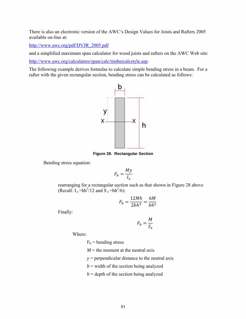
The following example derives formulas to calculate simple bending stress in a beam. For a rafter with the given rectangular section, bending stress can be calculated as follows:
Figure 28. Rectangular Section
Bending stress equation:
rearranging for a rectangular section such as that shown in Figure 28 above (Recall: I x =bh3/12 and S x =bh2/6):
The calculated bending stress of a given rafter can then be compared to the allowable bending stress for the wood member, utilizing the base design value with applicable adjustment factors. If the modified allowable value is greater than the calculated bending stress, assuming no other stress conditions apply, the member is adequate to withstand the applied bending stress. Refer to Appendix B for multiple examples.
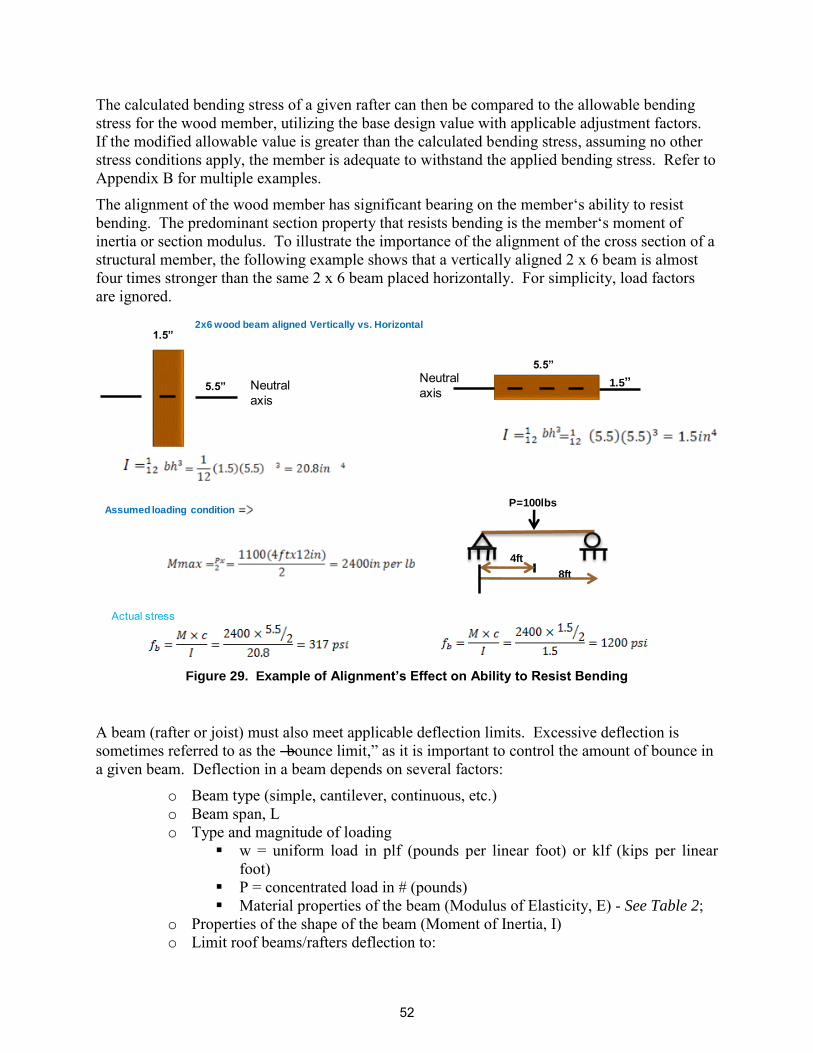
The alignment of the wood member has significant bearing on the member‘s ability to resist bending. The predominant section property that resists bending is the member‘s moment of inertia or section modulus. To illustrate the importance of the alignment of the cross section of a structural member, the following example shows that a vertically aligned 2 x 6 beam is almost four times stronger than the same 2 x 6 beam placed horizontally. For simplicity, load factors are ignored.
Figure 29. Example of Alignment’s Effect on Ability to Resist Bending
A beam (rafter or joist) must also meet applicable deflection limits. Excessive deflection is sometimes referred to as the ―bounce limit,‖ as it is important to control the amount of bounce in a given beam. Deflection in a beam depends on several factors:
o Beam type (simple, cantilever, continuous, etc.) o Beam span, L o Type and magnitude of loading
w = uniform load in plf (pounds per linear foot) or klf (kips per linear foot)
P = concentrated load in # (pounds) Material properties of the beam (Modulus of Elasticity, E) - See Table 2;
o Properties of the shape of the beam (Moment of Inertia, I) o Limit roof beams/rafters deflection to:
2x6 wood beam aligned Vertically vs. Horizontal1.5”
5.5” Neutralaxis
Neutralaxis
5.5”
1.5”
Assumed loading conditionP=100lbs
4ft
8ft
Actual stress
52
Live Load deflection = L/360 ( DLL = L/360) Total Load deflection = L/240 (D = L/240)
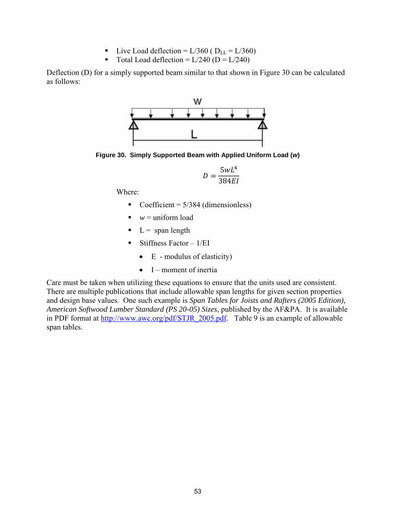
Deflection (D) for a simply supported beam similar to that shown in Figure 30 can be calculated as follows:
Figure 30. Simply Supported Beam with Applied Uniform Load (w)
Where:
Coefficient = 5/384 (dimensionless)
w = uniform load
L = span length
Stiffness Factor – 1/EI
E - modulus of elasticity)
I – moment of inertia Care must be taken when utilizing these equations to ensure that the units used are consistent. There are multiple publications that include allowable span lengths for given section properties and design base values. One such example is Span Tables for Joists and Rafters (2005 Edition), American Softwood Lumber Standard (PS 20-05) Sizes, published by the AF&PA. It is available in PDF format at http://www.awc.org/pdf/STJR_2005.pdf. Table 9 is an example of allowable span tables.
The following example provides an analysis of a wood beam or rafter that spans 12 feet and carries a combined dead and roof live load of 350 pounds per linear foot. The beam material is Douglas Fir Larch #2. The example demonstrates how to determine the minimum acceptable size or section properties for the beam.
Figure 31. Minimum Acceptable Beam Size or Section Example
Step 1: Find the maximum bending moment.
From Figure 26, the moment, M, for a uniformly loaded beam is:
Step 2: Find the tabulated value of F b for Douglas Fir-Larch #2 (Table 2):
Step 3: Determine allowable bending stress, :
Use CD = 1.25 (Load provided includes both DL & LL) Since the beam size is unknown, Assume value of CF. A
reasonable assumption would be 1.1 (4x12).
Step 4: Find the minimum required Section Modulus, Sx:
Refer to Table 1: The smallest beam with a section modulus greater than 61.1 in3 is a 4x12 with an Sx = 73.828 in3.
Note: a 6 x 10 (not shown in Table 1) would also provide the required
value (82.729 in3) if depth of beam is an issue. If a 6-inch wide beam were
used, the value of
used would be adjusted based on a new value of CF.
Step 5: Required Moment of Inertia to limit deflection (D) to L/240:
L = 12’
WD+L = 350 PLF
55
Solving for the moment of inertia:
(
)
From Table 1, Ix for a 2x12 (Douglas Fir Larch) is 178 in4. Since the actual Ix is greater than the required Ix, the member is adequate.
Step 6: State selection of member: Use 2x12 #2 Douglas Fir-Larch
5.9 Wood Trusses (Flat or Pitched)
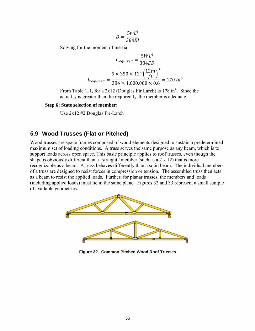
Wood trusses are space frames composed of wood elements designed to sustain a predetermined maximum set of loading conditions. A truss serves the same purpose as any beam, which is to support loads across open space. This basic principle applies to roof trusses, even though the shape is obviously different than a ―straight‖ member (such as a 2 x 12) that is more recognizable as a beam. A truss behaves differently than a solid beam. The individual members of a truss are designed to resist forces in compression or tension. The assembled truss then acts as a beam to resist the applied loads. Further, for planar trusses, the members and loads (including applied loads) must lie in the same plane. Figures 32 and 33 represent a small sample of available geometries.
Figure 32. Common Pitched Wood Roof Trusses
56
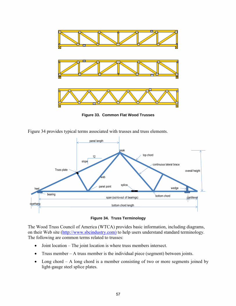
Figure 33. Common Flat Wood Trusses
Figure 34 provides typical terms associated with trusses and truss elements.
Figure 34. Truss Terminology
The Wood Truss Council of America (WTCA) provides basic information, including diagrams, on their Web site (http://www.sbcindustry.com) to help users understand standard terminology. The following are common terms related to trusses:
Joint location – The joint location is where truss members intersect.
Truss member – A truss member is the individual piece (segment) between joints.
Long chord – A long chord is a member consisting of two or more segments joined by light-gauge steel splice plates.
Bottom chord – A bottom chord is one or more members that form the bottom of the truss. Bottom chord members are most often horizontal, but for some applications, such as a ―cathedral-type‖ ceiling, they may be sloped.
Top chord – A top chord is one or more members that form the top of the truss, which also forms the roof surface. Top chord members are most often sloped. For the simple gable (―A‖) roof, there will be one line of top chord members for each roof slope.
Web – A web is a member between the bottom chord and top chord. A web member is almost always vertical or sloped.
Connection plate – A connection plate is light-gauge steel plate used to connect the various wood members. Plates are installed at the factory, as it is not practical to install the standard connection plates at the site.
Panel point – A panel point is a connection location of a web member to a top or bottom chord (but does not include splices).
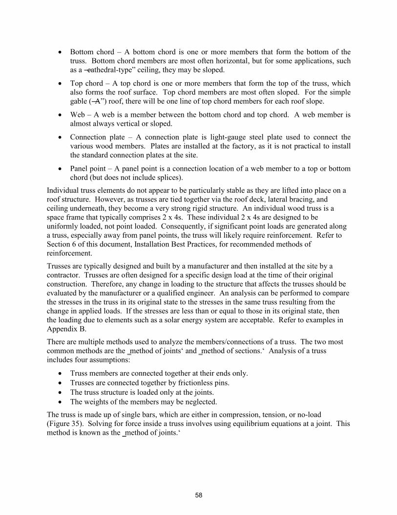
Individual truss elements do not appear to be particularly stable as they are lifted into place on a roof structure. However, as trusses are tied together via the roof deck, lateral bracing, and ceiling underneath, they become a very strong rigid structure. An individual wood truss is a space frame that typically comprises 2 x 4s. These individual 2 x 4s are designed to be uniformly loaded, not point loaded. Consequently, if significant point loads are generated along a truss, especially away from panel points, the truss will likely require reinforcement. Refer to Section 6 of this document, Installation Best Practices, for recommended methods of reinforcement.
Trusses are typically designed and built by a manufacturer and then installed at the site by a contractor. Trusses are often designed for a specific design load at the time of their original construction. Therefore, any change in loading to the structure that affects the trusses should be evaluated by the manufacturer or a qualified engineer. An analysis can be performed to compare the stresses in the truss in its original state to the stresses in the same truss resulting from the change in applied loads. If the stresses are less than or equal to those in its original state, then the loading due to elements such as a solar energy system are acceptable. Refer to examples in Appendix B.
There are multiple methods used to analyze the members/connections of a truss. The two most common methods are the ‗method of joints‘ and ‗method of sections.‘ Analysis of a truss includes four assumptions:
Truss members are connected together at their ends only. Trusses are connected together by frictionless pins. The truss structure is loaded only at the joints. The weights of the members may be neglected.
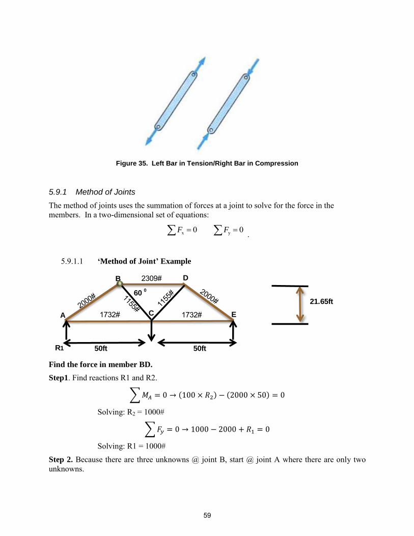
The truss is made up of single bars, which are either in compression, tension, or no-load (Figure 35). Solving for force inside a truss involves using equilibrium equations at a joint. This method is known as the ‗method of joints.‘
58
Figure 35. Left Bar in Tension/Right Bar in Compression
5.9.1 Method of Joints
The method of joints uses the summation of forces at a joint to solve for the force in the members. In a two-dimensional set of equations:
.
‘Method of Joint’ Example 5.9.1.1
Find the force in member BD. Step1. Find reactions R1 and R2.
∑ ( ) ( )
Solving: R2 = 1000#
∑
Solving: R1 = 1000#
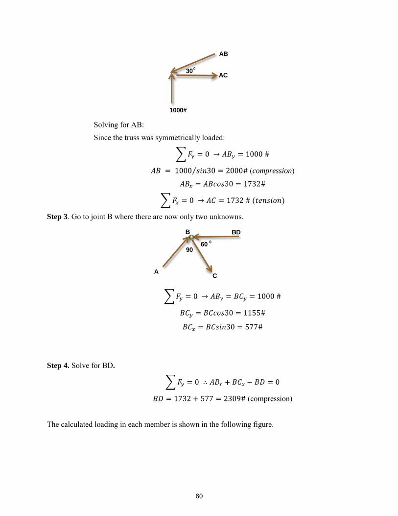
Step 2. Because there are three unknowns @ joint B, start @ joint A where there are only two unknowns.
x y0 0 F F= =
B
50ft
D
A C E
600
50ft
21.65ft
R1
2309#
1732# 1732#
59
Solving for AB: Since the truss was symmetrically loaded:
∑
⁄ (compression)
∑ ( )
Step 3. Go to joint B where there are now only two unknowns.
∑
Step 4. Solve for BD.
∑
(compression)
The calculated loading in each member is shown in the following figure.
1000#
AB
AC30
0
BDB
600
90
CA
60
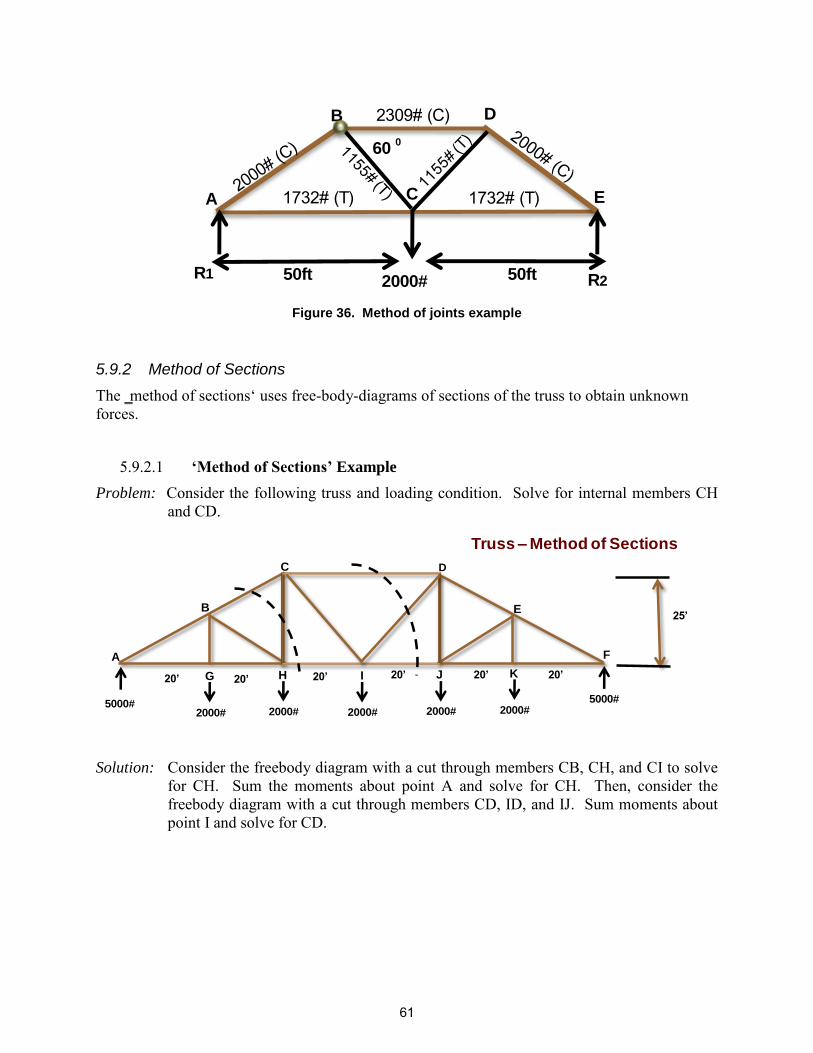
Figure 36. Method of joints example
5.9.2 Method of Sections
The ‗method of sections‘ uses free-body-diagrams of sections of the truss to obtain unknown forces.
‘Method of Sections’ Example 5.9.2.1Problem: Consider the following truss and loading condition. Solve for internal members CH
and CD.
Solution: Consider the freebody diagram with a cut through members CB, CH, and CI to solve for CH. Sum the moments about point A and solve for CH. Then, consider the freebody diagram with a cut through members CD, ID, and IJ. Sum moments about point I and solve for CD.
B
50ft 2000#
D
A C E
600
50ft R2R1
2309# (C)
1732# (T) 1732# (T)
5000#2000# 2000#
5000#
20’ 20’ 20’ 20’ 20’ 20’
A
B
C D
E
F
Truss – Method of Sections
G H
2000#
I
2000#
J
2000#
K
25’
61
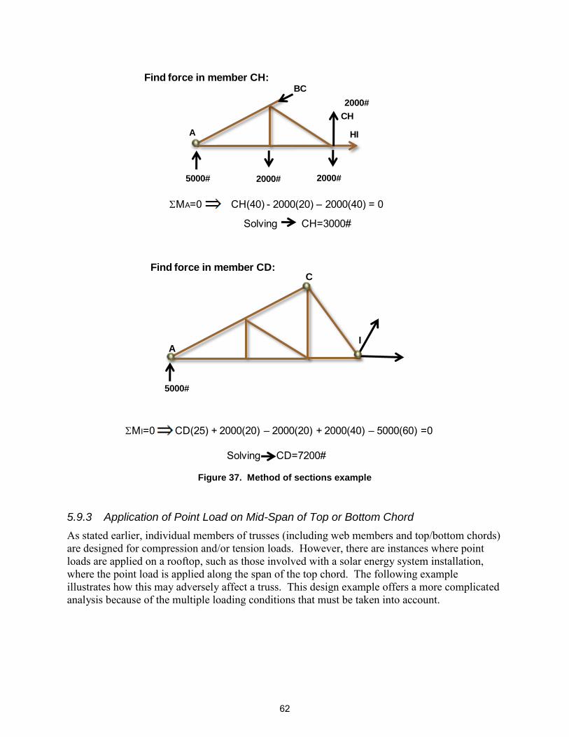
Figure 37. Method of sections example
5.9.3 Application of Point Load on Mid-Span of Top or Bottom Chord
As stated earlier, individual members of trusses (including web members and top/bottom chords) are designed for compression and/or tension loads. However, there are instances where point loads are applied on a rooftop, such as those involved with a solar energy system installation, where the point load is applied along the span of the top chord. The following example illustrates how this may adversely affect a truss. This design example offers a more complicated analysis because of the multiple loading conditions that must be taken into account.
Problem: Consider an 8-ft-long 2 x 6 with lateral cross bracing at 4 feet as shown above. The member is loaded with a 200-pound vertical load with a 2800-pound compression load. The top chord of the truss is select 2 x 6 Douglas Fir-Larch.
Solution: The following are the design values and applicable factors obtained from appropriate references, such as NDS.
Fb = 1500 psi E = 1.9 x 10⁶ psi S = 7.56 in3 Fc = 1700 psi
Cd = 1 Ct = 1 Ci = 1 Cr = 1 Cm = 0.9
Cm = 1.7 x 10⁶ psi
Lu = 4 ft ( ) Le = 1.11 Lu = 1.11*4*12 = 52.8 in
Slenderness ratio (NDS section 3.33)
RB = √
= √ ( )
( ) = 11.36 ˂50
Therefore satisfies criteria of NDS section 3.33
KbE = 0.439 (Euler buckling coefficient per NDS section 3.3.3)
Critical Buckling:
FbE =
( )
= 5783 psi
Bending:
Use Cm = 0.85 (wet service factor per NDS Support Table 4A).
Use Cf = 1.3 (size factor for flexure per NDS Support Table 4A)
Fb* = FbCmCf = 1500(0.85)(1.3) = 1657 psi
FbE FbE
Fb* =
= 3.49
63
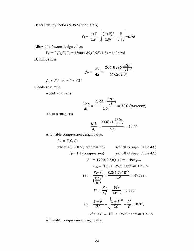
Beam stability factor (NDS Section 3.3.3)
√
( )
Allowable flexure design value:
Fb‘ = FbCmCLCF = 1500(0.85)(0.98)(1.3) = 1626 psi
Bending stress:
( )(
)
( )
therefore OK
Slenderness ratio:
About weak axis
( )(
)
( )
About strong axis
( )(
)
Allowable compression design value:
where: Cm = 0.8 (compression) {ref. NDS Supp. Table 4A}
CF = 1.1 (compression) {ref. NDS Supp. Table 4A}
( )( )
(
)
( )
√
Allowable compression design value:
64
( )( )( )
Actual compression stress:
Critical Euler buckling design value in plane bending:
(
)
( )
( )
Moment magnification factor for axial compression and bending
Apply Interaction Equation (compression and bending)
(
) (
)
( )
This example was provided to show that the addition of what appears to be a relatively small vertical point load of 200 pounds (which could be a single leg of a solar energy system installation) at the mid-span of the top chord of a roof truss can overload that truss. As stated earlier, all truss members are designed to take loads in tension and compression only. Therefore, it is recommended that point loads applied as a result of solar energy system installation be reinforced accordingly. Refer to Section 6 of this document, Installation Best Practices, for recommended reinforcement methods.
The following is an Excel program that allows the solar installer to calculate loads on structural members, given the input variables outlined. The software package is referred to as Solarstruc Version 2.0. For a copy of the software, contact Alan Harper or Kay Schindel with the City of Madison, Wisconsin (www.cityofmadison.com).
65
66
Figure 39. Example Solarstruc Output
67
5.10 Single-Member Structural Steel Beams or Joists (Flat or Pitched)
This document is intended to cover structural issues related to small buildings, predominantly residential. Although wood is the typical construction material for these structures, there are a few that utilize other materials, such as steel. The difference in materials is due to periods in which wood prices spiked and a significant number of structures were built using steel instead of wood. (The last instance occurred during the early 1990s.)
Two types of structural steel exist in building construction—hot rolled steel shapes and cold-formed steel shapes.
Hot rolled steel shapes are formed at elevated temperatures while cold-formed steel shapes are formed at room temperature. Hot rolled steel follows guidelines set forth by the American Institute of Steel Construction (AISC) in the Manual of Steel Construction, which provides design standards and property values.
Cold-formed steel structural members are shapes commonly manufactured from steel plate, sheet metal, or strip material. The manufacturing process involves forming the material by either press-braking or cold roll-forming to achieve the desired shape. Cold-formed steel follows the design standards set forth in the Specification for the Design of Light Gage Steel Structural Members published by the American Iron and Steel Institute (AISI).
When steel is formed by press-braking or cold roll-forming, there is a change in the mechanical properties of the material by virtue of the cold working of the metal. When steel sections are cold-formed from flat sheet or strip, the yield strength—and to a lesser extent the ultimate strength—increases. This is particularly true in the bends of the section.
In building construction, cold-formed steel products can be classified into three categories: members, panels, and prefabricated assemblies. The material thicknesses for such thin-walled steel members usually range from 0.0147 inches (0.373 mm) to about 0.25 inches (6.35 mm). Steel plates and bars as thick as 1 inch (25.4 mm) can also be cold-formed successfully into structural shapes. Typical cold-formed steel members such as studs, track, purlins, girts, and angles are mainly used for carrying loads while panels and decks constitute useful surfaces such as floors, roofs and walls, in addition to resisting the in-plane and out-of-plane surface loads. Prefabricated cold-formed steel assemblies include roof trusses, panelized walls or floors, and other structural assemblies. Approximately 40% of the total steel used in building construction is cold-formed steel.
The methods used to calculate applied stresses are similar to that presented in the previous section and in the design examples in Appendix B. Calculation of allowable stresses for steel is more straightforward than that for wood, as steel does not require the modification factors that apply to wood. Allowable stresses and section properties can be obtained from AISC or AISI design manuals.
The strength and stability of any structure depends heavily on the fastenings that hold its parts together. Consistent with the majority of this document, this section will concentrate on connections involving wood members. One prime advantage of wood as a structural material is the ease with which wood structural parts can be joined together with a wide variety of fastenings—nails, spikes, screws, bolts, lag screws, drift pins, staples, and metal connectors of various types. For utmost rigidity, strength, and service, each type of fastening requires joint designs adapted to the strength properties of wood along and across the grain and to dimensional changes that may occur with changes in moisture content. Design requirements for most mechanical fasteners are specified in the NDS for Wood Construction (AF&PA, 2005).
Mechanical connections are constructed using two general fastener types—dowels and bearings. Dowel-type fasteners, such as nails, screws, and bolts, transmit either lateral or withdrawal loads. Lateral loads are transmitted by bearing stresses developed between the fastener and the members of the connection. Withdrawal loads are axial loads parallel to the fastener axis, transmitted through friction or bearing to the connected materials. Metal connector plates are a special case of dowel-type fasteners; they combine the lateral load actions of dowel fasteners and the strength properties of the metal plates. Bearing-type connections transmit lateral loads only.
Bearing-type fasteners, such as shear plates and split ring connectors, transmit shear forces through bearing on the connected materials. Hanger-type connections are a combination of dowel and bearing-type fasteners. They generally support one structural member and are connected to another member by a combination of dowel and bearing action. Selection of a fastener for a specific design application depends on the type of connection and the required strength capacity. Each connection must be designed to transmit forces adequately and provide satisfactory performance for the life of the structure without causing splitting, cracking, or excessive deformation of the wood members.
The strength of mechanical fasteners is dependent on many factors, including the following:
1. Lumber species (density or specific gravity) 2. Critical section 3. Angle of load to grain 4. Spacing of mechanical fasteners 5. Edge and end distances 6. Conditions of loading 7. Eccentricity 8. Modification to tabular design values
6.1 Nails, Spikes, and Staples
Nails are the most common type of mechanical fasteners used in construction. Nails resist either lateral or withdrawal forces or a combination of the two. There are many variations in types of nails as well as shapes, treatments, coatings, finishes, sizes, and qualities.
Withdrawal resistance of a nail shank from a piece of wood depends on material density, nail diameter, penetration depth, and surface condition of the nail. For bright, common wire nails
69
driven into the side grain of dry wood or green wood that remains wet, many test results have shown that the maximum withdrawal load is given by the empirical equation:
⁄ Where: pw = maximum load,
L = the depth (mm) of penetration of the nail in the member holding the nail point,
G = the specific gravity of the wood based on oven dry weight and volume at 12% moisture content, and
D = the nail diameter (mm).
Figure 40. Typical Nail Sizes/Gage
Spikes are long, nail-like fasteners designed to connect larger-sized elements. Staples are made of thin wire and consist of two legs and a crown. Staples have a variety of sizes, points, coatings, and quality. They are available in clips and coils to permit use in pneumatically operated staplers. Staples are also used in low-strength or nonstructural connections and resist lateral and withdrawal forces. A typical fastening schedule of wood members with nails is included in IRC 2009, Table R602.3(1).
The following example estimates the pullout strength of a toe-nailed connection.
Example:
Problem: Determine the lateral design value for a 3-inch-long 10d common wire nail in a toe-nailed connection shown below. The wood is Douglas Fir-Larch.
70
Solution:
( )
Nominal design value for single shear per NDS Table 11N: Z = 118#
Assume the following modification factors: Cm = 1.0, Ct = 1.0, CD = 1.6
Nail penetration: ( )
This penetration depth is greater than the minimum recommended (P = 10 dia. per NDS Table 11N),
Therefore, Cd = penetration depth factor = 1.0
Ctn = toe-nail factor = 0.83 (NDS Sect. 11.5.4)
Allowable Lateral Design Value:
Although toe-nailing wood members is a common method of attachment, there are many metal connectors commercially available that offer significantly stronger connection strength. An example is shown in Figure 41.
Lag screws are threaded fasteners with a square or hex head that are placed in wood members by turning with a wrench. Although lag screws have a lower lateral strength than comparable bolts, lag screws are advantageous when an excessive bolt length is required or when access to one side of a connection is restricted. Wood screws are usually made of steel or brass and are classified according to material, type, finish, head shape, and shank diameter. Both lag and wood screws provide lateral and withdrawal resistance.
72
Figure 42. Lag Screw Connection
Both wood screws and tapping screws are used in wood construction and are available in a wide range of materials and head types. The maximum withdrawal load (pq) for wood screws inserted in the side grain of seasoned wood may be expressed as:
Where: D = the screw shank diameter (mm) G = the specific gravity of the wood based on oven dry weight and
volume at 12% moisture content L = penetration length (mm) of the threaded part of the screw
This equation is applicable for screw lead holes with a diameter of about 70% of the root diameter of the threads in softwoods, and about 90% in hardwoods. Withdrawal resistance of tapping screws is generally 10% greater when compared with wood screws of similar diameter and threaded length. Lateral screw strength is determined by single shear yield theory expressions similar to that for nail design.
Maximum withdrawal load (pr) for lag screws from seasoned wood is given by:
⁄
⁄
73
Lag screws require lead holes that vary from about 40% to 85% of the root diameter, depending on the wood density.
Table 10 presents an example of pull-out strength values for a variety of woods for a 5/16-in diameter shaft lag screw (Source: American Wood Council, NDS 2005, Table 11.2A, 11.3.2.).
Table 10. Pull-Out Strength for Lag Screws
Table Notes: (1) Thread must be embedded in the side grain of a rafter or other structural member integral with the building structure. (2) Lag bolts must be located in the middle third of the structural member. (3) These values are not valid for wet service. (4) This table does not include shear capacities. If necessary, contact a local engineer to specify lag bolt size with regard to shear
forces. (5) Install lag bolts with head and washer flush to surface (no gap). Do not over-torque. (6) Withdrawal design values for lag screw connections shall be multiplied by applicable adjustment factors if necessary. See Table
10.3.1 in the American Wood Council NDS for Wood Construction. *Use flat washers with lag screws. Flat washers are not necessary with concealed screws.
The Industrial Fastener Institute (Inch Fastener Standards, 7th ed. 2003. B-8) states that shear strength is approximately 60% of the minimum tensile strength.
“As an empirical guide, shear strengths of carbon steel fasteners may be assumed to
be approximately 60 percent of their specified minimum tensile strengths. For
example, an SAE grade 5 hex cap screw has a specified minimum tensile strength of
120,000 psi. Therefore, for design purposes, its shear strength could be reasonably
assumed to be 70,000 psi.”
6.3 Bolts, Drift Bolts, and Pins
Bolts are the most common wood fastener for connections where moderately high lateral strength is required. They are also used in tension connections where forces are applied parallel to the bolt axis. The bolts used for structural connections are standard machine bolts. Drift bolts and drift pins are long unthreaded bolts, steel pins, or steel dowels that are driven in pre-drilled
Lag pull-out (withdrawal) capacities for 5/16-in dia. Shaft*
Wood Type Specific gravity Capacity per inch thread
depth (lbs)
Douglas Fir, Larch 0.5 266
Douglas Fir, South 0.46 235 Engelmann Spruce, Lodgepole Pine (MSR 1650f
& higher) 0.46 235
Hem, Fir, Redwood (close grain) 0.43 212
Hem, Fir (North) 0.46 235
Southern Pine 0.55 307
Spruce, Pine, Fir 0.42 205
Spruce, Pine, Fir (E of 2 million psi and higher
Thread depth grades of MSR and MEL) 0.5 266
74
holes. Drift bolts include a head on one end, while no head is provided on pins. Drift bolts and pins are used in lateral connections for large wood members. They are not suitable for withdrawal connections because of their low resistance to withdrawal forces.
The yield theory approach is used to determine the lateral strength of single-bolted connections, assuming sufficient edge and end distances. Edge and end distances ensure that the wood will not split or tear and will only fail in bearing.
6.4 Metal Connector Plates
Metal connector plates—commonly called metal plate connectors, steel truss plates, truss plates, or plates—are used extensively in wood trusses. These plates are proprietary products, but are generally made of light-gauge structural-quality steel with zinc or zinc-aluminum alloy coatings or stainless steel metal connector plate with integral teeth; they are manufactured to various lengths, widths, and thicknesses. Plates are designed to transmit lateral loads; however, some moment is transferred in a truss as a result of change in geometry as it deflects.
6.5 Fastener Spacing and Edge Distances
Spacing of mechanical fasteners is the distance between centers of the fasteners measured on a straight line joining their centers. Edge distance is the distance from the edge of a member to the center of the mechanical fastener closest to that edge, measured perpendicular to the edge. End distance is the distance, measured parallel to grain, from the center of a mechanical fastener to the square-cut end of a member. Figures 43 to 46 are illustrations from the AWC (http://www.awc.org/index.html):
Figure 43. Fastener Spacing (1)
75
Figure 44. Fastener Spacing (2)
Figure 45. Fastener Spacing (3)
76
Figure 46. Fastener Spacing (4)
Tables 11 and 12 offer minimum guidance for full-strength development of wood fasteners.
Table 11. End Distance Requirements
End Distance Requirements
Direction of loading Minimum End
Distance
Perpendicular to the Grain 4 X dia.
Parallel to the Grain, Compression: (fasteners bearing away from the member end)
4 X dia.
Parallel to Grain, tension (fastener bearing toward member end) for Softwoods 7 X dia.
for Hardwoods 5 X dia.
Table 12. Spacing Requirements
Spacing Requirements for Fasteners in a Row
Direction of Loading Minimum End Distance
Perpendicular to the Grain Required spacing for attached members
Parallel to the Grain 4 X dia.
77
6.6 Wood Connection Design Considerations
The strength of wood connections is often limited by the resistance of the wood in bearing or withdrawal rather than by the strength of the fastener. As a result, connection design is affected by many of the same factors that influence the strength properties of wood. In addition to the type, number, and size of fasteners, connection strength also depends on such factors as the wood species, direction and duration of load, and conditions of use. In some cases, the strength of the connection may also be limited by the capacity of the connected members. Design values for different types of nonproprietary fasteners are given in building codes and specifications in either tabular or equation format. These values are based on one fastener, installed and used under specified conditions. Allowable design loads are determined by adjusting tabulated or calculated values with adjustment factors. When more than one fastener is used in a connection, the design value is the sum of the design values for the individual fasteners times any applicable adjustment factor.
It should be noted that design criteria and tabulated loads are limited to connections involving the same type of fastener. A simplified connection calculator is offered by the AWC at http://www.awc.org/calculators/connections/ccstyle.asp. This online calculator provides users with a web-based approach to calculating capacities for single bolts, nails, lag screws, and wood screws per the 2005 NDS. Both lateral (single and double shear) and withdrawal capacities can be determined. Wood-to-wood, wood-to-concrete, and wood-to-steel connections are possible.
The basic design procedures for connections are similar to those for structural components. For a given connection and type of fastener, the designer must:
1. Determine the tabulated load for one fastener appropriate for the connection of the structural members.
2. Apply adjustment factors to the tabulated value to reflect specific applications and conditions of use.
3. For connections to wood members, adjust the modified value for lateral loading conditions other than parallel or perpendicular to grain, when applicable.
4. Multiply the design load for one fastener by the total number of fasteners in the connection and apply a group adjustment factor if justified.
5. Compute the net section properties and verify the capacity of the members. 6. Detail the connection to ensure adequate fastener placement and performance.
Best practices for the installation of a solar energy system involve the optimization of the system for solar energy production as well as structural considerations. Elements to be optimized in a solar energy system include:
Roof orientation with respect to panel orientation – sun path chart and shade ellipse Roof slope – the type of solar mount installation and associated safety issues Shading – solar panel placement with respect to shading from chimneys, vents, trees, etc. Setback requirements – determined by local building codes; can be an issue with regard
to installer/maintenance issues Type of roof – includes shape (flat or sloped) and material (asphaltic shingle, shake, clay
tile, metal, etc.); will dictate placement and connections Structural roof framing details – wood rafter, wood truss, wood beams with steel bar
joists, and structural steel are multiple structural options that will impact best installation practices
Panel array layout – panel layout (portrait or landscape) and number of panels will impact the best installation practices
7.1 Setback Requirements
Setback requirements for roof structures will impact the location within the roof boundary where the solar energy system can be placed. There are several critical considerations for solar energy systems with respect to setback requirements including safety, local building codes, accessibility during an emergency, and pressure from wind loading,
Safety is of utmost importance for installers and for the maintenance of solar energy systems. Safety concerns dictate a safe setback distance for personnel installing and maintaining the systems. Further, many local building codes may include setback requirements; the authority having jurisdiction should be consulted to verify whether they have such requirements and, if so, what those requirements are. Another consideration for setback distances is sufficient room for emergency personnel, such as firefighters. Firefighters must be able to access the roof and require adequate space for making smoke venting openings at the high point of the roof.
Other considerations for setback involve pressure from wind loading. The highest wind loads on roof structures are around the perimeter of the roof and along the eaves. To avoid the highest wind pressure areas, it is recommended that minimum setbacks from the roof eave/ridge be three feet. In heavy snow regions, the standoff distance should be greater than three feet.
7.2 Locating Roof Structural Members
Any significant weight placed on a roof should be optimally placed based on the location of the roof structural members, and the integrity of the structure should be evaluated to verify that is adequate to handle the additional stresses.
If attic access is available, it can be utilized to locate the rafters or trusses. From inside the attic, using a rafter or truss at one end of the roof, each rafter/truss can be measured and mapped for the remainder of the roof. To locate a specific rafter/truss, the installer can drill two small holes adjacent to the rafter/truss spaced approximately 10 feet along the rafter/truss. Then, from the
79
rooftop, the exact location and direction can be identified and measured to other structural elements as needed. These holes must be patched when the job is complete or prior to inclement weather.
If an attic does not exist or is inaccessible, other techniques can be used to locate structural elements, including using stud finders, nailing patterns along the soffit or fascia, or even by simply tapping on the roof with a hammer or rubber mallet. Drilling small test holes from the rooftop and using an item such as a thin wire to locate the structural element can also be used. If a pilot hole is drilled on a shingled roof, it should be placed by lifting the leading edge of a shingle and drilling beneath it. This way, the shingle can replaced over the hole to seal it. Whichever method is used to locate rafters and drilling pilot holes, all pilot holes must be sealed; the sealant used must be compatible with the roofing material.
7.3 Structural Attachment to Roof
It is highly recommended that anything attached into the roof by a screw, nail, or bolt not be directly attached to the roof rafter or top chord of a truss. This can damage or split the structural member and reduce its load-carrying capacity. Rather, it is recommended that a structural member span between two rafters or trusses; the attachment from the roof would attach into this spanned member. For example, place a 4 x 4 cross beam between two rafters or trusses (see Figure 47) and attach this member to the rafters or trusses with hangers. Then attach through the roof to this new cross beam. The method shown below is approved as an acceptable method for supporting a solar installation on a trussed roof. The following is suggested criteria for this system.
1. The truss spacing should not exceed 24 inches on center. 2. A minimum cross-sectional member of 4 x 4 lumber should be used as a brace between
trusses. 3. The brace is within 12 inches of a panel point on the top chord of the truss. 4. The support legs for the solar installation are lag or thru-bolted to the brace. 5. The brace is attached to the trusses with mechanical fasteners (hangers) sized to carry the
required uplift and down loads.
80
Figure 47. Cross Beam for Solar Attachment
Figure 47 notes:
a. A panel point is where the webs meet the chord. There is a truss plate at this location and it is the best location to install the brace. The hangers can be nailed through the truss plates.
b. Several manufacturers make face-mount hangers that are suitable for this installation. Hangers
similar to the one shown in the diagram have a capacity of approximately 280 pounds each. If two are installed at each end, this gives a capacity of 1,120 pounds for this support.
Another effective method involves scabbing a 2 x 2 to the side of a roof rafter or top chord of a truss. This additional 2 x 2 member must be physically attached to the rafter or truss, then attached through the roof to the scabbed member. If placement of a cross beam or scabbing a 2 x 2 to an existing rafter or truss is not practical, and attachment through the roof to the rafter or truss is required, then the attachment point must be within the center third of the rafter or top chord of the truss (see Figure 48). This will reduce the possibility of splitting the wood member or reducing its structural capacity. General rules for installation of mechanical fasteners into a wood member includes maintaining a minimum edge distance of 1.5 times the diameter (1.5 x D) of the mechanical fasteners with a minimum end distance of 4 times the diameter (4 x D) of the mechanical fastener. A 0.5-inch diameter lag bolt must be in the exact center of a 2 x 2 member and perfectly aligned to meet the requirement of having the fastener in the middle third of the member.
81
Figure 48. Centered attachment
7.4 Weatherproof Attachment of Solar Energy System to Roof
An American Society for Testing and Materials (ASTM) International (ASTM) standard is currently under development to address the installation of roof-mounted photovoltaic arrays to assist with guidance for properly weatherproofing roof penetrations. This standard was not complete at the time of publication of this document. The work item is currently referred to as ASTM WK21327 - New Practice for the Installation of Roof Mounted Photovoltaic Arrays. The scope of this standard to date is:
1.1 This Standard Practice details minimum requirements for the mechanical installation of roof-mounted PV (not building-integrated PV) arrays in residential or commercial applications. These requirements include proper water-shedding integration with the existing roof system, water sealing of roof penetrations, and sufficient anchoring per regional pressure load requirements.
1.2 Installation considerations are divided into two distinct aspects—the interface between the PV module and the roof framing system and the interface between the roof framing system and the roof.
1.3 Safety/hazard considerations, such as worker fall protection on high-pitched roofs, electrical exposure, accessibility of modules, and roof clearance around the perimeter of the array are also addressed. This practice is not intended to replace or supersede any other applicable requirements for a given installation. Because of the rapid growth in the PV market, there are many new installers who do not have experience and could benefit from guidelines on best practices for both residential and commercial applications.
The National Roofing Construction Association (NRCA) has multiple recommendations for roof systems related to the installation of a solar energy system. Unsurprisingly, this includes recommending a new roof. More unbiased guidelines, however, include the following:
The remaining life of the roof system should be equivalent to the useful service life of the solar energy system.
The installation of a PV system on the roof will accelerate the aging of the roof system near the array.
82
Penetrations should be minimized, as they lead to roof leaks and roof degradation. Additional foot traffic associated with solar installation and maintenance will accelerate
degradation of roof systems.
Based on these guidelines, the NRCA recommends that a new roof system installed with the intent of having a solar rooftop system should include three key components—high-compressive strength rigid board insulation if the insulation is on the surface of the roof structure rather than beneath it; a thermal barrier directly beneath a roof membrane; and a roof membrane designed with an increased puncture resistance/thickness.
Primary guidelines for various roof types include the following:
7.4.1 Composition Roof
Composition roofs are also known as asphaltic tile roofs; these are flexible and compressible. Anchors can be standoff mounts and clip angles.
A. Rafters can be located using a stud finder or other non-destructive method.
B. Attachment through the shingle itself can be done, but a more effective method is to cut away the shingle at the anchor location and flash with asphaltic mast.
C. Aluminum/stainless steel angles are securely attached to the underlying rafter scab or cross member with stainless steel lag screws. This assembly is then sealed using a urethane caulking material.
General Mounting Practices
Pre-drill before installing lag screw.
Apply sealant in hole and apply a small amount to the upper threads of lag screw.
Set clip angle or standoff in approved mastic sealant.
Apply flashing around clip angles and standoffs. Set flashing in mastic bed.
7.4.2 Wood Shake Roof
Wood shakes can crack and leak if they are drilled or compressed. Therefore it is best to remove several shakes to locate the underlying rafters. Metal standoffs can then be installed to these rafters with stainless steel lag screws, and the standoffs can be sealed and flashed using a urethane caulking material. Shakes are then replaced around the standoffs.
7.4.3 Masonry or Rigid Tile Roof
Masonry shakes can crack and leak if they are drilled or compressed. Therefore, several shingles must be removed to locate the underlying rafters. Metal standoffs can then be installed to the rafter scabs or cross members with stainless steel lag screws, and the standoffs can be sealed and flashed using a urethane caulking material. Shingles are replaced around the standoffs.
7.4.4 Flat Roof
Since water can pool on flat roofs, it is particularly important that a flat roof be in good condition before installation. For these installations, aluminum angles can be securely attached to the underlying rafter scabs or cross members with stainless steel lag screws. This assembly is then
83
sealed using a durable caulking material. If there is any possibility of water pooling around the roof attachments, it may be necessary to anchor the attachment points to wooden or metal ―sleepers,‖ which are mounted above the roof surface.
Figure 49 shows examples of commercial products available to assist with roof-mounted installations.
Figure 49. Example of Flat Roof Mounts
Examples of Sharp‘s Solar Racking System (SRS) are shown in Figures 50 and 51.
84
Figure 50. Asphalt Shingle Roof
Figure 51. Flat-tile Roof
Figure 52. High-profile Tile Roof
7.5 Recommended Methods for Reinforcing Overstressed Rafters
Many homes were built with roof rafters or trusses that were designed with no excess margin in them. In fact, some homes were not designed for the stresses to which they are currently exposed. This section provides possible recommendations that can be used by installers when installing a solar energy system on a rooftop. Site-specific requirements of each respective project will dictate which (if any) of the examples is appropriate.
Figure 53 is a simple diagram of a sloped roof that comprises rafters, with the designated rafter that could be overstressed due to the additional weight of a solar energy system installation.
85
Figure 53. Section of House Structure
7.5.1 Recommended Method 1
Use existing knee wall or add knee wall or vertical brace (Figure 54).
Design considerations:
1. Transfers load to ceiling joists (joists may not be able to carry the extra load). 2. May not cure the overstress (if allowable rafter span is still exceeded or a point
load is not over the brace).
Advantages:
1. Relatively simple.
Overstressed rafter
Ceiling joist
Interior bearing wall
Exterior bearing wall
86
Figure 54. Recommended Method 1, Vertical Brace
7.5.2 Recommended Method 2.
Brace rafter to interior bearing wall (Figures 55 and 56).
Design considerations:
1. The brace connection has very little capacity if tacked to the side of the rafter. A better design is to keep the brace in plane with the rafter and attach it with mechanical connectors.
2. The brace should be perpendicular to the rafter. 3. May not cure the overstress (if allowable rafter span is still exceeded or a point
load is not over the brace). 4. May not cut down unbraced span enough to be effective on low slope roofs.
Advantages:
1. Relatively simple.
2. Transfers load directly to a vertical support member.
Overstressed rafter
Ceiling joist
Interior bearing wall
Exterior bearing wall
ADDED WALL OR BRACE
87
Figure 55. Recommended Method 2, Added Brace(1)
Figure 56. Recommended Method 2, Detail for Added Brace
Overstressed rafter
Ceiling joist
Interior bearing wall
Exterior bearing wall
ADDED BRACE
CONNECTION DETAIL
ADDED BRACE
Overstressed rafter
Mechanical connector
88
7.5.3 Recommended Method 3
Sister new rafter to existing rafter (Figures 57 and 58). This method involves attaching a full length rafter of a similar cross section to the existing rafter, essentially doubling the cross-sectional area of the existing rafter.
Design considerations:
1. The rafters may be difficult to install.
2. The rafters must be fully supported at the ridge and wall. If the new rafter is deeper than the existing rafter, this may require a deeper ridge board than the existing ridge board and may not be possible at the wall due to lack of bearing area.
Advantages:
1. Supports loads for the entire length of the rafter so load placement above may not be so critical.
2. Can be used for flat roofs or sloped roofs without attics.
3. Leaves attic space clear of extra braces or beams.
Figure 57. Recommended Method 3, Sister Rafter
Overstressed rafter
Ceiling joist
Interior bearing wall
Exterior bearing wall
ADDED RAFTER
89
7.5.4 Recommended Method 4
Add scab to existing rafter (Figure 58). This method involves attaching a wood member (typically of similar cross section) to the affected length of existing rafter.
Design considerations:
1. Typically, the scab would cover the middle third of the rafter span. (This may be different if there is a large point load off-center.)
2. A fastener pattern must be calculated and specified to transfer the loads between the rafter and scab.
3. Not as strong as a full rafter.
Advantages:
1. Easier to install than full added rafters.
2. Less material used than with a full added rafter.
3. Can be used with flat or sloped roofs without attics.
4. Leaves attic space clear of extra braces or beams.
Add beam under rafters (Figure 59). This method involves adding a beam to support multiple rafters. The beam in turn must be supported at bearing walls or columns at each end of the beam or along the beam.
Design considerations:
1. The beam must extend to bearing points on each end. The bearing points must be continuous to the ground.
2. The beam must be laterally supported to prevent overturning.
3. The longer the span of the beam, the larger the beam will have to be.
4. Often requires cutting a hole in an endwall to slide the beam in.
Advantages:
1. Can be used with flat or sloped roofs without attics.
2. Fewer pieces to install than methods using braces, additional rafters, or scabs.
Figure 59. Recommended Method 5, Add Support Beam
Overstressed rafter
Ceiling joist
Interior bearing wall
Exterior bearing wall
ADDED BEAM/supported at ends
91
7.5.6 Recommended Method 6
Put the array on the ground (Figure 60). This method can be utilized when it has been determined that the roof of a structure may not be the best option and that the easiest and most economical option may include placing the solar array on a pole-mounted system on the ground adjacent to the home.
This may be the only practical option on homes with significantly undersized roof structures or hard-to-modify roof structures.
Figure 60. Recommended Method 6, Ground Mount
92
This page is intentionally blank.
93
REFERENCES 81. AISC 2005. ASD/LRFD Steel Construction Manual, 13th Edition. American Institute of
Steel Construction, Chicago, IL. 2. AITC 1985. Timber Construction manual. American Institute of Timber Construction.
John Wiley & Sons, Hoboken, NJ. 3. ANSI/AF&PA NDS-2005. National Design Specification (NDS) for Wood Construction
with Commentary. American Wood Council. 4. ASCE 7-05. Minimum Design Loads for Buildings and Other Structures. American
Society of Civil Engineers. 5. BCSI 1-03. 2003. Guide to Good Practice For Handling, Installation & Bracing Of
Metal Plate Connected Wood Trusses. Jointly published by Wood Truss Council of America and Truss Plate Institute.
6. Denise, Garet. 2007. Inspecting Wood Trusses. ASHI [American Society of Home Inspectors] Reporter. http://www.ashireporter.org/articles/articles.aspx?id=1213
7. IBC 2009. International Building Code. International Code Council. 8. IFI, Industrial Fasteners Institute (2003). Inch Fastener Standards (7th ed.). Industrial
Fasteners Institute: Industrial Fasteners Institute. 9. IRC 2009. International Residential Code for One- and Two-Family Dwellings.
International Code Council. 10. NEC 2011. National Electric Code 11. SPAN TABLES FOR JOISTS AND RAFTERS. 2005. American Softwood Lumber
Standard (PS 20-05) Sizes. American Forest and Paper Association. American Wood Council, Washington DC.
12. Specification for the Design of Light Gage Steel Structural Members. American Iron and Steel Institute (AISI)
13. Truss Plate Institute (TPI) publication QST-88, Quality Standard For Metal Plate Connected Wood Trusses.
14. Wisconsin Uniform Dwelling Code. Wisconsin Department of Commerce.
Submitted by: Date Received: Address of Installation:
Reviewer: Reviewer Comments:
97
The following information is recommended to be included with the submittal form (other useful information is also encouraged):
Brief explanation of project Photos of the subject property: from public rights of way showing building; where
panels are to be located, and setting of building on property; interferences from vegetation other structures; a Google satellite image may be useful.
Roof structure/system description drawing/sketch of roof structure with horizontal dimensions from ridge to eave
lines, roof slopes indicated on plan, location of bearing walls, locate large openings such as sky lights,
framing system including direction of rafters/trusses, rafter dimensions with spacing and span, for trusses – top chord dimensions and truss sketch or specs
rafter/truss material (old or new lumber, size (top chord for truss), does it meet commercial grade #2 or better
roof decking system reinforcement to be added to support solar system (if applicable) condition of existing roof system (covering and structure), including any required
modifications: any rot, cracks, framing mistakes, etc. Solar project description w/ drawing(s)
what modules/collectors what rail/support system what type of mounting system useful description of connections provide mount data as available type of connection, how many fasteners, where…… any structural modifications
Load conditions total dead loads (roof system; solar system; rack system; other) snow load (e.g. 30psf in Wisconsin) wind load (exposure category B) for type of mount chosen (or seismic if
applicable) additional live loads (if applicable)
Documentation that structure is ‘adequate’ For systems that require no structural modifications or for systems with basic
“pre-approved” or other simple modifications:: Derivation of actual load to structural member(s) based on load conditions
specified above Derivation of allowable loads (may include calculations, use of tables,
manufacturer information, etc.) For systems requiring more complicated modifications, a full calculation package
from a qualified structural designer is needed Evidence the installation method will be sound (e.g. won’t split trusses, etc)
98
Brief summary of project: Insert Photos (add sheets as required):
99
Roof structure description:
Scale drawing of roof structure
100
Solar system description (manufacturer information, support, fasteners, etc):
Scale drawing of solar installation on rooftop and supporting drawings
Loads Associated with Solar System Installation Dead Load of permanent material: Roof material/insulation psf Roof sheathing psf Roof truss/rafter psf Solar panel psf Solar support system/rack psf Permanent material beneath truss/rafter supported by truss/rafter psf Other psf
101
Other psf TOTAL psf
Snow Load (list reference used: ASCE 7-05, local code, other):
Wind Load (list reference used: ASCE 7-05, local code, other):
Exposure B Method Used Wind Velocity mph Factors Factors
Wind Load psf
Live Load (if any) (list reference used: ASCE 7-05, local code, other):
Live Load psf Live Load
Live Load psf
102
CALCULATIONS (Roof structure, fastener adequacy. Include supporting documentation):
103
CALCULATIONS (cont.):
104
APPENDIX B: DESIGN EXAMPLES (SAC STRUCTURAL CONSIDERATIONS FOR SOLAR INSTALLERS IN WISCONSIN)
EXAMPLE #1
FLUSH MOUNTED SOLAR HOT WATER PANELS FLASHED INTO ROOFING.
NO RAILS. RAFTER ROOF STRUCTURE.
Through the process of load tabulation, determine whether a rafter roof can safely support a panel system that is flashed into the roofing and uniformly supported along its edges.
GIVEN INFORMATION:
1. 72" long x 54.1" (3 each) wide solar hot water panels in portrait weighing 141 pounds (5.22 pounds per square foot [psf] dead load) each when in service, including hardware.
2. Flashed into roofing without rails; thus, roofing is being removed below panels. 3. 2 x 8 grade 2 rafters of an unknown species spaced at 24 inches spanning 10' 9" with an
eight to twelve roof pitch covered with a light roofing material 4. Project located in Madison, Wisconsin, Zone 2, 30psf snow load, 20psf wind load
Figure B1. Cross Section
PROCEDURE:
1. Check compliance or rafters with current version of Uniform Dwelling Code (UDC) and the Wisconsin Administrative Code.
a. Tabulate dead loads. b. Check rafters against the UDC tables.
2. Tabulate new dead loads. (Snow loads and live loads do not need to be considered when the system is supported uniformly.)
105
3. Make comparison between design loading and proposed. a. Solar panel weight is added b. Roofing weight is added
CALCULATIONS:
1. Check compliance of rafters with current version of UDC. a. Tabulate dead loads.
3 Tab shingles and felt 2.2psf (one layer)
½" plywood 1.6psf
2 x 8 rafters at 24" 2.1psf
5.9psf total dead load ( )
Note: Design table calculations are based on horizontally projected loads on horizontally projected spans. Tabulated dead loads ( ) are calculated based on
the sloped surface and need to be converted to horizontally projected dead loads. This is done by multiplying the dead loads by the ratio of the sloped dimension to the horizontal dimension.
Figure B2. Relationship between Span and Slope
106
Figure B3. Plan View
Calculate horizontally projected dead loads ( ) for determining what UDC table to use:
⁄
⁄ ( )
( )
⁄ ( )
b. Check rafters against the UDC tables.
REFERENCE: UDC TABLES, SECTION 25 APPENDIX:
Zone 2 30 psf
Shingle (light) Roof 10psf
No Ceiling Attached to Rafter L/180 deflection requirement
USE TABLE R-14 30PSF LL 10PSF DL
2 x 8 @ 24" Span = 10'-9"
If the wood species is not known, the grading should be confirmed in the field as Grade 2 or better and a species of Spruce Pine Fir (SPF) assumed with a snow loading design value for bending, (Fb) = 1190 psi.
107
From Table R-14:
2 x 8 @ 24 inch centers with a fb=1100 psi can span 11'-0"; this is greater than 10'-9 American Society of Civil Engineer‘s and thus the existing roof rafters are OK.
2. Tabulate new dead loads. (Snow loads and live loads do not need to be considered when the system is supported uniformly without rails.)
Total Panel Dead Load Including Hardware
Horizontally Projected Plan Area Covered by Panels = ⁄
Distributed Uniform Dead Load
Make comparison between design loading and proposed.
Additional Panel Dead Load
Total Dead Load Including Panel, DL
Therefore OK because the resulting load at the panel is less than or equal to 10psf (+/- 10%) and the roof construction complies with the UDC, so the roof can be considered acceptable for supporting panel weights.
EXAMPLE #2
FLUSH MOUNTED SOLAR HOT WATER PANELS FLASHED INTO ROOFING.
NO RAILS. TRUSS ROOF STRUCTURE.
Through the process of load tabulation, determine whether a truss roof can safely support a panel system that is flashed into the roofing and uniformly supported along its edges.
GIVEN INFORMATION:
1. 72" long x 54.1" (3 each) wide solar hot water panels in portrait weighing 141 pounds (dead load) each when in service, including hardware.
2. Flashed into roofing without rails, thus roofing is being removed below panels. 3. Pre-manufactured wood trusses with the original truss design documentation stating
design loads of 10psf dead and 30psf live, spaced at 24 inches spanning 21' 6" with an eight to twelve roof pitch covered with a light roofing material.
4. Project located in Madison, Wisconsin, Zone 2: 30psf snow load, 20psf wind load
108
Figure B4. Cross Section
PROCEDURE:
2. Check compliance of existing roof trusses with current version of UDC and the Wisconsin Administrative Code.
a. Check truss design loads. 3. Tabulate new dead loads. (Snow loads and live loads do not need to be considered when
the system is supported uniformly.) 4. Make comparison between truss design loads and proposed loading.
CALCULATIONS:
1. Check compliance of existing roof trusses with current version of UDC.
From UDC
ZONE 2 Snow Load = 30 PSF
From Truss Design Documents
Snow Load = 30 psf
DLtop = 10 psf (Top Chord)
DLbot = 5 psf (Bottom Chord)
Tabulate Dead Loads:
3 Tab shingles and felt 2.2 psf (one layer)
½” plywood 1.6 psf
109
Wood Trusses NA Self weight of truss is considered in
the design of the 3.8 psf total dead load truss and not considered part of the top or bottom chord dead loads.
Wood truss design is based on horizontally projected loads on horizontally projected spans. Tabulated dead loads are calculated based on the sloped surface and need to be converted to horizontally projected dead loads. This is done by multiplying the dead loads by the ratio of the sloped dimension to the horizontal dimension.
Figure B5. Relationship between Span and Slope
Calculate horizontally projected dead loads, :
⁄
⁄ ( )
( ) Based on this information, existing roof trusses comply with the UDC. OK
2. Tabulate new dead loads. (Snow loads and live loads do not need to be considered when the system is supported uniformly without rails.)
Total Panel Dead Load Including Hardware
Horizontally Projected Plan Area Covered by Panels = ⁄
Distributed Uniform Dead Load
3. Make comparison between design loading and proposed.
110
Additional Panel Dead Load = 5.97 psf
Total Dead Load Including Panel, DL = 5.97 + 2.0 = 7.97 psf
7.97 psf < 10 psf . OK
Because the resulting load at the panel is less than 10psf and the roof construction complies with the UDC, the roof can be considered acceptable for supporting panel weights.
EXAMPLE #3
FLUSH MOUNTED SOLAR HOT WATER PANELS SUPPORTED BY RAILS. ON A
RAFTER ROOF STRUCTURE.
GIVEN INFORMATION:
1. 65" long x 40" (8 each) wide solar photovoltaic panels in two rows of 4. Panel weight equals 44 pounds (2.43 psf dead load, DL) each when in service. Rail weight equals 1 pound per linear foot (2.81 psf total equipment dead load).
2. System is supported on rails, attached at points along the roof, with rail reaction being obtained from the rail manufacturer’s web site. No rail reactions greater than 300 lb are calculated.
3. 2 x 8 Grade 2 rafters of an unknown species spaced at 24 inches spanning 10'-9" with an eight to twelve roof pitch covered with a light roofing material. All affected rafters have been visually inspected and are not cracked, split, or have any large knots.
4. Roofing material is considered light <10 psf, and the attic space below is not finished. 5. Project located in Madison, Wisconsin, Zone 2: 30 psf snow load, 20 psf wind load.
111
Figure B6. Cross Section
Neutral Axis
112
Figure B7. Building Section
113
Figure B8. Building Plan
114
PROCEDURE:
From Table E3 - Flush Mounted System, Placed on Rails, Rafter Roof:
1. Building structure is wood framed, in good condition and conforms to the current version of the UDC. Based on installers’ site observations and accompanied by detailed photographs and drawings of roof structure affected, building elevations, and building site. The condition of the building must be documented well enough for a plan review specialist to make a determination.
a. Check compliance or rafters with current version of UDC.
FROM UDC TABLES IN SECTION 25 APPENDIX:
Zone 2 30 psf
Shingle (light) Roof 10psf
No Ceiling Attached to Rafter l/180 deflection requirement
USE TABLE R-14 30PSF LL 10PSF DL
2X8 @ 24" Span = 10'-9"
If the wood species is not known, the grading should be confirmed in the field as Grade 2 or better and a species of SPF assumed with a snow loading design value for bending, (Fb) = 1190 psi
From Table R-14:
2 x 8 @ 24 inch centers with a fb=1100 psi can span 11'-0" > 10'-9" rafters are OK.
2. Roof structure consists of a simple rafters spaced at a maximum of 24 inches.
Based on site observations and accompanied by photographs
3. Attic space is accessible and has adequate room for performing a visual review of the members impacted by the installation.
Based on site observations and accompanied by photographs
4. Roofing consists of one layer of shingles in new or near new condition.
Based on site observations and accompanied by photographs
5. Both sides of roof area impacted by the installation are free of dormers, chimneys, mechanical equipment, concentrated loads, hanging discontinuities, skylights, or other openings.
Based on site observations and accompanied by photographs
115
6. Roof is not shadowed by higher adjoining roofs, on any side, so as not to be affected by snow drifting.
Based on site observations and accompanied by photographs
7. Equipment weights are not greater than four (4) psf and no single rail reaction to the roof (including equipment weight and snow loads) exceeds 300lb at any one location under Zone 2, 30psf conditions or 375lb under Zone 1, 40psf conditions.
Installer to provide:
a. Complete list of equipment to be installed on the roof including a total weight of equipment.
44lb x 8 panels + (17ft x 1plf rail and hardware) x 4 rails = 420lb
Uniform load = 420lb / (9'x16'-8") = 2.79psf
b. Calculations determining rail point load reactions.
This information can be derived from manufacturer website-supplied programs, tributary area method, or engineering analysis. Plan review specialist must review and approve procedure.
8. Roof is rectangular with panels centered vertically from roof peak to bearing wall and as near as possible to the horizontal center of the roof.
Installer to provide:
a) Dimensioned roof plan noting, roof size, panel size and locations, rail locations, and rail reactions.
9. Panels are flush-mounted (not tilted) and are mounted on 2 rails (per string of panels) that are attached to the roof at a staggered pattern of maximum four feet on center, not cantilevered more than 6 inches, such that every truss or rafter under the array is sharing its load.
Installer to provide this information on the dimensioned plan.
10. Construction consisting of wood rafters shall be such that rafter ends are not notched and free of checks, cracks, or splits.
Based on site observations and accompanied by photographs.
EXAMPLE #4
FLUSH MOUNTED SOLAR HOT WATER PANELS SUPPORTED BY RAILS, ON A
RAFTER ROOF STRUCTURE.
Determine if a rafter roof can safely support the weight of solar equipment, snow loads and self weight.
116
GIVEN:
1. 65" long x 40" (8 each) wide solar panels in two rows of 4. Panel weight equals 77 pounds each when in service. Rail weight equals 1 pound per linear foot (4.35 psf total equipment dead load).
2. System is supported on rails, attached at points along the roof with rail reaction being obtained from the rail manufacturer's website.
3. 2 x 8 grade 2 rafters of an unknown species spaced at 24 inches spanning 10'-9" with an eight to twelve roof pitch covered with a light roofing material. All affected rafters have been visually inspected and are not cracked or split, and have no large knots.
4. Roofing material is considered light <10 psf, and the attic space below is not finished. 5. Project located in Madison, Wisconsin, Zone 2: 30 psf snow load, 20 psf wind load
Figure B9. Building Section
117
Figure B10. Roof Plan and Equipment Layout
B8
118
PROCEDURE:
1. Check compliance of rafters with current version of UDC and determine maximum allowable design moment and shear.
a. Tabulate dead loads. b. Check rafters against the UDC tables. c. Determine maximum allowable moment and shear.
2. Calculate snow loads. 3. Determine panel and equipment weights. 4. Calculate panel reactions to rail. 5. Calculate rail reactions to roof. 6. Calculate maximum moments and shears for each rafter. 7. Make comparison between existing loading condition and proposed.
CALCULATIONS:
1. Check compliance or rafters with current version of UDC. a. Tabulate dead loads.
3 Tab shingles and felt 2.2psf (one layer)
½" plywood 1.6psf
2x8 rafters at 24" 2.1psf
5.9psf total dead load (DLp)
Design table calculations are based on horizontally projected loads on horizontally projected spans. Tabulated dead loads, DLp, are calculated based on the sloped surface and need to be converted to horizontally projected dead loads. This is done by multiplying the dead loads by the ratio of the sloped dimension to the horizontal dimension.
Figure III11. Relationship between Span and Slope
119
Calculate horizontally projected dead loads, DLh for determining what UDC table to use:
⁄
⁄ ( )
( )
Based on this information, existing roof trusses comply with the UDC. OK
b. Check rafters against the UDC tables.
FROM UDC TABLES IN SECTION 25 APPENDIX:
Zone 2: Snow Load = 30 psf
Shingle (light) Roof: Dead Load = 10psf
No Ceiling Attached to Rafter; L/180 deflection requirement
USE TABLE R-14 30PSF LL 10PSF DL
2X8 @ 24" Span = 10'-9"
If the wood species is not known, the grading should be confirmed in the field as Grade 2 or better and a species of SPF assumed with a snow loading design value for bending, (Fb) = 1190 psi.
From Table R-14:
2 x 8 @ 24 inch centers with a fb=1100 psi can span 11'-0"; this is greater than 10'-6", thus the existing roof rafters are OK.
c. Determine maximum allowable moment and shear.
120
Figure B12. Shear and Moment Diagrams
121
Figure JJJ13. Panel Reactions Imparted on rails and Rail Reactions Imparted on Roof Rafters
2. Calculate Snow Loads, SL, a. Determine snow load zone from map.
Zone 2 - 30PSF
b. Adjust snow load for roof slope:
COMM 21.27-1(c)
Cs=1-(a-30)/40
WHERE:
Cs = SNOW LOAD MULTIPLIER
a = ROOF SLOPE (PITCH OF 8-12 = 33.69DEG)
Cs = 1-(33.69-30)/40
Cs = 0.91
REDUCED SNOW LOAD FOR SLOPE = 30 x 0.91 = 27.30psf
3. Determine Panel and Equipment Weights (dead loads)
DL Panels = 77 LB x 8 panels = 616lb
DL Rails = 1plf x 17ft x 4 rails = 68lb
total system weight = 684lb
4'-6" x 3'-4" = 15 sq ft per panel x 8 panels = 120 sq ft
Uniform equipment load = 684 / 120 = 5.7 psf
122
4. Calculate panel reactions to rail and calculate rail reactions to roof.
Total load of panel = (15 sq ft x 27.3 psf) + 77lb
= 409lb + 77lb
= 486 lb
Panel reaction to rail = 486 lb / 4 supports = 121.5 lb at end panels
Reaction at interior panel = 121.5 x 2 = 243 lb
5. Calculate maximum moments and shears for each rafter and make comparison between design loading and proposed.
Use manufacturer supplied software and tables or other methods as approved by Plan Review Specialist.
123
124
125
126
127
128
129
APPENDIX C: SOLAR INSTALLATION SUBMITTAL FORM (SAC STRUCTURAL CONSIDERATIONS FOR SOLAR INSTALLERS IN WISCONSIN)
SolarCalc version 2.0 is an analytical software package designed to assist solar professionals calculate rooftop loads for solar installations. The package was developed by Alan Harper with the City of Madison, Wisconsin. The spreadsheet is available by contacting Steve Dwyer ([email protected]) or Alan Harper ([email protected]).
C.1 Input Parameters for SolarCalc
Input parameters for the spreadsheet include a description of the roof and solar array geometry and dimensions. A quantification of the rooftop loads is also required. The following graphic describes the input sheet for this effort. Yellow-colored boxes are input requirements while the other boxes are computed.
Height of midpoint of array above ground = 40 feet
Horizontal distance from top of array to roof edge = 20 feet
Roof slope = 5 /12
Design wind velocity 50 mph
Exposure category B or C c
Ground snow load pg = 40 psf
Number and street
City and state
Date and time
Spacing of roof structural members =
10/4/2010 15:00
Tributary width for support=
Tributary length for support=
Solarstruc v2.0 Input numbers in all yellow spaces
Horizontal projection
feet
0.0
Ver
tica
l pro
ject
ion
Solar array
Horizontal
131
At support
Snow load (ps) = 44.8
Wind load (F) = 0.2
Panel Load (Dp) = 0.2 pounds per interior support
Weight of sliding snow
Sliding snow (S) = 11.9
Drift load
Drift load at array = 0.0 pounds
Drift length = -16.94 feet
Dead + 0.75(wind + snow) = 34 pounds
0 pounds
45 pounds
0.0
pounds per lineal foot (15 feet max from array)
Base snow load on roof area not covered by panels = pounds per square foot
Total Load at Support
Dead + wind =
Dead + snow =
pounds per support
LOADS FROM ARRAY TO STRUCTURAL MEMBER
pounds per support
supports
Drift length
15' max
Note: Drift and sliding snow loads are added to the base snow loads on the roof. Support loads include snow loads.
132
C.2 Truss Chord Check Version 1.0
In addition to the aforementioned rooftop load calculator, a simple calculator for the checking of the structural adequacy of the top chord of a truss is included. The following graphic describes the input sheet for this effort. Yellow-colored boxes are input requirements while the other boxes are computed.
Note: Apply loads from left to right.Example - If there are three point loads on this section of truss the loads should be under Load a, Load b, and Load c and the distances a, b, and c should be filled in.
133
C.3 Definitions
The following graphic provides definitions for the previous calculators described that are part of SolarCalc v2.0.
Height of one panel = actual dimension of panel
Width of one panel = actual dimension of panel
In the example above:number of panels in a row = 3number of panels in a column = 1number of supports along each framing member = 4
Top of array
Bottom of array
Top of array
Bottom of array
Framing member
Support
Framing member
Support
Support spacing front to back
Support spacing side to sideFraming member spacing
134
C.4 Tributary Dimensions
The following graphic depicts the tributary distances and areas for the rooftop and solar array.
135
C.5 CT Values
The following are suggested values of the Ct factor for rooftops.
Ct values for roofs:
1.1
1.2
0.85 For heated greenhouses with R values less than 2
1 For all other roofs.
=Ct for roof array is mounted on
OK
For roofs kept just above freezing and others with cold
ventilated roofs in which the R value between the ventilated
space and the heated space exceeds 25.
For unheated structures intentionally kept below freezing.
(in the winter)
136
C.5 Calculations
The following graphic represents the calculation sheet of SolarCalc v2.0.
137
C.6 Documentation
Documentation for Solarstruc v2.0
Description of product:Solarstruc will calculate the loads due to solar arrays on roof structures.
How the product can be used:Solar installers can use this product to determine loads on structural member due to solar installations. These loads can then be used by a structural designer (Engineer, Architect, Solar installer with a brief education in calculating applied moments in members and comparing with allowable moments) or can be given to a truss designer for use in a truss analysis.
Design Criteria :
1. This analysis is for building that can be regarded as in terrain categories B or C only. 2. Wind loads for Installations at less than 60 feet above grade, with a tilt angle of 45
degrees or less and installed within 10 degrees of the roof slope are calculated as components and cladding using the design criteria of ASCE 7 -05 section 6.4.2.2.a. All installations are assumed to be in zone 1.
3. All other cases of wind loading are designed with the criteria for solid signs found in ASCE 7-05 section 6.5.14.a. To determine Cf in figure 6-20 only cases A and B are considered and the clearance
ratio is assumed to be 1.b. It is assumed that there are no unusual topographic effects and Kzt can be taken as
one.c. The array and rack are assumed to be rigid structures so per ASCE 7-05 section
6.5.8.1, the gust factor G is taken as 0.85.4. This analysis is for buildings with an importance factor of 1.5. Snow loads:
a. It is assumed the solar panels are fully exposed, therefore, Ce is taken as 0.9.b. A solar array is an unheated structure, therefore, Ct is 1.2.c. This analysis is for buildings in occupancy category II, therefore, I = 1.
6. The roof is not considered unobstructed since the array is sitting on it.
Limitations:
1. This program was not designed to work properly for calculating components and cladding wind loads for wind speeds in excess of 120 miles per hour.
2. This program is for buildings in terrain categories B and C only.3. All installations are assumed to be away from roof edges.4. The lower end of rack mounted arrays is assumed to be very near the roof.5. This program is for buildings located where there are no unusual topographic effects.6. This program is for buildings in occupancy category II.7. This program is not designed for buildings with curved, mult iple folded plate, sawtooth,
or barrel vault roofs.
138
Notes for specific cells: Yellow cells are for user input and transfer directly from the input sheet to the calculation sheet. Light blue cells are final calculation and transfer directly from the calculation sheet to the input sheet. Rose cells are secondary calculations used just prior to final calculations. All other colors are intermediate steps. C9: Height of panel or multipanel array = number of panels in a column times the height of a
single panel. This gives the height of the array on the diagonal. F2: Horizontal projection = The array height times the cosine of the tilt angle. This is then
divided by 12 to give an answer in feet. A10: Vertical projection = The array height times the sine of the tilt angle. This is then divided
by 12 to give an answer in feet. F27: Width of array = The width of one panel times the number of panels in a row. H27 then
converts this to feet by dividing by 12. H35: Roof angle in degrees is the arctangent of (the roof slope divided by 12). F38: Kz is calculated from ASCE 7-05 table 6-3 note 2.: Kz = 2.01 (z/zg)2/ with the following
values from table 6-2: In exposure B, = 7.0 and zg =1,200 and in exposure C, = 9.5 and zg = 900.
F40: Calculates the width to height ratio of the array. This ratio is used in ASCE 7-05 figure 6-20 to calculate Cf.
F41: Cf is taken from the ―case A & case B‖ table of ASCE 7-05 figure 6-20 using the aspect ratio, B/s, calculated in cell F40.
K38: is taken from ASCE 7-05 figure 6-3. N39: Area of array facing wind = the width of the array times the vertical projection. N40: Is used to get the correct column in ASCE 7-05 figure 6-3. N41-N43: pnet30: calculates this term from ASCE 7-05 figure 6-3 for each tilt angle (roof
slope) category in the table. Values are calculated linearly from values at wind speeds from 85 mph to 120 mph.
K41: Selects the correct pnet30 values from N41, N42, or N43. D38: Snow load (interior support) is calculated from ASCE 7-05 formulas (7-2) and (7-1). ps =
Cs(0.7CeCtIpg) Ce, Ct, and I are all constants with this analysis. pg is entered in cell F23. Cs comes from ASCE 7-05 figure 7-2c for unobstructed slippery roofs. ps, which is in pounds per square feet, is then multiplied by the horizontal support spacing, cell F21, and by the horizontal projection, cell F2, to get the total load on a column of supports which would run along one structural member. This is then divided by the number of supports on that line minus 1. this gives the weight on one support in pounds.
D42: Snow load (exterior support) is half of the snow load (interior support), cell D38. D39: Wind load (interior support) chooses between a component and cladding analysis per
ASCE 7-05 6.4.2.2 or a solid sign analysis per ASCE 7-05 6.5.14. For the component and cladding analysis, the value of cell K41, pnet30 is used. For the sign analysis, a combination of ASCE 7-05 equations (6-27) and (6-15) are used. F=0.00256KzKztKdV2IGCfAs. Kz is cell F38, Kzt is 1, Kd is 0.85, V is cell N38, I is 1, G is 0.85, Cf is cell F41. The wind load is then converted into weight per support as described under snow load, cell D38.
D43: Wind load (exterior support) is half the wind load (interior support), cell D39.
139
D46: Sliding snow comes from ASCE 7-05section 7.9 where the weight of sliding snow is taken as a line load one foot in front of the array with a weight of 0.4 times 0.7CeCtIpg times the horizontal projection of the array. Ce is 0.9. Ct is 1.2. I is 1. pg is cell F23. The horizontal projection is cell F2.
D49: Dead load from panels (interior support) = weight of one panel times the number of panels in a row times the number of panels in a column (giving the total weight of the array) divided by the width of the array times the horizontal projection of the array (giving the load in pounds per square foot) times the side to side spacing of the supports times the horizontal projection (giving the total weight on a framing member) divided by the number of spaces. This gives the load in pounds on each interior support.
D50: Dead load from panel (exterior supports) = Dead load from panels (interior support). F51: Height of roof at top of array in feet = the horizontal projection of the array times the roof
slope divided by 12. F52: Height difference between roof and array in feet = the vertical projection of the array
minus the height of the roof at the top of the array. This is used as the height differential to find the dimensions of the drift.
F53: = (.13xpg) + 14 This is equation (7-3) from ASCE 7-05. This is good up to a maximum ground snow load of 123 pounds per square foot.
M51-M53: Cs values from ASCE 7-05 tables 7-2a, 7-2b, and 7-2c. F54: hb for roof slopes less than or equal to 5 degrees is pf times . For slopes greater than 5
degrees hb is Cs times pf times . In both cases pf = .7pg. See ASCE 7-05 equations (7-1) and (7-2).
F55: hc is the distance from the top of the array vertically down to the roof minus the balanced snow height.
F56: hd is the drift height calculated from the equation in ASCE 7-05 figure 7-9. lu is cell F36, the distance from the array to the roof edge.
F57: The conditional hd is the smaller of hc or hd. D52: Per ASCE 7-05 section 7.8, if the width of the array is less than 15 feet there is no drift
and per section 7.7.1, drift load is zero if hc divided by hb is less than 0.2. In all other cases the maximum drift load (pd) is hd times . The drift load then tapers to zero at the end of the drift length.
D54: ASCE 7-05 section 7.7.1 gives the drift length. If the drift height (hd) is less than or equal to (hc) the drift length is 4 times the drift height. Otherwise, the drift length is 4 time the drift height squared dived by hc.
140
APPENDIX D: DEAD LOADS
141
142
DISTRIBUTION 1 MS0706 SF Dwyer, 6912 1 MS0706 SF Dwyer, 6912 (Electronic) 1 MS0706 DJ Borns, 6912 (Electronic) 1 MS0951 RR Hill, 6112 (Electronic) 1 MS 1033 CJ Hanley, 6112(Electronic) 1 MS0909 T Bosiljevac, 4821 (Electronic) 1 MS0899 RIM-Reports Management, 9532 (Electronic)