STRUCTURAL DESIGN BRIEF - SURREY WORKS YARD REDEVELOPMENT 1. GENERAL The following brief outlines the design considerations being used to inform the structural design of the project. It will describe, in general terms, the structural systems of each building and other on-site structures. It will also touch on some of the unique challenges and solutions of the project. For a broader scope definition of the structural design to date, refer to the Detailed-Design drawing set. The redevelopment project consists of multiple buildings. These have been grouped by function and location into the following: • Administration and Operations Centre • Fleet Maintenance & Stores Building • Storage Warehouse 2. DESIGN CRITERIA 2.1 Codes and Standards The facility is being designed in accordance with the 2012 British Columbia Building Code (BCBC 2012). Design environmental loading data for Surrey will be as per Supplementary Standard SB-1. Additional requirements included in the User's Guide – NBC 2012 Structural Commentaries (Part 4 of Division B) will be considered. The Administration and Operations Centre, Storage Warehouse, and on-site structures will be designed based on normal importance as required by the BCBC 2012. The Fleet Maintenance & Stores Building will be designed as a post-disaster structure in order to enable emergency cleanup and repairs to the city during and after a disaster event. 2.2 Structural Materials and Strength The following represents the typical materials and strengths that will be used. Specific areas may be revised to meet the design criteria that could not be determined at this stage. 2.2.1 Concrete Location Strength Remarks Slab-on-Grade 25 MPa Class C2 Loading Dock and Exterior Slabs 35 MPa Class C1 Interior Slabs-On-Deck 25 MPa Class N Foundation Walls, Grade Beams, Footings 35 MPa Class F2 Skim Coats 10 MPa Exterior Un-reinforced Concrete (Sidewalks, Curbs, etc.) 32 MPa Class C2 Walls 35 MPa Class N, F2 (below grade)
Transcript
STRUCTURAL DESIGN BRIEF - SURREY WORKS YARD REDEVELOPMENT 1. GENERAL
The following brief outlines the design considerations being used to inform the structural design of the project. It will describe, in general terms, the structural systems of each building and other on-site structures. It will also touch on some of the unique challenges and solutions of the project. For a broader scope definition of the structural design to date, refer to the Detailed-Design drawing set. The redevelopment project consists of multiple buildings. These have been grouped by function and location into the following:
• Administration and Operations Centre • Fleet Maintenance & Stores Building • Storage Warehouse
2. DESIGN CRITERIA
2.1 Codes and Standards
The facility is being designed in accordance with the 2012 British Columbia Building Code (BCBC 2012). Design environmental loading data for Surrey will be as per Supplementary Standard SB-1. Additional requirements included in the User's Guide – NBC 2012 Structural Commentaries (Part 4 of Division B) will be considered. The Administration and Operations Centre, Storage Warehouse, and on-site structures will be designed based on normal importance as required by the BCBC 2012. The Fleet Maintenance & Stores Building will be designed as a post-disaster structure in order to enable emergency cleanup and repairs to the city during and after a disaster event.
2.2 Structural Materials and Strength
The following represents the typical materials and strengths that will be used. Specific areas may be revised to meet the design criteria that could not be determined at this stage.
2.2.1 Concrete
Location
Strength Remarks
Slab-on-Grade 25 MPa Class C2
Loading Dock and Exterior Slabs 35 MPa Class C1
Interior Slabs-On-Deck 25 MPa Class N
Foundation Walls, Grade Beams, Footings 35 MPa Class F2
STRUCTURAL DESIGN BRIEF - SURREY WORKS YARD REDEVELOPMENT
All reinforced concrete elements: walls, beams and suspended cast slabs shall remain shored (and re-shored) until the 28 day specified cylinder concrete strength is achieved. For concrete mixes with high amounts of recycled material, specified cylinder concrete strength will be taken at 56 day strength. All cast concrete elements shall be cured and protected from frost during the winter months.
2.2.2 Reinforcing Steel
Grade: 400 MPa Sizes: 10M to 45M
2.2.3 Structural Steel:
New carbon steel conforming to G40 Series Structural Quality Steel Rolled Shapes: 350 MPa Hollow Structural Sections: 350 MPa Angles and Plates: 300 MPa 38mm - 76mm Metal Decking: 230 MPa All exterior exposed steel shall be Hot-Dip Galvanized Steel.
2.3 Loading Requirements
2.3.1 Climatic Data: Seismic: Site specific seismic ground motion has been determined based on the site
coordinates of: 49.12o North 122.81o West. The following is the National Building Code ground motions based on 2% probability of exceedance in 50 years (0.000404 per annum):
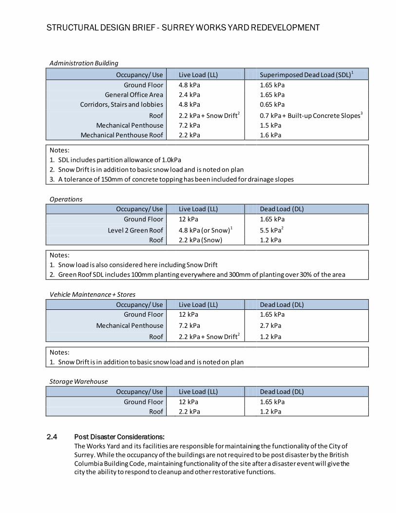
Notes: 1. SDL includes partition allowance of 1.0kPa 2. Snow Drift is in addition to basic snow load and is noted on plan 3. A tolerance of 150mm of concrete topping has been included for drainage slopes
Operations Occupancy/ Use Live Load (LL) Dead Load (DL)
Notes: 1. Snow Drift is in addition to basic snow load and is noted on plan
Storage Warehouse Occupancy/ Use Live Load (LL) Dead Load (DL)
Ground Floor 12 kPa 1.65 kPa Roof 2.2 kPa 1.2 kPa
2.4 Post Disaster Considerations: The Works Yard and its facilities are responsible for maintaining the functionality of the City of Surrey. While the occupancy of the buildings are not required to be post disaster by the British Columbia Building Code, maintaining functionality of the site after a disaster event will give the city the ability to respond to cleanup and other restorative functions.
STRUCTURAL DESIGN BRIEF - SURREY WORKS YARD REDEVELOPMENT
The Fleet maintenance + Stores building will be designed as the centre of emergency response and is designed considering post-disaster.
2.4.1 Design Considerations: Post disaster performance of a building is defined by the structures ability to maintain its function and safety during and after extreme environmental events. The following are some of the key design features to post-disaster structures: Factor of safety: The calculation of imposed environmental loads for the design of the Fleet Maintenance + Stores building has been increased by 25% for Snow, Rain and Wind loads and 50% for Earthquake. This increase in the imposed loading is a criteria defined in part 4 of the building code for “Post-Disaster” importance. Restricted Lateral Movement: During large wind and seismic events, damages to finishes, mechanical and electrical systems, are often due to excessive structural movements. In order to mitigate this type of failure, lateral movements are restricted to half of that for a “normal” building. Ductility: Seismic forces in a structure are actually inertial forces generated by the weight of a building moving with the ground. Large amounts of energy are created by the mass of the building and accelerations it feels during the event. To minimize damage due to these forces, the buildings lateral system must be capable of dissipating some of this energy. The ductility factor given for a specific lateral system is its ability to dissipate energy through deformation without sacrificing structural integrity.
2.5 Serviceability Requirements
Serviceability requirements will be checked against the requirements specified in the British Columbia Building Code and all other applicable reference standards including CSA Standards S16.1-01 Limit States Design of Steel Structures. The structural systems will be designed to meet the following criteria: Steel Structures Live Load Deflection Span/360 Wind Storey Drift Height/500 Seismic Storey Drift Normal Importance Height/40
Post-Disaster Importance Height/100
2.6 Geotechnical Considerations
A sub-surface investigation of the site was performed over two periods by GeoPacific Consultants Ltd. The results were documented in a preliminary report dated April 5, 2012 and a supplementary report dated February 19, 2013. A summary of their findings are below: The subsurface native soil consists of very stiff silt/clayey-silt that extends between 2.4 - 4.9m in depth underlain by a softer layer of clayey-silt that extends to a depth of between 3.0 - 8.7m. All of this is underlain by very dense glacial till like material. These results suggest that the foundations should bear either on the shallower stiff layer or the deep till layer. The
STRUCTURAL DESIGN BRIEF - SURREY WORKS YARD REDEVELOPMENT
geotechnical report recommends shallow conventional spread-footings with bearing capacities of 150kPa (SLS) and 225 kPa (ULS). The subsurface conditions also impact the ground movement characteristics of the site during a seismic event. This behaviour is represented in a site classification that is worked into design equations for calculating seismic forces. From the results of the subsurface investigation, the project site is a Site Class D.
2.6.1 Lateral Soil Pressures
The following values are typical values used in the design of earth retaining structures and are to be confirmed with the geotechnical engineer:
• Unit Weight of Backfill (free-draining granular material) = 20kN/m3 • Lateral Earth Pressure Coefficient (for vertical walls and horizontal backfill used for
permanent construction when water pressure is relieved by continuous wall drains) Ka=0.4.
Retaining walls are to be lined on the exterior face with a foundation drainage system to eliminate hydrostatic pressures.
2.7 LEED Strategies
Strategies related to LEED for building structures centre around maximizing recycled content, minimizing construction waste and total elimination and/or significant reduction in the use of materials containing VOC’s, and designed to accommodate future flexibility in design. For recycled content we propose a high amount of Supplementary Cementing Materials (SCMs) to be used in the foundations and walls, and a moderate amount of SCMs to be used in the concrete slab-on-grade and concrete-on-deck throughout the project.
3. STRUCTURAL SYSTEMS 3.1 Foundations
As recommended by the geotechnical report, the foundations for all buildings will be shallow conventional spread footings and strip footings bearing on native soil. The foundations supporting the Administration building are substantially larger than for the other buildings due to the increased weight demand. Foundations supporting the lateral resisting elements will be designed to prevent uplift and overturning due to seismic and wind loads. This will be achieved by placing them at a lower elevation in order to take advantage of the weight of soil above them. Grade beams will also tie lateral braces together at the foundations to share the lateral forces between each footing.
3.2 Slab-on-grade
The slab-on-grade thickness and reinforcing will vary for the different building and their use of space. Lightly loaded areas such as office and administration areas will be 100mm thick reinforced with welded-wire-fabric (steel mesh). Heavier loaded areas subject to more wear-and-tear such as workshop space will be 125mm thick, reinforced with a single layer of
STRUCTURAL DESIGN BRIEF - SURREY WORKS YARD REDEVELOPMENT
reinforcing bars. The Heaviest loaded areas such as the fleet maintenance garage bays will be 200mm thick reinforced with two layers of reinforcing. All slab-on-grades will bear on well compacted granular graded fill as recommended by the geotechnical report. Saw cuts and control joints will be used to control shrinkage cracks. Under stairs, partition walls and mechanical equipment we will have a 50mm slab thickening and additional reinforcing. Slab depressions, steps and ramps will be placed as required to accommodate interior elevations, equipment or furnishings.
3.3 Super Structure
3.3.1 Administration Building
The four-storey administration building is being designed as a cast-in-place reinforced concrete flat slab structure founded on conventional footings. On the roof there is a one storey mechanical penthouse A general breakdown in typical components follows:
The single storey Operations Centre is being designed with structural steel on conventional cast-in-place concrete foundations. A general breakdown in components follows:
• Roof system: Conventional: 38mm steel deck supported on a combination of beams of
varying depth and open-web-steel-joist. Landscaped: 89mm concrete on composite steel deck supported on composite
The lateral force resisting system of a building provides stability against wind and earthquake loading.
3.4.1 Eccentrically Braced Frames Eccentrically braced frames are an efficient and moderately stiff lateral system. They provide ductility through the use of a yielding link beam that dissipates energy and reduces the seismic impact on the building.
3.4.2 Moderately Ductile Shear Walls Ductile concrete shear walls are a very stiff and strong lateral system. Ductility is provided through flexural yielding at the first level. The design of the administration building utilizes strategically located shear walls optimized to reduce torsional effects and maximize flexibility.
3.5 Site Storage
The north side of the site consists of a combination of covered and uncovered storage. This will consist of cantilever retaining walls at the ends and back of the storage area. The separating
BRACE FRAME MEMBERS
GRADE BEAM
VOLUME OF EARTH RESISTING OVERTURNING
YIELD LINK - BEAM
STRUCTURAL DESIGN BRIEF - SURREY WORKS YARD REDEVELOPMENT
walls will most likely be pre-cast barrier type walls that allow flexibility in moving the walls. The covered area will likely consist of a reinforced concrete suspended slab supported with concrete columns in order to provide extra durability and toughness.
4. UNIQUE DESIGN CONSIDERATIONS
4.1 Movement Joints: Movement joints are introduced into the design as a way to laterally separate two sections of the same building. This is generally done for the following reasons:
4.1.1 Compatibility of the lateral force resisting system A movement joint is used to separate areas of a building that have different lateral force resisting systems in order to ensure that they don’t influence each others behaviour. This is particularly important in areas of different material or lateral systems of very different stiffness behaviour. For this reason we have introduced a moment joint between the concrete administration building with the operations centre. Figure 1. Detail of Movement joint between Administration Building and Operations Centre
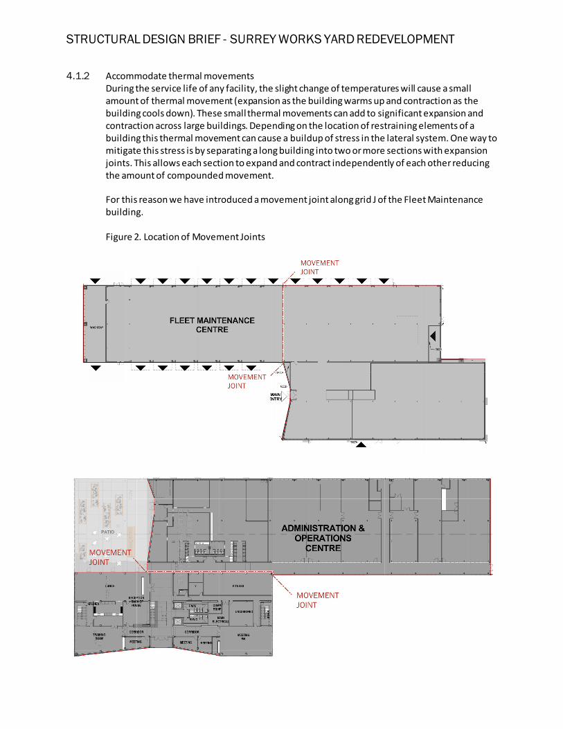
During the service life of any facility, the slight change of temperatures will cause a small amount of thermal movement (expansion as the building warms up and contraction as the building cools down). These small thermal movements can add to significant expansion and contraction across large buildings. Depending on the location of restraining elements of a building this thermal movement can cause a buildup of stress in the lateral system. One way to mitigate this stress is by separating a long building into two or more sections with expansion joints. This allows each section to expand and contract independently of each other reducing the amount of compounded movement. For this reason we have introduced a movement joint along grid J of the Fleet Maintenance building.
Figure 2. Location of Movement Joints
STRUCTURAL DESIGN BRIEF - SURREY WORKS YARD REDEVELOPMENT 4.2 Retaining Wall at Storage Warehouse
The finished floor of the Storage Warehouse building is being designed to be approximately 3m below grade along its North and East side. To reduce the size and thickness of the retaining wall, the design is based on active earth pressures, which means allowing certain flexibility in the retaining wall. This flexibility is greater than the design tolerance of the building, so the vertical structure will be independent of the foundation wall. Figure 3. Detail of Storage Warehouse Retaining Wall
4.3 Transfer Beams in Administration Building
The architectural form of the administration building features recessed cedar clad entranceways and balconies. These span across two or more column bays of the building. At these locations, perimeter columns have been removed to accommodate these perimeter
RETAINING WALL
ROOF SUPPORT COLUMN
CLADDING SUPPORT
STRUCTURAL DESIGN BRIEF - SURREY WORKS YARD REDEVELOPMENT
recesses. The column removal is to be supported by an upper floor transfer beam that hangs the floor below. This will enable a thin profile at the building edge for the cedar cladding. Figure 3. Detail of Typical Transfer beam in Administration Building