8

Steel Structures 7 (2007) 139-146 www.kssc.or.kr
Structural Design of a High-rise Building with Structural
Control System for Various Lateral Forces
Toshiyuki Tanaka1,*, Takeshi Katayama2 and Yukihiro Shimano2
1Business Promotion Department, Osaka Office, Takenaka Corporation 4-1-13, Honmachi, Chuou-ku, Osaka 541-0053, Japan2Building Design Department, Osaka Office, Takenaka Corporation 4-1-13, Honmachi, Chuou-ku, Osaka 541-0053, Japan
Abstract
This paper reports a recent application of the structural control system to a high-rise building (HARBIS ENT) built indowntown Osaka. The building has two types of structural control system, one for earthquakes and the other for strong winds.For earthquake control, the building is equipped with hysteretic steel dampers made of low-yield steel. The design concept,design criteria, and verification are presented. For wind control, the building is equipped with dampers made of high-dampingrubbers installed in the pre-cast concrete boards used on exterior walls. Numerical analyses are conducted to measure theenhanced habitability performance brought about by the introduction of the dampers.
Keywords: structural control, powerful earthquake, strong wind, hysteretic steel damper, high-damping rubber damper
1. Introduction
Japan has suffered countless disasters in its history as an
earthquake- and wind-prone country. Therefore, structural
engineers have been struggling with the issue of determining
how best to mitigate structural damage sustained by
buildings from such disasters. Lessons learned from the
1995 Hyogoken-Nanbu earthquake especially became a
catalyst to change structural engineering practices, one of
which is to consider the concentration or reduction of
damage in structural members to facilitate restoration
after an earthquake. This change led to the adoption of
structural control systems for performance improvement
during powerful earthquakes.
Although buildings are designed to be safe under strong
winds, this does not guarantee the inhabitants’ comfort.
Especially with the case of super high-rise buildings,
vibration control during strong winds has been a very
important issue.
In this paper, we report the latest structural design of a
high-rise building with a structural control system to
improve performance during powerful earthquakes and
strong winds.
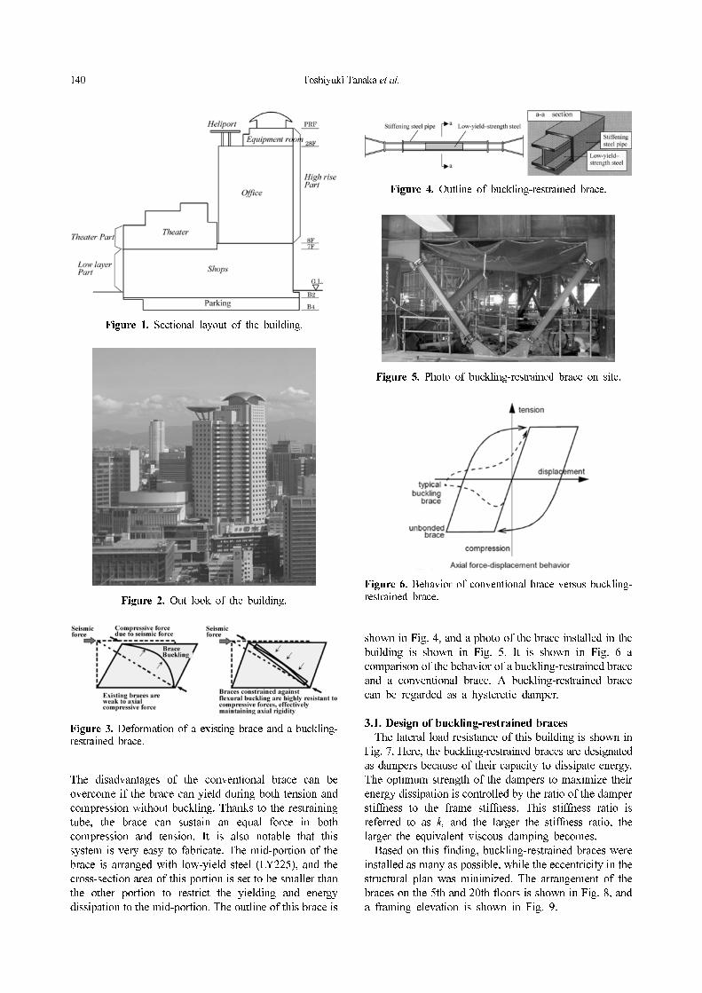
2. Building Outline
This building has 4 underground stories and 28 stories
above ground. The building complex has parking and
shops in underground floors, theater and shops in lower
floors above the ground, and office in floors 8-27 above
the ground. The outline of the building is shown in Table
1. The sectional layout and the out look of the building
are shown in Figs. 1 and 2, respectively.
3. Structural Control Design for Powerful Earthquakes
In this building, buckling-restrained braces are used for
the structural control system. The brace has a wide-flange
cross-section surrounded by a steel tube that prevents the
brace from buckling. The deformations of an ordinary
brace and a buckling-restrained brace are shown in Fig. 3.
*Corresponding authorTel: +81-6-6252-1201; Fax: +81-6-6263-5781E-mail: [email protected]
Technical Article
Table 1. Building description
Name HARBIS ENT
Location Osaka, Japan
Main useOffice, Theater, Shops
Total floor area 106,629.6 m2
Building area 6,241.5 m2
Height 138.6 m
Completion September, 2004
Floors 28 aboveground
4 underground
StructureColumns: Concrete-filled steel tube others: Steel
Natural periods X-dir 3.70s
Y-dir 3.69s
Torsional dir 4.18s
140 Toshiyuki Tanaka et al.
The disadvantages of the conventional brace can be
overcome if the brace can yield during both tension and
compression without buckling. Thanks to the restraining
tube, the brace can sustain an equal force in both
compression and tension. It is also notable that this
system is very easy to fabricate. The mid-portion of the
brace is arranged with low-yield steel (LY225), and the
cross-section area of this portion is set to be smaller than
the other portion to restrict the yielding and energy
dissipation to the mid-portion. The outline of this brace is
shown in Fig. 4, and a photo of the brace installed in the
building is shown in Fig. 5. It is shown in Fig. 6 a
comparison of the behavior of a buckling-restrained brace
and a conventional brace. A buckling-restrained brace
can be regarded as a hysteretic damper.
3.1. Design of buckling-restrained braces
The lateral load resistance of this building is shown in
Fig. 7. Here, the buckling-restrained braces are designated
as dampers because of their capacity to dissipate energy.
The optimum strength of the dampers to maximize their
energy dissipation is controlled by the ratio of the damper
stiffness to the frame stiffness. This stiffness ratio is
referred to as k, and the larger the stiffness ratio, the
larger the equivalent viscous damping becomes.
Based on this finding, buckling-restrained braces were
installed as many as possible, while the eccentricity in the
structural plan was minimized. The arrangement of the
braces on the 5th and 20th floors is shown in Fig. 8, and
a framing elevation is shown in Fig. 9.
Figure 1. Sectional layout of the building.
Figure 2. Out look of the building.
Figure 3. Deformation of a existing brace and a buckling-restrained brace.
Figure 4. Outline of buckling-restrained brace.
Figure 5. Photo of buckling-restrained brace on site.
Figure 6. Behavior of conventional brace versus buckling-restrained brace.
Structural Design of a High-rise Building with Structiral Control System for Various Lateral Forces 141
The cross-sectional areas of the buckling-restrained
braces were determined using the following processes:
(a) Determine the cross-sectional area of the portion of
the brace with low-yield steel so that optimum strength
can be achieved.
(b) Maximize brace stiffness by minimizing the length
of the smaller cross-section of the brace while maintaining
the length of its plastic deformation.
(c) Enlarge the cross-sectional area of the brace in the
other portion to increase the stiffness ratio k.
In addition to these design processes, plastic deformation
capacity of the buckling-restrained braces is controlled by
local buckling and fatigue fracture. For local buckling,
the brace’s flanges and web were selected so that
buckling would not occur under repeated loading. As for
fatigue fracture, cumulative ductility experienced by the
braces during their lifetime would not exceed the
allowable cumulative ductility. Based on the associated
fatigue tests, the braces adopted in the design would be
able to sustain a large earthquake twice and a medium-
scale earthquake four times.
3.2. Seismic response analysis for conformation of
seismic performance
Synthesized ground motions, all of which fit the
spectrum stipulated in Japan’s Building Standard Law,
were adopted for the time history analysis. The spectrum
was specified at the engineering bedrock located 50 m
below the ground level, and the subsurface amplification
of the motions was considered. In addition to the three
motions, three recorded ground motion, that is, the 1940
El Centro N-S component, 1952 Taft E-W component,
Figure 7. The lateral load resistance of the building withsteel hysteretic dampers.
Figure 8. Layouts of on the 5th floor and 20th floor.
Figure 9. Framing elevation.
Table 2. Ground motions for dynamic analysis
Ground motion types Ground motion V A Duaration(s)
Artificial ground motionobtained from the spectrumstipulated in the Notification
Artificial ground motion 1 53 356 120.0
Artificial ground motion 2 56 334 120.0
Artificial ground motion 3 61 366 120.0
Observed earthquake
El Centro 1940 NS 50 511 53.8
Taft 1952 EW 50 497 54.4
Hachinohe 1968 50 330 60.0
V: maximum velocity (cm/s), A: maximum acceleration (cm/s2)
142 Toshiyuki Tanaka et al.
and 1968 Hachinohe E-W component, were adopted. The
three ground motions were scaled so that the maximum
velocity would reach 0.5 m/s. The adopted ground motions
are summarized in Table 2, and their displacement
response spectra are shown in Fig. 10. Also, the criteria
adopted in design are summarized in Table 3.
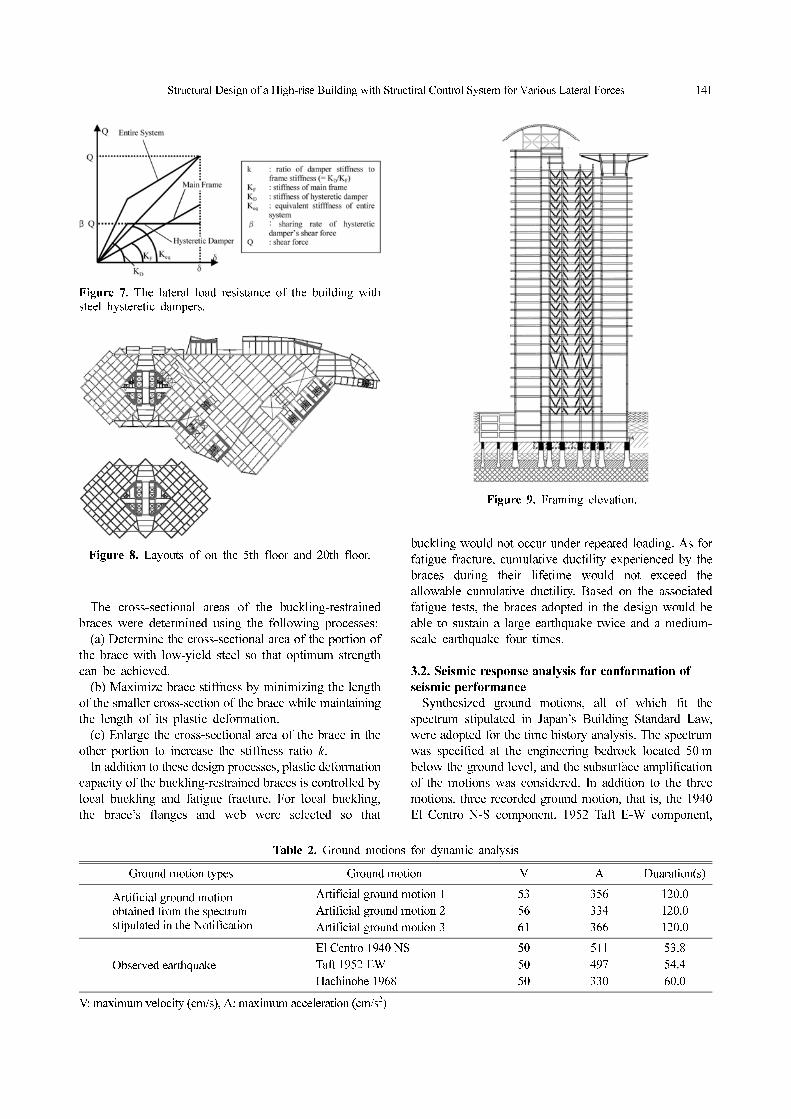
For the nonlinear time history analysis, a stick model
consisting of 39 lumped masses was used (Fig. 11). In
each story, shear stiffness was taken to be the sum of the
stiffness provided by the main frame and the stiffness
provided by the buckling-restrained braces. In order to
obtain the backbone curve, which in turn was used to
specify the story hysteresis, nonlinear push-over analyses
were performed. The backbone curve of the 15th story is
shown in Fig. 12.
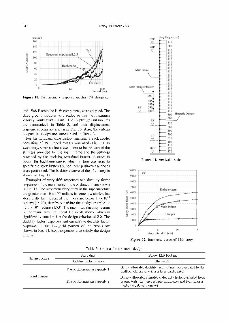
Examples of story drift responses and ductility factor
responses of the main frame in the X-direction are shown
in Fig. 13. The maximum story drifts in the superstructure
are greater than 10 × 10−3 radians in some low stories, but
story drifts for the rest of the floors are below 10 × 10−3
radians (1/100), thereby satisfying the design criterion of
12.0 × 10⁻³ radians (1/83). The maximum ductility factors
of the main frame are about 1.5 in all stories, which is
significantly smaller than the design criterion of 2.0. The
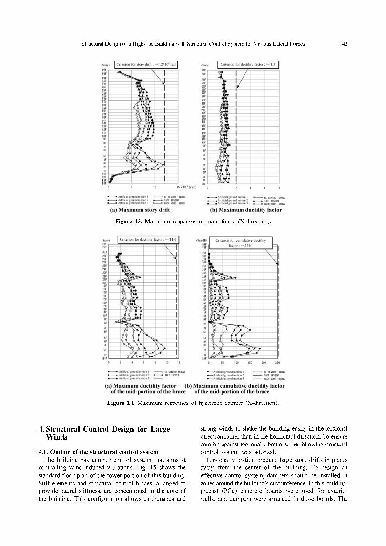
ductility factor responses and cumulative ductility factor
responses of the low-yield portion of the braces are
shown in Fig. 14. Both responses also satisfy the design
criteria.
Table 3. Criteria for structural design
SuperstructureStory drift Below 12.0 10-3 rad
Ductility factor of story Below 2.0
Steel damper
Plastic deformation capacity 1Below allowable ductility factor of number evaluated by the width-thickness ratio (for a large earthquake)
Plastic deformation capacity 2Bellow allowable cumulative ductility factor evaluated from fatigue tests (for twice a large earthquake and four times a medium-scale earthquake)
Figure 10. Displacement response spectra (5% damping).
Figure 11. Analysis model.
Figure 12. Backbone curve of 15th story.
Structural Design of a High-rise Building with Structiral Control System for Various Lateral Forces 143
4. Structural Control Design for Large Winds
4.1. Outline of the structural control system
The building has another control system that aims at
controlling wind-induced vibrations. Fig. 15 shows the
standard floor plan of the tower portion of this building.
Stiff elements and structural control braces, arranged to
provide lateral stiffness, are concentrated in the core of
the building. This configuration allows earthquakes and
strong winds to shake the building easily in the torsional
direction rather than in the horizontal direction. To ensure
comfort against torsional vibrations, the following structural
control system was adopted.
Torsional vibration produce large story drifts in places
away from the center of the building. To design an
effective control system, dampers should be installed in
zones around the building’s circumference. In this building,
precast (PCa) concrete boards were used for exterior
walls, and dampers were arranged in those boards. The
Figure 13. Maximum responses of main frame (X-direction).
Figure 14. Maximum responses of hysteretic damper (X-direction).

144 Toshiyuki Tanaka et al.
dampers were designed to be installed in a symmetricalpattern on the 16 stories of the tower section from the12th floor to the 27th floor. A total of 256 dampers wereinstalled on the PCa boards. Generally, tuned massdampers (TMDs) or active mass dampers (AMDs) wouldhave been adopted to control vibrations. However, to beeffective against torsional vibrations, at least two suchdevices would have been needed to be installed on theroof. The roof of this building has an unsymmetrical plan,which made the application of such devices unfeasible.For this reason, a control system with PCa boards wasadopted in this building.
4.2. Design consideration
The design concept of this structural control system isas follows:
(a) For strong winds that are expected once a year, thehabitability criteria specified for offices in the EvaluationGuidelines of the Architectural Institute of Japan (AIJ)should be satisfied.
(b) For powerful earthquakes that are expected aboutonce every 500 years, the exterior walls should not falloff and structural control devices should not be damaged.
The velocity of strong winds expected once a year isestimated statistically based on the design guidelines of
the AIJ. The maximum wind speed (given as the averageover ten minutes) at the top of the building is calculatedas 20.0m/s by the following equation:
UH=139.8 = V1Å~(139.8/53)0.27 = 20.0 m/sUH: The wind speed for examination of habitability (m/s)V1: The wind speed (=15.4m/s), expected once a year
in the Osaka observatory (for the measurement height of53.0 m)
Classification of habitability performance is listed inTable 4. Fig. 16 is used to judge the vibration levels,classified as H-1, H-2, H-3 and H-4. The target level ofvibrations was chosen as H-3, because the tower part ofthis building is used as offices for which the target of rankis “Rank II” in most cases.
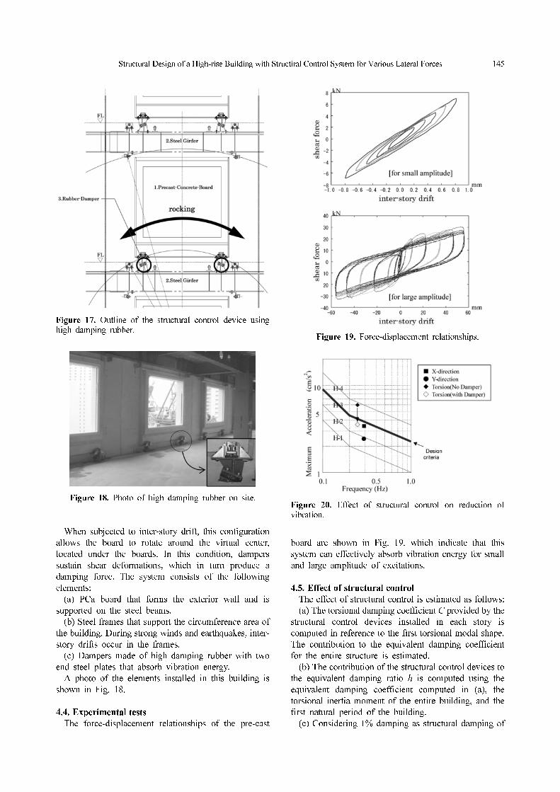
4.3. Outline of the structural control device
The outline of the structural control system is shown inFig. 17. Two high damping rubber dampers are used tosupport an exterior wall made of PCa board.
Figure 15. Standard floor plan at the higher-rise part of the building.
Table 4. Ground motions for dynamic analysis
RankUse
I II III
Residence H-1 H-2 H-3
Office H-2 H-3 H-4
‘Rank’ indicates level of comfortableness, and generally it issettled ‘rank-II’. Figure 16. Evaluation of habitability performance.
Structural Design of a High-rise Building with Structiral Control System for Various Lateral Forces 145
When subjected to inter-story drift, this configuration
allows the board to rotate around the virtual center,
located under the boards. In this condition, dampers
sustain shear deformations, which in turn produce a
damping force. The system consists of the following
elements:
(a) PCa board that forms the exterior wall and is
supported on the steel beams.
(b) Steel frames that support the circumference area of
the building. During strong winds and earthquakes, inter-
story drifts occur in the frames.
(c) Dampers made of high damping rubber with two
end steel plates that absorb vibration energy.
A photo of the elements installed in this building is
shown in Fig. 18.
4.4. Experimental tests
The force-displacement relationships of the pre-cast
board are shown in Fig. 19, which indicate that this
system can effectively absorb vibration energy for small
and large amplitude of excitations.
4.5. Effect of structural control
The effect of structural control is estimated as follows:
(a) The torsional damping coefficient C provided by the
structural control devices installed in each story is
computed in reference to the first torsional modal shape.
The contribution to the equivalent damping coefficient
for the entire structure is estimated.
(b) The contribution of the structural control devices to
the equivalent damping ratio h is computed using the
equivalent damping coefficient computed in (a), the
torsional inertia moment of the entire building, and the
first natural period of the building.
(c) Considering 1% damping as structural damping of
Figure 17. Outline of the structural control device usinghigh damping rubber.
Figure 18. Photo of high damping rubber on site.
Figure 19. Force-displacement relationships.
Figure 20. Effect of structural control on reduction ofvibration.

146 Toshiyuki Tanaka et al.
the building itself, the rate of acceleration reduction that
can be expected from the equivalent damping ratio h is
estimated by the following equation.
(%) (1)
The effects of the dampers calculated by Eq. (1) are
shown in Fig. 20, which indicates that the target “H-3”
habitability criteria are satisfied for torsional vibrations.
5. Conclusion
The conclusion is as follows:
(1) The authors applied a structural control system with
hysteretic steel dampers and high-damping rubber dampers
to a high-rise building
(2) Numerical analyses were performed and performance
caused by the introduction of the structural control system
during powerful earthquakes and during strong winds has
been verified.
The application of a structural control system is fast
becoming popularly adopted in Japan. This trend results
from building owners’ gradual recognition of the benefits
of these systems for enhanced seismic safety and comfort
as good performance during an earthquake or strong wind
is greatly needed. Structural engineers are committed to
finding solutions for these needs. This situation also
implies the development of a new method for good
performance and good value.
References
Goto, T. et al. (1991), Guidelines for the Evaluation of
Habitability to Building Vibration, Architectural Institute
of Japan.
Inoue, K. (1995). “Seismic design of the building installed
hysteretic damper,” Proceedings of One New Direction of
Seismic Design Symposium, Architectural Institute of
Japan, pp. 95-109.
Yoshinobu, O., Hirofumi, K., Naomiki, S. (2000). “Fatigue
characteristic of H-shaped brace damper constrained
flexural buckling,” Proceedings of the Second Japan
National Symposium on Structural control, pp. 531-536.
1 1 h+ 100×⁄


