American Institute of Aeronautics and Astronautics 1 STRUCTURAL DESIGN OF ARES V INTERSTAGE COMPOSITE STRUCTURE David W. Sleight 1 NASA Langley Research Center, Hampton, VA, 23681 Thammaiah Sreekantamurthy 2 ATK Space Division, Hampton, VA, 23681 Daniel N. Kosareo 3 ASRC Aerospace Corp, Cleveland, OH, 44135 Robert A. Martin 4 and Theodore F. Johnson 5 NASA Langley Research Center, Hampton, VA, 23681 Preliminary and detailed design studies were performed to mature composite structural design concepts for the Ares V Interstage structure as a part of NASA’s Advanced Composite Technologies Project. Aluminum honeycomb sandwich and hat-stiffened composite panel structural concepts were considered. The structural design and analysis studies were performed using HyperSizer design sizing software and MSC Nastran finite element analysis software. System-level design trade studies were carried out to predict weight and margins of safety for composite honeycomb-core sandwich and composite hat- stiffened skin design concepts. Details of both preliminary and detailed design studies are presented in the paper. For the range of loads and geometry considered in this work, the hat-stiffened designs were found to be approximately 11-16 percent lighter than the sandwich designs. A down-select process was used to choose the most favorable structural concept based on a set of figures of merit, and the honeycomb sandwich design was selected as the best concept based on advantages in manufacturing cost. I. Introduction HE Ares V launch vehicle was a key component in NASA’s Constellation Program. The Constellation Program was NASA’s human spaceflight program and was officially cancelled in October 2010. The Ares V was intended for delivery of large-scale hardware to space; hence it was designed for the requirements of a cargo launch vehicle. The ARES V was a two-stage rocket that consisted of a Core Stage and an Earth Departure Stage (EDS). The major dry (not tankage) structural components of the ARES V vehicle are shown in Figure 1. These components include the Payload Shroud, Interstage, and Intertank along with two recoverable solid rocket boosters. The Payload Shroud structure is on top of the vehicle and is 33.0 ft in diameter and 77.8 ft long. The 33.0 ft diameter, 44.6 ft long cylindrical Interstage joins the EDS to the Core Stage and incorporates an integral separation mechanism for staging. The 33.0 ft diameter, 27.5 ft long Core Stage Intertank is located between the Core Stage liquid oxygen and liquid hydrogen tanks. NASA’s Exploration Technology Development Program (ETDP) initiated the Advanced Composite Technologies (ACT) Project to develop composite structural concepts and technologies for the Payload Shroud, Interstage, and Intertank with a goal of reducing structural weight, while maintaining the same structural performance as advanced metallic component designs. The ACT structural concepts development work was carried out by a team of engineers from six NASA centers including Ames, Glenn, and Langley Research Centers, Goddard Space Flight Center, Kennedy Space Center, and Marshall Space Flight Center. The team collaborated with engineers from the aerospace industry, including representatives from Boeing, Northrop Grumman, ATK, Lockheed Martin, and Collier Research Corporation. The 1 Aerospace Engineer, Durability, Damage Tolerance, & Reliability Branch, MS 188E, AIAA Senior Member. 2 Senior Structural Engineer, ATK Space Division, MS 230, Structural Dynamics Branch, NASA Langley. 3 Mechanical Engineer, ASRC Aerospace Corp., 21000 Brookpark Rd., Cleveland, OH 44135, AIAA Member. 4 Aerospace Engineer, Mechanical Systems Branch, MS 432. 5 Assistant Branch Head, Structural & Thermal Systems Branch, MS 431, AIAA Senior Member. T https://ntrs.nasa.gov/search.jsp?R=20110010308 2018-05-21T19:54:39+00:00Z
Transcript
American Institute of Aeronautics and Astronautics
1
STRUCTURAL DESIGN OF ARES V INTERSTAGE COMPOSITE STRUCTURE
David W. Sleight1 NASA Langley Research Center, Hampton, VA, 23681
Thammaiah Sreekantamurthy2 ATK Space Division, Hampton, VA, 23681
Daniel N. Kosareo3 ASRC Aerospace Corp, Cleveland, OH, 44135
Robert A. Martin4 and Theodore F. Johnson5 NASA Langley Research Center, Hampton, VA, 23681
Preliminary and detailed design studies were performed to mature composite structural design concepts for the Ares V Interstage structure as a part of NASA’s Advanced Composite Technologies Project. Aluminum honeycomb sandwich and hat-stiffened composite panel structural concepts were considered. The structural design and analysis studies were performed using HyperSizer design sizing software and MSC Nastran finite element analysis software. System-level design trade studies were carried out to predict weight and margins of safety for composite honeycomb-core sandwich and composite hat-stiffened skin design concepts. Details of both preliminary and detailed design studies are presented in the paper. For the range of loads and geometry considered in this work, the hat-stiffened designs were found to be approximately 11-16 percent lighter than the sandwich designs. A down-select process was used to choose the most favorable structural concept based on a set of figures of merit, and the honeycomb sandwich design was selected as the best concept based on advantages in manufacturing cost.
I. Introduction
HE Ares V launch vehicle was a key component in NASA’s Constellation Program. The Constellation Program was NASA’s human spaceflight program and was officially cancelled in October 2010. The Ares V was
intended for delivery of large-scale hardware to space; hence it was designed for the requirements of a cargo launch vehicle. The ARES V was a two-stage rocket that consisted of a Core Stage and an Earth Departure Stage (EDS). The major dry (not tankage) structural components of the ARES V vehicle are shown in Figure 1. These components include the Payload Shroud, Interstage, and Intertank along with two recoverable solid rocket boosters. The Payload Shroud structure is on top of the vehicle and is 33.0 ft in diameter and 77.8 ft long. The 33.0 ft diameter, 44.6 ft long cylindrical Interstage joins the EDS to the Core Stage and incorporates an integral separation mechanism for staging. The 33.0 ft diameter, 27.5 ft long Core Stage Intertank is located between the Core Stage liquid oxygen and liquid hydrogen tanks. NASA’s Exploration Technology Development Program (ETDP) initiated the Advanced Composite Technologies (ACT) Project to develop composite structural concepts and technologies for the Payload Shroud, Interstage, and Intertank with a goal of reducing structural weight, while maintaining the same structural performance as advanced metallic component designs. The ACT structural concepts development work was carried out by a team of engineers from six NASA centers including Ames, Glenn, and Langley Research Centers, Goddard Space Flight Center, Kennedy Space Center, and Marshall Space Flight Center. The team collaborated with engineers from the aerospace industry, including representatives from Boeing, Northrop Grumman, ATK, Lockheed Martin, and Collier Research Corporation. The
1 Aerospace Engineer, Durability, Damage Tolerance, & Reliability Branch, MS 188E, AIAA Senior Member. 2 Senior Structural Engineer, ATK Space Division, MS 230, Structural Dynamics Branch, NASA Langley. 3 Mechanical Engineer, ASRC Aerospace Corp., 21000 Brookpark Rd., Cleveland, OH 44135, AIAA Member. 4 Aerospace Engineer, Mechanical Systems Branch, MS 432. 5 Assistant Branch Head, Structural & Thermal Systems Branch, MS 431, AIAA Senior Member.
American Institute of Aeronautics and Astronautics
2
ACT team evaluated several composite structural concepts to assess basic structural performance of the Payload Shroud, Interstage, and Intertank structural components in terms of analytically predicted weight, margins of safety on stresses and buckling, and other structural factors. Objectivity of the process for comparing structural concepts was assured by use of a set of figures of merit based on design considerations to capture considerations for mass, cost, damage tolerance, manufacturability, repairability, inspectability, technological maturity, and the ease of adding secondary attachments. The best two concepts were carried forward for detailed study. A documentation of the studies done for the Payload Shroud and Intertank can be found in Refs. 1-5.
The purpose of this paper is to describe the structural design studies that were performed to develop a composite
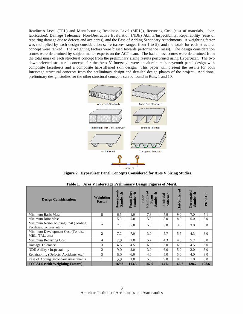
Interstage for the Ares V under the ACT Project. The composite structural design concepts, as shown in Figure 2, initially considered for the Interstage design were:
1. Aluminum honeycomb core sandwich 2. Foam core sandwich 3. Fiber reinforced foam core sandwich (Ref 6) 4. Uniaxially-stiffened skin (I-beam stiffeners) 5. Hat-stiffened skin 6. Corrugated sandwich 7. Boeing’s PRSEUS (Pultruded Rod Stitched Efficient Unitized Structure) (Ref. 7) The structural sizing of these concepts in the preliminary design study of the Interstage was performed using the
HyperSizer® (Ref. 8) structural sizing software, in conjunction with MSC NastranTM (Ref. 9) finite element analyses (FEA), to determine the acreage mass for each panel concept. In the final stage of the ACT Project, two leading concepts were selected for detailed design and sizing based on a set of figures of merit for various design considerations as shown in Table 1. The design considerations chosen for the Interstage were: Basic Mass, Joint Mass, Non-Recurring Cost (tooling, facilities, fixtures, etc.), Development Cost (cost to increase Technology
Figure 1. Ares V Heavy Lift Vehicle.
Payload Shroud
Altair Lunar Lander
Payload Adapter
Loiter SkirtInterstage534.6 in L33 ft dia
RS-68B Engines (6)
Two 5.5-segmented Recoverable Solid Rocket Boosters
Earth Departure Stage (EDS)• One Saturn-derived J-2X LOX/LH2 engine• Aluminum-Lithium (Al-Li) tanks• 10 m (33 ft) diameter
J-2X Engine
Core Stage• Six Delta IV-derived RS-68B LOX/LH2 engines• Aluminum-Lithium (Al-Li) tanks• 10 m (33 ft) diameter
Core Intertank
American Institute of Aeronautics and Astronautics
3
Readiness Level (TRL) and Manufacturing Readiness Level (MRL)), Recurring Cost (cost of materials, labor, fabrication), Damage Tolerance, Non-Destructive Evalulation (NDE) Ability/Inspectibility, Repairability (ease of repairing damage due to defects and accidents), and the Ease of Adding Secondary Attachments. A weighting factor was multiplied by each design consideration score (scores ranged from 1 to 9), and the totals for each structural concept were ranked. The weighting factors were biased towards performance (mass). The design consideration scores were determined by subject matter experts on the ACT team. The basic mass scores were determined from the total mass of each structural concept from the preliminary sizing results performed using HyperSizer. The two down-selected structural concepts for the Ares V Interstage were an aluminum honeycomb panel design with composite facesheets and a composite hat-stiffened skin design. This paper will present the results for both Interstage structural concepts from the preliminary design and detailed design phases of the project. Additional preliminary design studies for the other structural concepts can be found in Refs. 1 and 10.
Table 1. Ares V Interstage Preliminary Design Figures of Merit.
Figure 2. HyperSizer Panel Concepts Considered for Ares V Sizing Studies.
American Institute of Aeronautics and Astronautics
4
II. Structural Design Methodology and Modeling
Structural models used in this work were developed with MSC PatranTM (Ref. 11), and analyzed using the MSC Nastran finite element analysis software in conjunction with the HyperSizer structural sizing software. In using HyperSizer, the finite element (FE) model is subdivided into several groups of elements, internally referred to as “components”, each sharing a common material property set. For each component, the user defines a design space by selecting the beam type (i.e., I-beam, C-beam, T-beam) or panel type (i.e., hat-stiffened, honeycomb sandwich, orthogrid) and sets the upper and lower limits on geometric parameters (i.e., beam height, panel height, facesheet thickness, web spacing) and the number of permutations to consider for each geometric parameter. In addition, the user defines the dimensions and radius of curvature for each panel or beam, and the materials to be considered for each component. HyperSizer interfaces with MSC Nastran in the sizing process by retrieving the finite element analysis (FEA) element forces from the Nastran output file and then using these forces to size each structural component via closed-form methods for a wide range of strength- and stability-based failure criteria. The lightest candidate beam or panel design that has all positive margins for all chosen failure modes in all load cases is then selected as the optimal design. After completion of a sizing analysis, HyperSizer updates material properties in the FE model for components that have changed. The updated model is reanalyzed in Nastran and a new distribution of element forces is obtained. This procedure is repeated multiple times until a user-defined level of convergence for the weight has been achieved. The following sections discuss the details of the preliminary and detailed design FE structural models.
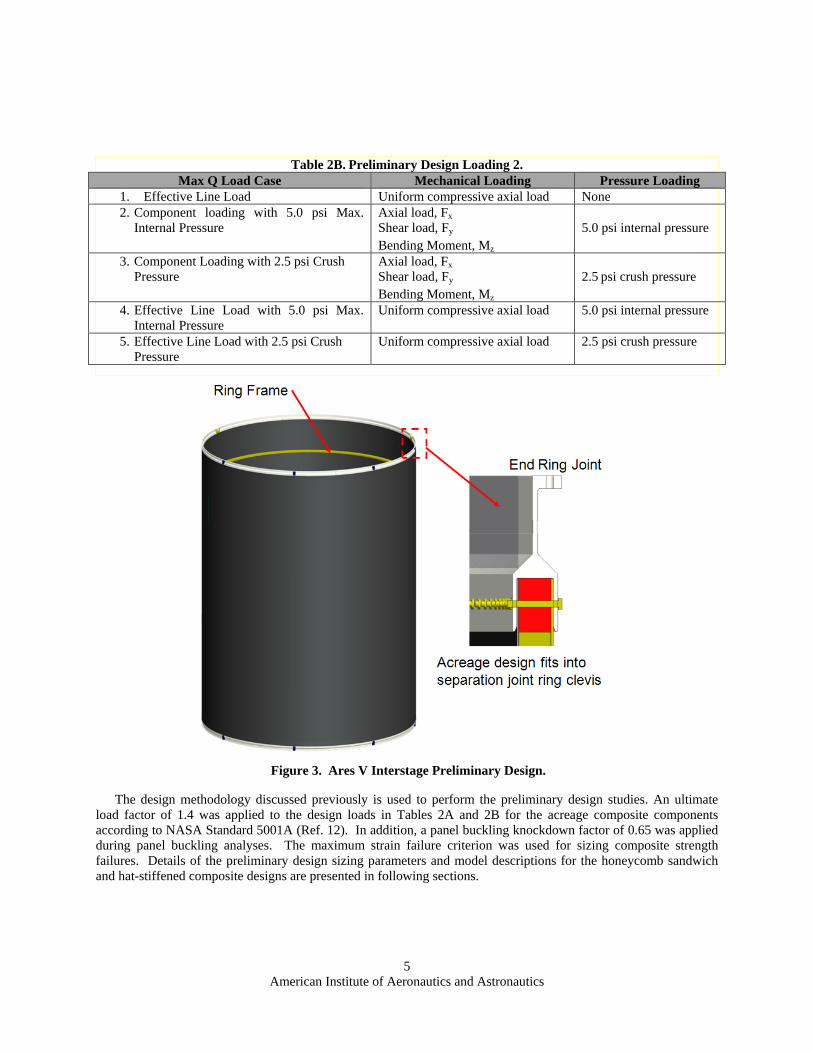
A. Preliminary Design Structural Models In the preliminary design of the Ares V Interstage structure, the geometry of the Interstage was 47.5 ft long with
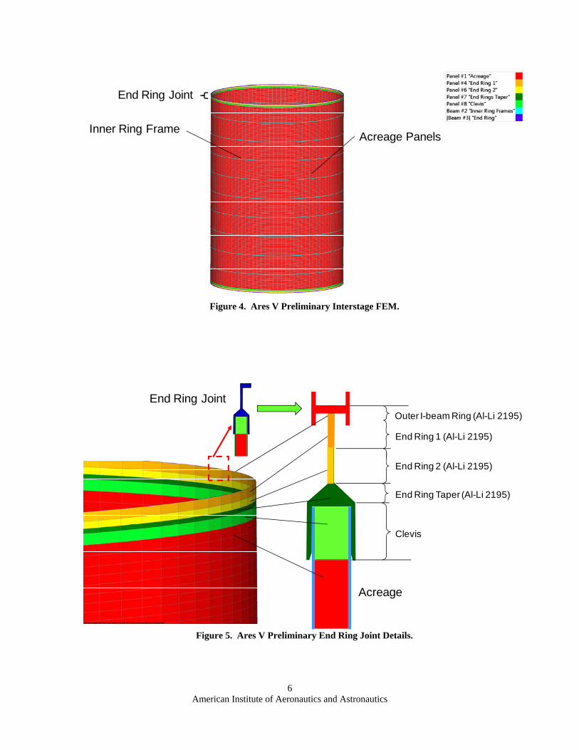
a diameter of 33 feet. A schematic of the initial Interstage design is shown in Figure 3. Multiple FE models were developed with varying number of internal ring frames (from 1 to 18). These models were used to size both panel concepts. A typical FE model used in the sizing of a ring-stiffened concept (9 ring frames spaced on 58-inch centers) is shown in Figure 4. Details of the end ring joint are shown in Figure 5. Shell elements were used to model the acreage panels and the end ring joint components. Beam elements were used to model the inner ring frames and the flange of the end ring joint. Preliminary studies focused on design of the acreage (panels and inner ring frames) and the end ring joint. Three initial load cases were used for preliminary design. These corresponded to a maximum dynamic pressure load (max Q) during ascent as listed in Table 2A. Two additional load cases were added later in the preliminary design process as listed in Table 2B. The magnitudes of these loads were not releasable. Load introduction extension structures 60” long (see Fig. 6) were added to the forward and aft ends of the Interstage using a direct matrix input at grid points (DMIG) in Nastran to simulate the boundary conditions of the forward and aft skirt structures attached to the Interstage. The stiffness of the DMIG extension structures was approximately 1.5 times the stiffness of the acreage panels of the Interstage structure to force any buckling failures to occur in the Interstage structure. The max Q loads were applied to the FE model at the top of the extension structure using a rigid body element (RBE2). The axial (z) and tangential () translational degrees of freedom of the bottom nodes of the lower extension structure were constrained, using a cylindrical analysis coordinate system. Composite material properties were based on IM7/8552 unidirectional carbon/epoxy prepreg tape. Open hole compression allowables were used in the preliminary sizing study for strength-based failure criteria. Metallic material properties were those of aluminum lithium alloy 2195-T8. Due to expected elevated temperatures during flight, material properties at 120 °F were used.
Table 2A. Preliminary Design Loading 1. Max Q Load Case Mechanical Loading Pressure Loading
1. Effective Line Load Uniform compressive axial load None 2. Component loading with 5.0 psi Max.
Internal Pressure Axial load, Fx Shear load, Fy
Bending Moment, Mz
5.0 psi internal pressure
3. Component Loading with 2.5 psi Crush Pressure
Axial load, Fx Shear load, Fy
Bending Moment, Mz
2.5 psi crush pressure
American Institute of Aeronautics and Astronautics
5
The design methodology discussed previously is used to perform the preliminary design studies. An ultimate
load factor of 1.4 was applied to the design loads in Tables 2A and 2B for the acreage composite components according to NASA Standard 5001A (Ref. 12). In addition, a panel buckling knockdown factor of 0.65 was applied during panel buckling analyses. The maximum strain failure criterion was used for sizing composite strength failures. Details of the preliminary design sizing parameters and model descriptions for the honeycomb sandwich and hat-stiffened composite designs are presented in following sections.
Figure 3. Ares V Interstage Preliminary Design.
Table 2B. Preliminary Design Loading 2. Max Q Load Case Mechanical Loading Pressure Loading
1. Effective Line Load Uniform compressive axial load None 2. Component loading with 5.0 psi Max.
American Institute of Aeronautics and Astronautics
6
Figure 5. Ares V Preliminary End Ring Joint Details.
End Ring Joint
End Ring 1 (Al-Li 2195)
End Ring 2 (Al-Li 2195)
End Ring Taper (Al-Li 2195)
Clevis
Acreage
Outer I-beam Ring (Al-Li 2195)
Figure 4. Ares V Preliminary Interstage FEM.
Inner Ring FrameAcreage Panels
End Ring Joint
American Institute of Aeronautics and Astronautics
7
1. Honeycomb Sandwich Design For the honeycomb sandwich preliminary design, Hexcel (Ref. 13) aluminum 5052 (3.1 - 6.0 lb/ft3) was used for
the sandwich core with a thickness ranging from 1.0 to 2.5 inches. The composite facesheets varied in thickness from 0.0684 inches (12 plies) to 0.1026 inches (18 plies). The 12 ply minimum facesheet thickness was imposed for damage tolerance, penetrations, and joint design considerations. The internal ring frames were selected to be composite I-beams with heights ranging from 4 to 14 inches, flange lengths ranging from 2 to 6 inches, and flange and web thicknesses ranging from 12 to 26 plies.
2. Hat-Stiffened Design
For the hat-stiffened preliminary design, external hat stiffeners were recommended rather than internal hat stiffeners on the Interstage barrel for ease in manufacturing. The thickness of the skin ranged from 0.0684 inches (12 plies) to 0.1140 inches (20 plies), and the panel heights ranged from 1.6 to 3 inches. The crown thickness of the hat-stiffeners ranged from 0.0684 inches (12 plies) to 0.1482 inches (26 plies) and the hat-stiffener spacing ranged from 4 to 7 inches. The internal ring frames were selected to be composite C-beams using the IM7/8552 composite material with heights ranging from 4 to 16 inches, flange lengths ranging from 2 to 6 inches, and flange and web thicknesses ranging from 12 to 26 plies. C-beams were selected based on earlier trade study results which showed that the C-beams had the minimum ring frame weight if fastener weights were taken into consideration.
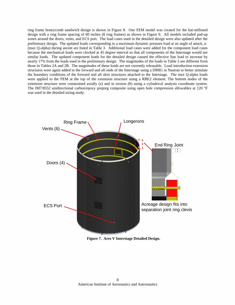
B. Detailed Design Structural Models In the detailed design of the Ares V Interstage structure, the length of the Interstage was shortened slightly under
the direction of the Constellation Program to 44.6 ft long, while retaining the 33-ft diameter. The detailed model for the hat-stiffened design, shown in Figure 7, included four doors (36 x 36 inches in size and located 180 apart) for access to the Interstage during manufacturing and vehicle assembly, six vent holes, and one Environmental Control System (ECS) port. Longerons running between the ring frames were placed on both sides of the doors to distribute the loads efficiently around the doors. Three FEMs were created for the detailed Interstage design based on the results of the preliminary design study. The models included two FEMs for the honeycomb sandwich design with internal ring frame spacings of 78 inches (6 ring frames) and 134 inches (3 ring frames). The FEM model for the 6
Figure 6. Ares V Preliminary FEM Loading and Boundary Conditions.
Ring Frames
60” DMIG FWD Skirt
60” DMIG AFT Skirt
Interstage
Loading applied with RBE2 “wagon-wheel” approach
Bottom: = Z = 0
R
Z
Fx
Fy
Mz
American Institute of Aeronautics and Astronautics
8
ring frame honeycomb sandwich design is shown in Figure 8. One FEM model was created for the hat-stiffened design with a ring frame spacing of 60 inches (8 ring frames) as shown in Figure 9. All models included pad-up zones around the doors, vents, and ECS port. The load cases used in the detailed design were also updated after the preliminary design. The updated loads corresponding to a maximum dynamic pressure load at an angle of attack, (max Q-alpha) during ascent are listed in Table 3. Additional load cases were added for the component load cases because the mechanical loads were clocked at 45 degree interval so that all components of the Interstage would see similar loads. The updated component loads for the detailed design caused the effective line load to increase by nearly 17% from the loads used in the preliminary design. The magnitudes of the loads in Table 3 are different from those in Tables 2A and 2B. The magnitudes of these loads are not currently releasable. Load introduction extension structures were again added to the forward and aft ends of the Interstage using a DMIG in Nastran to better simulate the boundary conditions of the forward and aft skirt structures attached to the Interstage. The max Q-alpha loads were applied to the FEM at the top of the extension structure using a RBE2 element. The bottom nodes of the extension structure were constrained axially (z) and in torsion () using a cylindrical analysis coordinate system. The IM7/8552 unidirectional carbon/epoxy prepreg composite using open hole compression allowables at 120 °F was used in the detailed sizing study.
Figure 7. Ares V Interstage Detailed Design.
Acreage design fits into separation joint ring clevis
End Ring Joint
Doors (4)
ECS Port
Vents (6)
Ring Frame Longerons
American Institute of Aeronautics and Astronautics
9
Figure 9. Hat-Stiffened 8-Ring Frame Interstage Detailed Finite Element Model.
American Institute of Aeronautics and Astronautics
10
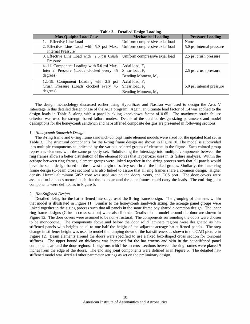
The design methodology discussed earlier using HyperSizer and Nastran was used to design the Ares V Interstage in this detailed design phase of the ACT program. Again, an ultimate load factor of 1.4 was applied to the design loads in Table 3, along with a panel buckling knockdown factor of 0.65. The maximum strain failure criterion was used for strength-based failure modes. Details of the detailed design sizing parameters and model descriptions for the honeycomb sandwich and hat-stiffened composite designs are presented in following sections.
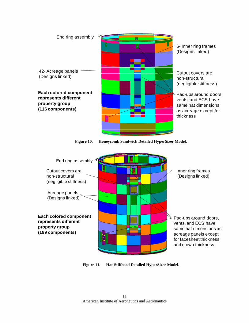
1. Honeycomb Sandwich Design
The 3-ring frame and 6-ring frame sandwich-concept finite element models were sized for the updated load set in Table 3. The structural components for the 6-ring frame design are shown in Figure 10. The model is subdivided into multiple components as indicated by the various colored groups of elements in the figure. Each colored group represents elements with the same property set. Subdividing the Interstage into multiple components between the ring frames allows a better distribution of the element forces that HyperSizer uses in its failure analyses. Within the acreage between ring frames, element groups were linked together in the sizing process such that all panels would have the same design based on the lowest margin of safety seen in all the linked groups. Similarly, the inner ring frame design (C-beam cross section) was also linked to assure that all ring frames share a common design. Higher density Hexcel aluminum 5052 core was used around the doors, vents, and ECS port. The door covers were assumed to be non-structural such that the loads around the door frames could carry the loads. The end ring joint components were defined as in Figure 5.
2. Hat-Stiffened Design
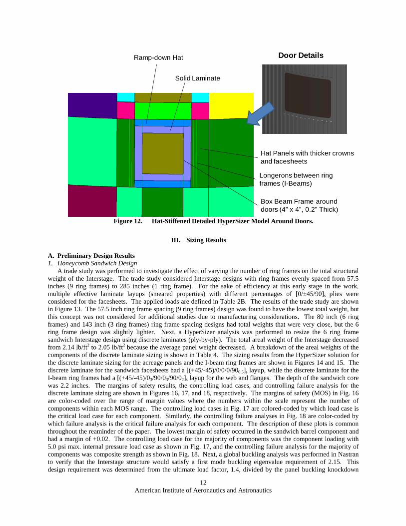
Detailed sizing for the hat-stiffened Interstage used the 8-ring frame design. The grouping of elements within that model is illustrated in Figure 11. Similar to the honeycomb sandwich sizing, the acreage panel groups were linked together in the sizing process such that all panels in the same frame bay shared a common design. The inner ring frame designs (C-beam cross section) were also linked. Details of the model around the door are shown in Figure 12. The door covers were assumed to be non-structural. The components surrounding the doors were chosen to be monocoque. The components above and below the door solid laminate regions were designated as hat-stiffened panels with heights equal to one-half the height of the adjacent acreage hat-stiffened panels. The step change in stiffener height was used to model the ramping down of the hat-stiffeners as shown in the CAD picture in Figure 12. Beam elements around the doors were specified to use a fixed box-shaped cross section for torsional stiffness. The upper bound on thickness was increased for the hat crowns and skin in the hat-stiffened panel components around the door regions. Longerons with I-beam cross sections between the ring frames were placed 9 inches from the edge of the doors. The end ring joint components were defined as in Figure 5. The detailed hat-stiffened model was sized all other parameter settings as set on the preliminary design.
Table 3. Detailed Design Loading. Max Q-alpha Load Case Mechanical Loading Pressure Loading
1. Effective Line Load Uniform compressive axial load None 2. Effective Line Load with 5.0 psi Max.
Each colored component represents different property group(116 components)
Cutout covers are non-structural (negligible stiffness)
Pad-ups around doors, vents, and ECS have same hat dimensions as acreage except for thickness
American Institute of Aeronautics and Astronautics
12
III. Sizing Results
A. Preliminary Design Results 1. Honeycomb Sandwich Design
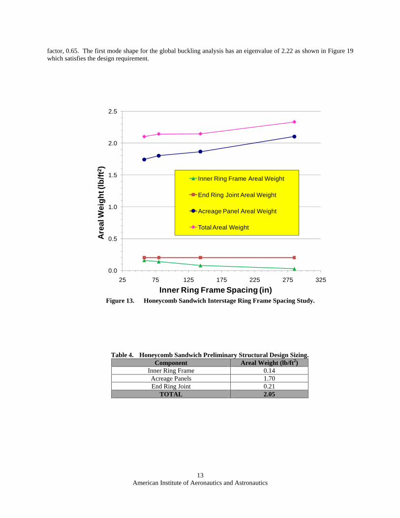
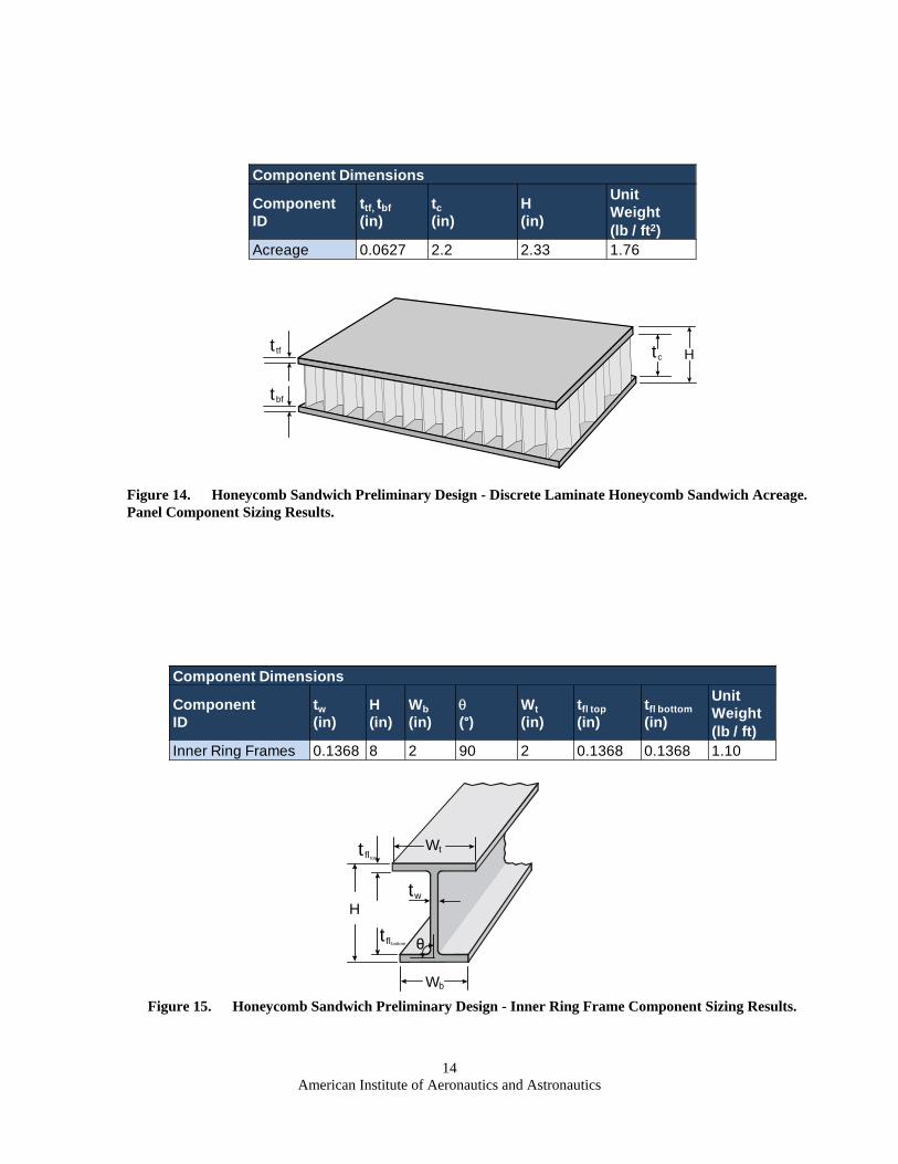
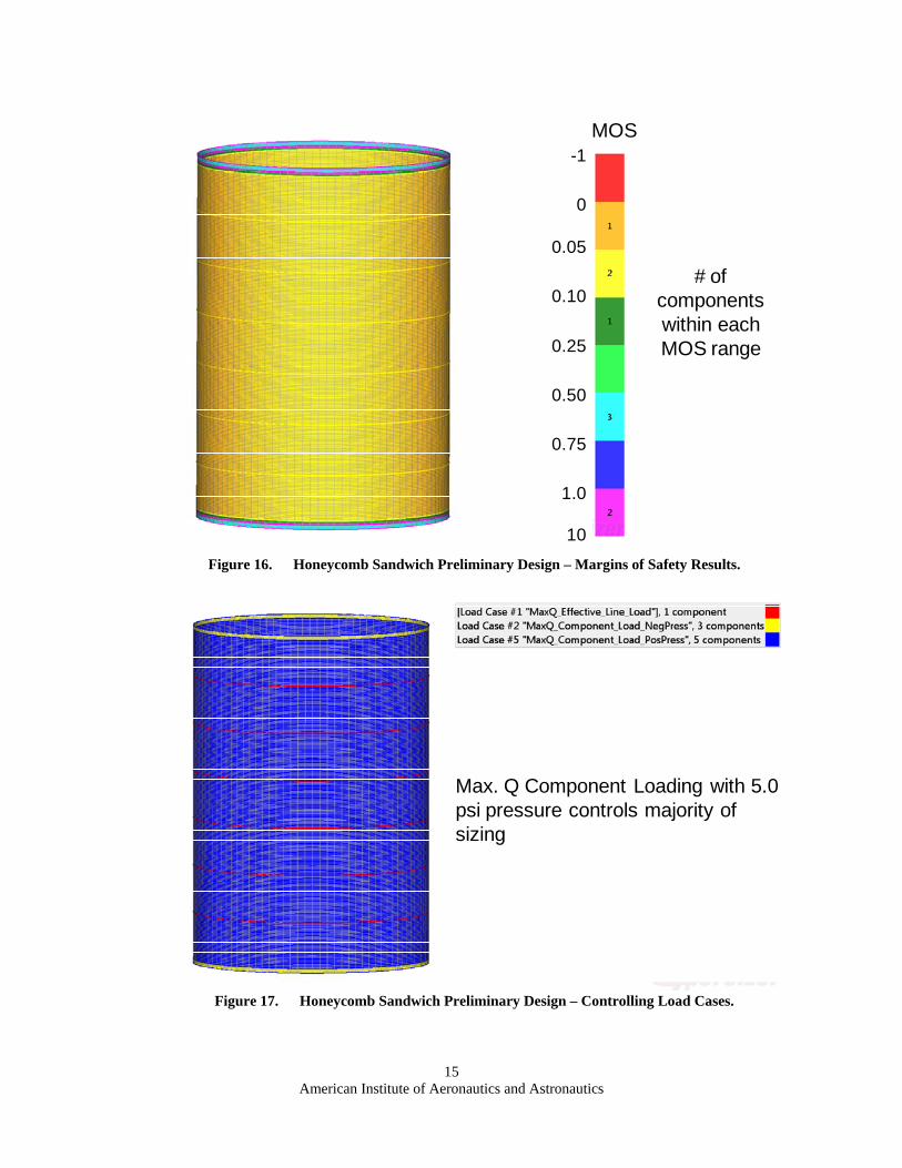
A trade study was performed to investigate the effect of varying the number of ring frames on the total structural weight of the Interstage. The trade study considered Interstage designs with ring frames evenly spaced from 57.5 inches (9 ring frames) to 285 inches (1 ring frame). For the sake of efficiency at this early stage in the work, multiple effective laminate layups (smeared properties) with different percentages of [0/±45/90]s plies were considered for the facesheets. The applied loads are defined in Table 2B. The results of the trade study are shown in Figure 13. The 57.5 inch ring frame spacing (9 ring frames) design was found to have the lowest total weight, but this concept was not considered for additional studies due to manufacturing considerations. The 80 inch (6 ring frames) and 143 inch (3 ring frames) ring frame spacing designs had total weights that were very close, but the 6 ring frame design was slightly lighter. Next, a HyperSizer analysis was performed to resize the 6 ring frame sandwich Interstage design using discrete laminates (ply-by-ply). The total areal weight of the Interstage decreased from 2.14 lb/ft2 to 2.05 lb/ft2 because the average panel weight decreased. A breakdown of the areal weights of the components of the discrete laminate sizing is shown in Table 4. The sizing results from the HyperSizer solution for the discrete laminate sizing for the acreage panels and the I-beam ring frames are shown in Figures 14 and 15. The discrete laminate for the sandwich facesheets had a [(+45/-45)/0/0/0/900.5]s layup, while the discrete laminate for the I-beam ring frames had a [(+45/-45)/03/90/03/90/02]s layup for the web and flanges. The depth of the sandwich core was 2.2 inches. The margins of safety results, the controlling load cases, and controlling failure analysis for the discrete laminate sizing are shown in Figures 16, 17, and 18, respectively. The margins of safety (MOS) in Fig. 16 are color-coded over the range of margin values where the numbers within the scale represent the number of components within each MOS range. The controlling load cases in Fig. 17 are colored-coded by which load case is the critical load case for each component. Similarly, the controlling failure analyses in Fig. 18 are color-coded by which failure analysis is the critical failure analysis for each component. The description of these plots is common throughout the reaminder of the paper. The lowest margin of safety occurred in the sandwich barrel component and had a margin of +0.02. The controlling load case for the majority of components was the component loading with 5.0 psi max. internal pressure load case as shown in Fig. 17, and the controlling failure analysis for the majority of components was composite strength as shown in Fig. 18. Next, a global buckling analysis was performed in Nastran to verify that the Interstage structure would satisfy a first mode buckling eigenvalue requirement of 2.15. This design requirement was determined from the ultimate load factor, 1.4, divided by the panel buckling knockdown
Figure 12. Hat-Stiffened Detailed HyperSizer Model Around Doors.
Solid Laminate
Ramp-down Hat
Longerons between ring frames (I-Beams)
Box Beam Frame around doors (4” x 4”, 0.2” Thick)
Hat Panels with thicker crowns and facesheets
Door Details
American Institute of Aeronautics and Astronautics
13
factor, 0.65. The first mode shape for the global buckling analysis has an eigenvalue of 2.22 as shown in Figure 19 which satisfies the design requirement.
Composite strength failure analysis (facesheet) controls majority of sizing
American Institute of Aeronautics and Astronautics
17
2. Hat-Stiffened Design A trade study was performed early in the preliminary design phase to investigate the effect of the number of ring
frames on the total structural weight of the Interstage, using the loads in Table 2A. Ring frame spacing varied from 30 inches (18 ring frames) to 75 inches (7 ring frames). The stiffness of the ring frames was originally set by the Shanley criteria (Ref. 14) to constrain buckling between the ring frames, but had to be adjusted as needed. The initial design was allowed to vary during sizing iterations to obtain a minimum eigenvalue of 2.15 on global buckling. Multiple effective laminate layups (smeared properties) with different percentages of [0/±45/90]s plies were again considered for the preliminary sizing. The results of the trade study are plotted in Figure 20. The study indicated that though a 52.5 inch ring frame spacing (11 ring frames) design had the lowest total areal weight, ring frame spacings from 45 to 75 inches could all be considered to be near optimal. It was determined that the ring frame spacing should not be lower than approximately 60 inches to account for the doors to be added in the detailed design study.
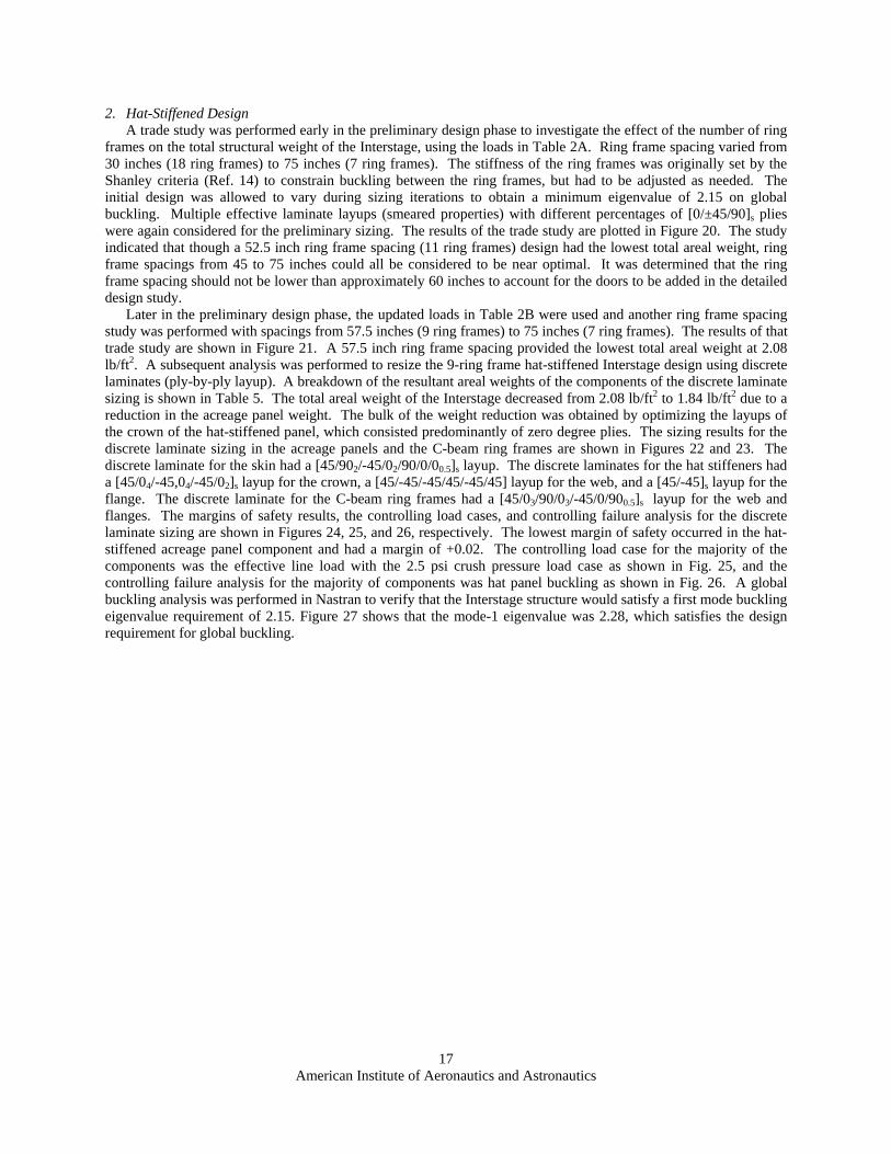
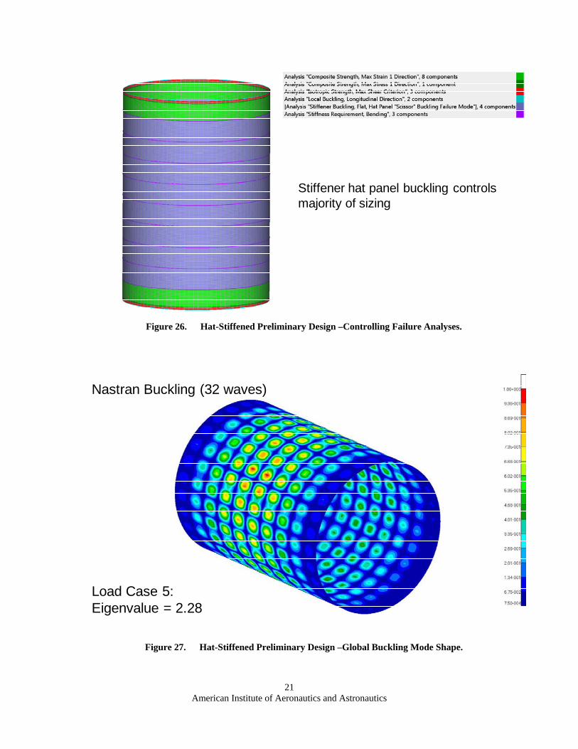
Later in the preliminary design phase, the updated loads in Table 2B were used and another ring frame spacing study was performed with spacings from 57.5 inches (9 ring frames) to 75 inches (7 ring frames). The results of that trade study are shown in Figure 21. A 57.5 inch ring frame spacing provided the lowest total areal weight at 2.08 lb/ft2. A subsequent analysis was performed to resize the 9-ring frame hat-stiffened Interstage design using discrete laminates (ply-by-ply layup). A breakdown of the resultant areal weights of the components of the discrete laminate sizing is shown in Table 5. The total areal weight of the Interstage decreased from 2.08 lb/ft2 to 1.84 lb/ft2 due to a reduction in the acreage panel weight. The bulk of the weight reduction was obtained by optimizing the layups of the crown of the hat-stiffened panel, which consisted predominantly of zero degree plies. The sizing results for the discrete laminate sizing in the acreage panels and the C-beam ring frames are shown in Figures 22 and 23. The discrete laminate for the skin had a [45/902/-45/02/90/0/00.5]s layup. The discrete laminates for the hat stiffeners had a [45/04/-45,04/-45/02]s layup for the crown, a [45/-45/-45/45/-45/45] layup for the web, and a [45/-45]s layup for the flange. The discrete laminate for the C-beam ring frames had a [45/03/90/03/-45/0/900.5]s layup for the web and flanges. The margins of safety results, the controlling load cases, and controlling failure analysis for the discrete laminate sizing are shown in Figures 24, 25, and 26, respectively. The lowest margin of safety occurred in the hat-stiffened acreage panel component and had a margin of +0.02. The controlling load case for the majority of the components was the effective line load with the 2.5 psi crush pressure load case as shown in Fig. 25, and the controlling failure analysis for the majority of components was hat panel buckling as shown in Fig. 26. A global buckling analysis was performed in Nastran to verify that the Interstage structure would satisfy a first mode buckling eigenvalue requirement of 2.15. Figure 27 shows that the mode-1 eigenvalue was 2.28, which satisfies the design requirement for global buckling.
American Institute of Aeronautics and Astronautics
18
Figure 21. Hat-Stiffened Panel Interstage Ring Frame Spacing Study 2.
0.0
0.5
1.0
1.5
2.0
2.5
50 55 60 65 70 75 80
Are
al W
eig
ht
(lb
/ft2
)
Ring Frame Spacing (in)
Inner Ring Frame Areal Weight
End Ring Joint Areal Weight
Aceage Panel Areal Weight
Total Areal Weight
Figure 20. Hat-Stiffened Panel Interstage Ring Frame Spacing Study 1.
0.0
0.5
1.0
1.5
2.0
2.5
3.0
25 50 75
Are
al W
eig
ht
(lb
/ft2
)
Ring Frame Spacing (in)
Inner Ring Frame Areal Weight
Aceage Panel Areal Weight
Total Acreage Areal Weight
American Institute of Aeronautics and Astronautics
Stiffener hat panel buckling controls majority of sizing
American Institute of Aeronautics and Astronautics
22
B. Detailed Sizing Results 1. Honeycomb Sandwich Design
Initial sizing analyses were performed on the 3-ring frame and 6-ring frame designs using effective laminate properties. The results of the initial sizing, shown in Table 6, indicated that the 6-ring frame design was lighter than the 3-ring frame design. Subsequent sizing was performed on the 6-ring frame honeycomb sandwich design using discrete laminates (ply-by-ply).
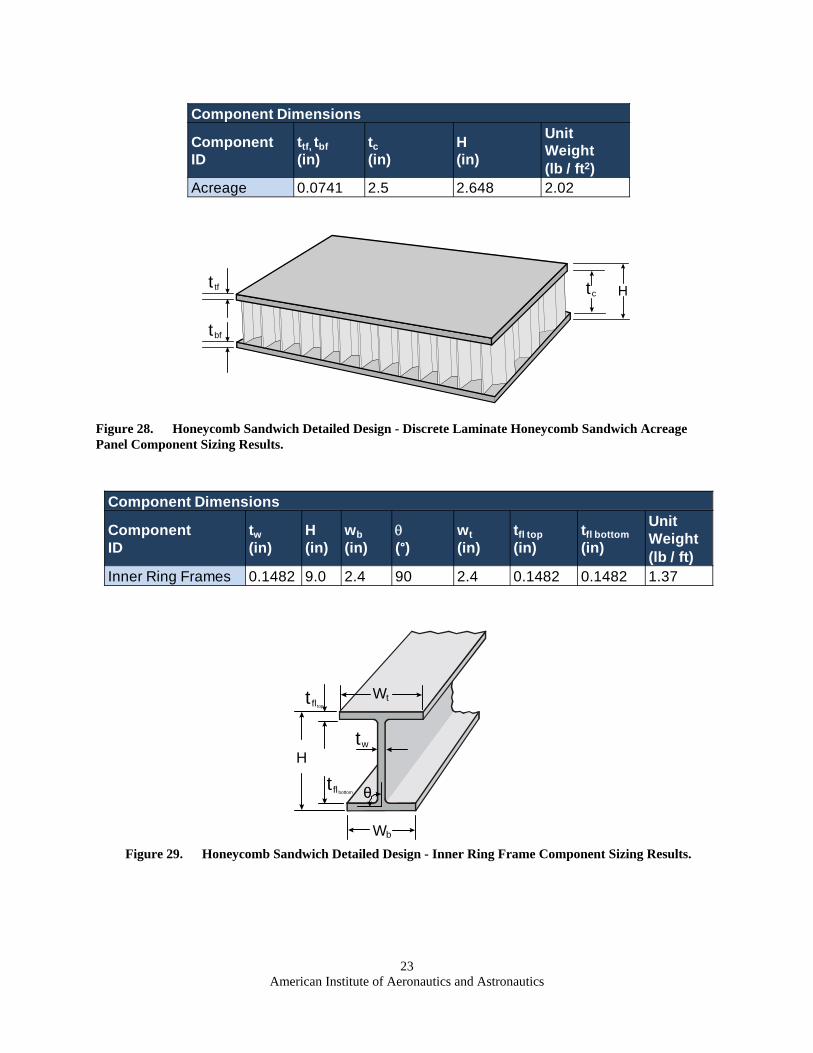
The final sizing results are shown in Table 7 with a breakdown of the areal weight components. The total areal weight of the Interstage decreased from 2.66 lb/ft2 to 2.45 lb/ft2 due to a reduction in the acreage panel weights. However, the areal weights were higher than those in the preliminary design because the uniform axial loads in the detailed design study were 17% higher than those in the preliminary design study. The sizing results from the discrete laminate analysis are shown in Figures 28 and 29. The discrete laminate for the sandwich facesheets had a [0/45/-45/0/90/0/00.5]s layup, while the discrete laminate for the C-beam ring frames had a [0/90/0/90/0/90/0/45/-45/0/90/02]s layup for the web and flanges. The depth of the sandwich core was 2.5 inches. The margins of safety results, the controlling load cases, and controlling failure analysis for the discrete laminate sizing are shown in Figures 30, 31, and 32, respectively. The lowest margin of safety occurred in one of the inner ring frame components and had a margin of +0.002. The controlling load case for the structural sizing was the effective line load with 2.5 psi crush pressure load case as shown in Fig. 31, and the controlling failure criterion for the majority of the acreage groups was panel buckling as shown in Fig. 32. The areas around the cutouts were controlled by strength failures. Finally, a global buckling analysis was performed in Nastran to verify that the Interstage structure would satisfy a first mode buckling eigenvalue requirement of 2.15. The first mode shape for the global buckling analysis, for the effective line load with 2.5 psi crush pressure load case, had an eigenvalue of 2.44 as shown in Figure 33. This satisfies the global buckling design requirement. Additional analyses are currently being performed to provide more details in the model to investigate the end ring joint and cutout (door, vents, and ECS) pad-up regions.
American Institute of Aeronautics and Astronautics
26
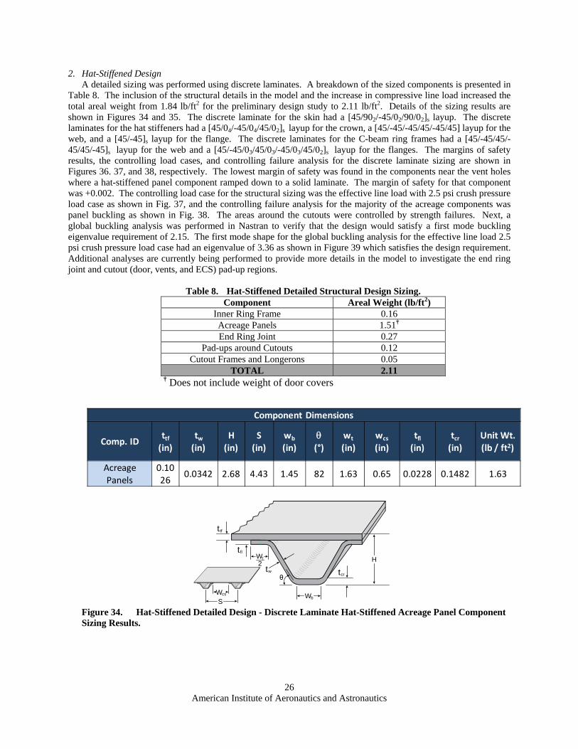
2. Hat-Stiffened Design A detailed sizing was performed using discrete laminates. A breakdown of the sized components is presented in
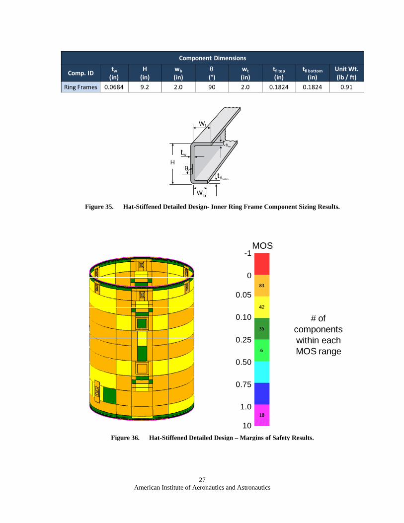
Table 8. The inclusion of the structural details in the model and the increase in compressive line load increased the total areal weight from 1.84 lb/ft2 for the preliminary design study to 2.11 lb/ft2. Details of the sizing results are shown in Figures 34 and 35. The discrete laminate for the skin had a [45/902/-45/02/90/02]s layup. The discrete laminates for the hat stiffeners had a [45/04/-45/04/45/02]s layup for the crown, a [45/-45/-45/45/-45/45] layup for the web, and a [45/-45]s layup for the flange. The discrete laminates for the C-beam ring frames had a [45/-45/45/-45/45/-45]s layup for the web and a [45/-45/03/45/03/-45/03/45/02]s layup for the flanges. The margins of safety results, the controlling load cases, and controlling failure analysis for the discrete laminate sizing are shown in Figures 36. 37, and 38, respectively. The lowest margin of safety was found in the components near the vent holes where a hat-stiffened panel component ramped down to a solid laminate. The margin of safety for that component was +0.002. The controlling load case for the structural sizing was the effective line load with 2.5 psi crush pressure load case as shown in Fig. 37, and the controlling failure analysis for the majority of the acreage components was panel buckling as shown in Fig. 38. The areas around the cutouts were controlled by strength failures. Next, a global buckling analysis was performed in Nastran to verify that the design would satisfy a first mode buckling eigenvalue requirement of 2.15. The first mode shape for the global buckling analysis for the effective line load 2.5 psi crush pressure load case had an eigenvalue of 3.36 as shown in Figure 39 which satisfies the design requirement. Additional analyses are currently being performed to provide more details in the model to investigate the end ring joint and cutout (door, vents, and ECS) pad-up regions.
American Institute of Aeronautics and Astronautics
29
3. Detailed Design Downselect
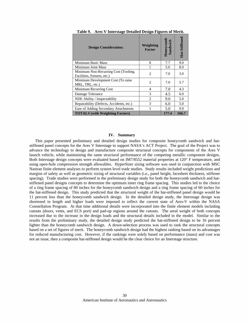
After the detailed sizing analyses were performed for the composite honeycomb sandwich and hat-stiffened Interstage design, a down-selection process was again performed to rank the designs by a set of figures of merit. The rankings for all design considerations were the same except for the basic mass ranking. The basic mass scores were determined from the total mass of only the two down-selected structural concepts from the detailed sizing results performed using HyperSizer. The score for the honeycomb sandwich basic mass was reduced by the percent difference in mass from the hat-stiffened design. Fastener weights were estimated for both designs and were considered in the joint mass scores. Again, the honeycomb sandwich had the higher total score due to its advantages in manufacturing cost. However, if the rankings were solely based on performance (mass) and cost was not an issue, then a composite hat-stiffened design would be the clear choice for the Interstage structure.
Figure 39. Hat-Stiffened Preliminary Design – Global Buckling Mode Shape.
Load Case 3: Eigenvalue: 3.36
American Institute of Aeronautics and Astronautics
30
IV. Summary
This paper presented preliminary and detailed design studies for composite honeycomb sandwich and hat-stiffened panel concepts for the Ares V Interstage to support NASA’s ACT Project. The goal of the Project was to advance the technology to design and manufacture composite structural concepts for components of the Ares V launch vehicle, while maintaining the same structural performance of the competing metallic component designs. Both Interstage design concepts were evaluated based on IM7/8552 material properties at 120° F temperature, and using open-hole compression strength allowables. HyperSizer sizing software was used in conjunction with MSC Nastran finite element analyses to perform system level trade studies. Study results included weight predictions and margins of safety as well as geometric sizing of structural variables (i.e., panel height, facesheet thickness, stiffener spacing). Trade studies were performed in the preliminary design study for both the honeycomb sandwich and hat-stiffened panel designs concepts to determine the optimum inner ring frame spacing. This studies led to the choice of a ring frame spacing of 80 inches for the honeycomb sandwich design and a ring frame spacing of 60 inches for the hat-stiffened design. This study predicted that the structural weight of the hat-stiffened panel design would be 11 percent less than the honeycomb sandwich design. In the detailed design study, the Interstage design was shortened in length and higher loads were imposed to reflect the current state of Ares-V within the NASA Constellation Program. At that time additional details were incorporated into the finite element models including cutouts (doors, vents, and ECS port) and pad-up regions around the cutouts. The areal weight of both concepts increased due to the increase in the design loads and the structural details included in the model. Similar to the results from the preliminary study, the detailed design study predicted the hat-stiffened design to be 16 percent lighter than the honeycomb sandwich design. A down-selection process was used to rank the structural concepts based on a set of figures of merit. The honeycomb sandwich design had the highest ranking based on its advantages for reduced manufacturing cost. However, if the rankings were solely based on performance (mass) and cost was not an issue, then a composite hat-stiffened design would be the clear choice for an Interstage structure.
Table 9. Ares V Interstage Detailed Design Figures of Merit.
Design Consideration: Weighting
Factor
Hon
eyco
mb
S
and
wic
h
Hat
-Sti
ffen
ed
Minimum Basic Mass 8 7.7 9.0 Minimum Joint Mass 1 5.0 8.0 Minimum Non-Recurring Cost (Tooling, Facilities, fixtures, etc.)
2 7.0 3.0
Minimum Development Cost (To raise MRL, TRL, etc.)
American Institute of Aeronautics and Astronautics
31
References
1Bednarcyk, B. A., Arnold, S. M., and Hopkins, D. A., “Design of Fiber Reinforced Foam Sandwich Panels for Large Ares V
Structural Applications,” AIAA/ASME/ASCE/AHS/ASC Structures, Structural Dynamics, and Materials Conference, Orlando, Florida, April, 2010.
2Zalewski, B., and Dial, W., “Preliminary Structural Sizing of the Hat-Stiffened, Corrugated, and Fluted Panel Concepts for ARES V Vehicle Shroud,” AIAA/ASME/ASCE/AHS/ASC Structures, Structural Dynamics, and Materials Conference, Orlando, Florida, April, 2010.
3Zalewski, B., and Bednarcyk, B. A. “ACT Payload Shroud Structural Concept Analysis and Optimization,” NASA/TM-2010-216942, December 2010.
4Thomas, S., et al., “Advanced Composites Technology Structural Concepts Ares V Core Intertank Phase I”, NASA/TM (to be published).
5Thomas, S., et al., “Advanced Composites Technology Structural Concepts Ares V Core Intertank Phase II”, NASA/TM (to be published).
6WebCore Technologies, Inc., Miamisburg, OH, http://www.webcoreonline.com/. 7Li, V. and Velicki, A., “Advanced PRSEUS Structural Concept Design and Optimization,” AIAA/ASME/ASCE/AHS/ASC
Structures, Structural Dynamics, and Materials Conference, Palm Springs, CA, 2008. 8HyperSizer Structural Sizing Software, Collier Research Corp., Ver. 5.9.2, Hampton, VA, http://www.hypersizer.com, 2010. 9MSC Nastran, MSC Software Corporation, Ver. 2008r1, Santa Ana, CA, http://www.mscsoftware.com, 2008. 10Collier, C., Ainsworth, J., Yarrington, P., and Lucking, R., “Ares V Interstage Composite Panel Concept and Ringframe
Spacing Trade Studies,” AIAA/ASME/ASCE/AHS/ASC Structures, Structural Dynamics, and Materials Conference, Orlando, Florida, April, 2010.
11MSC Patran, MSC Software Corporation, Ver. 2008r1, Santa Ana, CA, http://www.mscsoftware.com, 2008. 12NASA-STD-5001A, “Structural Design and Test Factors of Safety for Spaceflight Hardware,” NASA Technical Standards
Program, August, 2008. 13Hexcel Corporation, Stamford, CT, http://www.hexcel.com/. 14Niu, Michael C. Y., Airframe Structural Design, 5th ed., Conmilt Press LTD., Hong Kong, 1990, Chap. 11.