7
Structural design of mechanically compensated zoom lenses by evolutionary programming Sourav Pal Lakshminarayan Hazra

Structural design of mechanicallycompensated zoom lenses byevolutionary programming
Sourav PalLakshminarayan Hazra

Structural design of mechanically compensated zoomlenses by evolutionary programming
Sourav PalLakshminarayan HazraUniversity of CalcuttaDepartment of Applied Optics and Photonics92 Acharya Prafulla Chandra RoadKolkata, IndiaE-mail: [email protected]
Abstract. This paper reports our investigations on the design of globally orquasi-globally optimal structures for three-component and four-componentmechanically compensated zoom lenses. This is accomplished by imple-mentation of a global optimization technique based on evolutionaryprogramming. The technique searches optimal structures in the configura-tion space formed by the specific design variables: powers of individualcomponents and the intercomponent separations. Any requirements forsystem length and Petzval curvature of the zoom lens can be incorporatedin the search for optimal solutions. Illustrative numerical results of ourinvestigations on four regular types of zoom systems, as classified byTanaka, are presented. © 2012 Society of Photo-Optical Instrumentation Engineers(SPIE). [DOI: 10.1117/1.OE.51.6.063001]
Subject terms: zoom lenses; optical design; lenses; geometric optics; geneticalgorithm; evolutionary programming.
Paper 120234 received Feb. 21, 2012; revised manuscript received Apr. 6, 2012;accepted for publication Apr. 6, 2012; published online Jun. 5, 2012.
1 IntroductionA mechanically compensated zoom lens1–10 maintains asharp image over a fixed image plane during the continuousvariation of magnification in image over the zoom range. Ingeneral, the magnification of the zoom system is changed byaxially shifting a component, called the variator, but thischange in magnification is always accompanied by a blurringof image due to shift of the image plane. The final image isthen restored to the original image plane by moving anotherlens component, called the compensator. This restoration ofthe final image usually demands a nonlinear movement ofthe compensator with respect to the variator. The key pro-blem of structural design of a mechanically compensatedzoom lens is determination of the powers of the constituentlens components and the intercomponent separations thatlead to convenient motions of its moving components.Early works on varifocal lenses may be traced back to theattempts by Barlow in 1834,11 Dallmeyer,12 Allen,13
Holst,14 Warmisham and Mitchell,15 and Gramatzki.16 Tothe best of our knowledge, Capstaff et al.17 reported avarifocal system which may be considered as a precursorof the mechanically compensated zoom lens. Since then,many mechanically compensated zoom lens structures havebeen proposed by Hopkins,18,19 Angénieux,20 Yamaji,21,22
Besenmatter,23 Betensky,24 Tanaka,25,26 Neil and Betensky,27
and Fang et al.,28 among others.Many semi-analytical methods have been proposed for
designing mechanically compensated zoom structures.Hopkins29 demonstrated an analytical method for designinga symmetrical zoom lens. In his seminal article on the designof zoom lenses, Yamaji3 classified mechanically compen-sated zoom lenses in five basic structures. In a series ofarticles, Tanaka30–33 presented analytical techniques basedon Gaussian brackets, for structural design of mechanicallycompensated zoom lenses. Kryszczyński34 proposed a
method of analytical design for four-component mechani-cally compensated zoom lenses. Oskotsky35 used grapho-analytical method, while Tao36 used differential equationsfor designing thin lens structures of mechanically compen-sated zoom lenses. Park and Shannon37 used lens modules todesign zoom lens structures. These methods were developedwith different objectives in view, and often they have pro-vided solutions as sought for. Nevertheless, practical successleading to good designs depends to a large extent on choiceof the starting point. Recently Cheng, Wang, Hao andSasian38 reported a technique to overcome this weaknessof previous design methods. Their method selects the beststarting point for the optimization of zoom structure froma database of about 2000 zoom lenses. Although thousandsof lens design forms are readily available in lens data banksand can provide quick fix solution to most practical pro-blems, blindfold adaptation of these forms holds no guaran-tee for ensuring globally or quasi-globally optimal solutionsfor the problem at hand.
This paper demonstrates a technique for ab initio synth-esis of thin lens structures of mechanically compensatedzoom lenses diagrammed in Fig. 1. The quasi-global searchtechnique, presented here for structural design of mechani-cally compensated zoom lenses, uses an implementation ofgenetic algorithm (GA) based on evolutionary programming.It searches for a quasi-globally optimum solution in thehyperspace, formed by the design variables, namely powersof the individual components and intercomponent separa-tions. The search for optimal solutions can be carried outto satisfy the desired requirements for system length andPetzval curvature of the zoom lens, if any. In our approach,preferred operations of the zoom lens components to facil-itate reduction in complexity of their axial movement canalso be accommodated by introduction of suitable penaltychecks. Use of evolutionary programming in search for opti-mal structures of optically compensated zoom and linearlycompensated zoom lenses have already been reported inour previous publications.39–42 Implementation of the same0091-3286/2012/$25.00 © 2012 SPIE
Optical Engineering 063001-1 June 2012/Vol. 51(6)
Optical Engineering 51(6), 063001 (June 2012)
to the case of mechanically compensated zoom lenses callsfor major modifications, which are reported in this study.
2 Evolutionary ProgrammingIn the thin lens design stage, powers of the individualcomponents and their separations are the design variables.Therefore, optimization of the thin lens structure of amechanically compensated zoom lens involves finding outpoints in the constrained hyperspace formed by these designvariables, that lead to thin lens structures with characteristicssame as or very close to the required zoom lens.
2.1 Design Variables and Degrees of Freedom
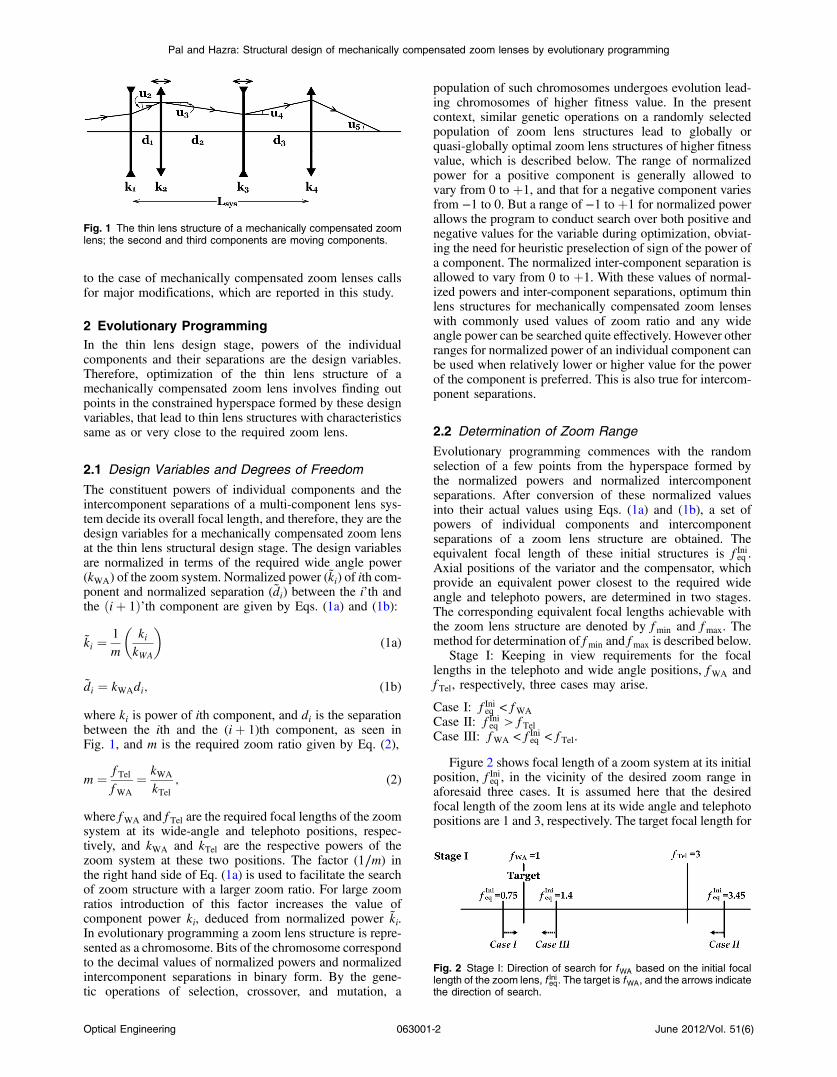
The constituent powers of individual components and theintercomponent separations of a multi-component lens sys-tem decide its overall focal length, and therefore, they are thedesign variables for a mechanically compensated zoom lensat the thin lens structural design stage. The design variablesare normalized in terms of the required wide angle power(kWA) of the zoom system. Normalized power (k̃i) of ith com-ponent and normalized separation (d̃i) between the i’th andthe ðiþ 1Þ’th component are given by Eqs. (1a) and (1b):
k̃i ¼1
m
�kikWA
�(1a)
d̃i ¼ kWAdi; (1b)
where ki is power of ith component, and di is the separationbetween the ith and the (iþ 1)th component, as seen inFig. 1, and m is the required zoom ratio given by Eq. (2),
m ¼ f TelfWA
¼ kWA
kTel; (2)
where fWA and f Tel are the required focal lengths of the zoomsystem at its wide-angle and telephoto positions, respec-tively, and kWA and kTel are the respective powers of thezoom system at these two positions. The factor (1∕m) inthe right hand side of Eq. (1a) is used to facilitate the searchof zoom structure with a larger zoom ratio. For large zoomratios introduction of this factor increases the value ofcomponent power ki, deduced from normalized power k̃i.In evolutionary programming a zoom lens structure is repre-sented as a chromosome. Bits of the chromosome correspondto the decimal values of normalized powers and normalizedintercomponent separations in binary form. By the gene-tic operations of selection, crossover, and mutation, a
population of such chromosomes undergoes evolution lead-ing chromosomes of higher fitness value. In the presentcontext, similar genetic operations on a randomly selectedpopulation of zoom lens structures lead to globally orquasi-globally optimal zoom lens structures of higher fitnessvalue, which is described below. The range of normalizedpower for a positive component is generally allowed tovary from 0 to þ1, and that for a negative component variesfrom −1 to 0. But a range of −1 to þ1 for normalized powerallows the program to conduct search over both positive andnegative values for the variable during optimization, obviat-ing the need for heuristic preselection of sign of the power ofa component. The normalized inter-component separation isallowed to vary from 0 to þ1. With these values of normal-ized powers and inter-component separations, optimum thinlens structures for mechanically compensated zoom lenseswith commonly used values of zoom ratio and any wideangle power can be searched quite effectively. However otherranges for normalized power of an individual component canbe used when relatively lower or higher value for the powerof the component is preferred. This is also true for intercom-ponent separations.
2.2 Determination of Zoom Range
Evolutionary programming commences with the randomselection of a few points from the hyperspace formed bythe normalized powers and normalized intercomponentseparations. After conversion of these normalized valuesinto their actual values using Eqs. (1a) and (1b), a set ofpowers of individual components and intercomponentseparations of a zoom lens structure are obtained. Theequivalent focal length of these initial structures is f Inieq .Axial positions of the variator and the compensator, whichprovide an equivalent power closest to the required wideangle and telephoto powers, are determined in two stages.The corresponding equivalent focal lengths achievable withthe zoom lens structure are denoted by fmin and fmax. Themethod for determination of fmin and fmax is described below.
Stage I: Keeping in view requirements for the focallengths in the telephoto and wide angle positions, fWA andf Tel, respectively, three cases may arise.
Case I: f Inieq < fWA
Case II: f Inieq > f TelCase III: fWA < f Inieq < f Tel.
Figure 2 shows focal length of a zoom system at its initialposition, f Inieq , in the vicinity of the desired zoom range inaforesaid three cases. It is assumed here that the desiredfocal length of the zoom lens at its wide angle and telephotopositions are 1 and 3, respectively. The target focal length for
Fig. 1 The thin lens structure of a mechanically compensated zoomlens; the second and third components are moving components.
Fig. 2 Stage I: Direction of search for fWA based on the initial focallength of the zoom lens, f Inieq. The target is fWA, and the arrows indicatethe direction of search.
Optical Engineering 063001-2 June 2012/Vol. 51(6)
Pal and Hazra: Structural design of mechanically compensated zoom lenses by evolutionary programming
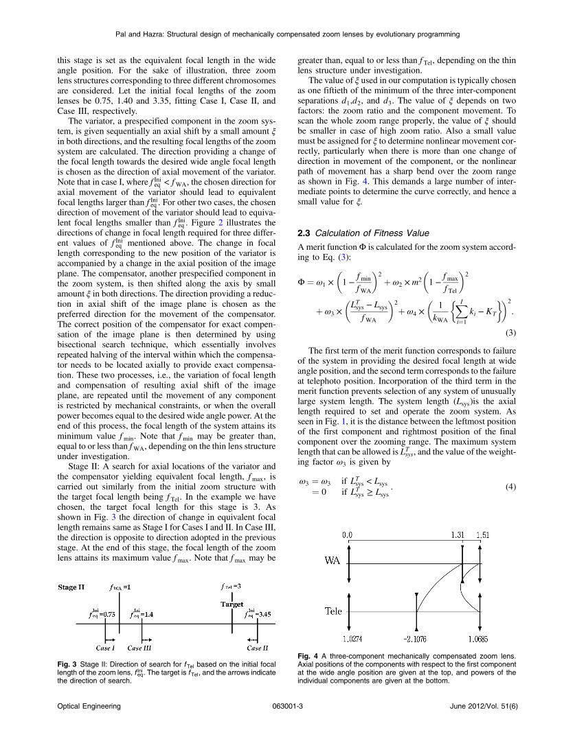
this stage is set as the equivalent focal length in the wideangle position. For the sake of illustration, three zoomlens structures corresponding to three different chromosomesare considered. Let the initial focal lengths of the zoomlenses be 0.75, 1.40 and 3.35, fitting Case I, Case II, andCase III, respectively.
The variator, a prespecified component in the zoom sys-tem, is given sequentially an axial shift by a small amount ξin both directions, and the resulting focal lengths of the zoomsystem are calculated. The direction providing a change ofthe focal length towards the desired wide angle focal lengthis chosen as the direction of axial movement of the variator.Note that in case I, where f Inieq < fWA, the chosen direction foraxial movement of the variator should lead to equivalentfocal lengths larger than f Inieq . For other two cases, the chosendirection of movement of the variator should lead to equiva-lent focal lengths smaller than f Inieq . Figure 2 illustrates thedirections of change in focal length required for three differ-ent values of f Inieq mentioned above. The change in focallength corresponding to the new position of the variator isaccompanied by a change in the axial position of the imageplane. The compensator, another prespecified component inthe zoom system, is then shifted along the axis by smallamount ξ in both directions. The direction providing a reduc-tion in axial shift of the image plane is chosen as thepreferred direction for the movement of the compensator.The correct position of the compensator for exact compen-sation of the image plane is then determined by usingbisectional search technique, which essentially involvesrepeated halving of the interval within which the compensa-tor needs to be located axially to provide exact compensa-tion. These two processes, i.e., the variation of focal lengthand compensation of resulting axial shift of the imageplane, are repeated until the movement of any componentis restricted by mechanical constraints, or when the overallpower becomes equal to the desired wide angle power. At theend of this process, the focal length of the system attains itsminimum value fmin. Note that fmin may be greater than,equal to or less than fWA, depending on the thin lens structureunder investigation.
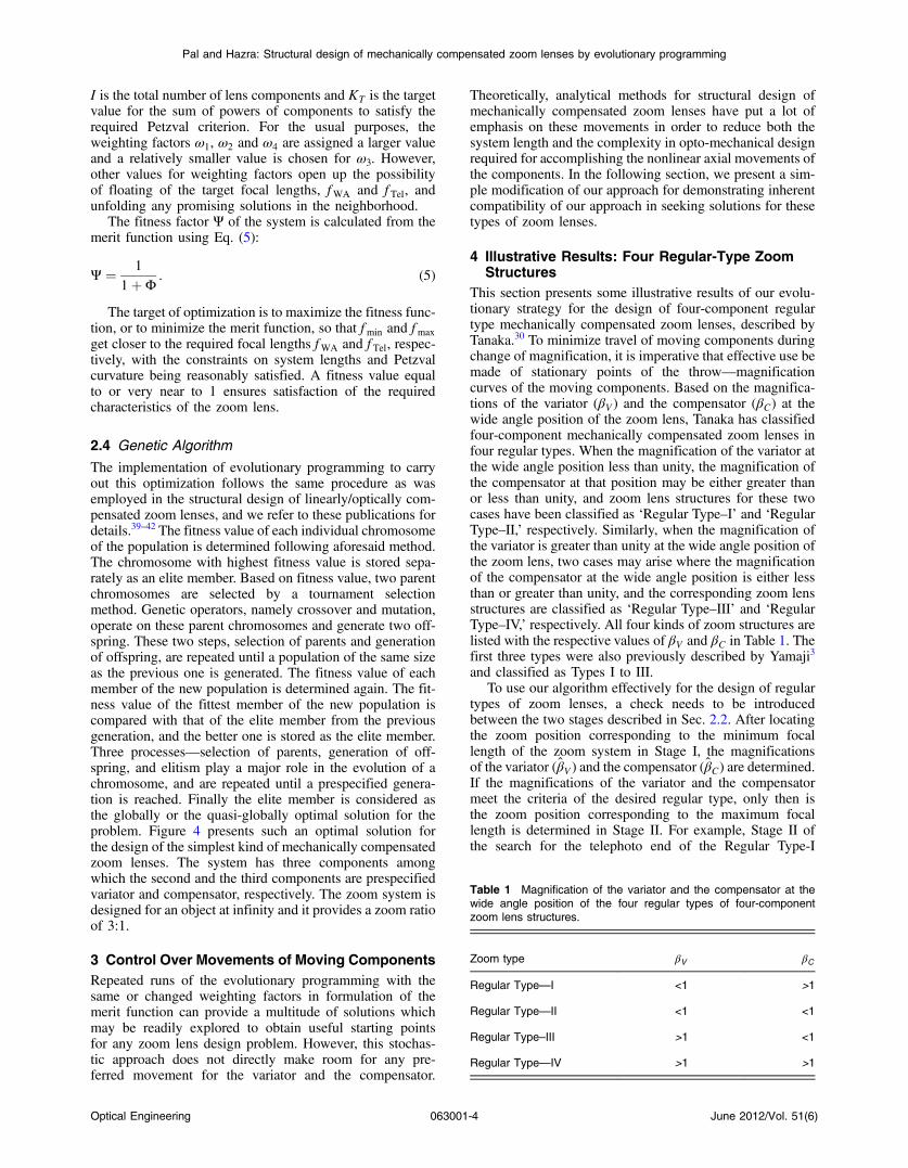
Stage II: A search for axial locations of the variator andthe compensator yielding equivalent focal length, fmax, iscarried out similarly from the initial zoom structure withthe target focal length being f Tel. In the example we havechosen, the target focal length for this stage is 3. Asshown in Fig. 3 the direction of change in equivalent focallength remains same as Stage I for Cases I and II. In Case III,the direction is opposite to direction adopted in the previousstage. At the end of this stage, the focal length of the zoomlens attains its maximum value fmax. Note that fmax may be
greater than, equal to or less than f Tel, depending on the thinlens structure under investigation.
The value of ξ used in our computation is typically chosenas one fiftieth of the minimum of the three inter-componentseparations d1,d2, and d3. The value of ξ depends on twofactors: the zoom ratio and the component movement. Toscan the whole zoom range properly, the value of ξ shouldbe smaller in case of high zoom ratio. Also a small valuemust be assigned for ξ to determine nonlinear movement cor-rectly, particularly when there is more than one change ofdirection in movement of the component, or the nonlinearpath of movement has a sharp bend over the zoom rangeas shown in Fig. 4. This demands a large number of inter-mediate points to determine the curve correctly, and hence asmall value for ξ.
2.3 Calculation of Fitness Value
Amerit functionΦ is calculated for the zoom system accord-ing to Eq. (3):
Φ ¼ ω1 ×�1−
fmin
fWA
�2
þω2 ×m2
�1−
fmax
f Tel
�2
þω3 ×�LTsys − Lsys
fWA
�2
þω4 ×�
1
kWA
�XI
i¼1
ki − KT
��2
.
(3)
The first term of the merit function corresponds to failureof the system in providing the desired focal length at wideangle position, and the second term corresponds to the failureat telephoto position. Incorporation of the third term in themerit function prevents selection of any system of unusuallylarge system length. The system length (Lsys)is the axiallength required to set and operate the zoom system. Asseen in Fig. 1, it is the distance between the leftmost positionof the first component and rightmost position of the finalcomponent over the zooming range. The maximum systemlength that can be allowed is LTsys, and the value of the weight-ing factor ω3 is given by
ω3 ¼ ω3 if LTsys < Lsys¼ 0 if LTsys ≥ Lsys
. (4)
Fig. 3 Stage II: Direction of search for f Tel based on the initial focallength of the zoom lens, f Inieq. The target is f Tel, and the arrows indicatethe direction of search.
Fig. 4 A three-component mechanically compensated zoom lens.Axial positions of the components with respect to the first componentat the wide angle position are given at the top, and powers of theindividual components are given at the bottom.
Optical Engineering 063001-3 June 2012/Vol. 51(6)
Pal and Hazra: Structural design of mechanically compensated zoom lenses by evolutionary programming
I is the total number of lens components and KT is the targetvalue for the sum of powers of components to satisfy therequired Petzval criterion. For the usual purposes, theweighting factors ω1, ω2 and ω4 are assigned a larger valueand a relatively smaller value is chosen for ω3. However,other values for weighting factors open up the possibilityof floating of the target focal lengths, fWA and f Tel, andunfolding any promising solutions in the neighborhood.
The fitness factor Ψ of the system is calculated from themerit function using Eq. (5):
Ψ ¼ 1
1þΦ. (5)
The target of optimization is to maximize the fitness func-tion, or to minimize the merit function, so that fmin and fmax
get closer to the required focal lengths fWA and f Tel, respec-tively, with the constraints on system lengths and Petzvalcurvature being reasonably satisfied. A fitness value equalto or very near to 1 ensures satisfaction of the requiredcharacteristics of the zoom lens.
2.4 Genetic Algorithm
The implementation of evolutionary programming to carryout this optimization follows the same procedure as wasemployed in the structural design of linearly/optically com-pensated zoom lenses, and we refer to these publications fordetails.39–42 The fitness value of each individual chromosomeof the population is determined following aforesaid method.The chromosome with highest fitness value is stored sepa-rately as an elite member. Based on fitness value, two parentchromosomes are selected by a tournament selectionmethod. Genetic operators, namely crossover and mutation,operate on these parent chromosomes and generate two off-spring. These two steps, selection of parents and generationof offspring, are repeated until a population of the same sizeas the previous one is generated. The fitness value of eachmember of the new population is determined again. The fit-ness value of the fittest member of the new population iscompared with that of the elite member from the previousgeneration, and the better one is stored as the elite member.Three processes—selection of parents, generation of off-spring, and elitism play a major role in the evolution of achromosome, and are repeated until a prespecified genera-tion is reached. Finally the elite member is considered asthe globally or the quasi-globally optimal solution for theproblem. Figure 4 presents such an optimal solution forthe design of the simplest kind of mechanically compensatedzoom lenses. The system has three components amongwhich the second and the third components are prespecifiedvariator and compensator, respectively. The zoom system isdesigned for an object at infinity and it provides a zoom ratioof 3:1.
3 Control Over Movements of Moving ComponentsRepeated runs of the evolutionary programming with thesame or changed weighting factors in formulation of themerit function can provide a multitude of solutions whichmay be readily explored to obtain useful starting pointsfor any zoom lens design problem. However, this stochas-tic approach does not directly make room for any pre-ferred movement for the variator and the compensator.
Theoretically, analytical methods for structural design ofmechanically compensated zoom lenses have put a lot ofemphasis on these movements in order to reduce both thesystem length and the complexity in opto-mechanical designrequired for accomplishing the nonlinear axial movements ofthe components. In the following section, we present a sim-ple modification of our approach for demonstrating inherentcompatibility of our approach in seeking solutions for thesetypes of zoom lenses.
4 Illustrative Results: Four Regular-Type ZoomStructures
This section presents some illustrative results of our evolu-tionary strategy for the design of four-component regulartype mechanically compensated zoom lenses, described byTanaka.30 To minimize travel of moving components duringchange of magnification, it is imperative that effective use bemade of stationary points of the throw—magnificationcurves of the moving components. Based on the magnifica-tions of the variator (βV ) and the compensator (βC) at thewide angle position of the zoom lens, Tanaka has classifiedfour-component mechanically compensated zoom lenses infour regular types. When the magnification of the variator atthe wide angle position less than unity, the magnification ofthe compensator at that position may be either greater thanor less than unity, and zoom lens structures for these twocases have been classified as ‘Regular Type–I’ and ‘RegularType–II,’ respectively. Similarly, when the magnification ofthe variator is greater than unity at the wide angle position ofthe zoom lens, two cases may arise where the magnificationof the compensator at the wide angle position is either lessthan or greater than unity, and the corresponding zoom lensstructures are classified as ‘Regular Type–III’ and ‘RegularType–IV,’ respectively. All four kinds of zoom structures arelisted with the respective values of βV and βC in Table 1. Thefirst three types were also previously described by Yamaji3
and classified as Types I to III.To use our algorithm effectively for the design of regular
types of zoom lenses, a check needs to be introducedbetween the two stages described in Sec. 2.2. After locatingthe zoom position corresponding to the minimum focallength of the zoom system in Stage I, the magnificationsof the variator (β̂V ) and the compensator (β̂C) are determined.If the magnifications of the variator and the compensatormeet the criteria of the desired regular type, only then isthe zoom position corresponding to the maximum focallength is determined in Stage II. For example, Stage II ofthe search for the telephoto end of the Regular Type-I
Table 1 Magnification of the variator and the compensator at thewide angle position of the four regular types of four-componentzoom lens structures.
Zoom type βV βC
Regular Type—I <1 >1
Regular Type—II <1 <1
Regular Type–III >1 <1
Regular Type—IV >1 >1
Optical Engineering 063001-4 June 2012/Vol. 51(6)
Pal and Hazra: Structural design of mechanically compensated zoom lenses by evolutionary programming

zoom lens will be executed if and only if β̂V < 1 and β̂C > 1.For other values of β̂V and β̂C the fitness value is set to zero(Ψ ¼ 0). Table 2 presents the required conditions for execu-tion of Stage II of the determination of Gaussian character-istics in the case of each of the four regular types of zoomlenses. Depending upon the values of β̂V and β̂C, four casesmay arise which are listed in Table 2. For each type of zoomlens, Stage II is executed for one favorable combination ofβ̂V and β̂C. For rest of the combinations of β̂V and β̂C, thefitness value is set to zero making the corresponding chro-mosome unfit and it will never be selected as an elite memberor for the final result.
Some results of our investigations for the design of thefour regular types of mechanically compensated zoom lensesare presented in Figs. 5–8. Each zoom lens structure isdesigned for zoom ratio of 5:1. The wide angle power ofeach of these zoom lenses is 1. The powers of individualcomponents are written under each one. The locations ofeach component at the wide angle position of the zoomlens is measured with respect to the first component ofthe lens system, and are given at the top of each figure.Movements of the variator and the compensator are drawnwith respect to a regular change in focal length of thezoom system or, in other words, the power of the zoomsystem varies linearly in the vertical direction in each figure.The second and the third components are the pre-specifiedvariator and compensator for the zoom lens, respectively.
5 Concluding RemarksEach of the five zoom systems presented in Figs. 4–8 is onepotential solution for the specified zoom range. Multiplesolutions in each case may be obtained by repeated runsof the optimization algorithm. The usefulness of a solutionfor a specific practical application needs to be based onaberrational considerations. Although a precaution againstthe Petzval sum has been taken, reduction of other Seidelaberration coefficients is possible with the aberration correc-tion methods described by Yamaji,3 Hopkins,43 and recentlyby Mikš.44 Nevertheless, a preliminary feasibility study onthe likelihood of nonoccurrence of large aberrations canbe carried out by setting a minimum permissible D-Number,
Table 2 Mode of implementation of Stage II for the four regular typesof zoom lenses.
Desiredzoomlens type
β̂V < 1 β̂V > 1
β̂C > 1 β̂C < 1 β̂C < 1 β̂C > 1
Type—I Go forStage II
Ψ ¼ 0 Ψ ¼ 0 Ψ ¼ 0
Type—II Ψ ¼ 0 Go forStage II
Ψ ¼ 0 Ψ ¼ 0
Type–III Ψ ¼ 0 Ψ ¼ 0 Go forStage II
0
Type—IV Ψ ¼ 0 Ψ ¼ 0 Ψ ¼ 0 Go forStage II
Fig. 5 A Regular Type–I four-component mechanically compensatedzoom lens. Axial position and power are given along the top andbottom, respectively, as in Fig. 4.
Fig. 6 ARegular Type–II four-component mechanically compensatedzoom lens. Axial position and power are given along the top andbottom, respectively, as in Fig. 4.
Fig. 7 A Regular Type–III four-component mechanically compen-sated zoom lens. Axial position and power are given along the topand bottom, respectively, as in Fig. 4.
Fig. 8 A Regular Type–IV four-component mechanically compen-sated zoom lens. Axial position and power are given along the topand bottom, respectively, as in Fig. 4.
Optical Engineering 063001-5 June 2012/Vol. 51(6)
Pal and Hazra: Structural design of mechanically compensated zoom lenses by evolutionary programming
also specified as D# for each of the components.39 The valueof D# for ith component is given by Eq. (6),
Di# ¼
1
ki½jhij þ jh̄ij�; (6)
where ki is the power of ith component and jhij and jh̄ij arethe largest absolute heights over zoom range of the paraxialmarginal ray and the paraxial pupil ray on the ith component,respectively. Tracing of these rays calls for knowledge ofthe size and the location of the aperture stop, which isusually dictated by photometric considerations and systemconstraints.
Among the four regular types of zoom lenses mentionedby Tanaka,30 the first three belongs to the first three types ofzoom structures classified by Yamaji.3 To the best of ourknowledge, this paper presents numerical data for a zoomlens of the Regular Type–IV for the first time.
Finally, the illustrative results presented in the last sectionshow the convenient amenability of our optimization techni-que for the design of three-component and four-componentmechanically compensated zoom lens structures. This sto-chastic approach holds potential for unfolding new types ofzoom lens structures, and we intend to report our investiga-tions on the same in near future.
References
1. D. Clark, Zoom lenses, Adam Hilger, London (1973).2. R. Kingslake, “The development of the zoom lens,” J. SMPTE
69(August), 534–544 (1960).3. K. Yamaji, “Design of zoom lenses,” in Progress in Optics, E. Wolf, ed.,
Vol. VI, 107–170, North-Holland, Amsterdam (1967).4. A. Cox, “Zoom lens design,” Proc. SPIE 4487, 1–11 (2001).5. T. Uzawa, “Zoom lens system,” U.S. Pat. 5270863 (1993).6. N. Kodama, “Zoom lens,” U.S. Pat. 5835272 (1998).7. T. Tanaka, “Zoom lens and imaging apparatus,”U.S. Pat. 2010/0289926
A1 (2010).8. N. Miyazawa, “Zoom lens system and camera equipped with the same,”
U.S. Pat. 7835084 B2 (2010).9. K. Yamada, “Zoom eyepiece lens system,” U.S. Pat. 7903343 B2
(2011).10. T. Nakamura, “Zoom lens system and image pickup apparatus including
the same,” U.S. Pat. 2011/0038056 A1 (2011).11. R. Kingslake and R. Barry Jhonson, Lens Design Fundamentals, SPIE
Press, Washington, USA, pp. 397 (2010).12. T. R. Dallmeyer, Telephotography, Heinemann, London (1899).13. C. C. Allen, “Optical objective,” U.S. Pat. 696788 (1901).14. L. J. R. Holst, “Telephotographic apparatus,” U.S. Pat. 1138217 (1914).15. A. Warmisham and R. F. Mitchell, “The Bell and Howell Cook Varo
lens,” J. SMPTE 19(4), 329–339 (1932).16. H. J. Gramatzki, “Der Transfokator,” British Pat. 449434 (1936).17. J. G. Capstaff and O. E. Miller, “Photographic objective,” U.S. Pat.
2165341 (1939).18. H. H. Hopkins, “Variable magnification optical system,” U.S. Pat.
2566889 (1947).19. H. H. Hopkins, “Variable magnification optical systems,” U.S. Pat.
2471155 (1956).20. P. Angénieux, “Variable focal-length objectives,” U.S. Pat. 2847907
(1958).21. K. Yamaji, “Zoom lens system,” U. S. Pat. 3027805 (1962).22. K. Yamaji, “Zoom lens system,” U.S. Pat. 3074318 (1963).23. W. Besenmatter, “Basic lens assembly for series of zoom objectives of
different varifocal ratios,” U.S. Pat. 4066340 (1978).24. E. I. Betensky, “Compact zoom lens with high zoom ratio,” U.S. Pat.
4991943 (1991).25. K. Tanaka, “Zoom lens,” U. S. Pat. 4281906 (1981).26. K. Tanaka, “Zoom lens assembly with two movable focussing lens
groups,” U. S. Pat. 4318593 (1982).27. I. Neil and E. I. Betensky, “High performance zoom lens system,” U.S.
Pat. 6122111 (2000).28. Y.-C. Fang and H.-C. Lin, “Optical design and optimization of zoom
optics with diffractive optical element,” Proc. SPIE 7282, 72820F (2009).
29. H. H. Hopkins, “A class of symmetrical system of variable power,”Proc. London Conf. in Optical Instruments, pp. 17–32, Chapman &Hall, London (1951).
30. K. Tanaka, “Paraxial analysis of mechanically compensated zoomlenses. 1: Four-component type,” Appl. Opt. 21(12), 2174–2183(1982)Erratum in, Appl. Opt. 21, 3805 (1982).
31. K. Tanaka, “Paraxial analysis of mechanically compensated zoomlenses 2: Generalization of Yamaji Type V,” Appl. Opt. 21(22),4045–4053 (1982).
32. K. Tanaka, “Paraxial analysis of mechanically compensated zoomlenses, 3: five-component type,” Appl. Opt. 22(4), 541–553 (1983).
33. K. Tanaka, “Zooming components loci of a generally constructedmechanically compensated zoom lens,” Optik 112(6), 232–238(2001).
34. T. Kryszczyński, “Paraxial determination of the general four-componentzoom system with mechanically compensation,” Proc. SPIE 2539,180–191 (1995).
35. M. L. Oskotsky, “Grapho-analytical method for the first-order design oftwo-component zoom systems,” Opt. Eng. 31(5), 1093–1097(1992).
36. C. K. Tao, “Design of zoom system by the varifocal differential equa-tion. I,” Appl. Opt. 31(13), 2265–2273 (1992).
37. S. C. Park and R. R. Shannon, “Zoom lens design using lens modules,”Opt. Eng. 35(6), 1668–1676 (1996).
38. X. Cheng et al., “Expert system for generating initial layouts of zoomsystems with multiple moving lens group,” Opt. Eng. 44(1), 013001(2004).
39. S. Pal and L. N. Hazra, “Structural design of optically compensatedzoom lenses using genetic algorithm,” Proc. SPIE 7429, 742910 (2009).
40. L. N. Hazra and S. Pal, “A novel approach for structural synthesis ofzoom systems,” Proc. SPIE 7786, 778607 (2010).
41. S. Pal and L. N. Hazra, “Ab initio synthesis of linearly compensatedzoom lenses by evolutionary programming,” Appl. Opt. 50(10),1434–1441 (2011).
42. S. Pal and L. N. Hazra, “Structural design of optically compensatedzoom lenses,” Optik—Int. J. Light Electron Opt. (2011).
43. H. H. Hopkins, “An analytical technique for stable aberration correctionin zoom systems,” Proc. SPIE 399, 100–134 (1983).
44. A. Mikš, J. Novák, and P. Novák, “Method of zoom lens design,” Appl.Opt. 47(32), 6088–6098 (2008).
Sourav Pal received his MTech in optics andoptoelectronics in 2005 from University ofCalcutta, India. Currently he is pursuing PhDin the Department of Applied Optics andPhotonics, University of Calcutta, India. Hisresearch area includes optical system designand optimization.
Lakshminarayan Hazra received his PhDin applied physics from the University ofCalcutta in 1976. He joined the faculty ofthe Department of Applied Physics, Univer-sity of Calcutta, in 1980. From 1982 to1983 he worked with Professor H. H. Hopkinsat Reading University, United Kingdom, as aNuffield Foundation Fellow. He was a visitingprofessor at the Centre d’Optique, Photoni-que et Lasers (COPL), of Université Laval,Quebec, Canada, at various times from
1991 to 1997. He was an Erasmus Mundus Visiting Professor ofthe European Commission in 2008. He was the general secretaryof the Optical Society of India for the periods 1986 to 1991 and2000 to 2010, and at present he is the editor-in-chief of the society’sarchival journal, Journal of Optics. He is a fellow of the SPIE and of theOptical Society of America. He has many publications in internationaljournals in the fields of applied and modern optics. His currentresearch interests include zoom lens design, diffractive optics, opticaldesign, theory of aberrations, ophthalmic instrumentation, super-resolution problems, and optical tweezers. Currently he is on ashort assignment as Japanese Society for the Promotion of Science(JSPS) visiting professor at Center for Optical Research and Educa-tion, Utsunomiya University, Japan.
Optical Engineering 063001-6 June 2012/Vol. 51(6)
Pal and Hazra: Structural design of mechanically compensated zoom lenses by evolutionary programming


