46
Structural Engineering Art and Approximation A Talk By Hugh Morrison

Structural Engineering Art and Approximation
A Talk By
Hugh Morrison

Any Questions?
Please Speak Up!
And turn off mobile phones….

Summary of Talk
‘Why’ and ‘How’ the book came to be written
Illustration: Historic and Contemporary structure.
Samples from the book
Conclusion: the benefits of sketching and approximation.

Desert Island Engineering?I’m an engineer
get me out of here!
‘WHY’ and ‘HOW’ the book came to be written
TedsRamSTAADGSANO COMPUTER

P R O P O S E a n d T E S T O P T I O N S : s ke t c h e s a n d r o u g h c a l c u l a t i o n s
DESIGN is finding a solution within acceptable limits
APPROXIMATION
“ENGINEERING IS THE ART OF APPROXIMATION”
ART
C R E AT I V E T H O U G H T
a n d s e l f - e x p r e s s i o n
C u l m i n a t i n g i n a ‘ w h o l e s o m e ’ , ‘ p l e a s i n g ’ s o l u t i o n

Ove Arup Quote
Engineering problems are under-defined,
there are many solutions, good, bad and indifferent. The art is to arrive at a good solution.
This is a creative activity, involving imagination, intuition and deliberate choice.”

SUMMARYWith simplified methods one can be assured that:
THE PROBLEM IS DEFINED
THE ASSUMPTIONS ARE CLEAR
THERE IS A ROUGH SOLUTION
ONE KNOWS APPROXIMATELY HOW THE STRUCTURE WILL BEHAVE
THE COMPUTER MODEL IS VERIFIABLE

One thing to be sure,I will not be presenting anything like this…

A REVIEW OF AN HISTORIC AND A CONTEMPORARY STRUCTURE
GOOD EXERCISE: Look at Built Structures
UNFAMILIAR STRUCTURES: To avoid preconceptions
SKETCHES
APPROXIMATE CALCULATIONS
ASSUMPTIONS LISTED

R100 AIRSHIP
Chief designer: Barnes Wallis
Lead Stress Engineer: Neville Norway Shute

DESCRIPTION OF STRUCTURE
Duralumin transverse and longitudinal frames
Trussed approx. 680mm deep
16 side polygon with steel
radial ties – circa. 25-35mm dia.
Circa 15 transverse frames at 13.5m (45ft)
Hydrogen filled buoyancy
bags top centre.
Powered by 3
diesel gondolas

Transverse Frames
Transverse FrameMax 40m diameter
Maximum net pressureAssumed 1kPa

ASSUMPTIONS
UNIFORM SUCTION: RING INEFFECTIVERadial Cables Resist Load
UNIFORM INWARDS PRESSURE: RADIAL CABLES INEFFECTIVERing Resists Load
ASYMMETRICAL LOADING: (SUCTION AREA) CABLES IN TENSIONRING IS INEFFECTIVE IN BENDING

HAND CALCULATIONS IN EASY STEPS
CONSTANT SUCTION 1kPa CONSTANT PRESSURE 1kPa UNEQUAL PRESSURE 1kPa

R100 CONCLUSION
STAGE 2: MORE DETAILED DESIGN CHECKS
Check Ring with combined bending/cable tension. Computer analysis of a 2D half frame linear/non-linear
Cable stress close to yield – examine further 35m diameter?
Buckling checks?Longitudonal Frame checks?
LEVEL OF REFINEMENT: DECIDE WHAT IS APPROPRIATE?
FOR EXAMPLE:
NEVILLE SHUTE: A Delighted Engineer...
After literally months of labour, having filled perhaps fifty foolscap sheets with closely pencilled figures, after many disappointments and heartaches, the truth stood revealed, real, and perfect, and unquestionable; the very truth.”
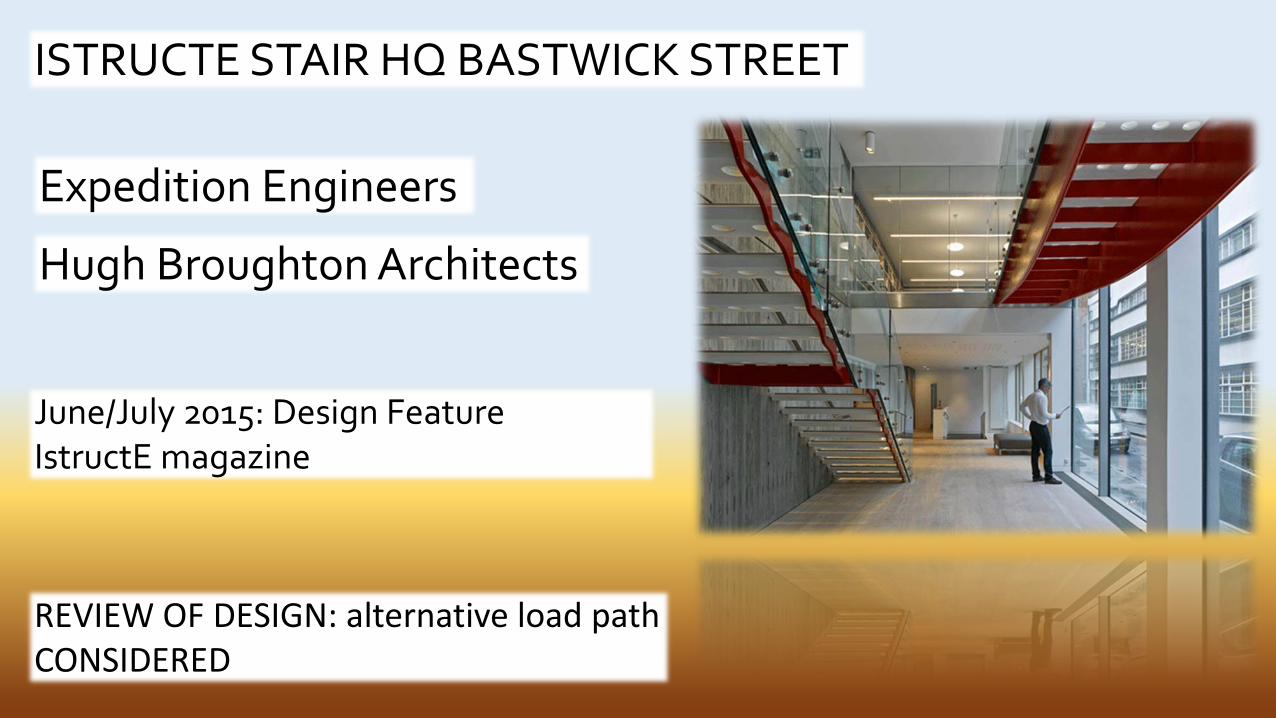
ISTRUCTE STAIR HQ BASTWICK STREET
Expedition Engineers
Hugh Broughton Architects
June/July 2015: Design FeatureIstructE magazine
REVIEW OF DESIGN: alternative load path CONSIDERED


ISTRUCTE STAIR BASTWICK STREET
Traditional Cantilever Stair – Load path
Torsion Increases down the stair
Tread loads accumulate
Torsion and Shear resisted By wall
No cantilever bending

ASSUMPTIONS
1. GLASS balustrade ineffective
4. 50% STAIR and balustrade load cumulatively onto outer stringer
3. 50% STAIR loaded onto wall
5. LOCAL TORSION resisted at each tread by STRINGER DOES NOT ACCUMULATE
2. BARS transfer shears/torsion into wall
6. LANDING supports upper half of FLIGHT

FREE BODY DIAGRAM
Balustrade/stringer/half tread each 1kN
Local applied Torsion (over tread width)= (10-9)x0.25 = 0.25kNm
Resolving Shears at support
R1= T/0.08m+0.8/2=3.6kN (down)
R2=-T/0.08m+0.8/2=-2.7kN(up)
Cumulating loads onto stringer/landing x10 treads max = 10kN
Alternative Load Path
1OkN

INITIAL MODEL - VERIFICATION
Concrete treads 40mm thick (plates)
REACTIONS +3.7/2.8 – OK
STRINGER AXIAL FORCE 10.6kN – OK
‘LIKE WOBBLY TEETH’ – WALL SUPPORTS with VERY LOW PULL OUT STIFFNESS
75x30mm stepped stringer (steel)

INITIAL MODEL DEFLECTIONS
DEFLECTIONS HIGH NO GLASS – 10mm ADDING GLASS – DEFLECTION 0.50mm

REVISED MODEL – FIXED SUPPORTSBy fixing supports shears at support model corresponded to Expedition design
EXPEDITION MODELHORIZONTAL SHEARS
EXPEDITION MODELNO GLASS –DEFLECTION 1mm

EXPEDITION MODEL14.9Hz
REVISED MODEL – NATURAL FREQUENCY
Natural Frequency at 14.9Hz similar to Expedition site observations

DOES THE ALTERNATIVE LOAD PATH MODEL HELP?
SINCE GLASS BALUSTRADE INCLUDED – natural frequency > 14.9Hz
POST DRILLED ANCHORS POSSIBLE (pre-forming holes complicated construction)

CONCLUSION
Sketches and hand calculations used to understand problem
Support loads may be estimated
Elements may be Initially Sized and Checked
Initial COMPUTER MODEL built from FIRST APPROXIMATIONS

EXAMPLES FROM THE BOOKStructural Engineering: Efficacy, Balance and Grace
Simply Supported Beams
Cantilever Beams
Continuous Beams
Framed Structures
Trusses and Vierendeel Structures
Tension and Suspension Structures
Arches, Vaults and Domes
Torsion Structures and Ring Beams
Plate Structures
Deep Beams, Load Carrying Walls and Diaphragms
Dynamics
Learning from Failure

TRIANGULAR LOADING – ASSUMING UDL 2/3 PEAK
Classic Bending Moments/Shears UDL in place of Triangular Loading
Equivalent UDL 2/3 peak
+33% Bending
+0% max shear
+33% deflection

ASSUMING CENTRAL POINT LOAD – WHEN ACTUAL LOAD OFF CENTRE
Classic Bending Moments/Shears Use When Point Load off-centre (up to Middle Third Zone)
Equivalent Assume Central Point Load
+11% Bending
-140% max shear – calculate separately!
+15% deflection

CANTILEVERS
Comparison of Cantilever with Simply Supported
Cantilever with BackspanPoint Load
Increasing backspanTo 4L 4xencastre
Cantilever with BackspanUDL
Increasing backspanUDL backspan increased influence

FRAME STRUCTURES
Wind Frame TraditionalDesign
Wind Loading – Virtual Pins Columns
Design Beams Assuming Simply Supported
Quick estimation of Wind Bending

TRUSSES AND VIERENDEELS – KING POST TRUSSKingpost Truss
Statically Indeterminate
Combination of Beam and Truss Action

TENSION STRUCTURES – FABRIC TENSION ROOF STRUCTURE
Goodwood Racecourse - 1991
NON LINEAR ANALYSIS
Form Finding (dynamic relaxation)
LINEAR ESTIMATION POSSIBLE
Assume line load inFabric (say 3kN/m)
Cable loads from T=PR(utilise railway curves)
External reactions from collected cable loads

TENSION STRUCTURES – FABRIC TENSION ROOF STRUCTURE
Internal Force Diagram
External Forces Net Effect on Supporting Structure

COMPRESSION - CATHEDRAL BUTTRESSING – THE MIDDLE THIRD RULE!
Cathedral Section
Check Foundation thrust-line in middle third
Estimate Buttress (and Pinnacle) weight
Simple thrust from vaulted roof
Geometric check– resolved buttress counterweight

DEEP BEAMSQuick Check Table
Reinforcement Estimate
Lever Arm 0.62d
Check Shear overall rectangular section
Or resolve by STRUT-TIE model

DYNAMICS – DISCOMFORT/PERCEPTION ASSESSMENT
Fundamental Natural Frequencies – tendency for slender structures to resonance
Summary of terms
Fundamental Frequencies
Damping Ratios
Simple Excitation Calculations
Discomfort Criteria
Lateral Frequencies Tall Buildings

FOOTBRIDGE/RAMP 10m SPAN
Actual 10m span structure with screed floor fn 2.6Hz
NATURAL FREQUENCY 2.6Hz. Resonance – LIVELY!
GLASS BALUSTRADE DAMPING

STADIUM CANTILEVER TIER RESPONSE
CALCULATION based DYNAMIC MAGNIFICATION
Response Chart Simplified
STADIUM tier 3.5Hz NATURAL FREQUENCY
Check further < 6 Hz

EXERCISE BOOK
A POCKET COMPANION
FOLLOWS DESIGN PROCESS
15 EXERCISES RELATED TO REALISTIC PROBLEMS
CROSS REFERS TO MAIN BOOK

WHAT NO SPREAD?!
AND FINALLY…STRUCTURAL CURIOSITIES….

STABLE?


THE TALK…..
‘Why’ and ‘How’ the book came to be written
Illustration: Historic and Contemporary structure.
Samples from the book
Conclusion: the benefits of sketching and approximation.

THANK YOU
ANY QUESTIONS?


