1.1. GCT Structural Mortar for use as fire-resistant column coverings.
1.2. For the most recent version of this report, visit drjengineering.org. For more detailed state professional engineering and code compliance legal requirements and references, visit drjengineering.org/statelaw. DrJ is fully compliant with all state professional engineering and code compliance laws.
2.1. 2009, 2012 and 2015 International Building Code (IBC)
2.2. 2009, 2012 and 2015 International Residential Code (IRC)
2.3. ACI 318 – American Concrete Institute Building Code Requirements for Structural Concrete
2.4. ACI 506R – American Concrete Institute Guide to Shotcrete
2.5. ASCE 29 – Standard Calculation Methods for Structural Fire Protection
2.6. ASTM C109 – Standard Test Method for Compressive Strength of Hydraulic Cement Mortars (Using 2-in. or [50-mm] Cube Specimens)
2.7. ASTM C270 – Standard Specification for Mortar for Unit Masonry
2.8. ASTM C387 – Standard Specification for Packaged, Dry, Combined Materials for Mortar and Concrete
2.9. ASTM C780 – Standard Test Method for Preconstruction and Construction Evaluation of Mortars for Plain and Reinforced Unit Masonry.
2.10. ASTM E119 – Standard Test Methods for Fire Tests of Building Construction and Materials
2.11. UL 1709 – Rapid Rise Fire Tests of Protection Materials for Structural Steel
3. Performance Evaluation:
3.1. GCT Structural Mortar listed in Section 1 was evaluated for use as a fire resistant covering for steel columns in accordance with IBC Section 7222 Calculated Fire Resistance and ASCE 29.
3.2. Any code compliance issues not specifically addressed in this section are outside the scope of this TER.
1 Unless otherwise noted, all references in this code compliant research report (TER) are from the 2012 version of the codes and the standards referenced therein, including, but not
limited to, ASCE 7, SDPWS and WFCM. This product also complies with the 2000-2009 and 2015 versions of the IBC and IRC and the standards referenced therein. As required by law, where this research report is not approved, the building official shall respond in writing, stating the reasons this research report was not approved. For variations in state and local codes, if any, see Section 8.
4.1.1.1. GCT Structural Mortar is a single component Type 1 Portland cement containing silica sand and lime, and additives to enhance its bonding strength.
4.1.1.2. The mortar contains micro-spheres with pozzolanic action to make it less permeable and easier to finish.
4.1.1.3. Low-pressure mortar application equipment is highly recommended for speed and quality consistency.
4.1.1.3.1. The mortar has the following characteristics:
4.1.1.3.1.1. Complies with ASTM C387 and ASTM C270, Type M
4.1.1.3.1.2. Compressive strength
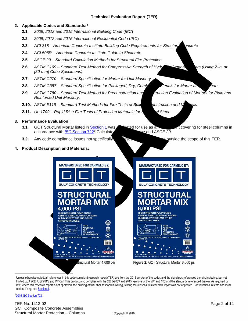
4.1.1.3.1.2.1. 4,000 psi (27.6 MPa) at 28 days for the 4,000 psi mix, Figure 1
4.1.1.3.1.2.2. 6,000 psi (41.4 MPa) at 28 days for the 6,000 psi mix, Figure 2
4.1.1.3.1.3. Maximum aggregate size: 3/16" (4.75 mm)
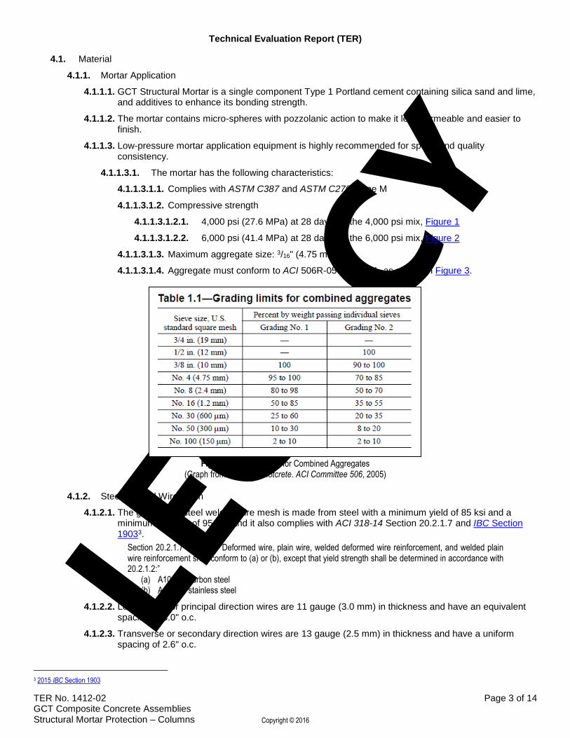
4.1.1.3.1.4. Aggregate must conform to ACI 506R-05 Table 1.1, as shown in Figure 3.
Figure 3: Grading Limit for Combined Aggregates (Graph from Guide to Shotcrete. ACI Committee 506, 2005)
4.1.2. Steel Welded Wire Mesh
4.1.2.1. The galvanized steel welded wire mesh is made from steel with a minimum yield of 85 ksi and a minimum fracture of 95 ksi, and it also complies with ACI 318-14 Section 20.2.1.7 and IBC Section 19033.
Section 20.2.1.7 states — “Deformed wire, plain wire, welded deformed wire reinforcement, and welded plain wire reinforcement shall conform to (a) or (b), except that yield strength shall be determined in accordance with 20.2.1.2:”
5.1.1. The wire mesh is mechanically attached to the steel columns. These connections are designed to support the weight of the applied mortar in accordance with accepted engineering practice.
5.1.2. The mortar is then spray applied using low pressure application equipment and finished in accordance with the construction document specifications.
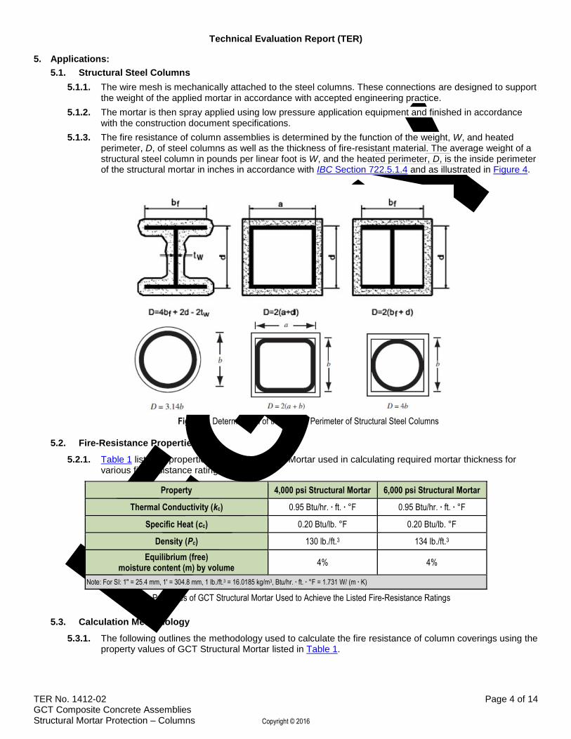
5.1.3. The fire resistance of column assemblies is determined by the function of the weight, W, and heated perimeter, D, of steel columns as well as the thickness of fire-resistant material. The average weight of a structural steel column in pounds per linear foot is W, and the heated perimeter, D, is the inside perimeter of the structural mortar in inches in accordance with IBC Section 722.5.1.4 and as illustrated in Figure 4.
Figure 4: Determination of the Heated Perimeter of Structural Steel Columns
5.2. Fire-Resistance Properties
5.2.1. Table 1 lists the properties of GCT Structural Mortar used in calculating required mortar thickness for various fire-resistance ratings.
Thermal Conductivity (kc) 0.95 Btu/hr. ∙ ft. ∙ °F 0.95 Btu/hr. ∙ ft. ∙ °F
Specific Heat (cc) 0.20 Btu/lb. °F 0.20 Btu/lb. °F
Density (Pc) 130 lb./ft.3 134 lb./ft.3
Equilibrium (free) moisture content (m) by volume
4% 4%
Note: For SI: 1" = 25.4 mm, 1' = 304.8 mm, 1 lb./ft.3 = 16.0185 kg/m3, Btu/hr. ∙ ft. ∙ °F = 1.731 W/ (m ∙ K)
Table 1: Properties of GCT Structural Mortar Used to Achieve the Listed Fire-Resistance Ratings
5.3. Calculation Methodology
5.3.1. The following outlines the methodology used to calculate the fire resistance of column coverings using the property values of GCT Structural Mortar listed in Table 1.
5.3.2. IBC Section 7224 contains provisions for calculating the fire-resistance rating of specific materials or combinations of materials.
5.3.3. The pertinent sections follow:
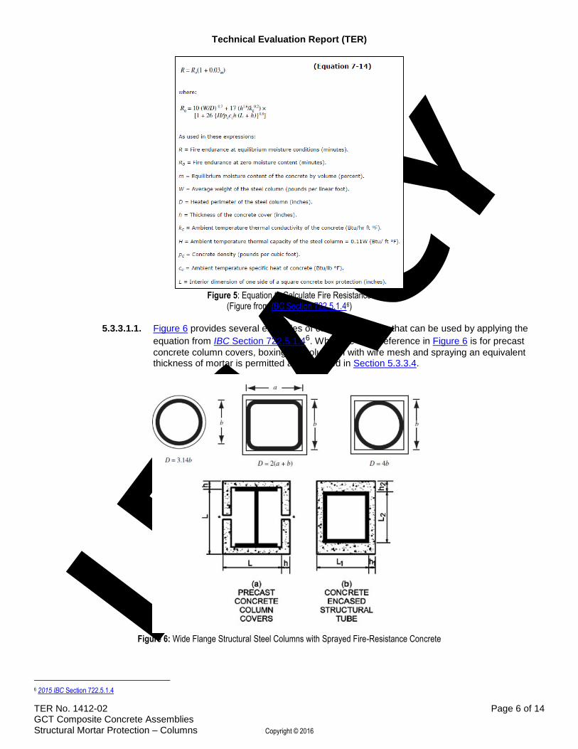
5.3.3.1. IBC Section 722.5.1.45 provides the method for determining the fire-resistance rating of structural steel columns protected with concrete, see Figure 5.
Figure 5: Equation to Calculate Fire Resistance (Figure from IBC Section 722.5.1.46)
5.3.3.1.1. Figure 6 provides several examples of column coverings that can be used by applying the
equation from IBC Section 722.5.1.46. While the code reference in Figure 6 is for precast
concrete column covers, boxing the column in with wire mesh and spraying an equivalent thickness of mortar is permitted as described in Section 5.3.3.4.
5.3.3.1.2. Some configurations of column covers, such as boxed out covers, leave voids between fireproofing on both sides of the column or the web of the beam. If damage to the boxed out covering occurs at both the top and bottom, a flue effect will be created, causing hot gas to pass through the boxing, which will heat the steel column rapidly causing premature failure.
5.3.3.1.2.1. When using a boxed design on columns over 20' high, one firestop must be installed for every 10' of height7.
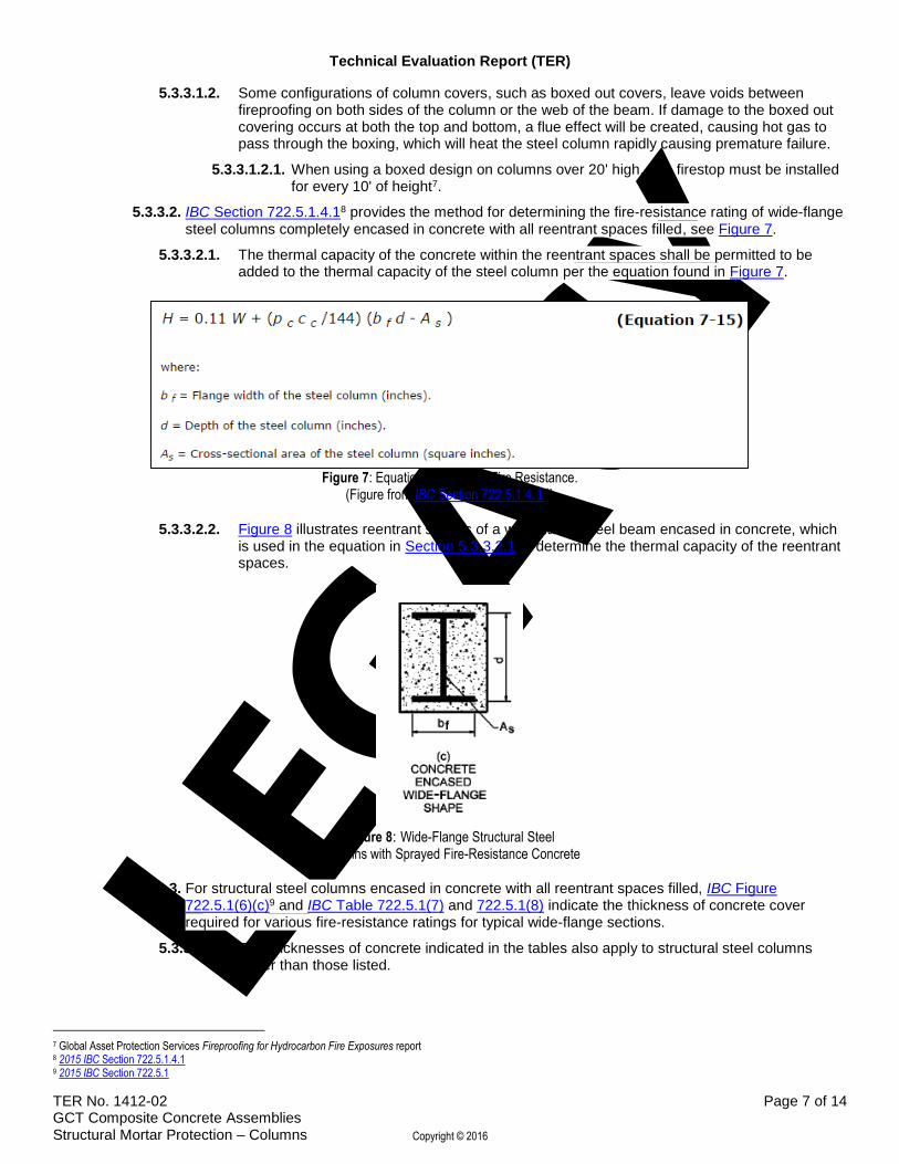
5.3.3.2. IBC Section 722.5.1.4.18 provides the method for determining the fire-resistance rating of wide-flange steel columns completely encased in concrete with all reentrant spaces filled, see Figure 7.
5.3.3.2.1. The thermal capacity of the concrete within the reentrant spaces shall be permitted to be added to the thermal capacity of the steel column per the equation found in Figure 7.
Figure 7: Equation to calculate Fire Resistance. (Figure from IBC Section 722.5.1.4.18)
5.3.3.2.2. Figure 8 illustrates reentrant spaces of a wide-flange steel beam encased in concrete, which is used in the equation in Section 5.3.3.2.1 to determine the thermal capacity of the reentrant spaces.
Figure 8: Wide-Flange Structural Steel Columns with Sprayed Fire-Resistance Concrete
5.3.3.3. For structural steel columns encased in concrete with all reentrant spaces filled, IBC Figure 722.5.1(6)(c)9 and IBC Table 722.5.1(7) and 722.5.1(8) indicate the thickness of concrete cover required for various fire-resistance ratings for typical wide-flange sections.
5.3.3.3.1. The thicknesses of concrete indicated in the tables also apply to structural steel columns larger than those listed.
7 Global Asset Protection Services Fireproofing for Hydrocarbon Fire Exposures report 8 2015 IBC Section 722.5.1.4.1 9 2015 IBC Section 722.5.1
5.3.3.4. For structural steel columns boxed in with the wire mesh, the thickness of the mortar cover shall be determined in accordance with provisions shown for precast concrete covers as shown in IBC Figure 722.5.1(6)(a)10, Table 722.5.1(9) and 722.5.1(10).
5.3.3.4.1. The thicknesses of concrete given in these tables also apply to structural steel columns larger than those listed.
5.4. Fire Test Methods11
5.4.1. ASTM E119
5.4.1.1. The properties of GCT Structural Mortar as listed in Table 1 may be used in calculations to determine thickness of mortar cover required when based on the calculation methods provided above and listed in IBC Section 72212, which are based on ASTM E119 testing protocols.
5.4.2. UL 1709
5.4.2.1. Where the design requires use of UL 1709 to determine the fire resistance of the columns, the calculations above for the ASTM E119 tests shall be adjusted in accordance with Table 2.
Recommended Correlation
ASTM E119 Rating (min.)
30 45 60 90 120 150 180 240 300 360
Corresponding Rating for UL 1709 (min.)
15 30 45 60 90 120 150 240 300 360
Table 2: Comparison of ASTM E119 & UL 1709 Fire Test Assembly Ratings
5.5. Required Minimum Thickness
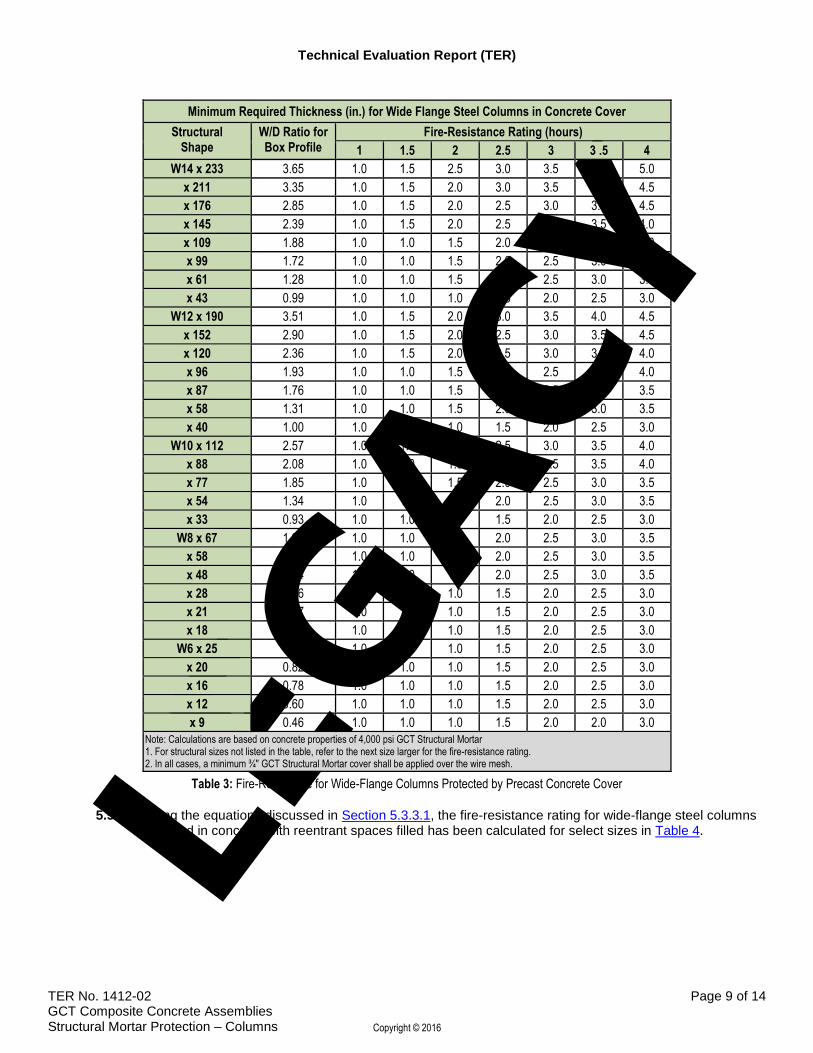
5.5.1. Using the equation discussed in Section 5.3.3.1., the fire-resistance rating for wide-flange steel columns encased with GCT Structural Mortar has been calculated for select sizes in Table 3.
10 2015 IBC Section 722.5.1 11 Section 5.4 test methods table based on testing performed by Global Asset Protection Services under contract with Underwriters Laboratories and published in GAP’s Fireproofing for Hydrocarbon Fire Exposures research report. 12 2015 IBC Section 722
Minimum Required Thickness (in.) for Wide Flange Steel Columns in Concrete Cover
Structural Shape
W/D Ratio for Box Profile
Fire-Resistance Rating (hours)
1 1.5 2 2.5 3 3 .5 4
W14 x 233 3.65 1.0 1.5 2.5 3.0 3.5 4.0 5.0
x 211 3.35 1.0 1.5 2.0 3.0 3.5 4.0 4.5
x 176 2.85 1.0 1.5 2.0 2.5 3.0 3.5 4.5
x 145 2.39 1.0 1.5 2.0 2.5 3.0 3.5 4.0
x 109 1.88 1.0 1.0 1.5 2.0 2.5 3.0 4.0
x 99 1.72 1.0 1.0 1.5 2.0 2.5 3.0 3.5
x 61 1.28 1.0 1.0 1.5 2.0 2.5 3.0 3.5
x 43 0.99 1.0 1.0 1.0 1.5 2.0 2.5 3.0
W12 x 190 3.51 1.0 1.5 2.0 3.0 3.5 4.0 4.5
x 152 2.90 1.0 1.5 2.0 2.5 3.0 3.5 4.5
x 120 2.36 1.0 1.5 2.0 2.5 3.0 3.5 4.0
x 96 1.93 1.0 1.0 1.5 2.0 2.5 3.0 4.0
x 87 1.76 1.0 1.0 1.5 2.0 2.5 3.0 3.5
x 58 1.31 1.0 1.0 1.5 2.0 2.5 3.0 3.5
x 40 1.00 1.0 1.0 1.0 1.5 2.0 2.5 3.0
W10 x 112 2.57 1.0 1.5 2.0 2.5 3.0 3.5 4.0
x 88 2.08 1.0 1.0 1.5 2.0 2.5 3.5 4.0
x 77 1.85 1.0 1.0 1.5 2.0 2.5 3.0 3.5
x 54 1.34 1.0 1.0 1.5 2.0 2.5 3.0 3.5
x 33 0.93 1.0 1.0 1.0 1.5 2.0 2.5 3.0
W8 x 67 1.94 1.0 1.0 1.5 2.0 2.5 3.0 3.5
x 58 1.71 1.0 1.0 1.5 2.0 2.5 3.0 3.5
x 48 1.44 1.0 1.0 1.5 2.0 2.5 3.0 3.5
x 28 0.96 1.0 1.0 1.0 1.5 2.0 2.5 3.0
x 21 0.77 1.0 1.0 1.0 1.5 2.0 2.5 3.0
x 18 0.67 1.0 1.0 1.0 1.5 2.0 2.5 3.0
W6 x 25 1.00 1.0 1.0 1.0 1.5 2.0 2.5 3.0
x 20 0.82 1.0 1.0 1.0 1.5 2.0 2.5 3.0
x 16 0.78 1.0 1.0 1.0 1.5 2.0 2.5 3.0
x 12 0.60 1.0 1.0 1.0 1.5 2.0 2.5 3.0
x 9 0.46 1.0 1.0 1.0 1.5 2.0 2.0 3.0
Note: Calculations are based on concrete properties of 4,000 psi GCT Structural Mortar 1. For structural sizes not listed in the table, refer to the next size larger for the fire-resistance rating. 2. In all cases, a minimum ¾" GCT Structural Mortar cover shall be applied over the wire mesh.
Table 3: Fire-Resistance for Wide-Flange Columns Protected by Precast Concrete Cover
5.5.2. Using the equations discussed in Section 5.3.3.1, the fire-resistance rating for wide-flange steel columns encased in concrete with reentrant spaces filled has been calculated for select sizes in Table 4.
Fire-Resistance Rating (hours) for Wide-Flange Steel Columns with Reentrant Spaces Filled
Structural Shape Minimum Required Thickness (in.)
1 1.5 2 2.5 3 3 .5 4
W14 x 233 2.0 2.5 3.5 4.5 5.0 6.0 7.0
x 211 2.0 2.5 3.5 4.0 5.0 6.0 6.5
x 176 1.5 2.5 3.0 4.0 4.5 5.5 6.5
x 145 1.5 2.5 3.0 4.0 4.5 5.5 6.0
x 109 1.5 2.0 3.0 3.5 4.5 5.0 6.0
x 99 1.5 2.0 3.0 3.5 4.5 5.0 6.0
x 61 1.0 2.0 2.5 3.0 4.0 4.5 5.0
x 43 1.0 1.5 2.0 3.0 3.5 4.0 5.0
W12 x 190 1.5 2.5 3.0 4.0 4.5 5.5 6.0
x 152 1.5 2.5 3.0 3.5 4.5 5.0 6.0
x 120 1.5 2.0 3.0 3.5 4.0 5.0 5.5
x 96 1.5 2.0 2.5 3.5 4.0 5.0 5.5
x 87 1.5 2.0 2.5 3.5 4.0 4.5 5.5
x 58 1.0 2.0 2.5 3.0 3.5 4.5 5.0
x 40 1.0 1.5 2.0 3.0 3.5 4.0 4.5
W10 x 112 1.5 2.0 2.5 3.5 4.0 4.5 5.5
x 88 1.5 2.0 2.5 3.0 4.0 4.5 5.0
x 77 1.5 2.0 2.5 3.0 3.5 4.5 5.0
x 54 1.0 1.5 2.5 3.0 3.5 4.0 5.0
x 33 1.0 1.5 2.0 2.5 3.0 4.0 4.5
W8 x 67 1.0 1.5 2.0 3.0 3.5 4.0 4.5
x 58 1.0 1.5 2.0 3.0 3.5 4.0 4.5
x 48 1.0 1.5 2.0 2.5 3.5 4.0 4.5
x 28 1.0 1.5 2.0 2.5 3.0 3.5 4.0
x 21 1.0 1.0 1.5 2.0 3.0 3.5 4.0
x 18 1.0 1.0 1.5 2.0 2.5 3.5 4.0
W6 x 25 1.0 1.5 1.5 2.0 3.0 3.5 4.0
x 20 1.0 1.0 1.5 2.0 2.5 3.5 4.0
x 16 1.0 1.0 1.5 2.0 2.5 3.0 3.5
x 12 1.0 1.0 1.5 2.0 2.5 3.0 3.5
x 9 1.0 1.0 1.5 2.0 2.5 3.0 3.5
Note: Calculations are based on concrete properties of 4,000 psi GCT Structural Mortar 1. For structural sizes not listed in the table, refer to the next size larger for the fire-resistance rating. 2. In all cases, a minimum ¾" GCT Structural Mortar cover shall be applied over the wire mesh.
Table 4: Fire-Resistance for Concrete Encased Wide-Flange Columns
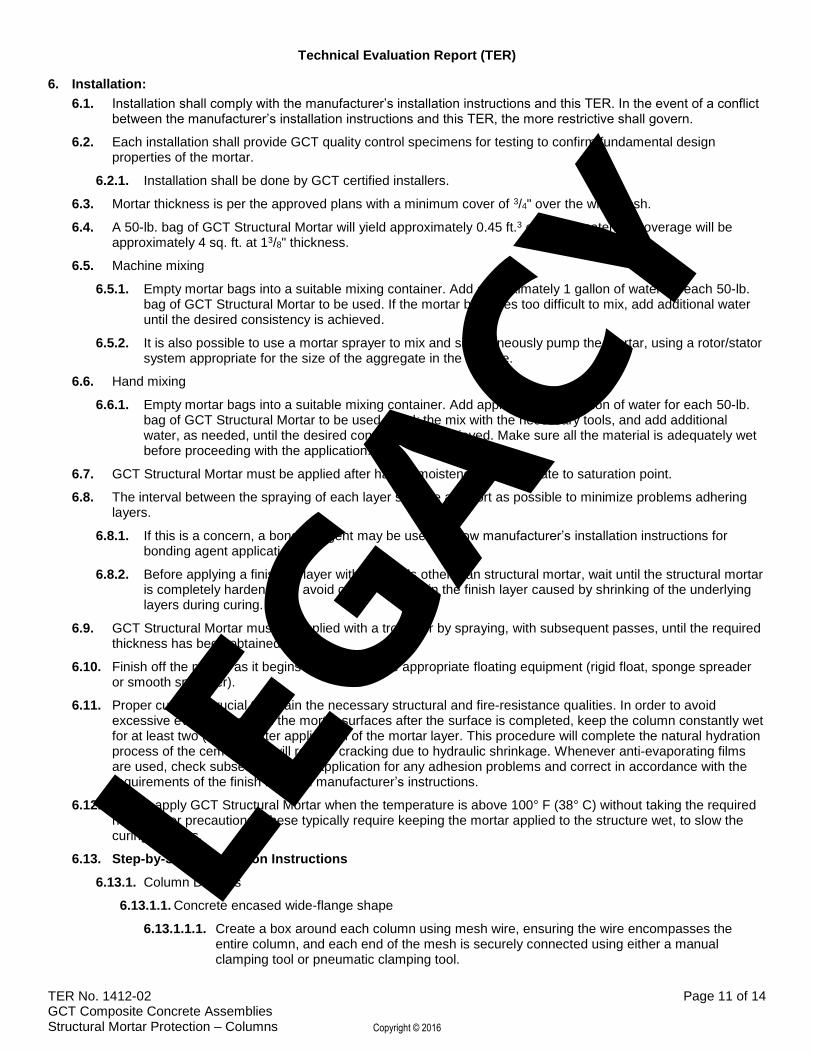
6.1. Installation shall comply with the manufacturer’s installation instructions and this TER. In the event of a conflict between the manufacturer’s installation instructions and this TER, the more restrictive shall govern.
6.2. Each installation shall provide GCT quality control specimens for testing to confirm fundamental design properties of the mortar.
6.2.1. Installation shall be done by GCT certified installers.
6.3. Mortar thickness is per the approved plans with a minimum cover of 3/4" over the wire mesh.
6.4. A 50-lb. bag of GCT Structural Mortar will yield approximately 0.45 ft.3 of mixed material. Coverage will be approximately 4 sq. ft. at 13/8" thickness.
6.5. Machine mixing
6.5.1. Empty mortar bags into a suitable mixing container. Add approximately 1 gallon of water for each 50-lb. bag of GCT Structural Mortar to be used. If the mortar becomes too difficult to mix, add additional water until the desired consistency is achieved.
6.5.2. It is also possible to use a mortar sprayer to mix and simultaneously pump the mortar, using a rotor/stator system appropriate for the size of the aggregate in the mixture.
6.6. Hand mixing
6.6.1. Empty mortar bags into a suitable mixing container. Add approximately 1 gallon of water for each 50-lb. bag of GCT Structural Mortar to be used. Work the mix with the necessary tools, and add additional water, as needed, until the desired consistency is achieved. Make sure all the material is adequately wet before proceeding with the application.
6.7. GCT Structural Mortar must be applied after having moistened the substrate to saturation point.
6.8. The interval between the spraying of each layer shall be as short as possible to minimize problems adhering layers.
6.8.1. If this is a concern, a bonding agent may be used. Follow manufacturer’s installation instructions for bonding agent application.
6.8.2. Before applying a finishing layer with materials other than structural mortar, wait until the structural mortar is completely hardened, to avoid cracks forming in the finish layer caused by shrinking of the underlying layers during curing.
6.9. GCT Structural Mortar must be applied with a trowel or by spraying, with subsequent passes, until the required thickness has been obtained.
6.10. Finish off the mortar as it begins to set, using the appropriate floating equipment (rigid float, sponge spreader or smooth spreader).
6.11. Proper curing is crucial to obtain the necessary structural and fire-resistance qualities. In order to avoid excessive evaporation from the mortar surfaces after the surface is completed, keep the column constantly wet for at least two (2) days after application of the mortar layer. This procedure will complete the natural hydration process of the cement and will reduce cracking due to hydraulic shrinkage. Whenever anti-evaporating films are used, check subsequent finish application for any adhesion problems and correct in accordance with the requirements of the finish material manufacturer’s instructions.
6.12. Do not apply GCT Structural Mortar when the temperature is above 100° F (38° C) without taking the required hot weather precautions. These typically require keeping the mortar applied to the structure wet, to slow the curing process.
6.13. Step-by-Step Installation Instructions
6.13.1. Column Designs
6.13.1.1. Concrete encased wide-flange shape
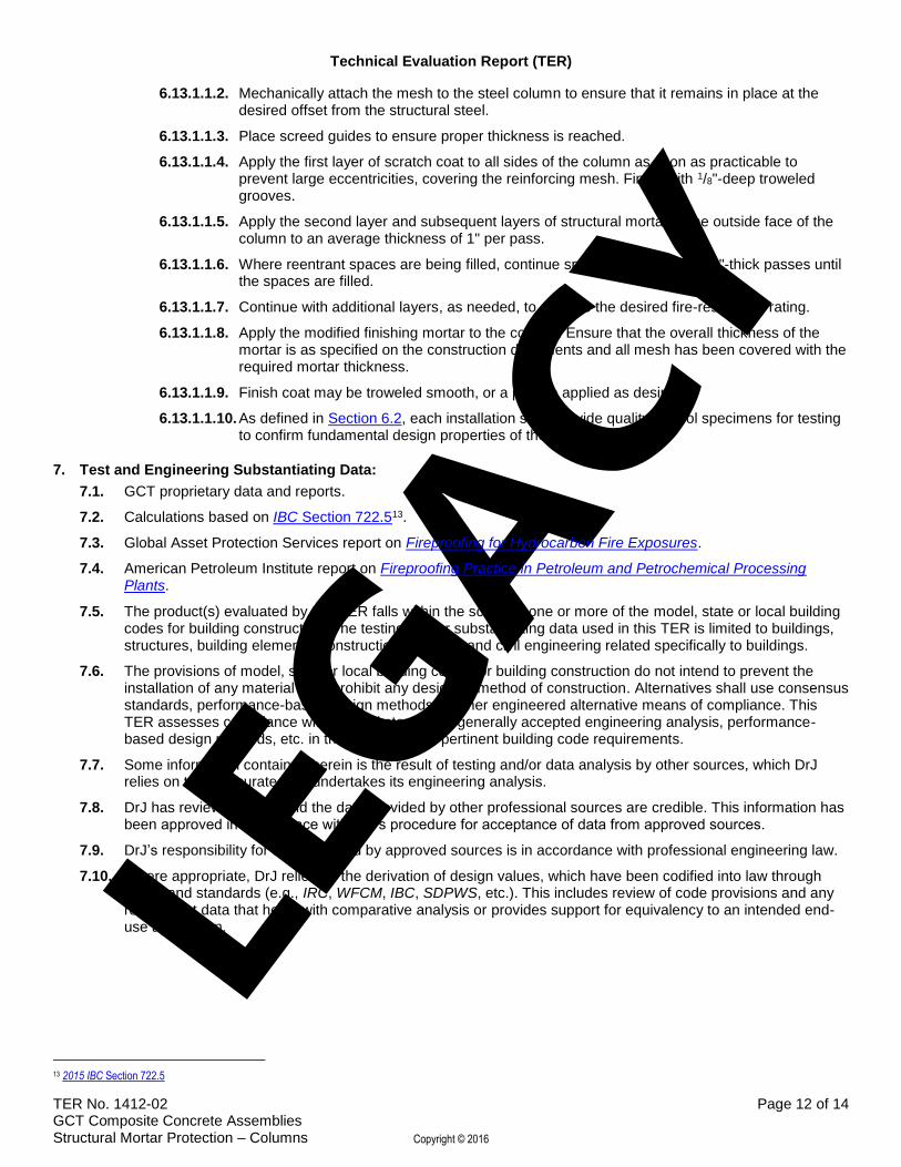
6.13.1.1.1. Create a box around each column using mesh wire, ensuring the wire encompasses the entire column, and each end of the mesh is securely connected using either a manual clamping tool or pneumatic clamping tool.
6.13.1.1.2. Mechanically attach the mesh to the steel column to ensure that it remains in place at the desired offset from the structural steel.
6.13.1.1.3. Place screed guides to ensure proper thickness is reached.
6.13.1.1.4. Apply the first layer of scratch coat to all sides of the column as soon as practicable to prevent large eccentricities, covering the reinforcing mesh. Finish with 1/8"-deep troweled grooves.
6.13.1.1.5. Apply the second layer and subsequent layers of structural mortar to the outside face of the column to an average thickness of 1" per pass.
6.13.1.1.6. Where reentrant spaces are being filled, continue spraying the mortar in 1"-thick passes until the spaces are filled.
6.13.1.1.7. Continue with additional layers, as needed, to achieve the desired fire-resistance rating.
6.13.1.1.8. Apply the modified finishing mortar to the column. Ensure that the overall thickness of the mortar is as specified on the construction documents and all mesh has been covered with the required mortar thickness.
6.13.1.1.9. Finish coat may be troweled smooth, or a pattern applied as desired.
6.13.1.1.10. As defined in Section 6.2, each installation shall provide quality control specimens for testing to confirm fundamental design properties of the mortar.
7. Test and Engineering Substantiating Data:
7.1. GCT proprietary data and reports.
7.2. Calculations based on IBC Section 722.513.
7.3. Global Asset Protection Services report on Fireproofing for Hydrocarbon Fire Exposures.
7.4. American Petroleum Institute report on Fireproofing Practice in Petroleum and Petrochemical Processing Plants.
7.5. The product(s) evaluated by this TER falls within the scope of one or more of the model, state or local building codes for building construction. The testing and/or substantiating data used in this TER is limited to buildings, structures, building elements, construction materials and civil engineering related specifically to buildings.
7.6. The provisions of model, state or local building codes for building construction do not intend to prevent the installation of any material or to prohibit any design or method of construction. Alternatives shall use consensus standards, performance-based design methods or other engineered alternative means of compliance. This TER assesses compliance with defined standards, generally accepted engineering analysis, performance-based design methods, etc. in the context of the pertinent building code requirements.
7.7. Some information contained herein is the result of testing and/or data analysis by other sources, which DrJ relies on to be accurate as it undertakes its engineering analysis.
7.8. DrJ has reviewed and found the data provided by other professional sources are credible. This information has been approved in accordance with DrJ’s procedure for acceptance of data from approved sources.
7.9. DrJ’s responsibility for data provided by approved sources is in accordance with professional engineering law.
7.10. Where appropriate, DrJ relies on the derivation of design values, which have been codified into law through codes and standards (e.g., IRC, WFCM, IBC, SDPWS, etc.). This includes review of code provisions and any related test data that helps with comparative analysis or provides support for equivalency to an intended end-use application.
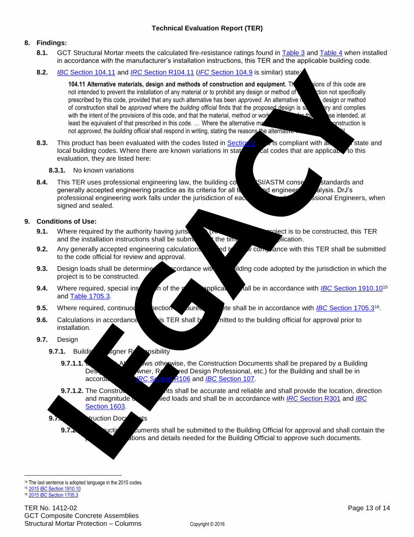
8.1. GCT Structural Mortar meets the calculated fire-resistance ratings found in Table 3 and Table 4 when installed in accordance with the manufacturer’s installation instructions, this TER and the applicable building code.
8.2. IBC Section 104.11 and IRC Section R104.11 (IFC Section 104.9 is similar) state:
104.11 Alternative materials, design and methods of construction and equipment. The provisions of this code are not intended to prevent the installation of any material or to prohibit any design or method of construction not specifically prescribed by this code, provided that any such alternative has been approved. An alternative material, design or method of construction shall be approved where the building official finds that the proposed design is satisfactory and complies with the intent of the provisions of this code, and that the material, method or work offered is, for the purpose intended, at least the equivalent of that prescribed in this code. … Where the alternative material, design or method of construction is not approved, the building official shall respond in writing, stating the reasons the alternative was not approved.14
8.3. This product has been evaluated with the codes listed in Section 2, and is compliant with all known state and local building codes. Where there are known variations in state or local codes that are applicable to this evaluation, they are listed here:
8.3.1. No known variations
8.4. This TER uses professional engineering law, the building code, ANSI/ASTM consensus standards and generally accepted engineering practice as its criteria for all testing and engineering analysis. DrJ’s professional engineering work falls under the jurisdiction of each state Board of Professional Engineers, when signed and sealed.
9. Conditions of Use:
9.1. Where required by the authority having jurisdiction (AHJ) in which the project is to be constructed, this TER and the installation instructions shall be submitted at the time of permit application.
9.2. Any generally accepted engineering calculations needed to show compliance with this TER shall be submitted to the code official for review and approval.
9.3. Design loads shall be determined in accordance with the building code adopted by the jurisdiction in which the project is to be constructed.
9.4. Where required, special inspection of the mortar application shall be in accordance with IBC Section 1910.1015 and Table 1705.3.
9.5. Where required, continuous inspection of poured concrete shall be in accordance with IBC Section 1705.316.
9.6. Calculations in accordance with this TER shall be submitted to the building official for approval prior to installation.
9.7. Design
9.7.1. Building Designer Responsibility
9.7.1.1. Unless the AHJ allows otherwise, the Construction Documents shall be prepared by a Building Designer (e.g., Owner, Registered Design Professional, etc.) for the Building and shall be in accordance with IRC Section R106 and IBC Section 107.
9.7.1.2. The Construction Documents shall be accurate and reliable and shall provide the location, direction and magnitude of all applied loads and shall be in accordance with IRC Section R301 and IBC Section 1603.
9.7.2. Construction Documents
9.7.2.1. Construction Documents shall be submitted to the Building Official for approval and shall contain the plans, specifications and details needed for the Building Official to approve such documents.
14 The last sentence is adopted language in the 2015 codes. 15 2015 IBC Section 1910.10 16 2015 IBC Section 1705.3
9.8.1. The information contained herein is a product, engineering or building code compliance research report performed in accordance with the referenced building codes, testing and/or analysis through the use of accepted engineering procedures, experience and technical judgment.
9.8.2. DrJ research reports provide an assessment of only those attributes specifically addressed in the Products Evaluated or Code Compliance Process Evaluated section.
9.8.3. The engineering evaluation was performed on the dates provided in this TER, within DrJ's professional scope of work.
9.8.4. This product is manufactured under a third-party quality control program in accordance with IRC Section R104.4 and R109.2 and IBC Section 104.4 and 110.4.
9.8.5. The actual design, suitability and use of this research report for any particular building is the responsibility of the Owner or the Owner's authorized agent, and the report shall be reviewed for code compliance by the Building Official.
9.8.6. The use of this TER is dependent on the manufacturer’s in-plant QC, the ISO/IEC 17020 third-party inspection process, proper installation per the manufacturer’s instructions, the Building Official’s inspection and any other code requirements that may apply to assure accurate compliance with the applicable building code.
10. Identification:
10.1. GCT Structural Mortar described in this TER is identified by a label on the board or packaging material bearing the manufacturer’s name, product name, TER number, and other information to confirm code compliance.
10.2. Additional technical information can be found at www.gctm2.com.
11. Review Schedule:
11.1. This TER is subject to periodic review and revision. For the most recent version of this TER, visit drjengineering.org.
11.2. For information on the current status of this TER, contact DrJ Engineering.
Mission and Professional Responsibilities
Product Evaluation Policies
Product Approval – Building Code, Administrative Law and P.E. Law