U. S. DEPARTMENT OF COMMERCE BUILDING MATERIALS AND STRUCTURES REPORT BMS32 Structural Properties of Two Brick-Concrete-Block Wall Con- structions and a Concrete-Block Wall Construction Sponsored by the National Concrete Masonry Association . 1
Transcript
U. S. DEPARTMENT OF COMMERCE
BUILDINGMATERIALS
AND
STRUCTURESREPORT BMS32
Structural Properties of TwoBrick-Concrete-Block Wall Con-
structions and a Concrete-Block Wall
Construction Sponsored by the
National Concrete Masonry
Association
.1
1
The program of research on building materials and structures, carried on by the
National Bureau of Standards, was undertaken with the assistance of the Central Hous-
ing Committee, an informal organization of governmental agencies concerned with
housing construction and finance, which is cooperating in the investigations through a
subcommittee of principal technical assistants.
CENTRAL HOUSING COMMITTEESUBCOMMITTEE ON TECHNICAL RESEARCH
Walter Junge, Chairman. A. C. Shire, Vice Chairman.
Federal Housing Administration. United States Housing Authority.
Sterling R. March, Secretary.
Albert G. Bear,
Veterans' Administration.
Pierre Blouke,Federal Home Loan Bank Board.
Carroll W. Chamberlain,Procurement Division (Treasury).
Joseph M. DallaValle,Public Health Service (Federal Security
Agency).
John Donovan,Farm Security Administration (Agri-
culture).
George E. Knox,Yards and Docks (Navy).
Vincent B. Phelan,
National Bureau of Standards (Com-merce).
Edward A. Poynton,Office of Indian Affairs (Interior).
George W. Trayer,Forest Service (Agriculture).
Elsmere J. Walters,Construction Division (War).
CHAIRMEN OF SECTIONS
Specifications Materials Maintenance
Carroll W. Chamberlain Elsmere J. Walters John H. Schaefer
Mechanical Equipment Methods and Practices
Robert K. Thulman
NATIONAL BUREAU OF STANDARDSSTAFF COMMITTEE ON ADMINISTRATION AND COORDINATION
Hugh L. Dryden, Chairman.
Mechanics and Sound.
Phaon H. Bates, Gustav E. F. Lundell,Clay and Silicate Products. Chemistry.
Hobart C. Dickinson, Addams S. McAllister,Heat and Power. Codes and Specifications.
Warren E. Emley, Henry S. Rawdon,Organic and Fibrous Materials. Metallurgy.
The Forest Products Laboratory of the United States Department of Agriculture
is cooperating with both committees on investigations of wood constructions.
[For list of BMS publications and how to purchase, see cover page III.]
UNITED STATES DEPARTMENT OE COMMERCE • Harry L. Hopkins, Secretary
NATIONAL BUREAU OF STANDARDS • Lyman J. Briggs, Director
BUILDING MATERIALS
and STRUCTURESREPORT BMS32
Structural Properties of Two Brick-Concrete-Block Wall Constructions
and a Concrete-Block Wall
Construction Sponsored by the
National Concrete Masonry Association
by HERBERT L. WHITTEMORE, AMBROSE H. STANG
and Douglas e. parsons
ISSUED NOVEMBER 2, 1939
The National Bureau of Standards is a fact-finding organization;
it does not "approve" any particular material or method of con-
struction. The technical findings in this series ot reports are to
be construed accordingly.
UNITED STATES GOVERNMENT PRINTING OFFICE • WASHINGTON • I939
FOR SALE BY THE SUPERINTENDENT OF DOCUMENTS, WASHINGTON, D. C. • PRICE IO CENTS
Foreword
This report is one of a series issued by the National Bureau of Standards on the
structural properties of constructions intended for low-cost houses and apartments.
These constructions were sponsored by industrial organizations within the building
industry advocating- and promoting their use. The sponsor built and submitted the
specimens described in this report for the program outlined in BMS2, Methods of
Determining the Structural Properties of Low-Cost House Constructions. The sponsor,
therefore, is responsible for the description of the specimens and the method of fabrica-
tion. The Bureau is responsible for the method of testing and the test results.
This report covers only the load-deformation relations and strength of the walls of
a house when subjected to compressive, transverse, racking, impact, and concentrated
loads by standardized methods simulating the loads to which the walls would be subjected
in actual service. Later it may be feasible to determine the heat transmission at ordinary
temperatures and the fire resistance of these same constructions and perhaps other
properties.
The National Bureau of Standards does not "approve" a construction, nor does it
express an opinion as to the merits of a construction for the reasons given in reports
BMSl and BMS2. The technical facts on these and other constructions provide the
basic data from which architects and engineers can determine whether a construction
meets desired performance requirements.
Lyman J. Briggs, Director.
Structural Properties of Two Brick-Concrete-Block Wall Con-structions and a Concrete-Block Wall Construction Sponsored by
the National Concrete Masonry Association
by HERBERT L. WHITTEMORE, AMBROSE H. STA NO, and DOUGLAS E. PARSONS
CONTPage
Foreword nI. Introduction 1
II. Sponsor and product 2
III. Specimens and tests 2
IV. Materials 2
1. Sources of information 2
2. Brick 2
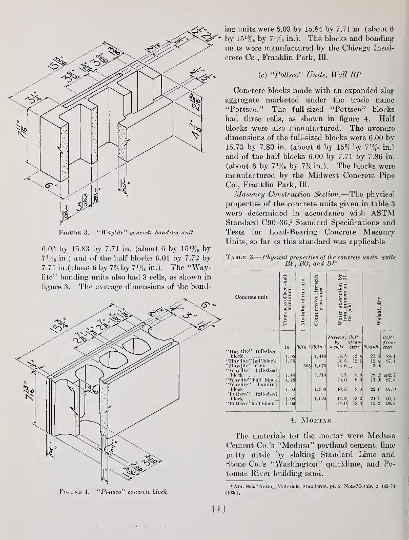
3. Concrete units 3
(a) "Haydite" units, wall BF 3
(b) "Waylite" units, wall BO 3
(c) "Pottsco" units, wall BP 4
4. Mortar 4
V. Fabrication data 5
VI. Wall BF 6
1. Sponsor's statement 6
(a) Description 6
(b) Comments 6
2. Compressive load 6
3. Transverse load 8
4. Concentrated load 8
E N T S
VI. Wall BF—Continued. Page
5. Impact load 10
6. Racking load 10
VII. Wall BO 11
1. Sponsor's statement 11
(a) Description 11
(b) Comments 11
2. Compressive load 12
3. Transverse load 12
4. Concentrated load 14
5. Impact load 14
6. Racking load 15
VIII. Wall BP . 15
1. Sponsor's statement 15
(a) Description 15
(b) Comments 15
2. Compressive load 17
3. Transverse load 17
4. Concentrated load 17
5. Impact load 17
6. Racking load 18
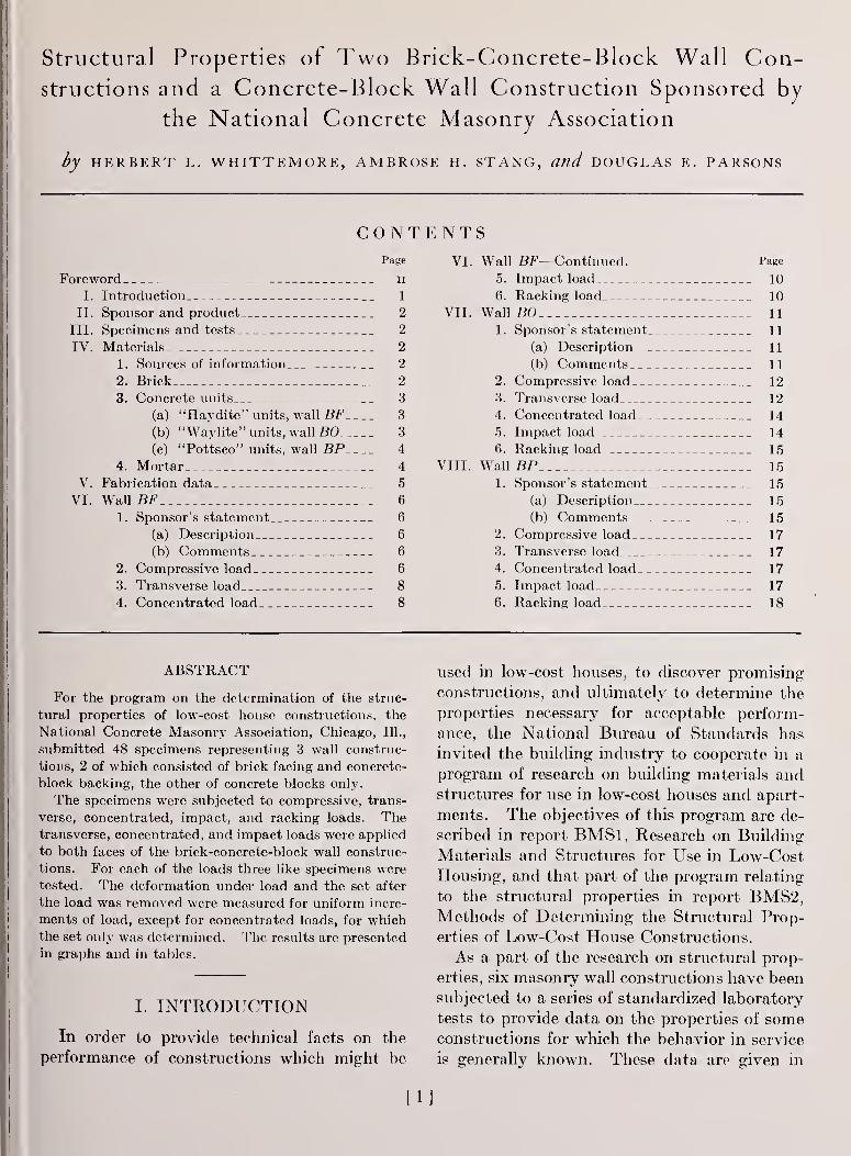
ABSTRACT
For the program on the determination of the struc-
tural properties of low-cost house constructions, the
National Concrete Masonry Association, Chicago, 111.,
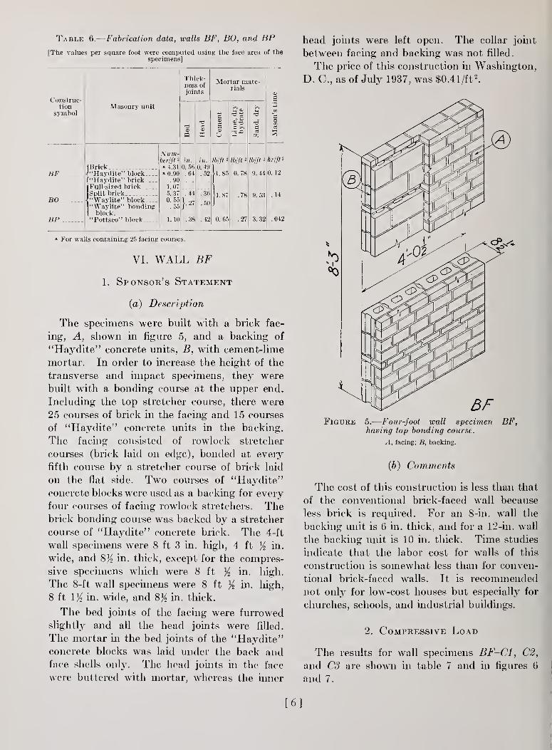
four courses of facing rowlock stretchers. Thebrick bonding course was backed by a stretcher
course of "Haydite" concrete brick. The 4-ft
wall specimens were 8 ft 3 in. high, 4 ft % in.
wide, and 8% in. thick, except for the compres-
sive specimens which were 8 ft K in. high.
The 8-ft wall specimens were 8 ft % in. high,
8 ft IK in. wide, and 8% in. thick.
The bed joints of the facing were furrowed
slightly and all the head joints were filled.
The mortar in the bed joints of the "Haydite"concrete blocks was laid under the back andface shells only. The head joints in the face
were buttered with mortar, whereas the inner
head joints were left open. The collar joint
between facing and backing was not filled.
The price of this construction in Washington,
D. C, as of July 1937, was $0.41 /ft2
.
Figure 5.
—
Four-foot wall specimen BF,having top bonding course.
A, facing; B, backing.
(b) Comments
The cost of this construction is less than that
of the conventional brick-faced wall because
less brick is required. For an 8-in. wall the
backing unit is 6 in. thick, and for a 12-in. wall
the backing unit is 10 in. thick. Time studies
indicate that the labor cost for walls of this
construction is somewhat less than for conven-
tional brick-faced walls. It is recommendednot only for low-cost houses but especially for
churches, schools, and industrial buildings.
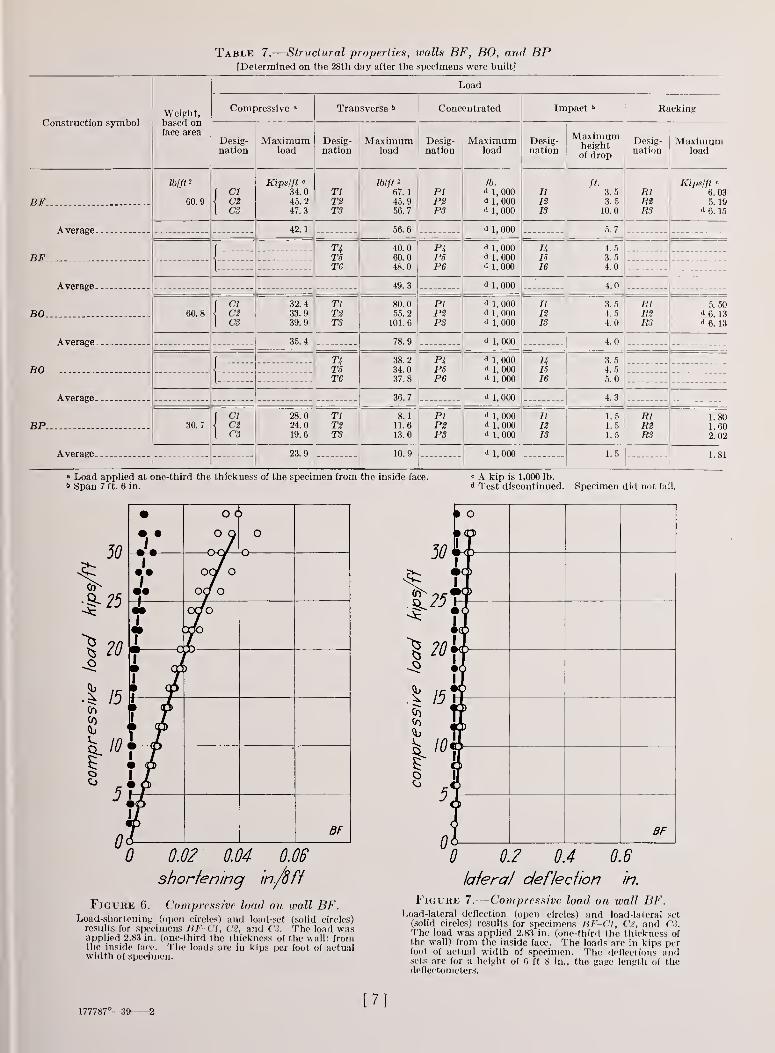
2. Compressive Load
The results for wall specimens BF-C1, C2,
and CS are shown in table 7 and in figures (5
and 7.
[6
Table 7.
—
Structural properties, walls BF, BO, and BP[Determined on the 28th day after the specimens were built]
Load
Construction symbolWeight,based onface area
Compressive a Transverse b Concentrated Impact b Racking
Desig-nation
Maximumload
Desig-nation
Maximumload
Desig-nation
Maximumload
Desig-nation
Maximumheightof drop
Desig-nation
Maximumload
D TPJar.. _
lb/ft 2
ou. y
( CIi C2
Kips/ft «
34.045. 2
TlT2
lb/ft a
67.
1
45.9PIP2
lb.
d 1, 000a
1, 000(l | ooo
11
nft.
3.53.5
RlmKips/ft '
6. 035. 19
1 CS 47 3 TS 56 7 PS 10 10 0 R3 D. 10
Average 42.
1
56. 6 d 1, 000 5.7
f TAT5
40. 0 P4P5
d 1, 000 uIB
4.560.0 d 1, 000 3.5
)I
mo1 0 16 4.0
Average 49. 3 d 1, 000 4.0
OU. of CI\ C2
32. 4
33.9TlT2
80.055.2
piP2
d 1, 000d
1, 00011
IS3.54.5
RlR2
5. 50d 6. 13
1 cs 39. 9 T3 101 6 P3 d ] ooo 13 4.0 R3 d 1 '4u o. lo
Average 35.4 78.9 d 1, 000 4.
0
T4TS
38.2 PhPB
d 1,000d 1,000d
1, 000
uIB
3.534.0 4.5
T6 37.8 P6 16 5.0
Average - 36.7 d 1, 000 4.3
BP. - 30.7f
CI\ C2
28.024.0
TlT2
8.111.6
PIP2
d 1, 000d 1, 000d 1, 000
11
III
1.51.5
RlR2
1.801.60
[ CS 19.6 TS 13.0 PS IS 1.5 RS 2. 02
Average. __ 23.9 10.9 d1, 000 1.5 1.81
« Load applied at one-third the thickness of the specimen from the inside face.
*> Span 7 ft. 6 in.
« A kip is 1,000 lb.d Test discontinued. Specimen did not fail.
10*
BF
0 0.02 0.04 0.06
shortening m./dff
Figure 6.—Compressive load on wall BF.Load-shortening (open circles) and load-set (solid circles)results for specimens BF-C1, C2, and C3. The load wasapplied 2.83 in. (one-third (he thickness of the wall) fromthe inside face. The loads are in kips per foot of actualwidth of specimen.
0 0.2 0.4 0.6
lateral deflection in.
Figure 7.
—
Compressive load on wall BF.Load-lateral deflection (open circles) and load-lateral set
(solid circles) results for specimens BF-C1, C2, and C3.The load was applied 2.83 in. (one-third the thickness ofthe wall) from the. inside face. The loads are in kips perfoot of actual width of specimen. The deflections andsets arc for a height of 6 ft 8 in., the gage length of thedeflectometers.
177787°—39 2[7]
The shortenings and sets for a height of 8 ft
were computed from the values obtained from
the compressometer readings. The compressom-
eters were attached to the specimens, the gage
length being 6 ft 7^ in.
Each of the specimens failed by crushing of
the concrete units in the backing in two or three
60
^ 50]
IA.
20 <
10.
Ot
to
I
1
BF-I
0.2 OA 0.6
defiedion in.
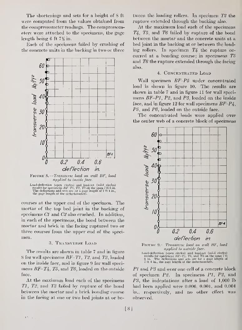
Figure 8.
—
Transverse load on wall BF, loadapplied to inside face.
Load-deflection (open circles) and load-set (solid circles)
results for specimens BF-T1, T%, T3 on the span 7 ft 6 in.
The deflections and sets are for a gage length of 7 ft 4 in.,
the gage length of the deflectometers.
courses at the upper end of the specimen. Themortar of the top bed joint in the backing of
specimens CI and 02 also crushed. In addition,
in each of the specimens, the bond between the
mortar and brick in the facing ruptured two or
three courses from the upper end of the speci-
men.
3. Transverse Load
The results arc shown in table 7 arid in figure
8 for wall specimens BF-T1, T2, and TS, loaded
on the inside face, and in figure 9 for wall speci-
mens BF- rT4, T5, and T6, loaded on the outside
face.
At the maximum load each of the specimens
77, T2, and TS failed by rupture of the bondbetween the mortar and a brick bonding course
hi the facing at one or two bed joints at or be-
tween the loading rollers. In specimen T2 the
rupture extended through the backing also.
At the maximum load each of the specimens
TIf., T5, and T6 failed by rupture of the bondbetween the mortar and the concrete units at a
bed joint in the backing at or between the load-
ing rollers. In specimen T% the rupture oc-
curred at a bonding course; in specimens T5and T6 the rupture extended through the facing
also.
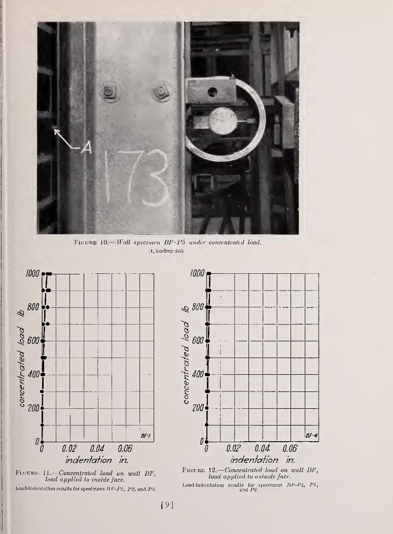
4. Concentrated Load
Wall specimen BF-P5 under concentrated
load is shown in figure 10. The results are
shown in table 7 and in figure 1 1 for wall speci-
mens BF-P1, P2, and PS, loaded on the inside
face, and in figure 12 for wall specimens BF-P4,P5, and P6, loaded on the outside face.
The concentrated loads were applied over
the center web of a concrete block of specimens
60
50
^ 40
30
201
10]
0<
-o
—
ID
(D
ID
<D
BF-4
0 0.60.2 OAo/eflecf/on in
Figure 9.— Transverse load on wall BF, load
applied to outside face.
Load-deflection (open circles) and load-set (solid circles)
results for specimens BF-7%, T5, and T6 on the span 7 ft
6 in. The deflections and sets are for a gage length of
7 ft 4 in., the gage length of the deflectometers.
PI and PS and over one cell of a concrete block
of specimen P2. In specimens PI, P2, and
PS, the indentations after a load of 1,000 lb
had been applied were 0.006, 0.001, and 0.004
in., respectively, and no other effect was
observed.
[8
Figure 10.— Wall specimen BF-P5 under concentrated load.
A, loading disk.
1000
*8
15
»•
>•
•
•
•
1
BF-I
0.02
'indentation in.
Figure 11.
—
Concentrated load on wall BF,load applied to inside face.
Load-indentation results tor specimens BF-P1, P2, and PS.
1000
800
^3
Co
oo
600
400'
200
0
1
1
1»
—
1»
—
1
<»
—
1•
—
1•
1
BF-4
0 0.02 0.04 0.06
indentation in.
Figure 12.
—
Concentrated load on wall BF,load applied to outside face.
Load-indentation results for specimens BF-P4, PS,and P6.
[9]
The concentrated loads were applied to a
brick in a bonding course of specimens PJ+ and
P5 and to a brick in a rowlock course of speci-
men P6. In specimens P4, P5, and P6, the
indentations after a load of 1,000 lb had been
applied were 0.002, 0.001, and 0.001 in.,
respectively, and no other effect was observed.
10
8
^ 6
1—
•
c '
•
—
»
—
O
-o—
• c 1'
• —o
—
•
—
D
1
—
ri
—
o
o o
-o
—
ocy" O
—
o
i*
BF-I
0 0.4 0.8 1.2
deflection in.
Figure 13.
—
Impact load on wall BF, loadapplied to inside face.
Height of drop-deflection (open circles) and height ofdrop-set (solid circles) results for specimens BF-I1, 12,
and IS on the span 7 ft 6 in.
5. Impact Load
The results are shown in table 7 and in figure
13 for wall specimens BF-I1, 12, and IS,
loaded on the inside face, and in figure 14 for
wall specimens BF-I4, 15, and 16, loaded on
the outside face.
In each of the specimens II, 12, and IS at
drops of 2.5, 2, and 2 ft, respectively, the bondbetween the mortar and the brick ruptured at a
bed joint in the facing near midspan. At drops
of 3, 3, and 4.5 ft, respectively, the bondbetween the mortar and the concrete units rup-
tured at a bed joint in the backing at about the
same height as the cracks in the facing. At the
maximum drop each of these specimens failed
by opening of these cracks or by rupture of
other bed joints. The failure of specimen IS
occurred at a bonding course.
In each of the specimens 14, 15, and 16 at a
drop of 2 ft the bond between the mortar andthe concrete units ruptured at a bed joint in
the backing near midspan. At drops of 3, 3,
and 2.5 ft, respectively, the bond between the
mortar and the brick ruptured at a bed joint
in the facing at the same height. At the max-imum drop each specimen failed by opening of
these cracks. The failure of specimen 16
occurred at a bonding course.
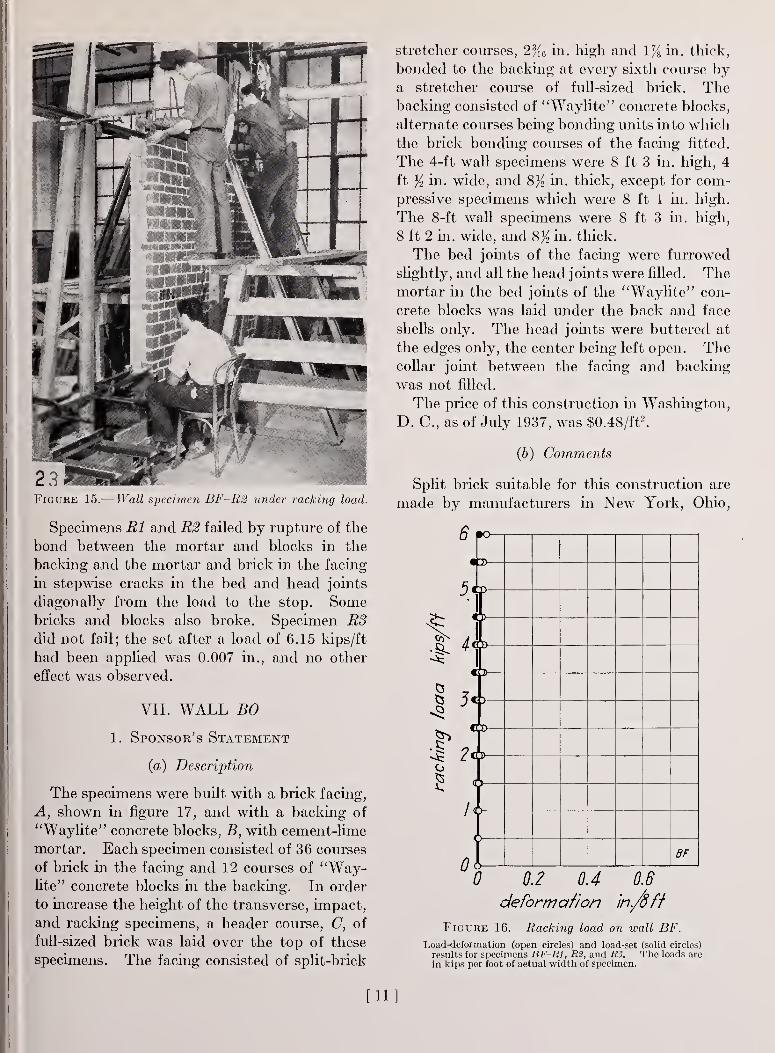
6. Racking Load
Wall specimen BF-R2 under racking load is
shown in figure 15. The results for wall speci-
3
% 2
%-5:
0
-•—
1
—
o
—o—
-O—
|
j
•••
1
—
o
~°7 —O-
•••
/
-—
t
3
uI
iL BF-4
0 0.4 0.8 12deflection 'in.
Figure 14.
—
Impact load on wall BF, load
applied to outside face.
Height of drop-deflection (open circles) and height of
drop-set (solid circles) results for specimens BF-U, IS,
and 16 on the span 7 ft 6 in.
mens BF-R1, R2, and R8 are shown in table
7 and in figure 16.
The deformations and sets shown in figure 16
were computed from the measuring-device
readings. The gage length of the vertical
measuring device was 6 ft 7% in. The gage
length of the horizontal measuring device was
5 ft 0 in.
[10]
78 in. thick,u
2 3 Wkm :
.
Figure 15.— Wall specimen BF-R2 under racking load.
Specimens Rl and R2 failed by rupture of the
bond between the mortar and blocks in the
backing and the mortar and brick in the facing
in stepwise cracks in the bed and head joints
diagonally from the load to the stop. Somebricks and blocks also broke. Specimen R3did not fail; the set after a load of 6.15 kips/ft
had been applied was 0.007 in., and no other
effect was observed.
VII. WALL BO
1. Sponsor's Statement
(a) Description
The specimens were built with a brick facing,
A, shown in figure 17, and with a backing of
"Waylite" concrete blocks, B, with cement-lime
mortar. Each specimen consisted of 36 courses
of brick in the facing and 12 courses of "Way-lite" concrete blocks in the backing. In order
to increase the height of the transverse, impact,
and racking specimens, a header course, C, of
full-sized brick was laid over the top of these
specimens. The facing consisted of split-brick
stretcher courses, 2% 6 in. high and 1
bonded to the backing at every sixth course bya stretcher course of full-sized brick. Thebacking consisted of "Waylite" concrete blocks,
alternate courses being bonding units into which
the brick bonding courses of the facing fitted.
The 4-ft wall specimens were 8 ft 3 in. high, 4
ft }'i in. wide, and %}{ in. thick, except for com-pressive specimens which were 8 ft 1 in. high.
The 8-ft wall specimens were 8 ft 3 in. high,
8 ft 2 in. wide, and 8% in. thick.
The bed joints of the facing were furrowed
slightly, and all the head joints were filled. Themortar in the bed joints of the "Waylite" con-
crete blocks was laid under the back and face
shells only. The head joints were buttered at
the edges only, the center being left open. Thecollar joint between the facing and backing
was not filled.
The price of this construction in Washington,
D. C, as of July 1937, was $0.48/ft2.
(b) Comments
Split brick suitable for this construction are
made by manufacturers in New York, Ohio,
6 p°
5<>
)
—
D
)
BF
0 0.2 0.4 0.6
deformation in./off
Figure 16.
—
Racking load on wall BF.
Load-deformation (open circles) and load-set (solid circles)
results for specimens BF-R1, R2, and R3. The loads are
in kips per foot of actual width of specimen.
[11]
Minnesota, and Illinois. At present split
brick are available only in face brick. If tbe
price is about one-half the price of standard-
sized brick, a substantial decrease in the cost
of the wall can be realized.
Figure 17.
—
Four-foot wall specimen BO,having top header course.
A, facing; B, backing; C, header course.
2. Compressive Load
The results for wall specimens B0-C1, C2,
and CS are shown in table 7, and in figures 18
and 19. The shortenings and sets shown in
figure 18 for a height of 8 ft were computedfrom the values obtained from the compres-
someter readings. The compressometers for
specimen CI were attached to the specimen,
the gage length being 7 ft f in. The compres-
someters for specimens C2 and CS were attached
to the upper and lower bearing plates, the gage
length being 8 ft 1 in. The computed shorten-
ings in 8 ft for specimen CI were less than the
shortenings in 8 ft for specimens C2 and CS.
Each of the specimens failed by crushing of
the concrete blocks in the backing in two or
three courses at the upper end of the specimen.
In specimen CS the bond between the mortar
and brick ruptured in a course near the upper
end of the specimen.
3. Transverse Load
The results are shown in table 7 and in figure
20 for wall specimens BO - T1,T2, and T8, loaded
on the inside face, and in figure 21 for wall
specimens BO-T4, T5, and T6, loaded on the
outside face.
Each of the specimens Tl, T2, T8, T4, and
T6 failed by rupture of the bond between the
mortar and brick at a bed joint in the facing
and between the mortar and concrete blocks at
a bed joint in the backing at or between the
loading rollers. The break appeared first in the
face opposite the load and then extended to the
loaded face. In specimen T5 at a load of 28
30
^ 20
.§!x
b 10
roo
0
0 j o o
• • o / 0 o
Jo loo
1
/ °0
f" ° / oo
m o I CO
WO /CD
V BO
0 0.0/ 0.04 0.06
shorfeninq in/8 ft
Figure 18.
—
Compressive load on wall BO.
Load-shortening (open circles) and load-set (solid circles)
results for specimens BO-C1, C2, and CS. The load wasapplied 2.83 in. (one-third the thickness of the wall) fromthe inside face. The loads are in kips per foot of actualwidth of specimens.
lb/ft2 the bond between the mortar and con-
crete blocks ruptured at a bed joint near mid-
span, and at a load of 30 lb/ft2 the bond between
the mortar and the brick ruptured at a bed
joint at the same height. At the maximum
12]
40
0 0.04 0.08
lateral defiedion in.
Figure 19.
—
Compressive load on wall BO.Load-lateral deflection (open circles) and load-lateral set (solid
circles) results for specimens B0-C1, Ct, and CS. The loadwas applied 2.83 in. (one-third the thickness of the wall)from the inside face. The loads are in kips per foot of actualwidth of specimen. The deflections and sets are for a heightof 7 ft 8 in., the gage length of the deflectometers.
100
80
1
40
20
0
• o
•
—
c
0
• • o o
• • o o
) o
MO
u
po
so-/
0 0.02 0.04 0.06
deflection in.
Figure 20.—Transverse load on wall BO, loadapplied to inside face.
Load-deflection (open circles) and load-set (solid circles)results for specimens BO-Tl, T2, and T3 on the span 7 ftb in. The deflections and sets are for a gage length of 7 fto in., the gage length of the deflectometers.
^ 20
5:
I10
0
CD
O •1O • o
o
D Jf o
r—r
—BO-4
0 0.1 0.2 0.3 0.4
load
deflection in.
Figure 21.
—
Transverse load on wall BO,applied to outside face.
Load-deflection (open circles) and load-set (solid circles) resultsfor specimens BO-Ti, TS, and T6 on the span 7 ft 6 in. Thedeflections and sets are for a gage length of 7 ft 6 in., the gagelength of the deflectometers.
1000
800
!
600
400
200 4
I»
—
•
—
1
1
1
rTr
i
1•
1•BO-I
0 0.02 0.04 0.06
indenialion in.
jue 22.-—Concentrated load on wall BO,load, applied to inside face.
Load-indentation results for specimens BO-PI, P2, and PS.
FlGUl
[13]
5§800
600
400
200
0
•
l
o••1
I
II1
1
1
l
»•
»•
»•1
1
1
<
1
»
1m00-4
0 0,0? 0,04 0,06
indenfalion in.
Figure 23.
—
Concentrated load on wall BO, loadapplied to outside face.
Load-indentation results for specimens BO-P4, P5, and P6.
B0-I1, 12, and 13, loaded on the inside face,
and in figure 26 for wall specimens B0-I4, 15,
and 16, loaded on the outside face.
In specimens II, 12, and 13 at drops of 2.5,
4, and 2 ft, respectively, the bond between the
mortar and brick ruptured at a bed joint in the
facing near midspan. At drops of 3, 4.5, and
3 ft, respectively, the bond between the mortar
and concrete blocks ruptured at a bed joint in
the backing near midspan. At the maximumdrops the specimens failed by opening of these
cracks.
In specimens Uf, 15, and 16 at drops of 1.5, 2,
and 1.5 ft, respectively, the bond between the
mortar and concrete blocks ruptured at a bed
joint in the backing near midspan. At drops
of 2.5, 3, and 3 ft, respectively, the bondbetween the mortar and brick ruptured at a
bed joint in the facing near midspan. At the
maximum drops the specimens failed by open-
ing of these cracks.
The failure in each specimen under impact
load occurred at a bonding course.
load this specimen failed by opening of these
cracks. The cracks in specimens T2, T5, andT6 occurred at bonding courses in the facing
and backing.
4. Concentrated Load
The results are shown in table 7 and in figure
22 for wall specimens BO-PI, P2, and P3,
loaded on the inside face and in figure 23 for
wall specimens B0-P4, P5, and P6, loaded onthe outside face.
The concentrated loads were applied over
one cell of a concrete block of specimens PI,
P2, and P3, and on a split brick of specimens
P4, P5, and P6. In specimens PI, P2, PS, P4,
P5, and P6, the indentations after a load of
1,000 lb had been applied were 0.011, 0.004,
0.005, 0.006, 0.000, and 0.003 in., respectively,
and no other effect was observed.
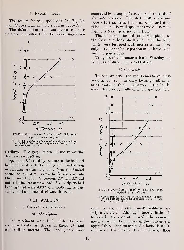
5. Impact Load
Wall specimen BO-IS during the impact test
is shown in figure 24. The results are shown in
table 7 and in figure 25 for wall specimensKitiuius 24.— Wall specimen BO-1J dariiuj the impact
test.
[14
6. Racking Load
The results for wall specimens B0-R1, R2,
and RS are shown in table 7 and in figure 27.
The deformations and sets shown in figure
27 were computed from the measuring-device
3
5 2
0
1—•1
• •
—o-• •
—
c
—o — -o
1
s
uo
I30-1
0 0.2 OA 0.6
defiedion in.
Figure 25.
—
Impact load on wall BO, loadapplied to inside face.
Height of drop-deflection (open circles) and height of drop-set (solid circles) results for specimens BO-II, 12, andIS on the span 7 ft 6 in.
readings. The gage length of the measuring
device was 6 ft 9% in.
Specimen Rl failed by rupture of the bed and
head joints of both the facing and the backing
in stepwise cracks diagonally from the loaded
corner to the stop. Some brick and concrete
blocks also broke. Specimens R2 and R3 did
not fail; the sets after a load of 6.13 kips/ft hadbeen applied were 0.002 and 0.005 in., respec-
tively, and no other effect was observed.
VIII. WALL BP
1. Sponsor's Statement
(a) Description
The specimens were built with "Pottsco"
concrete blocks, as shown in figure 28, andcement-lime mortar. The head joints were
staggered by using half stretchers at the ends of
alternate courses. The 4-ft wall specimens
were 8 ft 2 in. high, 4 ft 0 in. wide, and 6 in.
thick. The 8-ft wall specimens were 8 ft 2 in.
high, 8 ft y2 in. wide, and 6 in. thick.
The mortar in the bed joints was placed at
the front and back shells only, and the headjoints were buttered with mortar at the faces
only, leaving the inner portion of both the head
and bed joints open.
The price of this construction in Washington,
D. C, as of July 1937, was $0.31/ft2.
(b) Comments
To comply with the requirements of mostbuilding codes, a masonry bearing wall mustbe at least 8 in. thick. However, in the South-
west, the bearing walls of many garages, one-
0 0.2 0.4
defiedion
0.6
in.
Figure 26.
—
Impact load on wall BO, loadapplied to outside face.
Height of drop-deflection (open circles) and height of drop-set (solid circles) results for specimens BO-Ii, 15, and16, on the span 7 ft 6 in.
story houses, and other small buildings are
only 6 in. thick. Although there is little dif-
ference in the cost of 6- and 8-in. concrete
masonry walls, the increase in the floor area is
appreciable. For example, if a house is 24 ft.
square on the outside, the increase in floor
[15]
area is 15 it2
, an appreciable increase in the
size of the room.
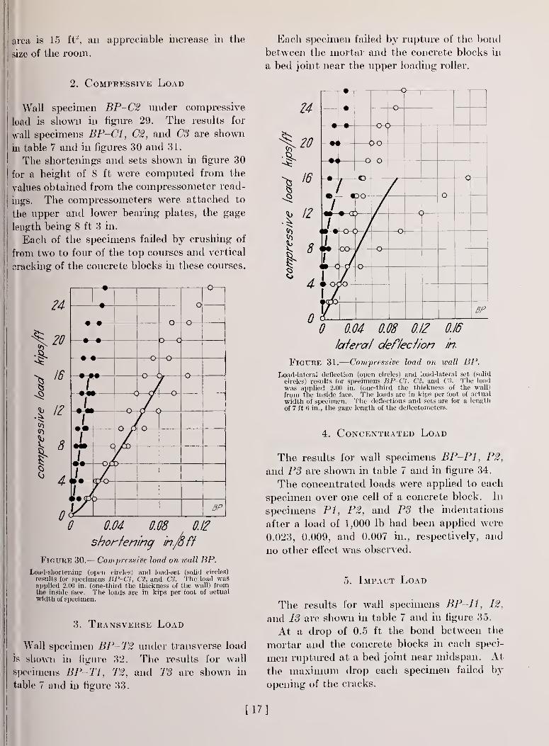
2. Compressive Load
Wall specimen BP-C2 under compressive
load is shown in figure 29. The results for
wall specimens BP-C1, C2, and CS are shown
in table 7 and in figures 30 and 31.
The shortenings and sets shown in figure 30
for a height of 8 ft were computed from the
values obtained from the compressometer read-
ings. The compressometers were attached to
the upper and lower bearing plates, the gage
length being 8 ft 3 in.
Each of the specimens failed by crushing of
from two to four of the top courses and vertical
cracking of the concrete blocks in these courses.
Each specimen failed by rupture of the bond
between the mortar and the concrete blocks in
a bed joint near the upper loading roller.
1
•I
r(J
24
20
16
12
8
4
0
—
o
—•
—o--o
—
• •
—
•
• 0—
c
—
o
—o
—
-o
—o-
I-m^m
f•m/
*°
/
c
1
y BP
0 0.04 0.08 0.12
shortening in.fa ft
Figure 30.
—
Compressive load on wall BP.
Load-shortening (open circles) and load-set (solid circles)
results for specimens HP-C1, Ct, and CSS. The load wasapplied 2.00 in. (one-third the thickness of the wall) fromthe inside face. The loads are in kips per foot of actualwidth of specimen.
3. Transverse Load
Wall specimen BP-T2 under transverse load
is shown in figure 32. The results for wall
specimens BP-T1, T2, and T3 are shown in
table 7 and in figure 33.
r
24
20
16
12
8
4
0
w rV-
-o-i\- •- )
•*
k•«r—\j
-o
—\J—
0•I
0
/
J.17m c
1
ex
-O-C
)
—
y-f-—
o
OO -o-
o1
BP
0.04 0.08 0.12 0.16
lateral deflection in.
Figure 31.
—
Compressive load on wall BP.
Load-lateral deflection (open circles) and load-lateral set (solid
circles) results for specimens BP-C1. C2, and CS. The load
was applied 2.00 in. (one-third the thickness of the wall)
from the inside face. The loads are in kips per foot of actual
width of specimen. The deflections and sets are for a length
of 7 ft fi in., the gage length of the deflectometers.
4. Concentrated Load
The results for wall specimens BP-PI, P2,
and PS are shown in table 7 and in figure 34.
The concentrated loads were applied to each
specimen over one cell of a concrete block. In
specimens PI, P2, and PS the indentations
after a load of 1,000 lb had been applied were
0.023, 0.009, and 0.007 in., respectively, and
no other effect was observed.
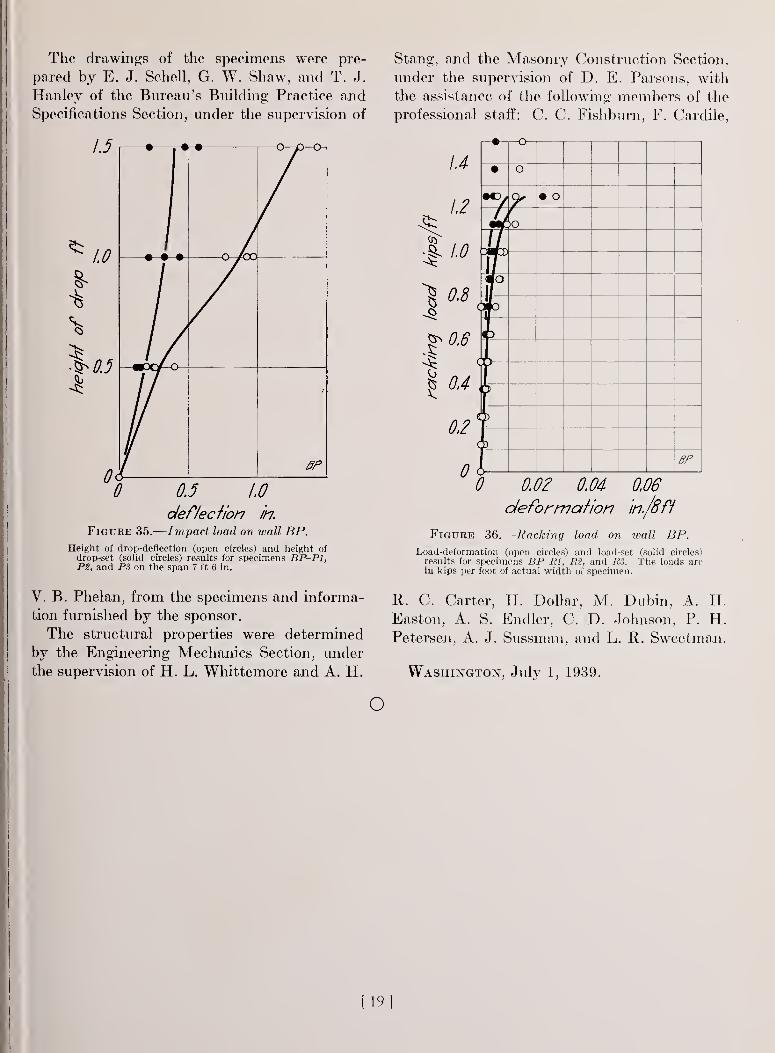
5. Impact Load
The results for wall specimens BP-I1, 12,
and IS are shown in table 7 and in figure 35.
At a drop of 0.5 ft the bond between the
mortar and the concrete blocks in each speci-
men ruptured at a bed joint near midspan. At
the maximum drop each specimen failed by
opening of the cracks.
[17]
6. Racking Load
The results for BP-R1, R2, and R3 are
shown in table 7 and in figure 36.
The deformations and sets shown in figure 36
for a height of 8 ft were computed from the
measuring-device readings. The gage length
of the measuring device was 6 ft 10% in.
12
Figure 32.— Wall specimen BP—T2 under transverseload.
At loads of 1.47, 1.25, and 1.62 kips/ft onspecimens Rl, R2, and R3, respectively, each
specimen cracked through the bed and head
joints diagonally from the loaded corner to the
stop. At the maximum load each specimen
failed by rupture of these joints and, in speci-
men R3, by rupture of the bed and head joints
along another line diagonally from the loaded
corner to the stop. In addition, two concrete
blocks broke in specimens R2 and R3.
JO
8
<S c^ 0
* 4
I
^ 2
0
) •
m 1 J—
1 —
•
<
—o—
•
—
-o
—
)
o> /—
•
—
•
T/ o-—o
—
/
T7
f
BP
0 0.1 0.2
deflection in.
Figure 33.— Transverse load on wall BP.
Load-deflection (open circles) and load-set (solid circles)
results for specimens BP-T1, TZ, and T3 on the span7 ft 6 in. The deflections and sets are for a length of7 ft 6 in., the gage length of the deflectometers.
1000
=§ 800
600
400
200
1
•
—
-••
1
1
1
1• -
1
1
1•
—
•BP
0 0.02 0.04 0.06
indentation in.
Figure 34.
—
Concentrated load on wall BP.
Load-indentation results for specimens BP-PI, P2, and PS.
[18]
The drawings of the specimens were pre-
pared by E. J. Schell, G. W. Shaw, and T. J.
Hanley of the Bureau's Building Practice and
Specifications Section, under the supervision of
Figure 35.-
0.5 1.0
deflection in.
Impact load on wall BP.
Height of drop-deflection (open circles) and height ofdrop-set (solid circles) results for specimens BP-PI,P2, and PS on the span 7 ft 6 in.
V. B. Phelan, from the specimens and informa-
tion furnished by the sponsor.
The structural properties were determined
by the Engineering Mechanics Section, under
the supervision of H. L. Whittemore and A. H.
Stang, and the Masonry Construction Section,
under the supervision of D. E. Parsons, with
the assistance of the following members of the
professional staff: C. C. Fishburn, F. Cardile,
1.4
1.2
1 0.8
^0,6
g 04
0,2
0
• o
• o
>o
uIfITo
a 0
»
BP
0 0.02 0.04 0.06
deformation in./8ft
Figure 36.
—
Racking load on wall BP.
Load-deformation (open circles) and load-set (solid circles)
results for specimens BP-PI, P2, and PS. The loads arein kips per foot of actual width of specimen.
R. C. Carter, H. Dollar, M. Dubin, A. H.
Easton, A. S. Endler, C. D. Johnson, P. H.Petersen, A. J. Sussman, and L. R. Sweetman.
Washington, July 1, 1939.
o
[19]
BUILDING MATERIALS AND STRUCTURES REPORTSThe following publications in this series are now available by purchase from the
Superintendent of Documents at the prices indicated:
BMS1 Research on Building Materials and Structures for Use in Low-Cost Housing 100BMS2 Methods of Determining the Structural Properties of Low-Cost House Constructions 100BMS3 Suitability of Fiber Insulating Lath as a Plaster Base 100BMS4 Accelerated Aging of Fiber Building Boards 100BMS5 Structural Properties of Six Masonry Wall Constructions 150BMS6 Survey of Roofing Materials in the Southeastern States 150BMS7 Water Permeability of Masonry Walls \&b
a/PBMS8 Methods of Investigation of Surface Treatment for Corrosion Protection of Steel 100BMS9 Structural Properties of the Insulated Steel Construction Co's. "Frameless-Steel"
Constructions for Walls, Partitions, Floors, and Roofs 100BMS10 Structural Properties of One of the "Keystone Beam Steel Floor" Constructions Spon-
sored by the H. H. Robertson Co 100BMS11 Structural Properties of the Curren Fabrihome Corporation's "Fabrihome" Construc-
tions for Walls and Partitions 100BMS12 Structural Properties of "Steelox" Constructions for Walls, Partitions, Floors, and Roofs
Sponsored by Steel Buildings, Inc 150BMS13 Properties of Some Fiber Building Boards of Current Manufacture 100BMS14 Indentation and Recovery of Low-Cost Floor Coverings 100BMS15 Structural Properties of "Wheeling Long-Span Steel Floor" Construction Sponsored by
the Wheeling Corrugating Co 100BMS16 Structural Properties of a "Tilecrete" Floor Construction Sponsored by Tilecrete Floors,
Inc 100BMS17 Sound Insulation of Wall and Floor Constructions 100 SLo<f-
BMS18 Structural Properties of "Pre-Fab" Constructions for Walls, Partitions, and FloorsSponsored by the Harnischfeger Corporation 100
BMS19 Preparation and Revision of Building Codes 150BMS20 Structural Properties of "Twachtman" Constructions for Walls and Floors Sponsored by
Connecticut Pre-Cast Buildings Corporation 100BMS21 Structural Properties of a Concrete-Block Cavity-Wall Construction Sponsored by the
National Concrete Masonry Association 100BMS22 Structural Properties of "Dun-Ti-Stone" Wall Construction Sponsored by the W. E.
Dunn Manufacturing Co 100BMS23 Structural Properties of a Brick Cavity-Wall Construction Sponsored by the Brick
Manufacturers Association of New York, Inc 100BMS24 Structural Properties of a Reinforced-Brick Wall Construction and a Brick-Tile Cavity-
Wall Construction Sponsored by the Structural Clay Products Institute 100BMS25 Structural Properties of Conventional Wood-Frame Constructions for Walls, Partitions,
Floors, and Roofs 150BMS26 Structural Properties of "Nelson Pre-Cast Concrete Foundation" Wall Constructions
Sponsored by the Nelson Cement Stone Co., Inc 100BMS27 Structural Properties of "Bender Steel Home" Wall Construction Sponsored by The
Bender Body Co 100BMS28 Backflow Prevention in Over-Rim Water Supplies 100BMS29 Survey of Roofing Materials in the Northeastern States 100BMS30 Structural Properties of a Wood-Frame Wall Construction Sponsored by the Douglas
Fir Plywood Association 100
How To Purchase
BUILDING MATERIALS AND STRUCTURES REPORTS
On request, the Superintendent of Documents, U. S. Government Printing Office, Washington,
D. C, will place your name on a special mailing list to receive notices of new reports in this
series as soon as they are issued. There will be no charge for receiving such notices.
An alternative method is to deposit with the Superintendent of Documents the sum of $5,
with the request that the reports be sent to you as soon as issued, and that the cost thereof be
charged against your deposit. This will provide for the mailing of the publications without
delay. You will be notified when the amount of your deposit has become exhausted.
If 100 copies or more of any report are ordered at one time, a discount of 25 percent is allowed.
Send all orders and remittances to the Superintendent of Documents, U. S. Government Printing