147 Section Structural Steel, Joists, and Metal Decking Contents 3 3.0.0 History of steel and grades of struc- tural steel 3.0.1 ASTM A572-Grade 50 versus A992 3.1.0 Surface areas/box areas of “W” shapes (W4 to W12) 3.1.1 Surface areas/box areas of “W” shapes (W12 to W18) 3.1.2 Surface areas/box areas of “W” shapes (W18 to W36) 3.2.0 Standard mill practices (camber) 3.2.1 Standard mill practices (“W” shape tolerances) 3.3.0 Suggested beam framing details 3.3.1 Suggested column base plate details 3.3.2 Suggested structural steel erection details—miscellaneous 3.3.3 Typical braced bay—elevation 3.3.4 Typical braced bay—detail connec- tions 3.3.5 Typical braced bay—other detail connections 3.3.6 Typical channel girt connection 3.3.7 Typical roof opening detail 3.3.8 Typical LH–joist connection details 3.3.9 Beam moment connection details 3.4.0 Welded joints—standard symbols 3.4.1 Tensile strength of puddle welds 3.5.0 Threaded fasteners—bolt head shapes 3.5.1 Threaded fasteners—weight of bolts 3.5.2 Threaded fasteners—weight of ASTM A325 or A490 bolts 3.5.3 Properties of heavy hex nuts and identifying marks 3.5.4 Bolt diameters and standard hole di- mensions 3.5.5 Capscrews/bolts/heavy hex nut iden- tifying marks 3.5.6 Dimensions of finished hex nuts 3.5.7 Dimensions of finished hex bolts 3.5.8 Tension control (TC) bolt installa- tion procedures 3.5.9 Tru-Tension bolt assembly specifica- tions 3.6.0 Major characteristics of joist series 3.6.1 General information on K series joists 3.6.2 Standard specifications for open web joists (K series) 3.6.3 K series open web steel joists 3.6.4 General information on LH and DLH series joists 3.6.5 LH and DLH series long span steel joists 3.7.0 Joist girders—What are they? 3.7.1 Joist girder notes and connection details 3.7.2 Joist girder moment connection de- tails 3.7.3 Specifying joist girders 3.8.0 Recommended maximum spans for steel decking 3.8.1 Checklist for ordering metal deck 3.8.2 Methods of lapping steel deck 3.8.3 Side lap connections 3.8.4 Welding procedures for metal deck 3.8.5 Placing concrete on metal deck 3.8.6 Noncomposite and composite deck details
Transcript
147
Section
Structural Steel, Joists, and Metal Decking
Contents
3
3.0.0 History of steel and grades of struc-tural steel
3.0.1 ASTM A572-Grade 50 versus A9923.1.0 Surface areas/box areas of “W”
shapes (W4 to W12)3.1.1 Surface areas/box areas of “W”
shapes (W12 to W18)3.1.2 Surface areas/box areas of “W”
shapes (W18 to W36)3.2.0 Standard mill practices (camber)3.2.1 Standard mill practices (“W” shape
tions3.6.0 Major characteristics of joist series3.6.1 General information on K series joists3.6.2 Standard specifications for open
web joists (K series)3.6.3 K series open web steel joists3.6.4 General information on LH and DLH
series joists3.6.5 LH and DLH series long span steel
joists3.7.0 Joist girders—What are they?3.7.1 Joist girder notes and connection
details3.7.2 Joist girder moment connection de-
tails3.7.3 Specifying joist girders3.8.0 Recommended maximum spans for
steel decking3.8.1 Checklist for ordering metal deck3.8.2 Methods of lapping steel deck3.8.3 Side lap connections3.8.4 Welding procedures for metal deck3.8.5 Placing concrete on metal deck3.8.6 Noncomposite and composite deck
details
3.8.7 Shear studs and composite decks3.8.8 Pour stop selection table3.8.9 Cellular floor deck and form deck
profiles3.8.10 Composite floor deck and roof deck
profiles3.8.11 Floor deck cantilevers3.8.12 Deck closure details3.8.13 Roof deck closure details3.8.14 Reinforcing openings in steel decks3.8.15 Example of 6-inch penetration in
metal deck3.9.0 Fire resistance ratings for roof decks3.9.1 Floor-ceiling fire resistance ratings
with steel joists3.9.2 UL Design numbers for floors with
concrete decks3.9.3 Fire rating of composite deck—1"
and 11⁄2"3.9.4 Fire rating of composite deck—2"3.9.5 Fire rating of composite deck—3"
and 4"3.9.6 UL designs for roof/ceiling fire-rated
assemblies3.10.0 Hot dip galvanizing—corrosion and
protection of steel3.10.1 Hot dip galvanizing—life of protec-
tion vs thickness of zinc3.10.2 Hot dip galvanizing—atmospheric
corrosiveness, various cities
3.10.3 Hot dip galvanizing—additional cor-rosion of zinc and galvanized steelresulting from contact with othermetals
3.11.0 Principal producers of structuralshapes
3.11.1 Principal producers of “C” channels3.11.2 Principal producers of structural an-
gles3.11.3 Principal producers of structural
tubing3.11.4 Principal producers of steel pipe
and round HSS3.12.0 Uniform building code—uniform
and concentrated loads3.12.1 Uniform building code—special
loads3.13.0 International units conversion ta-
bles—galvanizing, steel, and deckproperties
3.14.0 Structural Steel—Quality Controlchecklist
3.14.1 Steel Joist—Quality Control check-list
3.14.2 Metal Deck—Quality Control check-list
3.14.3 Metal Stairs—Quality Controlchecklist
3.14.4 Miscellaneous—Quality Controlchecklist
148 Section 3
3.0.0 History of Steel and Grades of Structural Steel
Iron was produced by primitive man by placing iron ore and charcoal in a clay pot and building a firein the pot, using a crude bellows to provide the forced draft that deposited iron at the bottom. It wasnot until the mid-1800s that Henry Bessemer, an English metallurgist, developed a process wherebyforced air was introduced into the iron-refining procedure raising the temperature of the crucible sothat impurities in the molten pig iron were burned away. In the process, a more malleable metal,steel, was created.
Various minerals and metals are added to molten steel nowadays to enhance certain characteris-tics:
• Nickel Improves the hardenability of steel and increases impact strength at low temperatures.
• Sulfur Increases machinability.
• Manganese Increases strength and hardness.
• Carbon The principal hardening agent in steel.
• Molydenum Prevents brittleness.
• Vanadium Gives steel a fine grain structure and improves the fatigue values.
• Silicon Improves strength. It is a deoxidizer.
• Phosphorous Improves the machinability of high-sulfur steel sand imparts some resistance tocorrosion.
A852 Quenched and tempered (low alloy) (Plates only)
A514 Quenched and tempered alloy (Plates only)
3.0.1 ASTM A572-Grade 50 versus A992
During the last decade of the 20th century, ASTM A572-Grade 50 had become the industry standard.As the proliferation of specialty min-mills increased the price differential between A36 steel and A50steel, A36 gradually disappeared and most structural engineers began routinely producing designsincorporating A50 steel.
Now A992, with a minimum strength of 50 ksi, has become the industry standard. This grade hasan upper limit of 65 ksi, a minimum tensile strength of 65 ksi, and a specified maximum yield-to-tensile ratio of 0.85.
Although most producers of domestic steel have been rolling A992 steel for some time, this grademay not be available as warehouse steel in all locations.
The chemical composition and tensile requirements of both ASTM A527-Grade 50 and A992 areset forth below:
A572 Grade 50 A992
Covers structural steel shapes, plates, piling and bars Covers “W” shapes (rolled wide flange shapes) intended for use in building framing.
Intended for riveted, bolted, or welded construction of bridges, buildings and other structures
Structural Steel, Joists, and Metal Decking 149
3.1.0 Surface Areas/Box Areas of “W” Shapes (W4 to W12)
150 Section 3
(By permission of the American Institute of Steel Construction, Chicago, Illinois.)
3.1.1 Surface Areas/Box Areas of “W” Shapes (W12 to W18)
Structural Steel, Joists, and Metal Decking 151
(By permission of the American Institute of Steel Construction, Chicago, Illinois.)
3.1.2 Surface Areas/Box Areas of “W” Shapes (W18 to W36)
152 Section 3
(By permission of the American Institute of Steel Construction, Chicago, Illinois.)
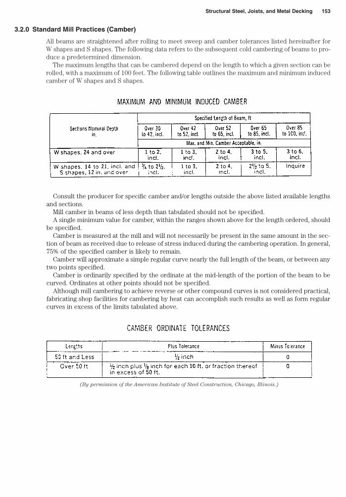
3.2.0 Standard Mill Practices (Camber)
All beams are straightened after rolling to meet sweep and camber tolerances listed hereinafter forW shapes and S shapes. The following data refers to the subsequent cold cambering of beams to pro-duce a predetermined dimension.
The maximum lengths that can be cambered depend on the length to which a given section can berolled, with a maximum of 100 feet. The following table outlines the maximum and minimum inducedcamber of W shapes and S shapes.
Structural Steel, Joists, and Metal Decking 153
Consult the producer for specific camber and/or lengths outside the above listed available lengthsand sections.
Mill camber in beams of less depth than tabulated should not be specified.A single minimum value for camber, within the ranges shown above for the length ordered, should
be specified.Camber is measured at the mill and will not necessarily be present in the same amount in the sec-
tion of beam as received due to release of stress induced during the cambering operation. In general,75% of the specified camber is likely to remain.
Camber will approximate a simple regular curve nearly the full length of the beam, or between anytwo points specified.
Camber is ordinarily specified by the ordinate at the mid-length of the portion of the beam to becurved. Ordinates at other points should not be specified.
Although mill cambering to achieve reverse or other compound curves is not considered practical,fabricating shop facilities for cambering by heat can accomplish such results as well as form regularcurves in excess of the limits tabulated above.
(By permission of the American Institute of Steel Construction, Chicago, Illinois.)
154 Section 3
(By permission of the American Institute of Steel Construction, Chicago, Illinois.)
3.2.1 Standard Mill Practices (“W” Shape Tolerances)
Structural Steel, Joists, and Metal Decking 155
(By permission of the American Institute of Steel Construction, Chicago, Illinois.)
3.3.0 Suggested Beam Framing Details
156 Section 3
(By permission of the American Institute of Steel Construction, Chicago, Illinois.)
3.3.1 Suggested Column Base Plate Details
Structural Steel, Joists, and Metal Decking 157
(By permission of the American Institute of Steel Construction, Chicago, Illinois.)
158 Section 3
(By permission from The McGraw-Hill Co., Structural Details Manual, David R. Williams.)
(By permission from The McGraw-Hill Co., Structural Details Manual, David R. Williams.)
3.3.4 Typical Braced Bay—Detail Connections
160 Section 3
(By permission from The McGraw-Hill Co., Structural Details Manual, David R. Williams.)
3.3.5 Typical Braced Bay—Other Detail Connections
(By permission from The McGraw-Hill Co., Structural Details Manual, David R. Williams.)
161
3.3.6 Typical Channel Girt Connection
162 Section 3
(By permission from The McGraw-Hill Co., Structural Details Manual, David R. Williams.)
Figure 3.3.7 Typical Roof Opening Detail
Structural Steel, Joists, and Metal Decking 163
(By permission from The McGraw-Hill Co., Structural Details Manual, David R. Williams.)
3.3.8 Typical LH–Joist Connection Details
164 Section 3
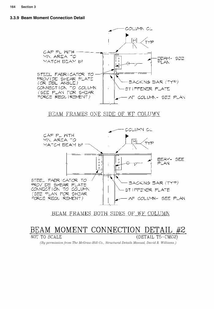
(By permission from The McGraw-Hill Co., Structural Details Manual, David R. Williams.)
3.3.9 Beam Moment Connection Detail
3.4.0 Welded Joints—Standard Symbols
Structural Steel, Joists, and Metal Decking 165
(By permission of the American Institute of Steel Construction, Chicago, Illinois.)
166 Section 3
(By permission from Steel Deck Institute, Fox River Grove, Illinois.)
3.4.1 Tensile Strength of Puddle Welds
3.5.0 Threaded Fasteners—Bolt Head Shapes
Structural Steel, Joists, and Metal Decking 167
(By permission of the American Institute of Steel Construction, Chicago, Illinois.)
3.5.1 Threaded Fasteners—Weight of Bolts
168 Section 3
(By permission of the American Institute of Steel Construction, Chicago, Illinois.)
3.5.2 Threaded Fasteners—Weight of ASTM A325 or A490 Bolts
Structural Steel, Joists, and Metal Decking 169
(By permission of the American Institute of Steel Construction, Chicago, Illinois.)
Heavy Hex Structural Bolts with Heavy Hex Nuts in Pounds per 100
170 Section 3
(By permission of Nucor Fastener division of Nucor Corp., St. Joe, Indiana.)
3.5.3 Properties of Heavy Hex Nuts and Identifying Marks
Structural Steel, Joists, and Metal Decking 171
(By permission of Nucor Fastener division of Nucor Corp., St. Joe, Indiana.)
3.5.4 Bolt Diameters and Standard Hole Dimensions
172 Section 3
(By permission of Nucor Fastener division of Nucor Corp., St. Joe, Indiana.)
3.5.5 Capscrews/Bolts/Heavy Hex Nut Identifying Marks
Structural Steel, Joists, and Metal Decking 173
(By permission of Nucor Fastener division of Nucor Corp., St. Joe, Indiana.)
3.5.6 Dimensions of Finished Hex Nuts
(By permission of Nucor Fastener division of Nucor Corp., St. Joe, Indiana.)
174
3.5.7 Dimensions of Finished Hex Bolts
3.5.8 Tension Control (TC) Bolt Installation Procedures
Tru-Tension Fasteners are designed to be installed with various types of lightweight portable electricwrenches specifically intended for use with this style of structural fastener. They can be utilized forany applications where A325 and A490 bolts are specified. The installation tool has an inner socket,which engages the spline tip of the bolt spline, and when the tension is sufficient in the fastener, thespline tip simply twists off, leaving the tightened bolt correctly installed in the connection.
Structural Steel, Joists, and Metal Decking 175
(By permission of Nucor Fastener division of Nucor Corp., St. Joe, Indiana.)


![DNVGL-RU-SHIP Pt.4 Ch.6 Piping systems · PDF fileThe requirements cover the design of the scrubber unit, ... 3.2.3, 3.3.1, 3.3.8, 3.3.9, 3.4.10, 3.4.11 and Table 3] and Sec.10 ...](https://static.documents.pub/doc/80x56/5aaa58c47f8b9a86188def01/dnvgl-ru-ship-pt4-ch6-piping-systems-requirements-cover-the-design-of-the-scrubber.jpg)


