STRUCTURE, PROPERTIES, AND PERFORMANCE OF INORGANIC-FILLED SEPARATORS
R. Waterhouse, J. Emanuel, J. Frenzel, D. Lee, S. Peddini, Y. Patil, G. Fraser-Bell, and R.W. Pekala The 29th International Battery Seminar & Exhibit, March 12 – 15, 2012
COMPETING SEPARATOR TECHNOLOGIES
Separator Design Company Limitations / Challenges
Biaxially oriented PE separators Tonen
SK
Asahi
135 C flow, 180 max meltdown
Residual stress in melt
Polymer oxidation
High melting point polymers
PP/PE/PP
PVDF
Coextrusion
PI, PEEK
crosslinked systems
Celgard
Ube
Tonen
Porous Power
155- 165 C flow
Residual stress in melt
Polymer oxidation
Processing difficulties with high temp or crosslinkable polymers
Heat resistant layers
Inorganic coatings
Electrodes
Separator
Matsushita
LG
High coating precision required
Controlled particle size distribution
PE layer shrinkage
Ceramic separators
PET inner layer
Al2O3/SiO2 coating
Evonik Poor mechanical properties (i.e., brittle)
Dusting
Expensive
Nanofiber-based separators
Electrospinning
Polyimide
Dupont Throughput
Expensive
Highly Filled separators ENTEK
Asahi
Sufficiently high loading levels
Residual stress in polymer matrix
2
ENTEK APPROACH
Overcome high temperature thermal shrinkage and mechanical integrity
challenges in large format Li-ion batteries via
(1) sufficiently high, inorganic filler loading levels
(2) polymer crosslinking, and/or
(3) heat treatment above polymer melting point
Investigate highly filled systems using UHMWPE as polymer matrix
3
Challenges
can thickness range be achieved ?
what fillers ?
what loading level ?
does annealing / heat treatment work ?
INORGANIC / CERAMIC FILLERS
5
Filler Type / Grade
Surface Treatment availability
Commercial Concerns Technical Concerns
Alumina fumed high cost Al2O3 reduction at anode calcined activated
Silica fumed
gas generation from reaction of SiO2 with HF precipitated SiO2 reduction at anode
Titania fumed lithium intercalation pigment
Calcium Carbonate
ground gas generation from reaction of CaCO3 with HF precipitated
SILICA VS ALUMINA
Skeletal density
SiO2 2.15 g/cc
Al2O3 3.96 g/cc
Fumed structures generally have lower fractal dimension than precipitated structures
Loading level to achieve 3-dimensional inorganic network depends upon both the filler type and its dimensionality
filler / polymer > 1
69.1 wt % silica
80.5 wt % alumina
6
SEM --- MD FRACTURE
12
Lower cost, activated alumina particles do not breakdown and disperse uniformly during the extrusion process.
Activated Alumina particles
PATHWAYS TO OPTIMAL FILLER DISPERSION
Filler selection
High surface area
Low fractal dimension (wispy)
weak inter-aggregate bonds
surface chemistry
Screw configuration
Aggressive
Pre-dispersion
Wet milling
15
EXCELLENT DIMENSIONAL STABILITY
16
USABC Goal : < 5% shrinkage at 200 C
Achieved with more than one formulations and different inorganic fillers
Silica filled separator
Roll ID Base roll Filler:PE Thickness (avg) 200° C Shrinkage % Gurley Puncture
µm MD XMD sec/10ml gf /25 u
DY110217.002 59 2.1 18.7 5.87 4 6.8 280
DY110221.001 263 2.3 25.3 4.67 4 7.8 230
DY110301.003 260 2.3 23.8 4.2 3.5 7.2 224
DY110302.002 260 2.3 23.3 4 3.5 7.4 244
DY110303.002 260 2.3 25.1 4.5 3.7 7.6 214
DY110218.002 64 2.6 21.3 6.5 2.67 5.3 192
Alumina filled separator
Roll ID Base roll Filler:PE Thickness (avg) 200° C Shrinkage % Gurley Puncture
µm MD XMD sec/10ml gf /25 u
DY110131.025 202 2.7 25.4 5 1 12.7 391
DY110214.003 202 2.7 20.8 6.33 2.5 12 386
BENCHMARKING AGAINST OTHER INORGANIC SEPARATORS
Alumina or silica coated onto PET carrier
Ceramic coating on polyolefin separator
17
SEPARION BEFORE & AFTER SHRINKAGE AT 200 C
18
Before 200 C Shrink Test
After 200 C Shrink Test
< 5% MD & TD shrinkage
BENCHMARKING FILLED SEPARATOR VS. COATED SEPARATOR
12 micron PE separator dip coated with an Al2O3/PVA solution.
Varying amount of alumina coating applied
19
COATED SEPARATOR SHRINKAGE
21
Loading A Loading B
Loading C
Loading A Loading B
Loading C
< 5% MD & TD shrinkage only achieved when coat wt. exceeded 33%
ALUMINA-COATED SEPARATOR AFTER 200 C OVEN TEST
22
Filler penetration inside the separator could be responsible for improved thermal stability.
Filler rich surface can interact with electrodes.
PE only
PE + Al2O3
PE + Al2O3
EXCEPTIONALLY LOW IMPEDANCE
Roll ID Base roll Filler Filler:PE Thickness Areal
Resistance Resistivity MacMullin Number
Microns Ω-cm² Ω-cm
Inorganic Filled Separators
DY110217.002 59 Silica 2.1 19 0.59 308 2.6
DY110224.002 263 Silica 2.3 23.8 0.63 266 2.2
DY110224.004 261 Silica 2.3 22.8 0.85 373 3.1
DY110303.001 260 Silica 2.3 24.1 0.59 247 2.1
DY110218.002 64 Silica 2.6 20.5 0.48 232 1.9
DY110131.025 202 Alumina 2.7 25.9 1.06 410 3.4
DY110214.003 202 Alumina 2.7 22.3 0.88 396 3.3
Unfilled Separators
Teklon HPIP Unfilled 25 2.15 869 7.2
Teklon Gold LP Unfilled 12 1.85 1460 12.2
Coated Unfilled Separator
Coated Teklon Alumina 14 2.4 1668 13.9
Rapid wetting with electrolyte
Enhanced power capability and low temperature performance
23
USABC Goal : MacMullin # < 11
Achieved with all formulations
INORGANIC FILLER IMPROVES SEPARATOR WETTING
0
2
4
6
8
10
12
14
16
0 10 20 30 40 50 60 70
Wic
kin
g D
ista
nce
(m
m)
Wicking Time (min.)
Wicking Rate: PR57, 2.1:1, silica-filled
1
2
3
4
0
2
4
6
8
10
12
14
16
0 20 40 60 80 100 120
Wic
kin
g H
eig
ht
(mm
)Wicking Time (min.)
Separator Wicking Test
Microporous PE PR61 silica-filled
24
Wicking rate measurements are repeatable.
Silica-filled separator rises at over twice the rate of porous PE.
Wicking height at 30 minutes
Separator suspended in electrolyte in a graduated cylinder
Build 18650 Cells American Lithium Energy Corp. • 10 cells for each separator
formulation
Initial Performance Characterization 8 cells
• 1C discharge, room temp • 1C discharge, -30°C • HPPC, room temp.
Calendar Life Test 60°C, 100% SOC
• 4 cells each formulation •Repeat RPT every 4 wks
Cycle Life Test Room Temp., 1C with 2C pulse
• 4 cells each formulation
7-day OCV screening test
2 cells reserved for future tests.
CELL TESTING
25
0
0.2
0.4
0.6
0.8
1
1.2
1.4
1.6
0 200 400 600 800 1000 1200 1400 1600 1800 2000
Dis
char
ge C
apac
ity (A
H)
Cycle Number
18650 Cycle Capacity: Microporous PE Controls
00901001201380% Cap.
Average Fade = -24.6%
INORGANIC FILLER IMPROVES CELL CYCLE LIFE
26
• 18650 cells: NMC/graphite • Room temperature, 100% DOD, 1C rate. • Control cells: 80% of initial capacity at 1000-1100 cycles. • Cells with silica-filled separator: 80% of initial capacity at 1600-2000 cycles.
Silica-filled separator increases cell cycle life compared to control (MP). More uniform electrolyte distribution more uniform electrode utilization.
0
0.2
0.4
0.6
0.8
1
1.2
1.4
1.6
0 200 400 600 800 1000 1200 1400 1600 1800 2000
Dis
char
ge C
apac
ity (A
H)
Cycle Number
18650 Cycle Capacity: Silica-filled Separators
silica 19silica 21silica 23silica 2480%Series2
2000 cyclesAverage Fade (3 cells) = -20.2%
Microporous PE Silica-filled separator
CYCLE LIFE OF CELLS WITH DIFFERENT INORGANIC-FILLED SEPARATORS
0.0
0.2
0.4
0.6
0.8
1.0
1.2
1.4
1.6
0 200 400 600 800 1000 1200 1400 1600 1800 2000 2200
Disc
harg
e Cap
acity
(AH)
Cycle Number
Separator filler: fumed silica
1600 cycles
Average Fade = -22.5%
0.0
0.2
0.4
0.6
0.8
1.0
1.2
1.4
1.6
0 200 400 600 800 1000 1200 1400 1600 1800 2000 2200
Dis
char
ge C
apac
ity (A
H)
Cycle Number
Separator filler: fumed silica + alumina
2000 cycles
Average Fade = -21.3%
27
All four groups have better cycle life than the control. No filler combination appears better than precipitated silica.
0.0
0.2
0.4
0.6
0.8
1.0
1.2
1.4
1.6
0 200 400 600 800 1000 1200 1400 1600 1800 2000 2200
Dis
char
ge C
apac
ity (A
H)
Cycle Number
Separator filler: alumina
2200 cycles Average Fade = -20.9%
0.0
0.2
0.4
0.6
0.8
1.0
1.2
1.4
1.6
0 200 400 600 800 1000 1200 1400 1600 1800 2000 2200
Dis
char
ge C
apac
ity (A
H)
Cycle Number
Separator filler: alumina + titania
Cycle 1700 Average Fade = -23.7%
INORGANIC FILLER REDUCES SELF-DISCHARGE
3.7
3.75
3.8
3.85
3.9
3.95
4
4.05
4.1
4.15
4.2
0 20 40 60 80 100 120 140 160 180
Ope
n C
ircui
t Vol
tage
Days on Test
60°C Storage Test - Teklon Control: Cell OCV
US0005US0006US0007US0008
3.7
3.75
3.8
3.85
3.9
3.95
4
4.05
4.1
4.15
4.2
0 20 40 60 80 100 120 140 160 180
Ope
n C
ircui
t Vol
tage
Days on Test
60°C Storage Test - Silica-filled: Cell OCV
US0015US0016US0017US0018
28
• 60°C Storage Test: Fully charged (4.2V), OCV checked daily, test every 4 weeks.
Silica-filled separator reduces self discharge and capacity loss.
Microporous PE Silica-filled separator
SUMMARY
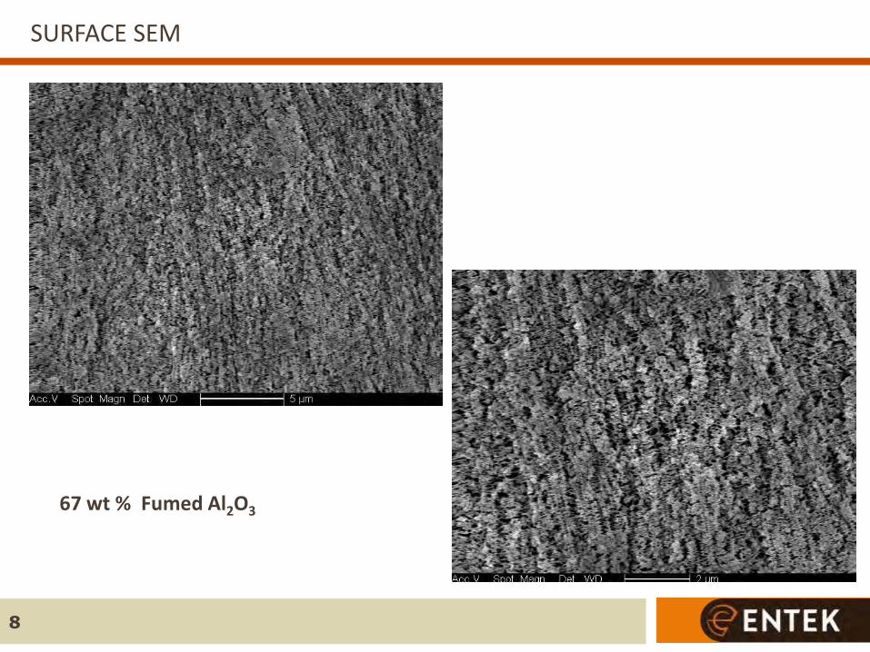
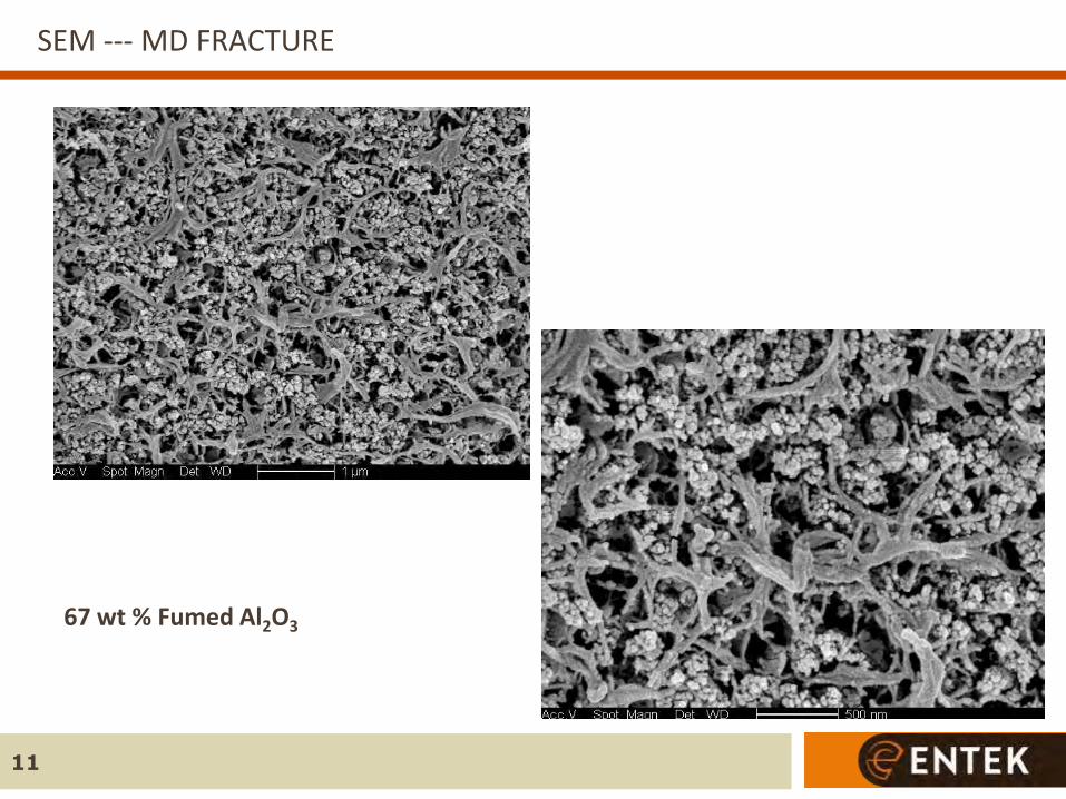
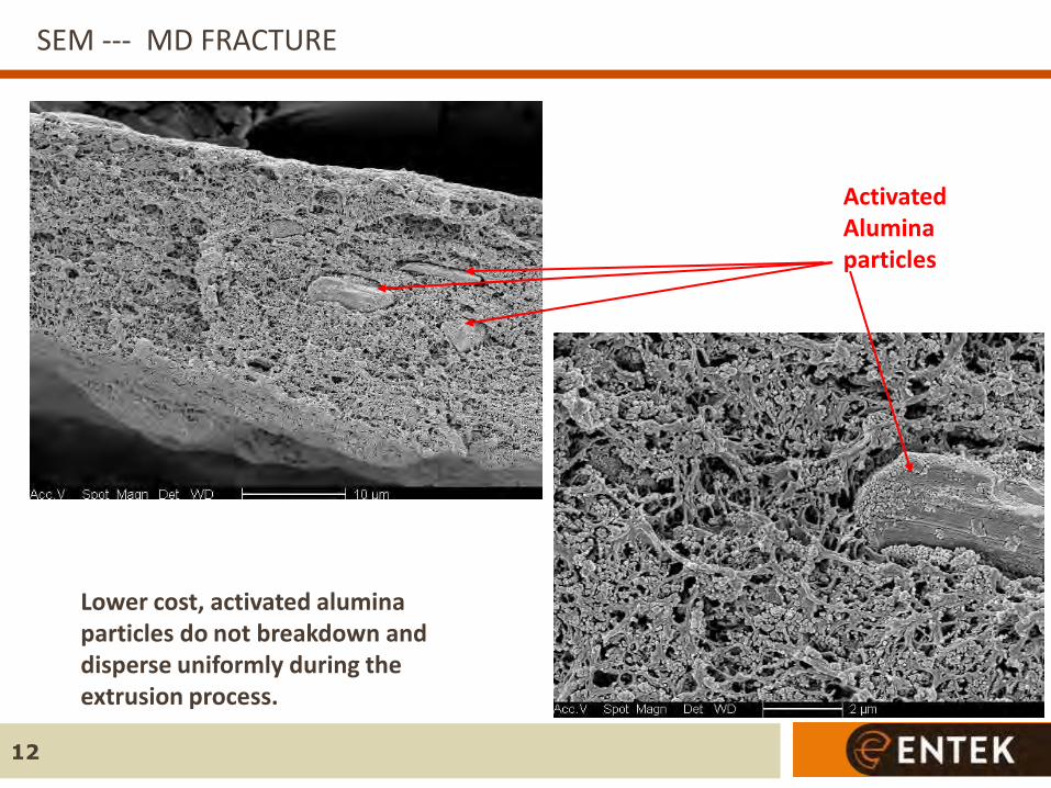
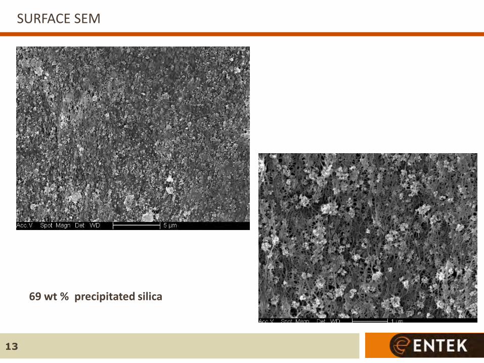
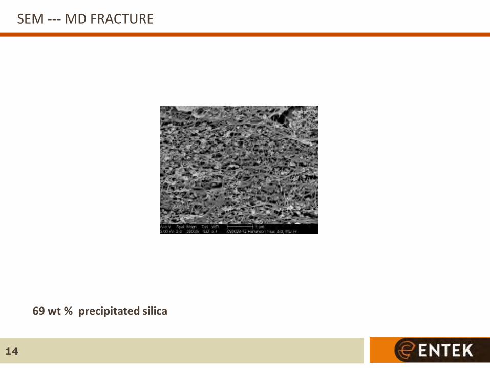
Free-standing, dimensionally stable, inorganic-filled separators were produced
from precipitated silica and fumed alumina using UHMWPE as a binder
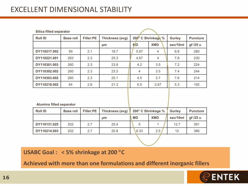
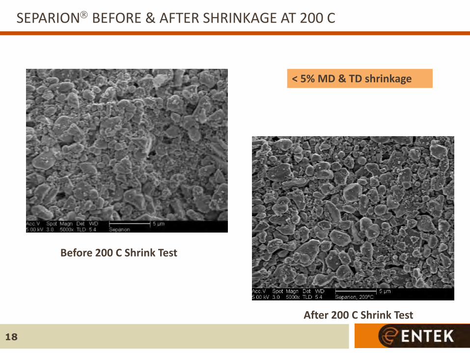
These inorganic-filled separators exhibited < 5% shrinkage in both MD and TD after 1 hour at 200 C.
Inorganic-filled separators have excellent wettability and ultralow impedance (MacMullin number < 3) that allows for high power capability and low temperature performance
18650 cells with inorganic-filled separators show good performance compared to control cells with a microporous polyethylene separator. Improved cycle life
Lower self discharge
Higher rate capability
Preliminary cost models suggest that silica-filled separators can approach target price; however, cell drying step is likely required to gain performance benefits
29
ACKNOWLEDGMENT
30
This material is based upon work supported by the Department of Energy, National Energy Technology Laboratory under Award Number DE-FC26-05NT42403 with the United States Advanced Battery Consortium (USABC). Disclaimer: “This report was prepared as an account of work sponsored by an agency of the United States Government and USABC. Neither the USABC, the United States Government nor any agency thereof, nor any of their employees, makes any warranty, express or implied, or assumes any legal liability or responsibility for the accuracy, completeness, or usefulness of any information, apparatus, product, or process disclosed, or represents that its use would not infringe privately owned rights. The views and opinions of authors expressed herein do not necessarily state or reflect those of the United States Government or any agency thereof, or those of USABC.”