Structured Annotations for 2D-to-3D Modeling Yotam Gingold (New York University / JST ERATO) Takeo Igarashi (University of Tokyo / JST ERATO) Denis Zorin (New York University) 1 In this talk, “Structured Annotations for 2D-to-3D Modeling,” I will present an interface for quickly turning 2D drawings into undetailed 3D geometry. This is joint work with Takeo Igarashi and Denis Zorin.
Transcript
Structured Annotations for 2D-to-3D ModelingYotam Gingold (New York University / JST ERATO)Takeo Igarashi (University of Tokyo / JST ERATO)Denis Zorin (New York University)
1In this talk, “Structured Annotations for 2D-to-3D Modeling,” I will present an interface for quickly turning 2D drawings into undetailed 3D geometry.
This is joint work with Takeo Igarashi and Denis Zorin.
Pencil and Paper Sketches
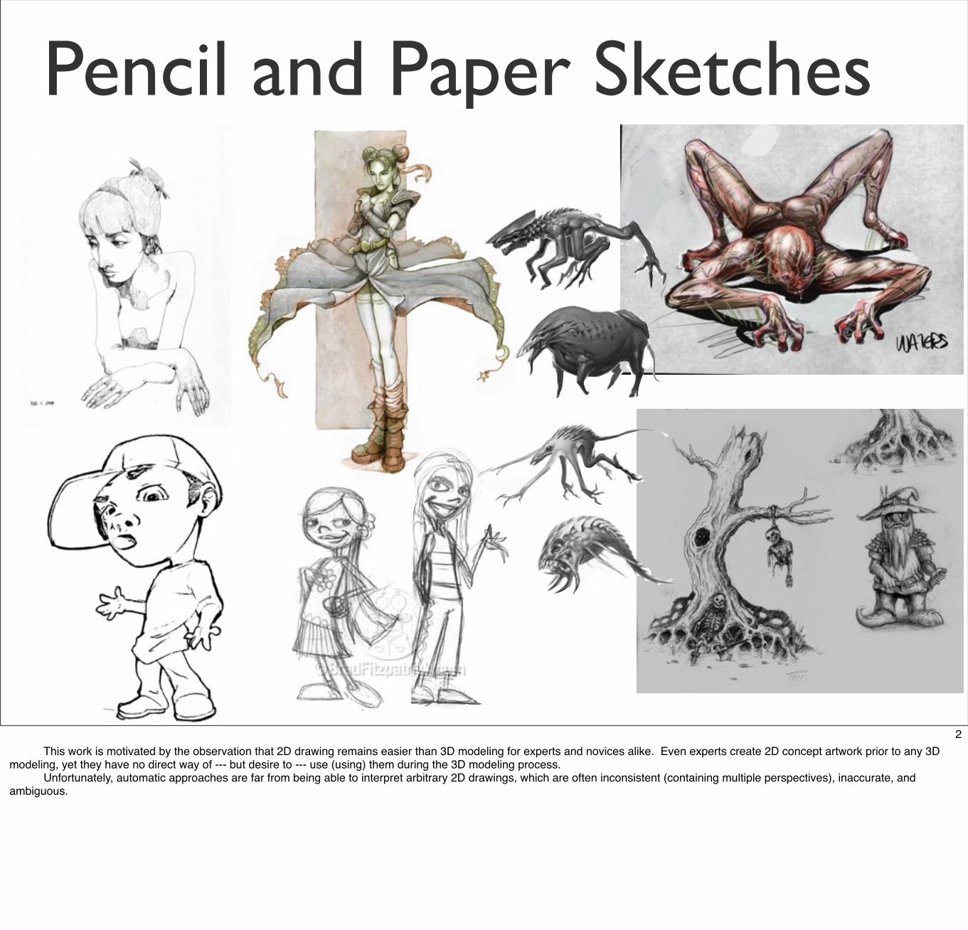
2 This work is motivated by the observation that 2D drawing remains easier than 3D modeling for experts and novices alike. Even experts create 2D concept artwork prior to any 3D modeling, yet they have no direct way of --- but desire to --- use (using) them during the 3D modeling process. Unfortunately, automatic approaches are far from being able to interpret arbitrary 2D drawings, which are often inconsistent (containing multiple perspectives), inaccurate, and ambiguous.
Traditional Expert Systems
[Maya] [Mudbox]
[Thormälen and Seidel 2008]
Concept artwork plays no direct role
3In traditional, professional 3D modeling tools, concept artwork plays no direct role. At most, designers will draw axis-aligned sketches, and place them in the 3D scene for reference. [Tsang et al. 2004] and [Thormälen and Seidel 2008] introduced techniques based on axis-aligned images.
Novice Systems ( )
Tedd
y [I
gara
shi e
t al
. 199
9]
Shap
eSho
p[S
chm
idt
et a
l. 20
05-8
]
See [Olsen et al. 2008] for a recent survey.
Fibe
rMes
h [N
eale
n et
al.
2007
]
Spor
e [M
axis
200
8]
Can’t trace a guide image
4 There are a variety of novice systems, as well. These systems make it possible for novices to create 3D models, and they make modeling easier for experts, as well. Sketch-Based Modeling is a popular approach for creating free-form models. In this approach, users typically sketch silhouette curves from different views. This leverages users' 2D drawing skills. However, the view matters --- it determines the sketched strokeʼs plane --- so users must rotate to a “good” view before every stroke. As a result, the workflow takes the form of Sketch-Rotate-Sketch. In our evaluations, we found that this constant rotation is difficult for novice users. (An evaluation of a pure 3D manipulation task in [Schmidt et al. 2008] reached a similar conclusion.) If youʼre not working from a guide image and the shape is entirely in your head, then this workflow is a good one (novice rotation difficulties notwithstanding). Otherwise, sketching the shape from novel views makes it difficult to model from a guide image. Examples of this approach include Teddy, FiberMesh, and ShapeShop.
5This brings us to our approach, which is most similar in spirit to the Single-View Modeling approaches of [Zhang et al. 2001] and [Wu et al. 2007]. We want to allow users to model from guide images, such as these. The idea is to leverage the userʼs interpretive abilities to describe the shape.
<click>The user does this by placing shape primitives and annotations that look like this. The primitives convey local shape information, and the annotations specify geometric relationships, such as same lengths and angles, symmetries, and attachments.
<click>The 3D model is created from these primitives and annotations; we donʼt consult the guide image.
Note that in this interpretive process, we do not expect that users have a consistent 3D mental model of the shape; we aim to create plausible, reasonable quality 3D models from a user's possibly inconsistent input.
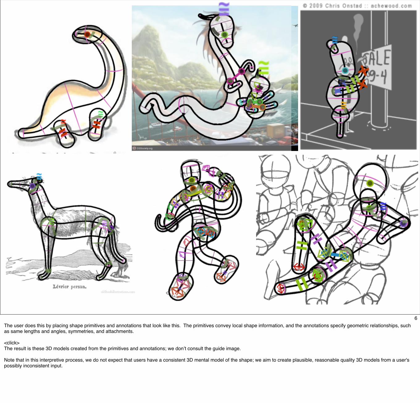
6The user does this by placing shape primitives and annotations that look like this. The primitives convey local shape information, and the annotations specify geometric relationships, such as same lengths and angles, symmetries, and attachments.
<click>The result is these 3D models created from the primitives and annotations; we donʼt consult the guide image.
Note that in this interpretive process, we do not expect that users have a consistent 3D mental model of the shape; we aim to create plausible, reasonable quality 3D models from a user's possibly inconsistent input.
7The result is these 3D models created from the primitives and annotations; we donʼt consult the guide image.
Note that in this interpretive process, we do not expect that users have a consistent 3D mental model of the shape; we aim to create plausible, reasonable quality 3D models from a user's possibly inconsistent input.
Overview
Interface
Results & 2 User Studies
Implementation Details
Conclusion
8In this talk, I will present our interface, results, and two user studies before discussing implementation details.
Inspiration
[Vilppu 1997]
[Bla
ir 1
994]
2D Drawing Approaches
9The inspiration for our approach comes from 2D drawing approaches, which are based on composing a model out of primitive shapes --- or decomposing, if drawing reality. In our approach, we reconcile the primitives' “local” shape information with the semantic information from annotations to create a plausible, globally consistent 3D model.
Even poor quality drawings are understandable by humans, and are able to convey local shape information, as well as semantic information about a model.
PrimitivesGeneralized Cylinders & Ellipsoids
10<video> In our interface, the user loads an image and proceeds to place 2D primitives overtop.Our primitives are generalized cylinders and ellipsoids.
All editing operations are performed in the 2D view on the left; the view on the right displays the resulting 3D model.
Primitives
Generalized Cylinder Ellipsoid
11
Users manipulate these primitives with a variety of handles.
Here are the generalized cylinder’s handles.
Primitive: Generalized Cylinder
12<video><demo>
A generalized cylinder is created with a spine stroke. Its cross sections can be tilted out of the view plane. Cross sections' radii can be adjusted, as well. There are handles to provide control over its end caps.
The cylinder's generalized symmetry plane, called its symmetry sheet, can also be adjusted. This affects symmetry-related annotations, which weʼll see shortly.
The user can also draw or choose a non-circular cross section at any point along the spine.
Finally, users can oversketch or drag to deform the spine.
Primitive: Ellipsoid
13<video><demo>
An ellipsoid is created by drawing its silhouette. Ellipsoids have handles for tilting the long axis out of the view plane, and for controlling the radius of the two shorter axes. (We constrain ellipsoids to have circular cross sections [perpendicular to the long axis].) While an ellipsoid could be thought of as a special case of a generalized cylinder, the set of suitable handles is different.
Connection curve
Mirror
Alignment
AnnotationsSame-length
Same-tilt
Same-scale
z
y
z
y
=~
14Users annotate these primitives in a variety of ways.Several annotations mark equal geometric measurements; the rest mark connections between primitives and symmetries.
Here are examples scenarios for these annotations.
Annotations: Connection Curves
15Connection curves attach one primitive to another. The surfaces are placed in depth so that they intersect along the connection curve.
Annotations: Mirror
16Mirror annotations duplicate and reflect a primitive across another.
Annotations: Alignment
17An alignment annotation can be used to center one primitive on another's symmetry plane or sheet.
Annotations: Alignment
18They can also be used to align a pair of primitives across another's symmetry sheet.
Annotations: Same-length
19We also support a variety of congruency annotations.
Here, the user creates two cylinders and marks them as having the same length.
Note that the primitives in the annotation view do not change; in general, primitives are placed to match a guide image.
Annotations: Same-scale
20In this example, the user marks two cross sections as having the same scale.
Annotations: Same-tilt
21The user can also mark two tilted cross sections of a cylinder as having the same tilt angles with respect to the view plane.
Demo
Guide image [Vilppu 1997]
22<video><demo>
Here is an example modeling session, sped up five times. We designed the interface to work similar to 2D drawing programs; all manipulations are performed in 2D and directly manipulate curves in 2D; for example, cross section and silhouette curves. There are no hidden parameters. Annotations are important because a drawing may contain global inconsistencies. With the semantic information of annotations, we can rectify the primitives to produce a plausible 3D model.
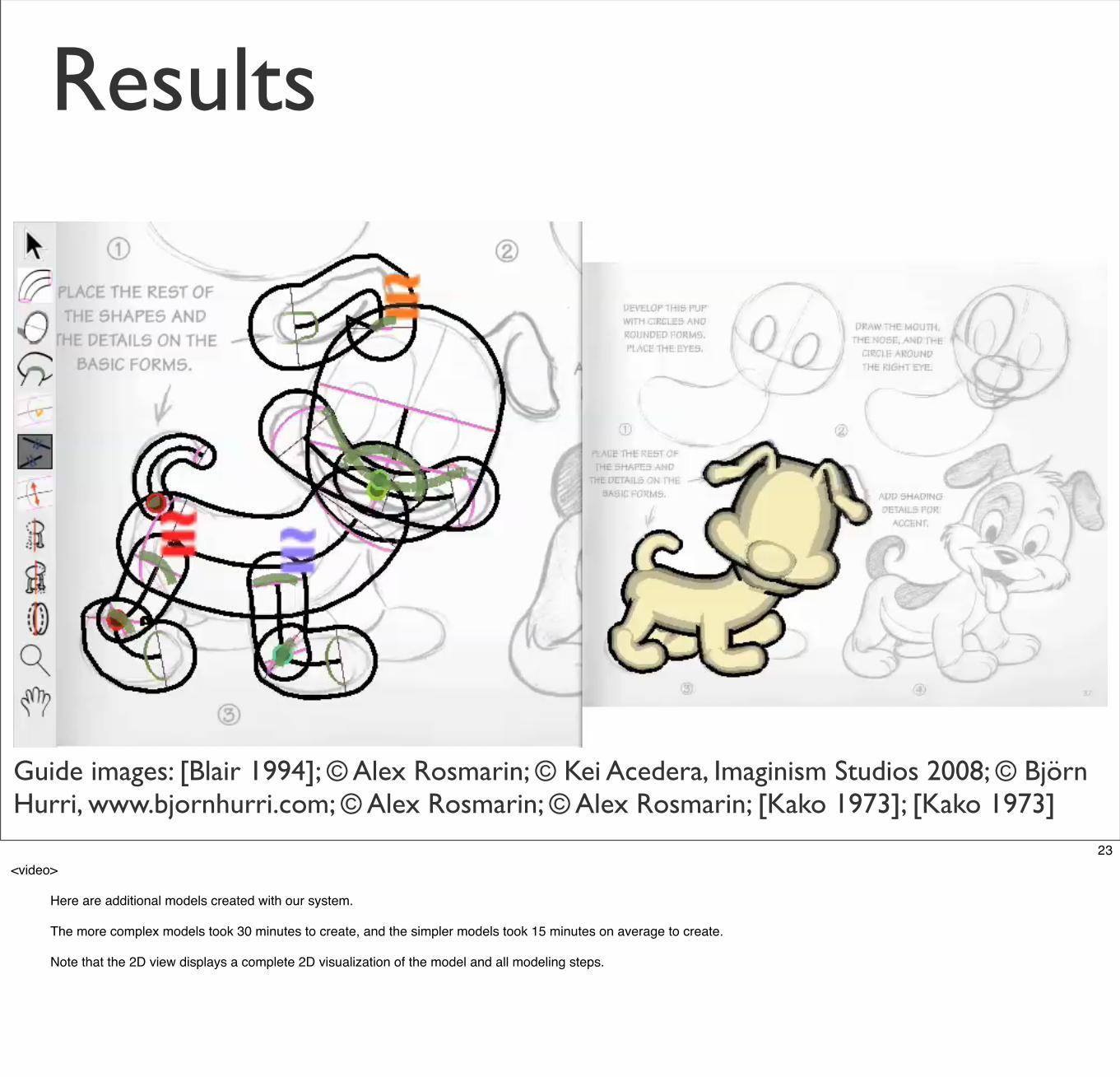
Here are additional models created with our system. The more complex models took 30 minutes to create, and the simpler models took 15 minutes on average to create. Note that the 2D view displays a complete 2D visualization of the model and all modeling steps.
Here are additional models created with our system. The more complex models took 30 minutes to create, and the simpler models took 15 minutes on average to create. Note that the 2D view displays a complete 2D visualization of the model and all modeling steps.
2 User Studies
24We performed two informal user studies: an unguided study and a comparison study.
Informal Study
25<video>
These models were created by first-time users as part of an unguided, informal user study. Users chose or drew their own guide images. Even users unfamiliar with 3D manipulation felt comfortable with the tilting interface. Objectively these users were slower, though. Some users tweaked manually instead of using annotations “properly”. Since modeling is done in a 2D view, some users (fairly) expect the interface to act like a 2D drawing interface, which has been our goal.
Comparison Study
Create 3D model from this dog illustration
15 minutes of training
7 users, none had 3D modeling experience
Our system FiberMesh [Nealen et al. 2007]
vs.
26 We also performed a comparison study between our system and FiberMesh [Nealen et al. 2007]. FiberMesh is a recent sketch-based modeling system employing the sketch-rotate-sketch paradigm. FiberMesh was modified to display an underlying guide image and to have a side-by-side second view. Users were asked to create a 3D model from this 2D dog illustration (preceded by 15 minutes of training), and to work until satisfied. Half were randomly assigned to use our system first.
There were 7 subjects. Most had some casual 2D artistic experience, were familiar with 3D manipulation concepts, and had no 3D modeling experience.
Comparison StudyFi
berM
esh
[Nea
len
et a
l. 20
07]
Our
sys
tem
preferred
avg:
31 m
ins
avg:
29 m
ins
27 Average time-to-satisfaction (or frustration, depending) was 29 minutes in our system and 31 minutes in FiberMesh.
Several subjects noted their satisfaction at being able to directly trace silhouettes in FiberMesh, but found the depth placement and orientation difficult to control for all but the initial shape. Multiple subjects remarked that the symmetry-related annotations were a great benefit and that they would have liked to have had them in FiberMesh. Overall, five subjects preferred our system (outlined in red), one preferred FiberMesh, and one had no preference. While this experiment is biased towards our problem statement, we believe that modeling from a guide image is an important workflow that has been largely neglected in the literature.
Implementation
28I will now present a few implementation details.
Implementation: Generalized Cylinder
t = 0
t = 1scale(t)
tilt(t)
• Parametric
•
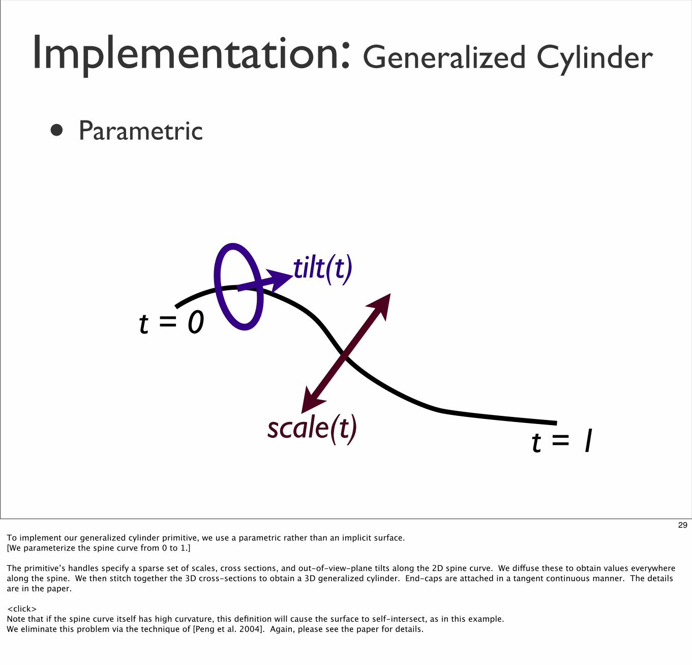
29To implement our generalized cylinder primitive, we use a parametric rather than an implicit surface.[We parameterize the spine curve from 0 to 1.]
The primitive’s handles specify a sparse set of scales, cross sections, and out-of-view-plane tilts along the 2D spine curve. We diffuse these to obtain values everywhere along the spine. We then stitch together the 3D cross-sections to obtain a 3D generalized cylinder. End-caps are attached in a tangent continuous manner. The details are in the paper.
<click>Note that if the spine curve itself has high curvature, this definition will cause the surface to self-intersect, as in this example.We eliminate this problem via the technique of [Peng et al. 2004]. Again, please see the paper for details.
Implementation: Generalized Cylinder
• Parametric
• [Peng et al. 2004] to avoid self-intersections
30Note that if the spine curve itself has high curvature, this definition will cause the surface to self-intersect, as in this example.<click>We eliminate this problem via the technique of [Peng et al. 2004]. Again, please see the paper for details.
Implementation: Generalized Cylinder
• Parametric
• [Peng et al. 2004] to avoid self-intersections
31We eliminate this problem via the technique of [Peng et al. 2004]. Again, please see the paper for details.
Implementation: Annotations
• Annotations take precedence over primitives’ handles
• Annotations are mostly independent, so we apply them procedurally, not via optimization:
z
y
z
y
=~
32Annotations may conflict with parameters specified by primitives’ handles. Because annotations are based on semantic information the user knows to be true, annotations take precedence.
Annotations are largely independent of each other, so we apply them procedurally rather than via optimization.
Implementation: Connection Curves
• Solve for depth offset between the two primitives
d
33Connection curves attach one primitive to another. To be specific, the connection curve should project onto both surfaces identically. We solve for a single value, the depth offset d between the two surfaces, which minimizes the error in a least-squares sense. Dragging a connection curve is implemented similarly; the location of the mouse provides the only equation in the least-squares system.
Please see the paper for details on applying the other annotations.
Contributions
34To summarize our contributions: We have presented an interface for modeling by “describing” an existing 2D image with primitives and annotations. This approach augments the pencil-and-paper workflow often preferred by designers. Our interface is usable by novices, including those with poor drawing skills. The resulting model is structured and contains semantic information. For example, the skeletons can be used for animation, symmetry can be maintained when when painting or refinement sculpting, and the parts segmentation can be used by deformation algorithms. Our approach naturally provide a complete 2D visualization of the 3D model and its structure. This makes it easy to explain and learn how to create a given model.
Contributions
• Interface for modeling by “describing” an existing 2D image with primitives and annotations.
• Usable by novices, including those with poor drawing skills.
• Resulting model is structured and contains semantic information.
• Naturally provide a complete 2D visualization of the 3D model and its structure.
34To summarize our contributions: We have presented an interface for modeling by “describing” an existing 2D image with primitives and annotations. This approach augments the pencil-and-paper workflow often preferred by designers. Our interface is usable by novices, including those with poor drawing skills. The resulting model is structured and contains semantic information. For example, the skeletons can be used for animation, symmetry can be maintained when when painting or refinement sculpting, and the parts segmentation can be used by deformation algorithms. Our approach naturally provide a complete 2D visualization of the 3D model and its structure. This makes it easy to explain and learn how to create a given model.
Limitations
[Sch
mid
t et
al.
2009
b]
35Our approach has several limitations.
It is limited in the range of models that can be produced. - Our approach cannot handle man-made objects; surfaces with edges; and thin, flat areas. - It is also not the right tool for adding fine-scale details; rather the resulting undetailed model can be refined in a 3D sculpting tool such as Z-Brush or Mudbox.
Our approach canʼt be used for certain drawings, such as this hippopotamus on the right. - When a drawingʼs point-of-view aligns with primitivesʼ spines or long axes, they are projected to (or nearly to) a single point.
We cannot handle cycles of connection curves, such as a character with a hand on his hip or holding something with both hands.
Limitations
• Limited range of models [Sch
mid
t et
al.
2009
b]
35Our approach has several limitations.
It is limited in the range of models that can be produced. - Our approach cannot handle man-made objects; surfaces with edges; and thin, flat areas. - It is also not the right tool for adding fine-scale details; rather the resulting undetailed model can be refined in a 3D sculpting tool such as Z-Brush or Mudbox.
Our approach canʼt be used for certain drawings, such as this hippopotamus on the right. - When a drawingʼs point-of-view aligns with primitivesʼ spines or long axes, they are projected to (or nearly to) a single point.
We cannot handle cycles of connection curves, such as a character with a hand on his hip or holding something with both hands.
Limitations
• Limited range of models
• Can’t be used for certain drawings
[Sch
mid
t et
al.
2009
b]
35Our approach has several limitations.
It is limited in the range of models that can be produced. - Our approach cannot handle man-made objects; surfaces with edges; and thin, flat areas. - It is also not the right tool for adding fine-scale details; rather the resulting undetailed model can be refined in a 3D sculpting tool such as Z-Brush or Mudbox.
Our approach canʼt be used for certain drawings, such as this hippopotamus on the right. - When a drawingʼs point-of-view aligns with primitivesʼ spines or long axes, they are projected to (or nearly to) a single point.
We cannot handle cycles of connection curves, such as a character with a hand on his hip or holding something with both hands.
Limitations
• Limited range of models
• Can’t be used for certain drawings
• No cycles of connection curves
[Sch
mid
t et
al.
2009
b]
35Our approach has several limitations.
It is limited in the range of models that can be produced. - Our approach cannot handle man-made objects; surfaces with edges; and thin, flat areas. - It is also not the right tool for adding fine-scale details; rather the resulting undetailed model can be refined in a 3D sculpting tool such as Z-Brush or Mudbox.
Our approach canʼt be used for certain drawings, such as this hippopotamus on the right. - When a drawingʼs point-of-view aligns with primitivesʼ spines or long axes, they are projected to (or nearly to) a single point.
We cannot handle cycles of connection curves, such as a character with a hand on his hip or holding something with both hands.
Future Work
36In the future we would like to add
more primitives and annotations. - We would like to handle surfaces with edges and thin, flat areas. [The Vilppu Drawing Manual contains useful a box-like primitive.] - We could add annotations describing the range of motion of joints for animation or material rigidity for deformation. - Finally, our primitives and annotations are very low-level; they can be grouped together in useful ways, such as a bundle of primitives and annotations to represent a human or a quadruped.
We would like to use the underlying guide image, as in [Tsang et al. 2004]. We could - snap primitives to edges in the image and - extract colors or texture from the image.
In some cases, oblique projections may allow for a less surprising 3D interpretation of user input. The literature on human perception, including a study published this year by [Schmidt et al 2009], describe consistent perceptual biases.
Finally, a comprehensive user study comparing our system to many other systems, with a large number of users at multiple skill levels, remains to be performed.
Future Work
• More primitives and annotations
• Use the underlying guide image [Tsang et al. 2004]
• Different camera models
• Comprehensive user study
36In the future we would like to add
more primitives and annotations. - We would like to handle surfaces with edges and thin, flat areas. [The Vilppu Drawing Manual contains useful a box-like primitive.] - We could add annotations describing the range of motion of joints for animation or material rigidity for deformation. - Finally, our primitives and annotations are very low-level; they can be grouped together in useful ways, such as a bundle of primitives and annotations to represent a human or a quadruped.
We would like to use the underlying guide image, as in [Tsang et al. 2004]. We could - snap primitives to edges in the image and - extract colors or texture from the image.
In some cases, oblique projections may allow for a less surprising 3D interpretation of user input. The literature on human perception, including a study published this year by [Schmidt et al 2009], describe consistent perceptual biases.
Finally, a comprehensive user study comparing our system to many other systems, with a large number of users at multiple skill levels, remains to be performed.
37I would like to thank Alex Rosmarin and the artists who generously gave us permission to use their artwork. I would also like to thank our user testers.