The “hole” is greater than the sum of the parts “Stucco is only one small piece of a very complex puzzle. The composite of any construction relies on the syner- gism of all the pieces working together. The stucco is not the cause of a win- dow or roof leak, or the reason the sheathing and studs are rotting in walls. We can prove these facts every time.” -Steven Pedracine, Executive Direc- tor, Minnesota Lath & Plaster Bureau A Brief History Lesson Portland cement plaster, otherwise known as stucco has been used with “Promoting the Industry Since 1953” STUCCO IN RESIDENTIAL CONSTRUCTION great success in the Twin Cities for over 110 years! The history does not begin there however. Long before the invention of portland cement, poz- zolana stucco was used on some of man’s oldest and most widely recog- nized wonders of the world: The Aq- ueducts in Rome, the Colosseum, the Forum are just some examples. In Europe lime stucco can be seen on almost everything. In the United States, Benjamin Henry Latrobe at the behest of Thomas Jefferson de- (Continued on page 3) Moisture Intrusion: Stucco problem or construction problem? A publication of the...
Transcript
The “hole” is greater than the sum of the parts
“Stucco is only one small piece of a very complex puzzle. The composite of any construction relies on the syner-gism of all the pieces working together. The stucco is not the cause of a win-dow or roof leak, or the reason the sheathing and studs are rotting in walls. We can prove these facts every time.” -Steven Pedracine, Executive Di rec-tor, Minnesota Lath & Plaster Bureau
A Brief History Lesson Portland cement plaster, otherwise known as stucco has been used with
“Promoting the Industry Since 1953”
STUCCO IN RESIDENTIAL CONSTRUCTION
great success in the Twin Cities for over 110 years! The history does not begin there however. Long before the invention of portland cement, poz-zolana stucco was used on some of man’s oldest and most widely recog-nized wonders of the world: The Aq-ueducts in Rome, the Colosseum, the Forum are just some examples. In Europe lime stucco can be seen on almost everything. In the United States, Benjamin Henry Latrobe at the behest of Thomas Jefferson de-
(Continued on page 3)
Moisture Intrusion: Stucco problem or construction problem?
A publication of the...
The text, drawings and related notes contained herein are typical of stucco installations in Minne-sota. Please see the Uniform Building Code for specific requirements. Examples illustrated are not called out in the code in all cases. This guide contains general information on stucco installation and related materials. It is provided as a guide only and is not intended for any specific con-struction project. The Minnesota Lath and Plaster Bureau makes no express or implied warranty or guarantee of the techniques, construction methods, materials and details identified herein, nor does it assume any liability for the use of this information. It is the sole responsibility of any architectural or construction industry professional to apply their pro-fessional knowledge in utilizing the information con-tained in this publication. To the best of our knowledge, this information is correct and up to date as of the July 2000 printing. To ensure that you have the most current version please contact the Minnesota Lath & Plaster Bu-reau. Reproduction of this material is not permitted without the expressed written permission of the Minnesota Lath and Plaster Bureau.
Disclaimer Minnesota Lath and Plaster Bureau 820 Transfer Road St. Paul, MN 55114
The Minnesota Lath and Plaster Bureau has promoted the industry since 1953. It is recognized as an education and technical spokesman for the plastering industry. It provides services to architects, the con-struction community and the public on a variety of matters relating to the plastering trades.
• Introduction……………….. • Disclaimer ………………... • Selecting Sheathing …….. • Building Paper……………. • Metal Lath…………………. • Weep Screeds……………. • Other Terminations………. • Local Suppliers…………... • Roof Line Issues Chimneys...………………… Roof / Wall Intersections…. Kick-out Flashings…………. Soffits……………………….. • Windows…………………….
signed many important Washington landmarks with stucco as the cladding. In this century who can define modern architecture better than Frank Lloyd Wright who favored a smooth portland cement stucco finish on much of his prairie and contemporary style work. Yes, stucco is as enduring as time itself. So why are so many fingers pointing at stucco as the reason for moisture intrusion issues? The answer is not a simple one, however we can state unequivocally that construction has evolved dramatically in just the past 10-15 years.
The Mc Mansion Phenomenon How has construction evolved? Look around you; have you seen any convent i ona l “Raised Ranches” or “Ramblers” going up lately? Good economic times bring bigger more expensive homes. “Mc Mansion” is the buzz-word today, with multiple steeply pitched roofs and dormers, large expanses of glass, decks and impressive projecting facades with more angles than Isosceles ever thought about. This extends to the inside environment where we cannot live without our vaulted ceilings, skylights, garden tubs and indirect can light-ing. Buildings today are much more energy effi-cient. This has been a marked improvement in keeping us warm in the winter and cool in the summer. But these improvements in comfort seem to come at the cost of durability in the overall construction. Homes built today are much tighter. We use more insulation, more thermally efficient windows, more caulk, more glue, better vapor barriers, building wraps, air tight outlet boxes etc. The result is fewer holes and lower air exchange between the inside and the outside. Without adequate ventilation this has created an interior environment with more concentrated pollutants and elevated moisture levels. And, If improperly addressed,
this often results in condensation problems, mold and decay growing in and on walls, ice dams and wood rot among other maladies.
The Tip of the Iceberg The problems we are seeing are not confined to dwellings with stucco as the cladding. Brick, stone, vinyl, wood, wood composites, shakes, cement board, metal, have all been affected. Because stucco is monolithic (it has no seams) it appears the phenomenon has defined itself more quickly than in other claddings. Stucco is in fact better than many conventionally clad homes because it keeps the building more com-fortable by slowing down air infiltration. This same benefit however, can create a wall that is slower to dry when it does become wet from condensation, leaking windows or improperly
flashed details. So why can’t we build
like we use to? This is a frequently asked
question. But we live in an age of enlightened concern for conserving our natural resources. We could go back to building inefficient, drafty homes, but it would be at the cost of higher en-ergy consumption and less comfort. This would obviously be a step in the wrong direction. Complex problem straightforward solution
Okay, so what really is the problem? What we are seeing is the beginning of a construction problem, not a stucco problem. What can we do? We can have a better understanding of how building materials integrate with one an-other. The answer is communication. For it’s small part in this complex puzzle, the Minnesota Lath and Plaster Bureau presents this handbook as a proactive approach to this end.
“If you can’t figure out how to flash it, should you really be
building it?”
3
Note: The intent of any of the details that fol-low is to keep water out. There are other op-tions that may be equal or even more effec-tive.
Sheathing performs the function of sub-strate back-up to the stucco. When choosing a sheathing substrate for stucco, considera-tion should be given to the product’s vapor permeability (ability to pass moisture in its gaseous state), it’s ability to withstand expo-sure to moisture and it’s structural character-istics. Each sheathing product has their own set of attributes and deficiencies. For this reason special considerations are necessary for the proper installation of each. Types of Sheathings Available: Ligno-Cellulosic Fiber Board a.k.a. Bildrite lists a vapor permeability rating of 30 Perms. Exterior Gypsum Sheathing (5/8”) typically has a vapor permeance value of 40 Perms. Another gypsum product often seen on com-mercial buildings is Georgia-Pacific’s Dens-Glass Gold . This product offers supe-rior moisture resistance with a glass mat sur-facing and comes with a six month in-place open exposure warranty. United States Gypsum also promotes a similar product called Fiberock Aqua-Tough which comes with a one year in place open exposure war-ranty . Wood sheathings available are Exposure 1 Plywood, Exposure 1 Oriented Strand Board and Exterior Grade Plywood . Struc-turally, wood sheathing panels are the pre-ferred sheathing in the residential market be-cause they provide the best shear value and racking resistance. Wood sheathing is semi-permeable. Under normal relative humidity various plywood species (3/8”) has a per-meance range of .45-1.43 perms and OSB (7/16”) .91 Perms. However the permeance increases by a factor of 10 when the humid-ity is increased to 90%.
Installation Comments: The Engineered Wood Association (APA) and International Bildrite, Inc recommend that their sheathings be spaced at all edges and ends 1/8” between adjacent pan-els. This is to minimize the effects of swelling of the sheathing due to moisture. For more infor-mation contact APA or Bildrite. Those phone numbers are listed on page 23.
“Wood structural panels used as wall sheathing are susceptible to fungal decay (rot) if exposed to moisture content, generally considered to be greater than 20% for an extended period of time. These panels are manu-factured with adhesive systems that withstand extreme moisture conditions in uncovered conditions such as when fully exposed during construction. How ever when covered as they are in wall systems, moisture in-trusion can lead to conditions where the panels cannot dry. Extended periods where the panels remain at ex-cessive levels of moisture can lead to fungal deteriora-tion of the wood itself. All untreated wood in such con-dition, panels and studs, is prone to decay… Therefore it is important to protect wood components from pro-longed exposure to moisture. The correct use of build-ing paper and flashing will help to provide protection from moisture.”
The Engineered Wood Association
Bulletin TB-202
Selecting Sheathing
0.80 0.91
30.00
23.00
28.00
40.00
0.00
5.00
10.00
15.00
20.00
25.00
30.00
35.00
40.00
45.00
1. PLYWOOD(3/8")
1. OSB (7/16") 2. BILDRITE(25/32")
3. DENS-GLASSGOLD (1/2") (5/8" = 12)
4. FIBEROCKAQUA TOUGH
(1/2") (5/8" = 35)
3. GYPSUMSHEATHING
(1/2")
PERMS (DRY CUP METHOD)
COMPARING SHEATHING PERMEANCE
4
Building Paper UBC 2506.4
Building Paper: Building Paper is a weather re-sistive barrier that is applied over the sheathing prior to the installation of the stucco. It’s pur-pose is to keep the sheathing dry, which will minimize cracking in the stucco. Requirements: The Uniform Building Code re-quires two layers of building paper classified as Grade “D” paper over wood and wood compos-ite sheathings. This includes not only plywood and OSB, but Bildrite as well. 15# felt cannot be used as a substitute. Sheathing panels that are approved water-repellent panels may not require building paper. Gypsum sheathing sometimes falls into this category, however the manufacturer of the prod-uct should be consulted before proceeding. The Minnesota Lath and Plaster Bureau suggests one layer of building paper over gypsum sheath-ing panels. Installation Comments: Building paper can be applied over wood sheathed substrates in dou-ble thickness rolls. There is no regulation that
states that two layers must be applied in con-secutive applications. As required by code the building paper shall be applied horizontally, with the upper layer overlapping the lower layer not less than 2”. Where vertical joints oc-cur the paper should be lapped not less than 6”. The Minnesota Lath and Plaster Bureau recommends that the building paper be wrapped continuously through both internal and external corners. Also, as per the Minne-sota Energy Code, breaches in the building paper created by ducts, electrical service mud rings, pipes, etc., should be cut with a sharp knife to fit snugly, then weatherproofed with sealant or adhesive membrane tape before the lath and stucco is installed. Tyvek StuccoWrap®: A recent development in housewrap products is StuccoWrap. This spunbonded polyolefin membrane is a recognized alternative to Grade D building paper. According to the manufacturer, StuccoWrap offers hydration advantages in curing stucco with better crack resistance. For
more information contact the Tyvek distributor listed on page 8.
“Type 15 or 15# felt is not Grade D
Building Paper”
Metal Lath UBC 2506
Metal Lath: Due to the varying geographic loca-tions where the Uniform Building Code is en-forced a variety of laths are accepted. Based upon local practice the Minnesota Lath & Plas-ter Bureau recommends 3.4# self furring galva-nized metal lath. Attachment: Code requires that the corrosion resistant “fasteners for metal lath be spaced 6” on center (maximum) at supports”. In this con-text “supports” means framing. Fasteners must penetrate wood framing a minimum of ¾”. There
has been much controversy lately about the impact of over fastening into the sheathing between wood framing. Theories include the belief that fasteners coming out the backside of the sheathing are magnets for frost in the winter months. While we can appreciate the concern that this theory embraces, we must point out that frost is the result of condensation. Conden-sation occurs when water vapor reaches a saturation (dew) point within the wall. Mois-ture can only condense on solid surfaces (it cannot condense in air and it is unlikely to
(Continued on page 5)
5
(Continued from page 5)
condense in the fiberglass batt insulation) so the inside surface of the sheathing is the only place for this phenomenon to likely occur. This would happen regardless as to whether fasteners are poking through the back side of the sheathing or not. It is then the consensus among many plastering professionals and the Minnesota Lath and Plaster Bureau, that a few extra fasteners between the framing supports is not detrimental to the overall wall assembly. However, liberal use of fasteners should be avoided. As another option, additional fasteners can be used that do not penetrate the entire thickness of the sheathing. Lath shall be ap-plied with the long dimension at right angles to the supports. Ends of the lath shall be staggered to adjacent pieces applied above and below it. Metal lath shall be lapped ½” at sides and 1” at ends. For more information refer to section 2505.3 of the Uniform Building Code. Corners: UBC 2506.5 states “Where no external corner reinforcement is used, lath shall be furred out and carried around corners at least one support on frame construction.” To provide extra rein-forcement and a straighter more uniform corner Stockton Wire Products, Corner Aid (or equivalent) can be used at these locations.
Weep Screeds
According to code, “A minimum 0.019-inch (No. 26 galvanized sheet gage) corrosion - resistant weep screed with a minimum vertical at-tachment flange of 3.5 inches shall be provided at or below the founda-tion plate line on all exterior stud walls. The screed shall be placed a minimum of 4 inches above the earth or 2 inches above paved ar-eas and shall be of a type that will allow trapped water to drain to the exterior of the building. The weather resistive barrier (Grade “D” building paper) shall lap the attachment flange, and the exterior lath shall cover and terminate on the attach-ment flange of the screed.”
For ease of installation, weep screeds are generally installed so that the back attachment flange is fastened to the plate. For aesthetic reasons, some applications may require the stucco to con-tinue down over an exposed foundation. In this situation building officials have expressly stated that the building paper must extend onto the foundation wall and lap onto the attachment flange of the weep screed as previously mentioned. A recent development to the weep screed compo-nent is a bottom flange that still provides the weep function, but allows stucco to be applied di-rectly to the foundation wall. Consult your local building official to determine acceptability.
UBC 2506.5
6
Stucco sometimes is used only on the front side of a home and another clad-ding used on the other three. In this de-tail vinyl siding is illustrated. Vinyl siding is often installed without a secondary weather barrier. If however one is installed behind the vinyl, it should lap under the building paper be-neath the stucco no less than 6”. To transition this change in claddings, it is important that the building paper used behind the stucco laps over the back leg of the casing bead used to ter-minate the stucco. Because vinyl moves from thermal expansion and contraction, it is impor-tant to seal the juncture between the stucco and vinyl with backer rod and low modulus elas-tomeric sealant.
Other Common Terminations
Combining stucco with another cladding such as brick adds aes-thetic interest. The transition be-tween the two claddings can be-come awkward because the brick is generally offset from the stucco. The best way to handle this transi-tion is to provide a flashing that is set in place before the plasterer installs the stucco. Note that the building paper laps over the back leg of the flashing for positive drainage
Transition @ Brick
Vertical Transition @ Vinyl Siding
Plan Section
7
A frequently seen detail on entries is stucco columns on top of concrete stoops. With this type of construction comes the prospect of water finding it’s way behind the interface where the column construction meets the concrete stoop. One of the better ways to avoid water intrusion issues at these locations is simply to raise the construction above the level of the concrete stoop with a small concrete pad or curb. The building paper is then lapped over the concrete pad for positive drainage and the stucco is terminated with a casing/ stop bead. A small gap is suggested between the casing bead and the concrete stoop for thermal movement , to minimize corrosion of the stop bead and as a capillary break from standing water.
Local Material Suppliers
RESOURCE SUPPLY, INC. 8823 Zealand Ave. N, Suite "P" Brooklyn Park, MN 55445 Tel: (763) 425-7863 (800) 238-1647 Fax: (763) 425-9286 E-Mail: [email protected] SNOW LARSON, INC. 1925 Oakcrest Avenue Roseville, MN 55113 Tel: (651) 636-0630 Fax: (651) 636-4855 E-Mail: [email protected] Website: www.snowlarson.com SIMPLEX Construction Supplies, Inc. 5610 International Parkway Minneapolis, MN 55428 Phone: 763-533-9210 Fax: 763-533-4686 E-mail: [email protected]
HEDBERG AGGREGATES 1205 Nathan Lane Plymouth, MN 55441 Tel: (763) 545-4400 Fax: (763) 545-7121 E-Mail: [email protected] Website: www.shadeslanding.com/hedberg/ TAMARACK MATERIALS 9300 James Ave. S. Bloomington, MN 55431 Tel: (952) 888-5556 Fax: (952) 888-4030 E-Mail: [email protected] THE LUTZ COMPANY 6311 Cambridge Street St. Louis Park, MN 55416 Tel: (952) 929-4309 Fax: (952) 929-8391
TK PRODUCTS 11400 W. 47th Street Minnetonka, MN 55343 Tel: (952) 938-7223 (800) 441-2129 Fax: (952) 938-8084 E-Mail: [email protected] WINROC 5262 Glenbrook Ave. N. Oakdale, MN 55128 Tel: (651) 777-8222 Fax: (651) 777-4375 Website: www.winroc.com J. B. O’MEARA COMPANY Dupont Tyvek StuccoWrap® 901 E. Cliff Rd. Burnsville, MN 55337 Tel: (952) 882-2423 Toll Free: (800) 352-2832 Fax: (952) 890-2103
Column on Concrete Stoop
8
Stucco has often been used in the past to weatherproof and decorate concrete block chim-neys. Appearance is deceiving in today’s construction how-ever, as the chimney is often composed of a fire rated metal flue with a framed chase en-closed with sheathing. The out-ward appearance is similar to what we have seen in the past, but the construction of these enclosures is a critical aspect to moisture infiltration into the assembly. Chimney Cap: From the top of the chimney a metal cover is installed to cover the chase opening. This is the only defense of the enclosure to the elements. It should be watertight and ex-tend over the top edge of the stucco. Wind driven rain can find it’s way between the interface of the stucco and the cap flashing, so it is suggested that this interface be sealed with a good quality elastomeric sealant. Cricket: Sometimes referred to as a saddle, a cricket is installed on the high side of the chimney to divert water away from the construction. Crickets are especially critical on today’s homes where roof lines are steeply pitched. To perform optimally, they must be properly flashed and weather tight.
Roof Line Issues Chimneys
Roof rakes at stucco walls: Dormers and chimneys that ex-tend up from roofs are not unusual challenges in today’s homes built with multiple roof lines, however, attention must be paid to these locations. Roofing Felt: It is good practice to base flash prior to the in-stallation of metal flashing. This is accomplished by simply ex-tending the felt or adhesive backed membrane slightly up the vertical wall (see illustration).
Roof / Wall Intersections
Installed by Roofer 9
Sealant installed by General Contractor
Flashing: Step flashing is preferred over continuous flashing along a roof rake be-cause it is interlaced with the shingles for positive drainage away from the wall / roof interface. Kick-out Diverter: A critical location where moisture entry can do considerable damage is where a lower roof cornice stops in the middle of a stucco wall. Kick-outs should be fabricated with watertight seems and be big and broad enough to handle water run-off from a variety of roof pitches. Another criti-cal element is the use of gutters to evacuate the water away from these sensitive loca-tions. There are several local materials suppliers that now offer these kick-outs in both a left an right hand versions (contact one of the suppliers listed on page 8 , for further information). Install-ing the kick-out after the installation of the shingles is a very difficult procedure for the lather or stucco contractor to perform. For this reason it should be coordinated so that the kick-out is in-stalled by the roofer as the shingles are being laid up.
Installing Building Paper: Proper building paper installation should be left to the stucco contractor. Building paper should be installed to lap over the back flange of the kick-out and the step flashings for positive drainage. Care should be taken to cut the paper tightly around the kick flange. The subsequent cut should be mended with adhesive backed membrane flash-ing material as illustrated
Stucco Termination: Over the years the preferred method of termi-
nating the stucco above a roof was to simply die it into the shingles. Another option has been to provide a stop bead above the shingles. Either method has its advantages and draw backs. Dying the stucco into
the shingles: While this option is aesthetically a more pleas-ing termination it should be considered with an eye towards the future. Because when the shingles must be replaced, they will have to be cut out very carefully along the edge of the stucco. Stopping the stucco with a casing bead: This termination will make it easy to remove and replace shingles at a later time, but it is often aesthetically objectionable because it ex-poses the flashing above the roof line. Caution must also be taken in positioning the attachment flange on the wall, so that no fasteners puncture the wall flashing.
Kick-Out Flashing
Installed by Roofer
By Stucco Contractor
10
110o
5" MIN.
8" MIN.
WATER T IGHTSEAMS
5" MIN.
Soffits: Minnesota Energy Code Rules 7670, 7672
Soffits: The State Building Official in a letter to Building Officials dated 11-15-99, states that “Paper must be installed on the entire wall, including within the soffits framing. While this requirement has not been expressly writ-ten into the UBC Code there is reference to it in the Minnesota Energy Code, Rules Chapter 7670 page 20 , Subparagraph 6, item D , #2. Coordinating: Often times when the stucco contractor is scheduled to do his job, the soffit is already in place. If this is the case, the gen-eral contractor should coordinate this aspect of the job, so that this area has the building paper is in place prior to the soffit installation. The plas-terer should then be able to easily tie his building paper installation into the paper above for posi-tive drainage.
UBC 1402.2
11
Windows The Uniform Building Code States “ Exterior open-ings exposed to the weather shall be flashed in such a manner as to make them weather proof.” With re-spect to windows and doors, it is incumbent upon the general contractor to ensure that this action is car-ried out before the window or door unit is placed in the opening. Failure to perform this task can result in moisture intrusion, mold, rot and ultimately structural damage. Flashing performs by allowing moisture to pass to the exterior plane of the cladding (stucco). The Min-nesota Lath & Plaster Bureau suggests that the best option for flashing a window is a pan flashing. Pan flashing is generally fabricated from break formed corrosion resistant sheet metal or PVC plastic. It is placed on the sill of the rough opening, prior to the insertion of the window. Moisture that penetrates through the window construction is then safely exited over the exterior surface of the stucco. This type of construction is common practice on commercial projects but also would be effective in residential applications, especially if the window is suspect or has no slope for positive drain-
(Continued on page 12)
(Continued from page 11)
age at the sill (see detail page 11). The limitation to the practice however is the bottom nailing fin, which must be removed to accept the pan flashing. Removal of the bottom fin may result in the window manufacturer voiding any warranty that may come with the window. Other consid-eration must be given to sizing the rough opening accordingly to accommodate the extra build-up of materials. As an option a pan flashing can be installed prior to step 4 in the procedure that follows. Short of in-stalling a pan flashing under the window the next best alternative is the procedure illustrated in the following pages. Before proceeding, please consult the window manufacturer for specific installation re-quirements.
• Cut a 9” wide strip of Grade “D” Building Paper approximately 24” longer than the width of the rough window opening.
• Under the window sill, staple the pa-per along the top edge only. Allow approximately 12” of paper to ex-tend past the opening on either side as shown.
Step 1
Step 2 • Corners are exceptionally
vulnerable to small holes that can allow moisture into the construction.
• Use either of the two meth-ods shown to completely encase the corner.
12
By Window Installer
By Window Installer
Note: Consult manufacturer of membrane material to determine if product is appropriate and durable for its intended use.
Step 3
• Cut a piece of 6” adhesive backed membrane 8” longer than the win-dow opening. (Note: Use 8” wide membrane for 2”x 6” construction).
• Make a 2” cut in the membrane, 4” in from the ends as shown.
• Peel backing off of membrane and install as shown. Note that 4” of the membrane rides up onto the rough jamb and folds out and over the face of the sheathing. The remaining 2” at the sill, folds down and sticks over the previously installed building pa-per.
Step 4
• NOTE: IF METAL OR PVC PAN FLASHING IS TO BE USED, IN-STALL NOW.
• Cut Grade “D” Building Paper ap-proximately 13” wide x 24” longer than the height of the window opening.
• Cut out corners of building paper as shown.
• Fold and install building paper to cover the rough jamb and fold out onto the face of the sheathing. Staple into place.
By Window Installer
By Window Installer
13
Step 5 • Per window manufacturers in-
structions, apply a continuous bead of compatible sealant at the top and sides of the win-dow opening or along the back of the nailing fin immediately before the installation of the window.
• Install the window following window manufacturers fasten-ing requirements.
• If nailing fins on the window are not self sealing, install sealant at the flange, as required by the window manufacturer.
• If the window does not come with an integral drip cap head flashing, one should be purchased from the manufacturer, or vendor as recom-mended by the manufacturer.
• Carefully follow window manufactur-ers instructions for installation of the drip cap flashing.
• Note: Some manufacturers require a continuous bead of sealant under both the vertical and horizontal legs of the drip cap flashing before in-stallation.
By Window Installer
Step 6
14
By Window Installer
Step 8
Step 7
• On wood sheathed construction the Uniform Building Code (UBC) requires two layers of Grade “D” building paper. It is acceptable to apply the building paper in a dou-ble ply roll.
• According to code, the building pa-per must be installed shingle style so that each subsequent horizontal course overlaps the previous a minimum of 2”. Vertical joints should be lapped 6”.
• Note that the two plies of building paper below the sill are tucked un-der the building paper installed be-fore the window.
• At the jambs, install the double ply roll so that it laps over the nailing fin and abuts the window jamb.
• Continue installing courses beyond the height of the window unit as shown.
• If nailing fins do not have a con-
tinuous seal around the corners, install gaskets that come with the window.
• Carefully follow window manufac-turer’s instructions for the installa-tion of any gasket materials or necessary sealants that must be applied for proper installation of the window unit.
15
By Stucco Contractor
By Window Installer
• Install vertical strips of adhe-sive membrane over the building paper and nailing fins to fold up and onto the window jamb. Membrane should extend past the nail-ing fins at the head and sill.
• Install another layer of mem-brane flashing horizontally over the back flange of the drip cap. Membrane flashing at the head should extend and cover the membrane pre-viously installed at the jambs.
• If the drip cap is integral to the window unit, apply the membrane flashing over the head similar to what has been described above.
Step 9
By Stucco Contractor
• Size and cut the double roll of building paper to bridge over the opening between the building paper at the sides.
• Note that the building paper ex-tends past the paper previously installed at the jambs by 6”. This is to provide positive drainage and conform to code require-ments.
Step 10
16
By Stucco Contractor
Note: The intent of any of these details is to keep water out. There are other options that may be equal or even more effective.
• Window frames expand and contract due to temperature changes. Some, much more than others. This may re-sult in significant water intrusion where the stucco meets the window.
• To compensate for this expansion and contraction, some window manufactur-ers require a space between the clad-ding and the window frame. The subse-quent void between the window and stucco is later filled with a bond breaker and low modulus elastomeric sealant.
• At the jambs and sill install stop beads 3/8” away from the window frame. In-stall flush at the drip cap flashing. Care should be taken to avoid fastening the stop bead into the nailing fin. Fastening into the nailing fin will cause cracking in the stucco.
• Care should be taken to ensure that the interface of the stop beads and the drip cap flashing at the jamb is properly sealed against moisture intrusion.
Stopping Stucco Around Windows
Selecting Sealants When selecting sealants consideration should be given to the products movement capabili-ties, durability and compatibility with other ma-terials. For these reasons the manufacturer of these products should be consulted. Sealant is not a maintenance free material. Depending on the type, sealants may have to be checked regularly to ensure optimum per-formance. Generally, sealant manufacturers provide de-tailed written instruction for the proper installa-tion of their materials. This often is quite in-volved in the description of mixing, use of bond breaker materials, primers, shape, thick-ness and size of the sealant bead. Failure to follow these instructions often will void any in-tended warranty.
There are several types of sealants currently available: Polyurethanes are perhaps the most adaptable product with respect to color matching, but they are not as elastic as others and some-times require mixing multiple components on site. Silicones provide the best elasticity properties and are longer lasting but have a limited color palette. A more recent innovation in sealant tech-nology is silyl-terminated sealants. For more information on sealants contact the manufacturers listed on page 23.
Optional
Sealant by General Contractor
17
Step 2
Step 1
Deck Attachment
• Position and attach building paper at location where deck header will be at-tached.
• Position and attach corro-sion resistant metal flashing so that horizontal leg aligns with final position of the bot-tom of the deck header.
• Fabricate corrosion resis-tant end dam. Position and attach at the end of the flashing.
• Fabricate a corner patch from adhesive backed membrane and install at in-ternal corner of end dam.
• Seal small hole in corner of end dam with elastomeric sealant for weather tight seal.
• Install adhesive backed self healing membrane over the metal flashing. Height of membrane should equal height of deck header.
By General Contractor
By General Contractor 18
Step 3 • Install Grade “D” Building
Paper over membrane for positive drainage.
• Seal interface of building paper and back of end dam with membrane.
• It is suggested that small saw kerfs (1/8” deep max.) be put into the bot-tom of the deck header to optimize positive drain-age.
• Deck header can be in-stalled now. Provide cor-rosion resistant washers or pipe sleeve spacer (no more than 1/2” long) be-tween deck header and wall construction for posi-tive drainage behind the deck. Be sure to seal the penetration of the fastener
By General Contractor
By Stucco Contractor
19
• Install casing bead around perimeter of opening prior to installa-tion of lath and stucco. Note that a space is pro-vided for bond breaker and elastomeric sealant at end dam.
Step 4
Note: The intent of any of these details is to keep wa-ter out. There are other op-tions that may be equal or even more effective.
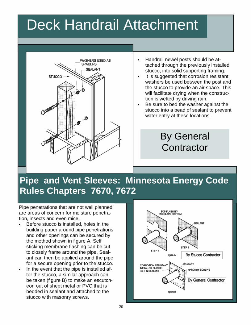
Deck Handrail Attachment
• Handrail newel posts should be at-tached through the previously installed stucco, into solid supporting framing.
• It is suggested that corrosion resistant washers be used between the post and the stucco to provide an air space. This will facilitate drying when the construc-tion is wetted by driving rain.
• Be sure to bed the washer against the stucco into a bead of sealant to prevent water entry at these locations.
Pipe penetrations that are not well planned are areas of concern for moisture penetra-tion, insects and even mice. • Before stucco is installed, holes in the
building paper around pipe penetrations and other openings can be secured by the method shown in figure A. Self sticking membrane flashing can be cut to closely frame around the pipe. Seal-ant can then be applied around the pipe for a secure opening prior to the stucco.
• In the event that the pipe is installed af-ter the stucco, a similar approach can be taken (figure B) to make an escutch-eon out of sheet metal or PVC that is bedded in sealant and attached to the stucco with masonry screws.
By General Contractor
20
Pipe and Vent Sleeves: Minnesota Energy Code Rules Chapters 7670, 7672
Light Fixtures and Outlets: Minnesota Energy Code Rules 7670 and 7672
• Often, very little consideration is given to how electrical service boxes interface with the finish cladding. In stucco appli-cations plaster rings (a.k.a. mud rings) should be affixed over the service box, to bring the face of the box out flush with the finished stucco surface. This is the responsibility of the Electrician un-der the General Contractor.
• It is suggested that a bead of sealant be applied around the perimeter of the plaster ring prior to the installation of the building paper. This is the plas-terer’s responsibility.
• Building paper should be installed snugly around the plaster ring flange.
• The fixture should be sealed from the weather against the stucco with gasket material that may come with the fixture or sealant. This is the General Contrac-tor’s responsibility.
Hose Bibs and Dryer Vents: Minnesota Energy Code Rules 7670, 7672
Hose bibs, dryer vents and other fixture attachments come with cov-ers that naturally nest against the cladding. They are also likely places for moisture to find its way into the wall assembly. • Many of these fixtures come
with their own gasket material that should be installed between the cover and the stucco.
• If the fixture does not come with gasket, be sure to bed all cov-ers, flanges and escutcheons in sealant before fastening them to the wall.
21
Decorative Foam Quoins/ Bands Expanded polystyrene decorative foam shapes are often used in conjunction with stucco to add aesthetic interest to an other-wise plain wall façade. It is suggested that these decorative shapes be added after the stucco brown coat has been in-stalled. • EIFS cementitious
basecoat/ adhesive should be used to adhere the decorative foam pieces to the brown coat (refer to drawing next page).
• After the EIFS adhesive has been given sufficient time to set-up (approximately 24 hours), the shapes can be encapsulated with EIFS mesh reinforced base coat. Note that the reinforcing mesh extends onto the
stucco a minimum 3.5”. The basecoat is then smoothed and feathered over the stucco to completely encapsulate the shape.
• The EIFS basecoat en-capsulating the shapes should be smooth with no visible pattern of the rein-forcing mesh. If the mesh pattern is still visible, an-
other coat of basecoat material should be applied.
• After the EIFS basecoat and the stucco have been given sufficient time to cure, primer and an EIFS acrylic finish topcoat can be applied.
• Another method often used to create deco-(Continued on page 23)
“The look of expensive stone quoins, keystones, bands and other entablature can be easily created using expanded
polystyrene foam shapes.”
Downspouts
Any opening in a wall cladding may pro-vide a conduit for moisture intrusion. Even something as innocuous as screw used in a downspout attachment should not be overlooked. • This detail is provided primarily to
emphasize the fact that the hole drilled through the stucco should be carefully sealed at the time that the attachment of the downspout is af-fixed to the wall.
• Please also note that the Minnesota Lath and Plaster Bureau suggests that the downspout not be flush mounted, but rather positioned away from the stucco. This will permit cleaning, and other maintenance to proceed without disturbing the down-spout.
By General Contractor
22
(Continued from page 22)
rative shapes is the use of screed guides. With this method wood strips are attached over the brown coat to form the pattern of the desired shape. Stucco is then trowelled into the form to ef-fect the desired results. The stucco is then finished with conventional mineral stucco finishes or EIFS acrylic finish topcoats.
Sheathing Manufacturers Phone Numbers • International Bildrite: (218) 283-3900 • Engineered Wood Association (Plywood):
(253) 565-6600 • Structural Board Association (OSB): (416)
730-9090 • Georgia-Pacific (Gypsum Sheathing,
Dens-Glass): (800) 225-6119 • United States Gypsum (Gypsum Sheath-
ing, Fiberock): (800) 874-4968
Other Useful Contacts Sealant Manufacturers • ChemRex (Sonneborn Sonolastic 150,
The Minnesota Lath and Plaster Bureau would like to acknowledge the following individuals for their help in making this handbook happen: • Don Lagerstrom, Marvin Windows • Pat Huelman, University of Minnesota Cold Climate Housing • Tom Richardson, Richardson Consulting • Dan Gausman, Gausman Plastering & Stucco • Ed Brisson, Brisson Stucco • Steve Donnelly, Stephen Donnelly Company,
Inc. • Tom Panek, Minuti-Ogle Co., Inc. • Tim Conroy, Olympic Wall Systems, Inc. • Menfred “Pete” Peterson, Peterson Stucco Co. • Dave Kenyon, City of St. Paul Inspections • Michael Happ, Minnesota Building Codes and
Standards Division • Dave Hamilton, A.E. Conrad Company • Bill Grimm, Minnesota Drywall & Plaster Asso-
Association • Dave Smith, Lathers Local 190 • Dick Felber, Plasterers Local 265 • Gary Mulcahy, Mulcahy, Inc.
This document is dedicated to the memory of Art Brisson (1948-2000), who’s honesty and forthright concern about his industry provided the impetus for this publication.
• Greg Zimmerman, Greg Zimmerman Stucco • Joe Lstiburek, Building Science Corporation • Peter Harrison, Parex, Inc. • Karl Spott, Tamarack Materials • Greg Ochs, Snow-Larson • Paul Courchane, Winroc, Inc. • David Leschak, HGA Architects • Kathy Smieja, Hedberg Aggregates • Chuck Sullivan, Sullivan Group Architects • Steve Klossner, ACT Consultants • Doug Nord, Minnesota Building Codes and
Standards Division • Clayton Betzold, J. B. O’Meara Company • Evil Nick • Nancy Strohmayer, Minnesota Lath & Plas-
ter Bureau
We apologize for any omissions
“Education is what survives when what has been learned has