Modern Applied Science September, 2008 99 Study and Design of Impellers for Multiphase Reactors D.Devakumar (Corresponding author) Department of Mechanical Engineering Excel Engineering College Komarapalayam-637307, Namakkal Dt, Tamilnadu, India Tel: 91-944-31-6-1192 E-mail: [email protected]K.Saravanan Department of Chemical Engineering Kongu Engineering College Perundurai, Erode – 638052, Tamilnadu, India Tel: 91-984-270-5656 E-mail: [email protected]Abstract The main objective of the project is to design impellers of different dimensions in each of the three types, namely paddle, pitched and turbine, to analyze them under various parameters to find out the best impeller of the best dimension for applications. The parameters to be varied and analyzed are impeller diameter, vessel diameter, clearance between impeller and the vessel, viscosity, liquid height and addition of electrolytes like glycerol, dilatants, etc. These impellers are tested and compared to get maximum gas holdup and minimum power consumption; from the comparison it is found that the pitched is the best among the three. Then it is proceeded to test the pitched impellers of various dimensions under the different parameters as mentioned above. For all comparisons and analysis, graphs are plotted between speed and gas holdup, power and gas holdup. From the results, to find the impeller which has maximum gas holdup and minimum power consumption that is suited for particular application. Keywords: Multiphase Reactor, Paddle, Pitched, Turbine, Power consumption, Gas hold-up 1. Introduction Impeller is used to produce centrifugal force to create the mass transfer between the various phases by mixing. Mixing of phases can be accomplished and by which mass and heat transfer can be enhanced between phases or external surfaces. The operation of agitation, which includes mixing as a special case, is now well established as an important and in a wide variety of chemical processes. Specifically, impellers are applied to three general classes of problems; (i) To produce static or dynamic uniformity in multicomponent multiphase systems (ii) To facilitate mass or energy transfer between the parts of a system not in equilibrium (iii) To promote phase changes in multicomponent system with or without a change in composition Mixing in tanks is an important area when one considers the number of processes, which are accomplished in tanks. Essentially, any physical or transport process can occur during mixing in tanks. Qualitative and quantitative observations, experimental data, and flow regime identifications are needed and should be emphasized in any experimental pilot studies in mixing. In fact, the geometry is so important that the processes can be considered geometry specific. Solid suspension is very much dependent upon the shape of the tank bottom; liquid-liquid dispersion depend upon the geometry of the impeller; blending, upon the relative size of the tank to the impeller; and power draw, upon the impeller geometry. Mixing efficiency in a stirred tank is affected by various numbers of parameters such as baffles, impeller speed, impeller type, clearance, tank geometry, solubility of substance, eccentricity of the impeller. Flow patterns can be changed according to the type of impellers, and fall into three categories: axial, radial and tangential. Mixing at high solid concentration is a classical operation in process engineering. Solid-liquid mixing plays an important role in
Transcript
Modern Applied Science September, 2008
99
Study and Design of Impellers for Multiphase Reactors
D.Devakumar (Corresponding author) Department of Mechanical Engineering
Excel Engineering College Komarapalayam-637307, Namakkal Dt, Tamilnadu, India
Abstract The main objective of the project is to design impellers of different dimensions in each of the three types, namely paddle, pitched and turbine, to analyze them under various parameters to find out the best impeller of the best dimension for applications. The parameters to be varied and analyzed are impeller diameter, vessel diameter, clearance between impeller and the vessel, viscosity, liquid height and addition of electrolytes like glycerol, dilatants, etc. These impellers are tested and compared to get maximum gas holdup and minimum power consumption; from the comparison it is found that the pitched is the best among the three. Then it is proceeded to test the pitched impellers of various dimensions under the different parameters as mentioned above. For all comparisons and analysis, graphs are plotted between speed and gas holdup, power and gas holdup. From the results, to find the impeller which has maximum gas holdup and minimum power consumption that is suited for particular application. Keywords: Multiphase Reactor, Paddle, Pitched, Turbine, Power consumption, Gas hold-up 1. Introduction Impeller is used to produce centrifugal force to create the mass transfer between the various phases by mixing. Mixing of phases can be accomplished and by which mass and heat transfer can be enhanced between phases or external surfaces. The operation of agitation, which includes mixing as a special case, is now well established as an important and in a wide variety of chemical processes. Specifically, impellers are applied to three general classes of problems; (i) To produce static or dynamic uniformity in multicomponent multiphase systems (ii) To facilitate mass or energy transfer between the parts of a system not in equilibrium (iii) To promote phase changes in multicomponent system with or without a change in composition Mixing in tanks is an important area when one considers the number of processes, which are accomplished in tanks. Essentially, any physical or transport process can occur during mixing in tanks. Qualitative and quantitative observations, experimental data, and flow regime identifications are needed and should be emphasized in any experimental pilot studies in mixing. In fact, the geometry is so important that the processes can be considered geometry specific. Solid suspension is very much dependent upon the shape of the tank bottom; liquid-liquid dispersion depend upon the geometry of the impeller; blending, upon the relative size of the tank to the impeller; and power draw, upon the impeller geometry. Mixing efficiency in a stirred tank is affected by various numbers of parameters such as baffles, impeller speed, impeller type, clearance, tank geometry, solubility of substance, eccentricity of the impeller. Flow patterns can be changed according to the type of impellers, and fall into three categories: axial, radial and tangential. Mixing at high solid concentration is a classical operation in process engineering. Solid-liquid mixing plays an important role in
Vol. 2, No. 5 Modern Applied Science
100
chemical, biochemical and mining processes dealing for instance with heat and mass transfer, transport and settling, dispersion, homogenization and/or coagulation. Mechanically agitated three-phase (gas, liquid, and solid) reactors are widely used in industry. The solid phase may act as a catalyst or undergo a chemical reaction. Typical applications include catalytic hydrogenation, oxidation, ammonolysis, fermentation, and wastewater treatment. The reacting solid particles are encountered in hydrometallurgical processes, absorption of CO2, NO, and SO2 in lime slurries, oxydesulfurization, etc. For designing mechanically agitated contactors (MAC), knowledge of mixing time, flow pattern, power consumption, and mass-transfer parameters is necessary. Inter-phase mass transfer is often a rate-limiting step that must be reliably predicted in the design of agitated vessels. Co-axial mixers are used in industry. The co-axial mixers have a specific design for the coating paper industry; it consists of a dispersion impeller (e.g. saw tooth type) and an anchor impeller. The production of sub-micron particles of organic actives has become of paramount importance in the pharmaceutical industry. So the impellers are used in the pharmaceutical industries. The other major applications of impellers are Oil industry, Polymer industry, Waste water treatment, Paint industry and Fermentation process. This project is aimed at the design of different impellers like pitched, paddle and turbine and also the analysis of these impellers by varying the physical properties and fluid properties with different dimensions. Finally to analyze the results of all the impellers to get an impeller with Less power consumption and High gas holdup value. 2. Experimental Setup The experimental setup consists of mainly 5 components, which are Vessel, D.C.motor, Impeller, Impeller shaft and Revolution meter as shown in Figure.1. 2.1 Vessel The tank is made up of acrylic material. The acryl material is chosen because it is transparent and hence the reactions can be easily visible. 2.2 D.C.Motor The principle of motor is to convert the electrical energy to mechanical energy. So this mechanical energy is used to rotate the shaft of the impeller diameter. The specifications of the d.c.motor are Horse power as 1 hp and Speed as 2500rpm. 2.3 Impeller Impeller is used to produce the centrifugal force. Three types of impeller are used for the analysis, namely Pitched, Paddle and Turbine. The material of impeller used is stainless steel. It is used so that the corrosion can be avoided. By the rotation of the impeller shaft the impeller rotates and there is mass transfer between the liquid phase (water) and the gas phase (compressed air). 2.4 Procedure The impeller is selected with the low power consumption and high gas holdup fraction. Then the impellers namely pitched, paddle and turbine with two different dimensions are analyzed. 2.4.1 Gas Holdup Gas holdup is the amount of gas present in the given system. Compressed air is used as the gas for analysis. In this project, air (gas) is allowed to pass through water (liquid) and the mass transfer occurs. The level of water is raised by this procedure. The value of gas holdup is obtained through the graph sheet stuck on the vessel. 2.4.2 Axial Flow The impellers are also classified according to the flow pattern i.e. axial flow and radial flow. Axial flow discharge coincides with the axis of impeller shaft, so when the impeller operates in a down pumping mode, the flow impinges on the bottom of the tank and spreads out in all directions toward the wall. The flow rises along the walls up the liquid surface and is pulled back to the impeller. Since axial flow impeller produce only one loop, fluids mix faster and blend time is reduced compared to radial flow impellers. The fluid does not take sharp turns near impellers and because of this, power consumption is less than that of radial flow impellers at the same speed and same the diameter. 2.4.3 Radial Flow Radial Flow discharge is parallel to the impeller radius toward to the vessel wall. If a radial impeller is not positioned close to the surface or the tank bottom, the flow will split into two streams upon impinging on the tank wall. Each flow loop will continue along the wall and then return to impeller. Impellers based on axial type such as Propeller, Paddle and Curved. Impellers based on radial type such as Paddle, Turbine, Pitched, Helix and Curved.
Modern Applied Science September, 2008
101
2.4.4 Viscous and Non-viscous fluid The variables such as speed, power and the gas holdup are measured for the viscous and non viscous fluids. Viscous fluids for the analysis are Car boxy methyl cellulose and Electrolyte (Polar type e.g. Nacl, MgSO4, Non polar type e.g. amyl alcohol) and water is considered as the non viscous fluid for the analysis and results. 2.4.5 Physical and Fluid properties The physical properties such as Vessel size: The diameter of the acrylic vessel is varied, Impeller type and size: Impeller types of three different diameter of the impeller are considered, Impeller location: The impeller location is then varied which is called the clearance and Liquid level: The height of the liquid is also varied to get accurate results are considered for this analysis. The fluid properties such as Viscosity (Bingham plastic, Pseudo plastic and Dilatants) are considered for this analysis. 3. Design of Pitched Impellers A pitched blade turbine consists of a hub with an even number of blades bolted and tack-welded on it. It is lighter in weight than a propeller of the same diameter. The blades can be at any angle between 10 degrees and 90 degrees from the horizontal, but the most common blade angle is 45 degrees. The flow discharge from a pitched blade impeller has components of both axial and radial flow velocity in low to medium viscosity liquids, and is considered to be a mixed flow impeller. The design of the impellers is based on the reference [3-4]. The vessel size is taken as 0.5m based on the reference [3-4]. The impeller diameter is to be taken as one - third of the tank diameter. The width of the impeller is to be taken as one-third of the impeller diameter. The thickness is taken as 0.003m as shown in Figure.2. The material of the impeller can be stainless steel or mild steel depending upon the application. Another one is designed with all similar specifications but with a diameter of half the vessel size as shown in Figure.3. 4. Design of Paddle Impellers A paddle blade impeller also consists of even number of blades that vary from 2 to 12. Usually 4 or 6 blades are ideally designed. The blades are bolted and tack-welded on a central hub. The angles between the blades in paddle impellers are usually 90 degrees i.e. the blades are perpendicular to each other. Paddle blade impellers can be used to produce both radial and axial flow in fluid. The design of paddle impeller is similar to that of pitched. The diameter is taken as one third of the vessel diameter. The thickness is taken as 0.003m. The width is taken one third of the impeller diameter. The number of blades can vary from 4 to 6 as shown in the Figure.4. Another one is designed by the varying the diameter to half the diameter of the vessel as shown in the Figure.5. The material of the impeller can be stainless steel or mild steel. 5. Design of Turbine Impellers There are four types of turbine impellers which are characterized by the flow patterns and level of shear they create axial flow, radial flow, hydrofoil and high shear impellers. They have the widest use in low and medium viscosity liquid applications, solids suspension, liquid-liquid emulsification, and gas dispersion. Turbine impeller can be blades varying from 2 to 12 in number. Two blades are normally unstable mechanically, while it is difficult it install more than six blades in a hub. The design of turbine is similar to the other two. The impeller diameter is taken as one third of the vessel diameter and the width is to be taken as one third of the impeller diameter. The thickness is to be taken as one fourth of the width. The number of blades can vary from 4 to 6 as shown in the Figure.6. Another one is designed by varying the diameter alone to half the vessel diameter as shown in the Figure.7. 6. Results and Discussion The tabulations of various properties like physical and fluid properties are noted .The discussion for all the properties are performed and the graph is drawn for the power consumption (P), %fractional gas holdup, and speed (N). 6.1 Comparison of Impellers The power and gas holdup of the three designed impellers are measured and tabulated in Table.1. From the Figures 5.1 and 5.2, it is found that the pitched blade impeller has lower power consumption and high gas holdup. So the pitched impeller is chosen for further analysis. 6.2 Effect of Impeller Diameter Three different dimensions of impeller diameter are taken as T/2(0.28 m), T/3(0.19m) and T/4(0.14m) and the readings are tabulated in Table.2. The pitched impeller with the blade angle 45 degrees is used. From the Figures.9 and 10, the impeller with the diameter of T/2 is found to give more gas holdup and consume less power.
Vol. 2, No. 5 Modern Applied Science
102
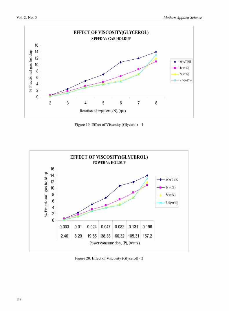
6.3 Effect of Clearance Clearance is defined as the distance between the impeller and the bottom tip of the tank vessel. If the initial height and the final height are noted as H1 and H2 the percentage of the clearance is computed by, (H2-H1/H2) * 100. The readings are measured and tabulated in Table.3. From the Figures 11 and 12, it can be concluded that a clearance of t/3 is ideal. 6.4 Effect of Liquid Height The liquid height is varied at three different positions corresponding to H=T, H>t and H<T. the readings are taken and are tabulated in Table.4. The ideal liquid height which can give maximum gas holdup and consume minimum power is found to be H<T from the Figures 13 and 14. 6.5 Effect of Electrolyte Addition The electrolytes are classified as polar, non-polar and water. The gas holdup and power consumed are computed for various densities of polar and non-polar electrolytes and tabulated in Table.5. From the Figures 15 and 16, it can be observed that NaCl is the best among polar and water is better than non-polar in providing gas holdup. 6.6 Effect of Viscosity 6.6.1 Carboxy methyl cellulose Carboxy methyl cellulose of three different densities are used and the gas holdup and power are measured and tabulated in Table.6. From the Figures 17 and 18, it is found that Carboxy methyl cellulose of viscosity 0.5% weight is the best. 6.6.2 Glycerol Glycerol of three different densities of weight is used in the vessel and the gas holdup and power readings are measured and tabulated in Table.7. It can be inferred form the Figures 19 and 20, that glycerol with 7.5% weight gives the maximum gas holdup at a low power. 6.6.3 Dilatants Dilatants of three different viscosities and density of weight are used and the values are measured and tabulated in Table.8. From the Figures 21 and 22, it can be seen that the dilatants with 0.5% weight is the best. 6.7 Effect of Vessel Diameter The vessel diameter is varied at 0.75m, 0.57m and 0.3m and the values are measured and tabulated in Table.9. The volume is computed and p/v and p/m values are tabulated in Table.10. From the Figures 23, 24, 25 and 26, it can be inferred that the ideal vessel diameter is 0.57m. 7. Conclusion Impellers are very useful in creating mass transfer between phases by creating centrifugal force in the fluid flow and also very essential in various industrial reactors for mixing. It is mandatory to have an impeller which consumes less power and produces more gas holdup. Thus this work shows the study and design of various impellers to find out the best impeller type and also the one of the dimension that is best suited for specific applications. 8. Future Development
For tall vessels the holdup generated from impeller does not travel to the bottom of the vessel, so it is suggested to use multistage contactors.
New impeller can be designed, fabricated and studied for their performances against gas holdup. CFD can be developed for various impellers to know the flow pattern. Wide range of properties of various fluids can be studied.
References Chapman, C., M., Nienow, A., W., Cooke, M., Middleton, J., C., (1981). Particle-Gas-Liquid Mixing In Stirred Vessels, Part II: Gas-Liquid Mixing, Chemical Engineering Research and Design. James R. Couper, Roy Penney, W., James R. Fair, and STAN WALAS, Chemical Equipment Design, Second Edition, Butterworth’s Publishment. Nicholas P. Chopey, Handbook of Chemical Engineering Calculation, Third Edition, McGraw hill. Rewatkar, V., B. (1989), Design of Multiphase Reactor, PhD Thesis submitted to university of Bombay. Uhl, V., W., Gray, J., B., (1986). Mixing: theory and practice, Volume III, Academic Press, Orlando, FL. Yatish T. Shah, (1979). Gas-Liquid-Solid Reactor Design, McGraw hill.
Modern Applied Science September, 2008
103
Table 1. Comparison of Impellers
Table 2. Effect of Impeller Diameter
Power (P) (watts)
% Fractional gas holdup
Speed (N) (rps)
T/2 T/3 T/4 T/2 T/3 T/4
2
3
4
5
6
7
8
17.07
57.6
136.58
266.76
460.96
731.99
1092.6
2.6
8.29
19.65
38.38
66.32
105.31
157.20
0.53
1.8
4.27
8.34
14.41
22.87
34.15
0.6
2.6
5.7
7.6
11.4
12.2
14
0.5
2.5
5
7.6
10.8
12.6
14
0.3
1.8
4.2
6.4
8
10.2
12
% Fractional gas holdup Speed (N) (rps)
Power (P) (watts) Pitched Turbine Paddle
2
3
4
5
6
7
8
2.6
8.29
19.65
38.38
66.32
105.31
157.20
0.5
2.5
5
7.6
10.8
12.6
14
0.25
1.5
3.6
5.6
7.2
8.8
10
0.1
1
2.6
4.2
6.4
7.1
8
Vol. 2, No. 5 Modern Applied Science
104
Table 3. Effect of Clearance
% Fractional gas holdup Speed (N) (rps)
Power (P) (watts) C=T/2 C=T/3 C=T/4 C=T/6
2
3
4
5
6
7
8
2.6
8.29
19.65
38.38
66.32
105.31
157.20
0.5
2.7
5.1
7.4
11
12.2
13.8
0.5
2.5
5
7
10.8
12
14
0.4
2
4.6
6.8
9.6
11.4
14.5
0.3
1.8
3.6
5.1
6.8
10.2
13
Table 4. Effect of Liquid Height
% Fractional gas holdup Speed (N)(rps)
Power (P) (watts) H1 = H<T H2 = H=T H3 = H>T
2
3
4
5
6
7
8
2.6
8.29
19.65
38.38
66.32
105.31
157.20
0.7
2.9
5.6
7.8
11.4
12.6
15
0.5
2.5
5
7
10.8
12
14
0.4
1.8
3.6
5.9
9.4
10.6
12
Modern Applied Science September, 2008
105
Table 5. Effect of Electrolyte Addition
Table 6. Effect of Viscosity – Carboxy Methyl Cellulose
Power (P) (watts)
% Fractional gas holdup Speed (N)
(rps) Den=1.1 Den=1.25 Den=1.3
0.5 (wt %)
1 (wt %)
2.5 (wt %)
2
3
4
5
6
7
8
0.0027
0.00911
0.0216
0.042
0.072
0.115
0.172
0.003
0.01
0.124
0.047
0.082
0.131
0.196
0.0031
0.01
0.125
0.049
0.086
0.136
0.20
0.3
1.6
3.4
5.2
6.9
8.1
10
0.2
1.
2.6
4.6
5.4
6.8
7.5
0.1
0.4
1.4
2.3
3.6
4.9
6
Power (P) (watts) % fractional gas holdup
Nacl Non polar
Polar
Speed (N)
(rps)
Water
Non polar Amyl
alcohol
MgSO4 Den=1.01
Den=1.07 Den=1 Den=1.1
water Amyl alcohol
MgSO4 Nacl
2
3
4
5
6
7
8
2.6
8.29
19.65
38.38
66.32
105.31
157.20
0.002
0.009
0.022
0.044
0.076
0.12
0.18
0.00248
0.00837
0.019
0.038
0.066
0.106
0.158
0.0026
0.00887
0.02
0.04
0.07
0.11
0.168
0.00245
0.00828
0.01
0.03
0.066
0.105
0.157
0.0027
0.00911
0.021
0.042
0.072
0.115
0.172
0.5
2.5
5
7
10.8
12
14
0.4
2.2
4.6
6.6
9.6
11.2
12
0.55
3
5.4
7.4
11.6
14
16
0.6
3.2
6.6
8.2
12.1
15.6
18
Vol. 2, No. 5 Modern Applied Science
106
Table 7. Effect of Viscosity – Glycerol
% Fractional gas holdup Speed (N) (rps)
Power (P) (watts) 1 (wt %) 5 (wt %) 7.5 (wt %)
2
3
4
5
6
7
8
0.0037
0.01
0.24
0.047
0.082
0.131
0.196
0.5
1.8
3.4
4.7
6.5
8.6
11
0.3
1.4
3
4.1
5.1
7.2
11
0.2
1.2
2.9
3.9
4.8
7
13
Table 8. Effect of Viscosity – Dilatants
Power (P) (watts)
% Fractional gas holdup
Speed (N)
(rps) Den=1.2 Den=1.3 Den=1.350.5
(wt %) 2
(wt %)3
(wt %)
2
3
4
5
6
7
8
0.0029
0.0099
0.023
0.046
0.079
0.126
0.188
0.0031
0.01
0.025
0.049
0.086
0.136
0.204
0.0036
0.012
0.029
0.057
0.09
0.157
0.235
0.2
1.1
2.4
3.8
4.9
7.1
9
0.1
0.8
2.1
3.4
4.2
6.8
8
0.05
0.7
1.8
2.6
3.8
5.6
7.2
Modern Applied Science September, 2008
107
Table 9. Effect of Vessel Diameter - 1
Table 10. Effect of Vessel Diameter – 2
Power (P) (watts)
% Fractional gas holdup
Speed (N)
(rps) T1 =0.75 m T2 = 0.57 m T3 = 0.3 m T1 =0.75 m T2 = 0.57 m T3 = 0.3 m
2
3
4
5
6
7
8
9.68
32.69
77.5
151.3
261.5
415.3
620
2.46
8.29
19.65
38.38
66.32
105.37
157.20
0.09
0.33
0.79
1.55
2.67
4.2
6.35
0.4
2.4
4.8
7.2
10.2
12
13
0.5
2.5
5
7.6
10.8
12.6
14
0.51
2.7
5.2
7.8
11.4
12.8
14.6
P/V (watts/m3) P/m (watts/kg) % fractional gas holdup Speed
(N)
(rps)
P1/V P2/V P3/V P1/m P2/m P3/m T1=0.75 m
T2=0.57 m
T3=0.3 m
2
3
4
5
6
7
8
66.7
225.4
534.4
1043.4
1803.4
2864.1
4276
16.9
57
135.5
246.6
457.3
726.6
1084
0.62
2.27
5.5
10.68
18.4
29.3
43.8
0.06
0.22
0.53
1.04
1.8
2.86
4.27
0.01
0.05
0.135
0.26
0.45
0.72
1.08
0.0006
0.0022
0.0054
0.01
0.018
0.029
0.043
0.4
2.4
4.8
7.2
10.2
12
13
0.5
2.5
5
7.6
10.8
12.6
14
0.51
2.7
5.2
7.8
11.4
12.8
14.6
Vol. 2, No. 5 Modern Applied Science
108
Figure 1. Experimental Setup Design
Modern Applied Science September, 2008
109
Figure 2. Pitched Impeller – 1
Figure 3. Pitched Impeller - 2
Vol. 2, No. 5 Modern Applied Science
110
Figure 4. Paddle Impeller – 1
Figure 5. Paddle Impeller - 2
Modern Applied Science September, 2008
111
Figure 6. Turbine Impeller – 1
Figure 7. Turbine Impeller – 2
Vol. 2, No. 5 Modern Applied Science
112
COMPARISON OF IMPELLERSSPEED Vs GAS HOLDUP
0
2
4
6
8
10
12
14
16
2 3 4 5 6 7 8
Rotation of Impellers (N),(rps)
% F
racti
onal
gas h
oldu
p
PITCHED
TURBINE
PADDLE
Figure 7. Comparison of Impellers – 1
COMPARISON OF IMPELLERSPOWER Vs GAS HOLD UP
0
5
10
15
2.46 8.29 19.65 38.38 66.32 105.31 157.2
Power consumption, (P), (watts)
% F
ract
iona
l gas
hol
dup
PITCHED
TURBINE
PADDLE
Figure 8. Comparison of Impellers - 2
Modern Applied Science September, 2008
113
EFFECT OF IMPELLER DIAMETER SPEED Vs GAS HOLDUP
0
2
4
6
8
10
12
14
16
2 3 4 5 6 7 8
% F
ract
iona
l gas
hol
dup
T /2
T /3
T/4
Rotation of impellers(N),(rps)
Figure 9. Effect of Impeller Diameter – 1
EFFECT OF IMPELLER DIAMETER POWER Vs GAS HOLDUP
02468
10121416
0.53 1.8 4.27 8.34 14.41 22.87 34.15
2.46 8.29 19.65 38.38 66.32 105.31 157.2
17.07 57.6 136.58 266.76 460.96 731.99 1092.65
Power consumption, (P), (watts)
% F
ract
iona
l gas
hol
dup
T /2
T /3
T /4
Figure 10. Effect of Impeller Diameter - 2
Vol. 2, No. 5 Modern Applied Science
114
EFFECT OF CLEARANCE SPEED Vs GAS HOLDUP
0
5
10
15
20
2 3 4 5 6 7 8
Rotation of impellers(N),(rps)
% F
ract
iona
l gas
hol
dup
C=T/2
C=T/3
C=T/4
C=T/6
Figure 11. Effect of Clearance - 1
EFFECT OF CLEARANCE POWER Vs GAS HOLDUP
02468
10121416
2.46 8.29 19.65 38.38 66.32 105.31 157.2
Power consumption, (P) , (watts)
% F
ract
ion
al g
as h
old
up
C=T/2
C=T/3
C=T/4
C=T/6
Figure 12. Effect of Clearance - 2
Modern Applied Science September, 2008
115
EFFECT OF LIQUID HEIGHT SPEED Vs GAS HOLDUP
02468
10121416
2 3 4 5 6 7 8
Rotation of impellers(N), (rps)
%F
ract
iona
l gas
hol
dup
H<T
H=T
H>T
Figure 13. Effect of Liquid Height - 1
EFFECT OF LIQUID HEIGHTPOWER Vs HOLDUP
02468
10121416
2.46 8.29 19.65 38.38 66.32 105.31 157.2
Power consumption, (P),(watts)
% F
ract
iona
l gas
hol
dup
H<TH=T
H>T
Figure 14. Effect of Liquid Height - 2
Vol. 2, No. 5 Modern Applied Science
116
EFFECT OF ELECTROLYTE ADDITIONSPEED Vs GAS HOLDUP
0
5
10
15
20
2 3 4 5 6 7 8Rotation of impellers, (N), (rps)
% F
ract
iona
l Gas
hol
dup
WATER
NaCl
MgSO4
amyl alcohol
Figure 15. Effect of Electrolyte Addition – 1
EFFECT OF ELECTROLYTE ADDITIONPOWER Vs HOLDUP
02
46
81012
1416
1820
0.002 0.0087 0.019 0.038 0.066 0.106 0.158
0.002 0.009 0.021 0.042 0.072 0.115 0.172
0.002 0.0082 0.01 0.03 0.066 0.105 0.157
0.002 0.0087 0.02 0.04 0.07 0.11 0.168
2.46 8.29 19.56 38.38 66.32 105.37 157.2
Power consumption, (P), (watts)
% F
ract
iona
l gas
hol
dup
WATER
POLARNaClPOLARMgSO4
Figure 16. Effect of Electrolyte Addition – 2
Modern Applied Science September, 2008
117
EFFECT OF VISCOSITY (CMC) POWER Vs HOLDUP
0
2
4
6
8
10
12
14
16
0.003 0.01 0.025 0.049 0.086 0.136 0.2
0.003 0.01 0.024 0.047 0.082 0.131 0.196
0.0027 0.0091 0.0216 0.042 0.072 0.115 0.172
2.46 8.29 19.65 38.38 66.32 105.31 157.2
Power consumption, (P) ,(watts)
% F
ract
iona
l gas
hol
dup
WATER
0.5(w t%)1(w t%)
2.5(w t%)
Figure 17. Effect of Viscosity (Carboxy Methyl Cellulose) – 1
EFFECT OF VISCOSITY(CMC)SPEED Vs GAS HOLDUP
0
5
10
15
2 3 4 5 6 7 8
Rotation of impellers, (N),(rps)
% F
ract
ion
al g
as h
old
up WATER
0.5(wt%)
1(wt%)2.5(wt%)
Figure 18. Effect of Viscosity (Carboxy Methyl Cellulose) - 2