www.f-boat.com STUDY BOOK More detailed information on Farrier multihull designs for the home builder FARRIER MARINE, INC. STUDY BOOK Page 1 Farrier Marine, Inc., P.O. Box 40675, Bellevue, Wa 98015, USA PH. (425) 462-5349, Fax 462-5364 Email: [email protected]
Transcript
www.f-boat.com
STUDY BOOKMore detailed information on Farrier multihull
F-82A L.O.A..............................................26' 11" (8.2m)L.W.L.............................................24' 6" (7.46m)Beam.............................................19' 6"(5.95m)Folded Beam..................................8' 2 1/2" (2.5m)Draft Hull only ............................1'(0.3m)Draft D/board down .....................4' 7" (1.4m)Sail Area (Main and Jib) ............408sq.ft. (37.8sq.m) Mast length...................................34'(10.36m)Mast height above water...............38' 7"(11.78m)Approx. Weight ............................1700lb(770kg) Load Capacity ...............................1400lb (636kg)Height on trailer ..........................9' 10" (3.0m)Approx. Towing Weight.................2500lb(1140kg) Auxiliary Power...........................4-8HP OutboardApprox. wind capsize force (main & jib): 33 knots
F-82R L.O.A.............................................26' 11" (8.2m)L.W.L............................................24' 6" (7.46m)Beam............................................19' 6"(5.95m)Folded Beam..................................8' 2 1/2" (2.5m)Draft Hull only ...........................1'(0.3m)Draft D/board down ....................4' 7" (1.4m)Sail Area (Main and Jib) ............430sq.ft. (39.8sq.m)Mast length..................................36'(11m)Mast height above water..............40' 7"(12.38m)Approx. Weight ..........................1500lb(680kg)Load Capacity .............................1600lb (727kg)Height on trailer ........................9' 10" (3.0m)Approx. Towing Weight...............2400lb (1100kg)Auxiliary Power.........................4-8HP OutboardApprox. wind capsize force (main & jib): 31 knots
Study Book Page 3
®
The F-82 is available in two versions, theF-82A cruiser and the F-82R racer.
The F-82R is the home builders version of theF-25C, but with a number of improvements.
The cockpit will seat six, and is large enoughfor outdoor sleeping on summer nights.Different interior layouts are possible, with anoptional enclosed head, while galley can be ateither fwd. or aft end of cabin to suit sleepingrequirements. An aft cabin option is also nowavailable.
Both cabin settees are wide and can form twovery comfortable permanent quarter berths.Forward is a large double berth, with a hugestorage area underneath. There is standing headroom under the largeand unique combination pop-top. This canslide forward for quick cabin access, have theaft end only lifted to act as a dodger, or liftcompletely up to considerably increasecomfort and room below. Sides can be fullyenclosed/screened.
Mast is an aluminum or carbon fiber rotatingwing section, and mainsail can be boomed orboomless. A retractable 'free standing' bowpole (no side stays required) is used for theasymmetric spinnaker, for convenience andeasy handling.
Daggerboard or centerboard are optional, asare a kick-up spade rudder or a transommounted rudder. An outboard of 4 to 8 HP isrecommended and this is mounted on thestern.
The interior layout shown is ageneral guideline only, andcan be varied by individualowners to suit personal taste.Items that cannot be changedare designated structuralbulkheads, and horizontalpanels taking folding strutloads
Revised: October 18, 1995Kick Up Rudder
Width of berthsis given atshoulder level.
Double bunk, 4' 6" x 6' 6"(1.37 x 2m)
Storage
Storage
Cockpit, 6' 6" (1.99m) long
Single quarter berth& settee, 23" x 8' 10"(0.59 x 2.7m)
Scale 1 : 30
0 1000 2000
0 3' 6'
Single quarter berthand settee, 24" x 6' 6"(0.61 x 2m)
Rudder pulldown line
Tube for optionalretracting spinnaker pole
Cabin mid-section,Looking forward
Cabin mid-section,Looking aft
Largeswim steparea
Cockpit bulkheadcan close off aftend of cockpit orbottom can be leftopen.
Footwells forquarter berths
Area under cockpit canbe used for storage of aportable head, or for anextra bunk.
HEADIt is difficult to find sufficient room for a true separatehead area in all boats this size, and many elaboratebuilt in head systems have been found to beimpractical. A fixed head can be located aft of theforward bunk, however, this can be difficult to usewhile overnighting as the only real solution for privacyis to clear the cabin. Experienced cruisers have found the best practicalsolution to be a Porta Potti, either aft of the forwardbunk, or slid aft under the cockpit. It can then bemoved outside to the aft swim step after dark. Atemporary canopy from aft mast support can giveprivacy if necessary.
Galley - position is optional and can be anywhere in cabinarea. If fitted at aft end, one full length bunk may be lost,unless galley swings up to give more room as shown onSheet 28. Galley has been found to work very well in forwardposition, allowing more crew cabin access when in use, and itcan be vented through small hatch in deck above
Centerboardcase
Mast support post
Floor can be fitted inmain cabin if wished
Kick-back centerboard is operated bypull up and pull down lines which areled back to cockpit
Optional Bunk Floor
Optional seat orhead area (seeabove right).
Pop-top for 1.9m (6' 3")standing headroom when up,1.64m (5' 6" when down).
Optional cover (with windows orflyscreens) to fully enclose andweatherproof pop-top when up
Daggerboard is operated by pullup and pull down lines which areled back to cockpit
The interior layout shown is ageneral guideline only, andcan be varied by individualowners to suit personal taste.Items that cannot be changedare designated structuralbulkheads, and horizontalpanels taking folding strutloads
Scale 1 : 30
Revised: September 27, 1995Kick Up Rudder
Width of berthsis given atshoulder level.
Double bunk, 4' 6" x 6' 6"(1.37 x 2m)
Storage
Storage
Cockpit, 6' 6" (1.99m)long
Single quarter berth & settee,23" x 8' 10" (0.59 x 2.7m)
0 1000 2000
0 3' 6'
Single quarter berthand settee, 23" x 6' 6"(0.59 x 2m)
Rudder pulldown line
Tube for optionalretracting spinnaker pole
Cabin mid-section,Looking forward
Cabin mid-sectionLooking aft
Large swimstep area
Cockpit bulkheadcan close off aftend of cockpit orcan be left open.
HEADThe daggerboard version offers a goodsolution for the Head, where it can be in aprivate area next to the daggerboard case.Front end of settee can be made to swingup to form an aft or fwd. wall, while acurtain slides out from alongsidedaggerboard case to give full privacy.Works very well.
Curtain
Option: Setteepanel can swingup to form aft orfwd. wall forprivate head area.
Footwells forquarter berths
DaggerboardCase
Area under cockpit canbe used for storage of aportable head, or for anextra bunk.
Galley Area - can extendto daggerboard case, orbe located aft
Optional bulkhead (full orhalf height) betweenhead and bunk
The interior layout shown is ageneral guideline only, andcan be varied by individualowners to suit personal taste.Items that cannot be changedare designated structuralbulkheads, and horizontalpanels taking folding strutloads
Revised: August 1, 2001
Width of berthsis given atshoulder level.
Double bunk, 4' 6" x 6' 6"(1.37 x 2m)
Storage
Storage
Cockpit, 4' 3" (1.3m) long
Single quarter berth& settee, 23" x 8' 10"(0.59 x 2.7m)
HEADIt is difficult to find sufficient room for a true separatehead area in all boats this size, and many elaboratebuilt in head systems have been found to beimpractical. A fixed head can be located aft of theforward bunk, however, this can be difficult to usewhile overnighting as the only real solution for privacyis to clear the cabin. Experienced cruisers have found the best practicalsolution to be a Porta Potti, either aft of the forwardbunk, or slid aft under the cockpit. It can then bemoved outside to the aft swim step after dark. Atemporary canopy from aft mast support can giveprivacy if necessary.
Galley - position is optional and can be anywhere in cabinarea. If fitted at aft end, one full length bunk may be lost,unless galley swings up to give more room as shown onSheet 28. Galley has been found to work very well in forwardposition, allowing more crew cabin access when in use, and itcan be vented through small hatch in deck above
Centerboardcase
Mast support post
Floor can be fitted inmain cabin if wished
Kick-back centerboard is operated bypull up and pull down lines which areled back to cockpit
Optional seat orhead area (seeabove right).
Pop-top for 1.9m (6' 3")standing headroom when up,1.64m (5' 6" when down).
Optional cover (with windows orflyscreens) to fully enclose andweatherproof pop-top when up
Kick Up Rudder
Traveller
Aft bunk 3' 2" x 6' 6"(.95m x 2m)
Outboard mounted onlift up bracket. Cutoutin transom/hull side toclear leg as required
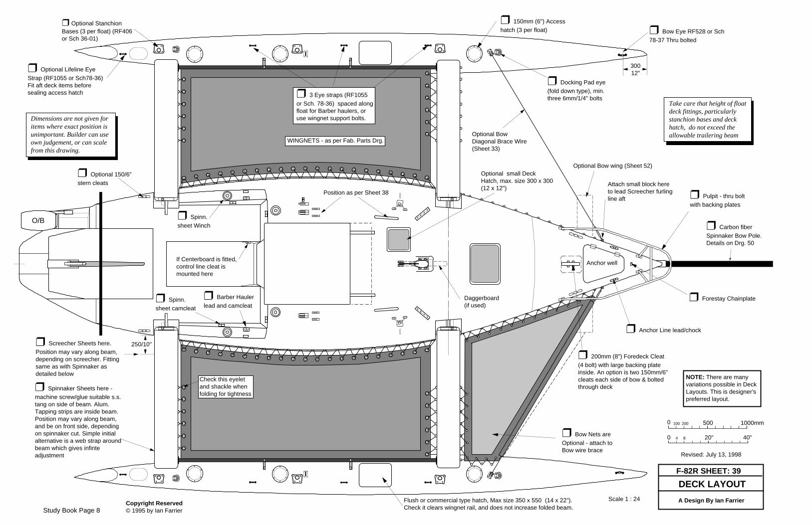
Take care that height of floatdeck fittings, particularlystanchion bases and deckhatch, do not exceed theallowable trailering beam
❒ Pulpit - thru boltwith backing plates
❒ Anchor Line lead/chock
❒ Barber Haulerlead and camcleat
Dimensions are not given foritems where exact position isunimportant. Builder can useown judgement, or can scalefrom this drawing.
Hatch
❒ Carbon fiberSpinnaker Bow Pole.Details on Drg. 50
❒ Forestay Chainplate
❒ Spinnaker Sheets here -machine screw/glue suitable s.s.tang on side of beam. Alum.Tapping strips are inside beam.Position may vary along beam,and be on front side, dependingon spinnaker cut. Simple initialalternative is a web strap aroundbeam which gives infinteadjustment
Optional BowDiagonal Brace Wire(Sheet 33)
Anchor well
❒ Spinn.sheet Winch
❒ Spinn.sheet camcleat
If Centerboard is fitted,control line cleat ismounted here
Daggerboard(if used)
Check this eyeletand shackle whenfolding for tightness
❒ Screecher Sheets here.Position may vary along beam,depending on screecher. Fittingsame as with Spinnaker asdetailed below
Attach small block hereto lead Screecher furlingline aft
❒ Optional 150/6"stern cleats
Optional small DeckHatch, max. size 300 x 300(12 x 12")
Position as per Sheet 38
Optional Bow wing (Sheet 52)
WINGNETS - as per Fab. Parts Drg.
❒ 3 Eye straps (RF1055or Sch. 78-36) spaced alongfloat for Barber haulers, oruse wingnet support bolts.
O/B
❒ Docking Pad eye(fold down type), min.three 6mm/1/4" bolts
F-9R (must be built with foam core)L.O.A...........................................30' 10" (9.4m) L.W.L..........................................30'(9.15m) Beam ..........................................22' 5"(6.84m)Folded beam .............................. 8' 2 1/2"(2.5m)Draft Hull only ......................... 1' 4"(0.41m) Draft d/board down......................5' 6"(1.67m)Sail Area (Main and Jib) ...........647sq.ft. (60sq.m.)Mast length.................................42' 6"(12.95m)Mast height above water.............47' 4"(13.65m)Approx. Bare Weight ..................2750lb(1250kg) Load Capacity ..............................2700lb (1227kg)Height on trailer ........................11' 6" (3.5m)Approx. Towing Weight...............4250lb(1932kg) Approx. wind capsize force (main & jib)32 knots
Including F-9A, F-9AX, F-9R and F-9XR
9R
®
FARRIER F-9 SERIES
The F-9 Series are true long term performance cruisers withgreat versatility from the easy trailerability.
The F-9A is the home builder's equivalent to the F-31, whichwas originally based on the F-9A. It can also use the tallerF-9R rotating mast if wished, particularly in light wind areas.
The F-9AX is a wider and roomier version of the F-9A/F-31,with a 15% wider center hull, along with the same or superiorperformance. This increases trailering width to 9' 6" (2.9m)but this can be easily trailered in most states, and manycountries without major difficulty. Usually requires just awritten permit.
The F-9R is a high performance version of the F-9A withminimal interior and a taller rotating mast. It is the homebuilders equivalent to the F-31R. The F-9R must be built infoam core and the transom hung rudder is recommended forits lighter weight and adjustability. Another variation possibleis the F-9RX with the wider F-9AX center hull, and this mustalso be built in foam.
Aft cabin versions have ample room for 4 or 5 adults, withstanding headroom in the galley area. Galley is large andcan be customized to individual taste. Cabin settees are 6' 3"(1.9m) long and these are also used for berths, with storageareas underneath. A cabin table will easily seat four, and canfold down or be put away when not in use.
Aft cabins have a double berth with full sitting headroom.Access is through a hatch in the aft cabin front, or throughunder the cockpit.
Forward cabins have a separate toilet area on the port sidewhich can be curtained off, a vanity unit is to starboard, anda cozy (snug) double berth, or large single is in the bow.Alternatively the complete bow area can be a dedicatedbathroom/head area.
Aft cockpit versions have a longer main cabin, for moreinterior space, while the larger cockpit extends to thetransom. Major advantage is a separate 'walk in' head andshower area besides the daggerboard case, and a very largedouble berth in the bow.
A higher cabin roof is optional for more standing headroom.
A daggerboard is used for simplicity, its case helping tosupport the mast. Kick-up rudder can be either transom hungor underslung in its own retractable rudder box.
An outboard of 8 to 15 HP is recommended on the stern withremote controls being located in the cockpit if needed.
Storage area insidestern seat/step isaccessible frominside aft cabin
Storage areas eachside of aft bunk
0 1000 2000
0 3' 6'
Watertight CollisionCompartment
Self-draining Anchor Well
Storage or watertightCompartment
Forward Berth, 1.9m x 1m (6' 3" x 3' 3").Width can be increased by raising, butat cost of sitting headroom
Second Anchor Well for largeranchor can be located here, oruse cockpit locker
Marine Head, holding tankcan be fitted under headfloor or under fwd. Berth
Aft Bunk , 2m x 1.05m (6'6" x 3' 5"). Can be madelonger if wished.
Light inboard motor can be fittedhere if wished (Sht. 79) or area canbe used for an Icebox, either built inor portable
Self-drainingCockpit
Storagecompartments
Fwd. Bulkhead separates Headfrom Fwd. Bunk. Can be omittedfor more open bow area. A coveror seat over head could thenswing up when head is in use. Anadditional deck stiffener (Sheet17) will be required here ifbulkhead is omitted.
Daggerboard is operated by pullup and pull down lines which areled back to cockpit
Storage
Storage
Head Area can also be usedas a sit down shower
Optional WashBasin/Vanity unit
Storage
Hanging Lockercan be fitted here
Galley Area -Stove can belocated on Stbd side if wished. Galley Storage
20 gal Watertank underFwd. end of settee berth
Optional Chart table (flap folds out), orStove location, or, can be built in asHanging Locker. Icebox could also be builtin here if preferred.
Note: With modern Electronics, GPS,Sat-Nav etc. the need for a dedicatedChart table is greatly reduced. CabinTable can be used for those times achart table is necessary.
WatertightCompartment
Floor level to here gives 1.69m(5' 7") headroom in fwd. part ofcabin. This floor can be omittedif wished for more headroom.
Battery storage
The interior layout shown is ageneral guideline only, andcan be varied by individualowners to suit personal taste.Items that cannot be changedare designated structuralbulkheads.
1.9m x .53m (6' 3" x 21")settee berth Scale 1 : 36
PrivacyCurtain
Revised: January 14, 1999
Kick Up RudderTransom Ruddernow also optional
PassagewayForward
F-9AX Layout is on Sheet 54Aft Cockpit Layout is on Sheet 60
Width of berthsis given atshoulder level
F-9A Sheet 27
A Design By Ian Farrier
The separate aft cockpit versionhead compartment may also beused in aft cabin version. Maincabin area is reduced, butforward berth is larger
Optional highercabin
Cabin roof may beraised by up to64mm/2 1/2" ifwished
Std. headroom atCabin hatch area is1.88m (6' 2")
Study Book Page 10
Cabin roof maybe raised by upto 64mm/2 1/2" ifwished
Storage area insidestern seat/step isaccessible frominside aft cabin
Storage areas eachside of aft bunk
0 1000 2000
0 3' 6'
Watertight CollisionCompartment
Self-draining Anchor Well
Storage or watertightCompartment
Forward Berth, 1.9m x 1.14m (6' 3" x 3' 9").Width can be increased by raising, but atcost of sitting headroom
Second Anchor Well for largeranchor can be located here, oruse cockpit locker
Marine Head, holding tankcan be fitted under headfloor or under fwd. Berth
Aft Bunk , 2m x 1.2m(6' 6" x 4'). Can bemade longer if wished.
Light inboard motor can be fittedhere if wished or area can be usedfor an Icebox, either built in orportable
Self-drainingCockpit
Storagecompartments
Fwd. Bulkhead separates Headfrom Fwd. Bunk. Can be omittedfor more open bow area. A coveror seat over head could thenswing up when head is in use. Anadditional deck stiffener (Sheet17) will be required here ifbulkhead is omitted.
Daggerboard is operated by pullup and pull down lines which areled back to cockpit
Storage
StorageHead Area can alsobe used as a sitdown shower
Optional WashBasin/Vanity unit
Storage
Hanging Lockercan be fitted here
Galley Area -Stove can belocated on Stbd side if wished.
Galley Storage 20 gal Watertank under Fwd. end of1.9m x 0.73m (6' 3" x 29") settee berth
Optional Chart table (flap folds out), orStove location, or, can be built in asHanging Locker. Icebox could also be builtin here if preferred.
Note: With modern Electronics such asGPS, the need for a dedicated Charttable is greatly reduced. Cabin Tablecan be used for those times a charttable is necessary.
WatertightCompartment
Floor level to here gives1.69m (5' 7") headroom infwd. part of cabin. This floorcan be omitted for moreheadroom.
Battery storage
The interior layout shown is ageneral guideline only, andcan be varied by individualowners to suit personal taste.Items that cannot be changedare designated structuralbulkheads.
Forward Double Berth, 1.9m x 1.2m(6' 3" x 4'), can be made longer ifwished. Can also extend further aft tobeam bulkhead for more width inF-9A version.
Optional Aft Bunk 2m x 0.9m (6' 6" x 3').
Light inboard motor can befitted here if wished or areacan be used for an Icebox,or extra bunk as shown
Self-draining Cockpit (seats 6).Will require bridge across atbeam area
Storagecompartments
Daggerboard is operated bypull up and pull down lineswhich are led back to cockpit
Wash Basin &Vanity unit
Optional counter top or,can be built in as HangingLocker. Icebox could alsobe built in here if preferred.
The interior layout shown is ageneral guideline only, andcan be varied by individualowners to suit personal taste.Items that cannot be changedare designated structuralbulkheads.
0 1000 2000
0 3' 6'
Scale 1 : 36
Revised: January 22, 1999
Kick UpRudder
Passageway toForward bunk
Width of berths isgiven at shoulderlevel. Berths canbe made longer ifwished
Storage
Storage
Storage
F-9AX is shown.All widths will bereduced by 15%with F-9A.
Dotted lineshows F-9Asize
Storage
Walk-in Head and showerarea (1.75m/5' 9" headroom).
Bi-fold door
Seat
Storage
Storage
Aft end of cockpit canbe left completely openif wished
Drop in panel toincrease galley toparea
Settee berth -1.8m x 0.57m(5' 11" x 23")
Settee berth - 1.99m x0.57m (6' 6" x 23")
Table flap folds down
F-9A Sheet 60
Galley Area -Stove can belocated on Stbd side if wished.Galley area can be increased byextending under cockpit.
Optional Floor
Bunk can be extended to BeamBulkhead in F-9A
Storage
Note: Head and fwd. bunk layout asshown can also be used in Aft Cabinversion, but at expense of main cabinroom (port settee would be too smallfor use as bunk). Extended galley canalso be used in Aft Cabin version.
Cabin roof may be raised byup to 64mm/2 1/2" if wished
❒ Strong Pad eye (RF2365 or Sch.78.07) for Shroud tensioner (not requiredwith F-9R). Through bolt close to aftbulkhead and beam with backing plate.Extra glass inside as per Sheet 6.
❒ Bow Eye RF528or Sch 78-37
❒ Optional StanchionBases (3 per float)(RF406 or Sch 36-01)
RF : Ronstan PartSch : Schaeffer PartHK : Harken Part
Revised: January 21, 1999
❒ Pulpit - thru boltwith backing plates
❒ Anchor Linelead/chock
Anchor well
❒ Bow Toerail - as per drg.
❒ Deck OrganizersPack up as requiredto align with lines.
❒ Halyard Winch
❒ Sheet Winch ❒ D/Bd Clamcleat
❒ Jib Halyard❒ Spinn. Halyard
❒ Main Halyard❒ D/Bb. Clamcleat
Outboard
❒ O/b RemoteControl
❒ O/b Steering
❒ SpinnakerSheet winch
❒ 200mm (8")Cleat
❒ AftCabin Vent
Mainsheet traveller asper Drg. 38
❒ Barber Haulerlead and camcleat
Dimensions are not given foritems where exact position isunimportant. Builder can useown judgement, or can scalefrom this drawing.
❒ Hatch (574 x 574mm-22.5 x 22.5") or similar
❒ Foredeck Hatch440 x 580mm (17.5 x22.5") or similar
Shroud Chainplate (drg. 38)
0 500 1000mm
0 40"20"4 8
100 200
F-9A SHEET: 39
A Design By Ian Farrier
DECK LAYOUT
❒ Spinnaker BowPole (Drg. 50 or 65)
WINGNETS - as per Drg. 38
46018"
Pull downline
Pull up
line
❒ Clamcleat❒ Bow Chainplate& Roller assembly. asper separate drg.
❒ 3 Eye straps (RF1055or Sch. 78-36) spaced alongfloat for Barber haulers. Analternative is to use wing netrail support bolts
❒ Hatch 390 x 520mm (15 "x20.5") or similar, or make as perSheet 41. Float hatches mustnot leak
❒ Eyeplate forBow and Spinn.Bow Pole bracewires and Lifelineend (Drg. 38)
Bow Net SupportWire(Drg. 33)
❒ 250mm (10") ForedeckCleat with large backing plate
F-9AX
F-9AX
❒ Spinnaker Sheets here - screw/glue suitables.s. tang (3 x 32) on aft side of beam. Position willvary along beam, depending on spinnaker. Findbest position by using a temporary rope stroparound beam and using spinnaker
Trailer lights - Check withlocal regulations for correctlight configuration. Tail lights are best onseparate removable bracketsmounted on Transom, withcable run independently overboat. Avoid trailer mountedlights - salt water soonrenders them inoperative
Bracket for mast on pulpit. Canbe offset to clear spinnakerpole. Be sure bracket ismounted in front of forestay(shown by dotted line. Mast islashed to bracket when trailering
Bow Nav. light
Trailer winch line being usedto raise mast (connected toJib halyard)
Mast RaisingPole
Mast in raisingposition
Aft MastSupport
Rudder inrecommendedtraileringposition
Tie down lineTrailer tiedown loop
Mast in traileringposition
Brace mast support to travelleror aft deck as shown with20mm/3/4" s.s. tube (Spinn.pole strut could be used)
Bow Roller
If required, separate support bracket can bemade for bow to raise mast above towingvehicle. Mast can be moved further forwardif required to limit overhang out the rear.
Spinnaker polecan be removed orstored vertically fortrailering ordocking.
Wire/line preventspole falling forwardor use a halyard
Mast Raising pole has a tendency to stayon center, but to be safe, particularly incross winds or on a sideways slope, twolight wires can be rigged from the pole tothe raising wire Deck Anchors.
Height on Trailer : 3.5m (11' 6") (Will vary, depending on type of trailer used)
Set up trailer as perSheet 52
See also Sheet 67 for F-9R
Raisingwire
Deck Anchor
Study Book Page 16
Study Book Page 17
The F-36 is in the process of being replaced by the F-38
F-36 L.O.A...............................................36' 10" (11.2m) L.W.L...............................................35' 8"(10.88m) Beam ..............................................26' 1"(7.95m) Draft Hull only ............................. 1' 8"(0.5m) Draft d/board down........................6' 9"(2.07m)Sail Area (Main and Jib) ..............838sq. ft.(77.5sq.m.)Mast length....................................49'(14.94m)Mast height above water................54' 8"(16.65m)Approx. Weight .............................6500lb(2740kg) Load Capacity ................................3000lb (1360kg)Auxiliary Power............................20-30 HP InboardApprox. wind capsize force (main & jib): 38 knots
FARRIER F-36
36
®
The F-36 is a large, ocean going, cruising multihull, withthe capability of being demounted (not folding) foroccasional trailering at 10' (3.05m) wide. This givestremendous versatility for an ocean capable boat.
Interior can accommodate six to eight, with standingheadroom throughout. Galley is to port, and a chart tableis on the starboard side, along with a wet locker. Dinettewill seat five, and can be converted into a large doublebunk. Starboard settee is wide and comfortable, and canbe converted into top and bottom bunks.
Forward, there is a private bathroom with head,washbasin, and a separate shower. Forward cabin has adouble berth, with seating room aft, and large storageareas underneath.
The aft cabin has a double or two single berths with fullsitting headroom. Access is through a hatch in the aftcabin front, or through under the cockpit.
An optional pilothouse can shelter the cockpit, givingstanding headroom to the forward end of the aft cabin,and an all weather passage to the main cabin throughthe cockpit.
The optional aft cockpit version gives even more maincabin space, while the cockpit size is considerablyincreased, with easier access over the stern.
Daggerboard or centerboard are optional, while akick-up spade rudder is housed in its own retractablerudder box in the transom. Wheel steering is standard,but a tiller is optional with the aft cockpit version.
The self-draining center cockpit can seat six adults, aftcockpit eight to ten.
An inboard of 20 to 30HP is recommended, located in aroomy and accessible area under the cockpit.
The beams are demountable, to give an occasionaltrailering capability at 10' (3m) wide. The strut reinforcedbeams eliminate the need for full width beams,increasing interior room. The beams are smaller, lighter,easier to demount, and allow standing headroombetween the forward beams.
The interior layout shown is ageneral guideline only, andcan be varied by individualowners to suit personal taste.Items that cannot be changedare designated structuralbulkheads.
Revised: December 6, 1994
Aft Cockpit Layout is on Sheet 29
Figures shown are1.8m (5' 11") tall.Width of berths isgiven at shoulderlevel.
F-36 Sheet 28
A Design By Ian Farrier
Scale 1 : 40
0 1000 2000
0 3' 6'
Watertight CollisionCompartment
Self-drainingAnchor Well
Daggerboard is operated bypull up and pull down lineswhich are led back to cockpit
Optional table slides under cockpitwhen not in use, or can be used toconvert aft bunks into double -1.92m x 1.7m (6' 3" x 5' 7"). An optional washbasin/vanity canbe fitted under forward end.
Separate enclosed bathroom(6' to 6' 2" headroom). Showeris 800 x 830 (31 x 32")
ChartTable
Passagewayunder cockpit
Icebox
Engine
Dinette (seats 4 - 5) can be convertedto large double 1.94m x 1.4m (6' 4" x4' 7") and can be curtained off
HangingLocker
Wet Locker
Storage
StorageStorage
Storage
Storage
Optional Centerboardshown on Aft Cockpitlayout - Sheet 29
Storage
Storage
Fuel Water
Two 80L./20 gal.water tanks
Storageunderdinette
Settee back canconvert to top bunk
25 gal. fuel tank
A
A
B
B
View A-A View B-B
Passage-way aft
Storage
Double berth, 2m x 1.15m(6' 6" x 3' 9") Size can beincreased by extendingfurther aft
Settee berth1.92m x 0.63m6' 4" x 2' 1"
Storage
Storage
Optional demountablePilothouse (Sheet 55).Shelters cockpit and givesstanding headroom toforward end of aft cabin.
Either Centerboard orDaggerboard styleinteriors can be used inAft Cabin or Aft Cockpitversions.
The use of separate braceddemountable beams (similar tofolding beams) avoids a full widthbeam and consequent loss ofstanding headroom in this area
Sail StorageThe F-36 needsrelatively few sails,and these can bestored in the floats,to avoid clutteringthe interior
Cockpit coaming can beraised and shape variedto suit individualrequirements
Cockpit seats are 1.58m(5' 2") long. Can beextended up to 1.88m(74") long, if required, bymoving aft cabin fwd.side further aft
Optional washbasin
In the interests of ultimate safety,and to take full advantage of totalunsinkability, the F-36 has severaldesigned in features for safe andcomfortable survival in the unlikelyevent of capsize. These include an emergency safetygear compartment, accessible fromtop and bottom, an escape/re-entryhatch (usable if inverted), andconvertible bunks that can be usedeither way up.
The interior layout shown is ageneral guideline only, andcan be varied by individualowners to suit personal taste.Items that cannot be changedare designated structuralbulkheads.
Revised: December 6, 1994
Aft Cabin Layout is on Sheet 28
Figures shown are1.8m (5' 11") tall.Width of berths isgiven at shoulderlevel.
F-36 Sheet 29
A Design By Ian Farrier
Scale 1 : 40
0 1000 2000
0 3' 6'
Watertight CollisionCompartment
Self-drainingAnchor Well
Self-drainingCockpit
Centerboard is operated by pullup and pull down lines which areled back to cockpit from just aft ofmast.
ChartTable
Settee can be converted to largedouble 2.1m x 1.32m (6' 11" x 4' 4")and can be curtained off
HangingLocker
WetLocker
Storage
Storage
Optional Daggerboardshown on Aft Cabinlayout Sheet 28
Storage
Storage
Fuel
80L./20 gal.water tanks
Settee back canconvert to top bunk
25 gal. fuel tank
A
A
B
B
View A-A View B-B
Centerboardcase
Access Aft
Storage
Settee berth 2m x 0.63m6' 6" x 2' 1"
Storage
Storage
Either Centerboard orDaggerboard style interiorscan be used in Aft Cabin orAft Cockpit versions.
Storage
Hinged panel swingsup when settee isused as bunk
Settee back is used asdrop in panel to convertsettee to double
This area can also beconverted to wing berth
Table folds down whennot in use
Icebox
Separate enclosed bathroom(6' to 6' 2" headroom). Showeris 800 x 830 (31 x 32")
Sail StorageThe F-36 needsrelatively few sails,and these can bestored in the floats,to avoid clutteringthe interior
Cockpit coaming can beraised and shape varied tosuit individual requirements
Cockpit is 2.74m(9') long
Double berth, 2m x 1.15m(6' 6" x 3' 9") Size can beincreased by extendingfurther aft
TRAILERINGThe F-36's trailerability is intended only for occasionaltrailering, such as winter storage, or spending winter in awarmer climate. It is not intended for frequent weekend use.It could take a full day to demount and trailer, and craneassistance will be required to lower mast. However,manpower may be sufficient to move beams and floats. Thetrailer will require submerging for retrieving or launching,unless a travel hoist is used.
Trailer Regulations - Check with local authorities formaximum width, length, brake requirements etc. A writtenpermit is usually the only requirement in the U.S. for a3.05m (10') wide load such as the F-36.Select a trailer that will allow the keel support board to beset low. A 'Deep V' type powerboat trailer is usually made toallow this.
Lights - Check with local regulations for correct lightconfiguration. Tail lights are best on separate removablebrackets or bar, mounted on Transom.
Support aftend of mastif required
Rudder isremovedfor trailering
Tie down line or strap -go to coaming or overcomplete boat at aft end
Trailer tie downloop
Mast in trailering position. Willrequire spreaders and wires tobe removed. Set higher at front if necessaryto clear towing vehicle
Min. required Load Capacity: 4000kg/ 8800lb
Depends on built weight and amount of
gear carried. Tandem or Triaxle required
Trailering Width : 3.03m (9' 11")
Trailering Height : 3.8m (12' 6") (Will vary, depending on type of trailer
used.
❒ Keel support to be curvedup at aft end as shown. Packas required. Must bear evenlyon hull.
Forward support
Min. 32mm (1 1/4") ply endsupports, fitted in Beamrecesses and bolted torecess through beam boltholes
Set floats to clear winches, and leave enoughspace between for mast. Floats can belowered further by removing winches. Floatbeam bulkheads to align with cradles.
Min. 32mm (1 1/4") ply cradles,bolted to end supports using metalangle at corners. Openings can becut as shown. Pad well against float(horizontal plate recommended).
Approx.97038"
Approx. 630/25"
Hull side support
Heavy padded Keel board, 300-400(12 - 16") wide, curved to suit hull.Try to locate major supports atinternal bulkhead positions
The new F-39 range of designs will supplement the F-36, plans of which were originally released in 1994. There will be three versions of the F-39 as follows:
F-39 Sport CruiserThe perfect high performance cruiser, and available in both aft cabin and aft cockpit versions. Performance will be about equivalent to an F-31R - faster in some conditions, slower in others.
F-39R Sport RacerA very high performance version, with a more basic interior, and also available in both aft cabin and aft cockpit versions. Performance will be significantly superior to an F-31R, in all conditions.
F-39ST SUPERTRI An exciting new model and designed for those who want a premier performance trimaran without any compromises. Specifications include fully vacuum bagged epoxy/carbon construction and a rotating carbon wing mast. Interior will be basic, but still very roomy and practical. Performance will be simply outstanding in all conditions.
All models will be fully transportable by road trailer, with the demounting process further streamlined to make it more feasible to attend major events with a reasonable set up and take down time, and without any outside assistance. A narrower demountable version that can be economically shipped anywhere in the world inside two 40' containers is also being considered, as this could make foreign cruising a realistic possibility for many, without the need to spend months getting there, and with much less risk of shipping damage.
Folding capability via the Farrier Folding System for marina docking, or canal traversing, will be standard. Floats will fold in more vertical to eliminate the need for any anti-fouling on the float side. However, it should be noted that folded trailering will not be a feature, as the center hull and floats would have to be too small to achieve a legal trailering width in this size boat.
Rotating masts with synthetic rigging and carbon fiber chainplates will be standard across the range, as will a 'kickup' daggerboard style rudder. A conventional fixed mast with stainless steel rigging will still be an option for the cruiser, but rotating masts with synthetic rigging are now looking more reliable, with fewer rigging connections required, while synthetic line is not as fatigue or corrosion prone as stainless steel wire.
PLANSThe following pages detail actual plan contents and have examples oftypical trimaran plan sheets. Some reinforcing fabric specifications are
considered proprietary or confidential and have been blanked off.
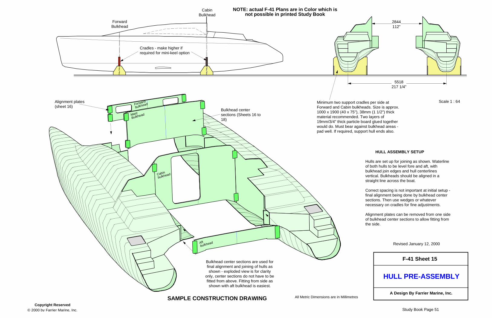
If one wants to build a superb boat, efficiently and quickly, then there is no better way than to start with comprehensive and highly detailed plans. Farrier plans are simply the best available, with extensive computer generated 3-D drawings for clarity, and step by step, detailed procedures, to help eliminate hundreds of hours of building or 'working it out' time by the builder.All plans include details on the very latest vertical foam stripping construction methods that have proved so fast, as well as more traditional 'low tech' wood strip planked construction options.All of the many options for each model such as a choice between aft cabin or aft cockpit versions in the F-82, F-9A and F-36, or a daggerboard or centerboard in the F-82R, F-36 and F-41 are included standard in all plans.A good set of plans is vital to the success of any building project, and these, along with the designer's reputation, can add thousands of dollars value to the finished product.PLAN BOOKThe construction plans are in a large format 'production style' book form, which guide construction step by step, and in the correct sequence, for maximum ease and efficiency.Large plan sheets are not used, as these usually just give specifications with no guidelines on what to do first, or how to do it, as well as being awkward to handle. Planning construction thoroughly, and then detailing when and how things should be done, can save both amateur and professional builders literally hundreds of hours.The F-41 plans are in full color, to make it even easier and clearer for the builder to follow each step, and color drawings will be added to other plans as time permits.FULL SIZE PATTERNSComprehensive full size frame patterns (all now in color) are included with all models, even for bulkheads and many other interior panels. Anyone who has had to make these from a bare hull will appreciate what a time saver this can be. Dxf files for frames and bulkheads are also available at extra cost, and these can be used for cutting frames via a computer controlled cutter.FABRICATED PARTS BOOKAll plans include a Fabricated Parts Book, which fully details and specifies all the various smaller parts, such as chainplates, mast step, and the folding system struts. Such detailed drawings can offer considerable savings by allowing the builder to make many parts, avoiding countless hours in working out how to make them.MANUALSComprehensive Building and Sailing Manuals are included with all plans, with many photos, detailed guidelines on construction techniques and methods, along with hints on trailering, rigging, launching, and practical sailing techniques developed from many years of sailing Farrier designs.EFFICIENT PROCEDURESExtensive practical experience in personally building five trimarans and then setting up Corsair Marine's production assembly line in the eighties has shown that most building time actually goes into assembly, fit out and finishing. Thus special care and attention has been directed into these areas, with the use of production procedures, to reduce construction time.For efficient building, it is vitally important that each task is done properly and in the right order, and many quick and easy to build systems/hints are incorporated.Farrier plans thus ensure the easiest and fastest to build multihulls, and very cost competitive, particularly when the usual high resale value of any Farrier design is factored in.
COMPAREIf considering any other design then be sure to insist on first seeing some actual construction drawings and the materials list. There is no reason why several sample construction drawings cannot be made available to prospective builders, as any proprietary information can be easily blanked off. Such sample drawings will then enable one to see how good the plans are, and how much you are expected to work out.Extensive and detailed plans are what make a boat simpler and easier to build, not lack of detail. Don't be fooled.BACKUPThe plan cost always includes personal backup/support by Ian Farrier, draftsmen or other inexperienced persons not being used, and all emails, phone calls etc. are always answered. Plans are constantly being revised and the new builder can be assured of receiving the latest most advanced plans, plus updates for many years as improvements come to light.SOME COMMENTS RECEIVED ON PLANS:My friend was astonished when I showed him the details of the plans. Last year I forgot to compliment you enough about the quality of your plans. As a professional designer and engineer, I fully appreciate the effort you put in detailing every phase of the construction process and the instant email support you give to every question. Bepi Bottacin, F-82R, Soanara, ItalyI have built several boats and Tom is an engineer, we both continually marvel at the accuracy and detail of Ian's plans. They are a joy to build from and contain only a couple of "irksome" (Ian's word) maneuvers and head scratchers.Mike Winkler, building F-9s with Tom Comstock, MichiganWhere the knowledge of composite engineering is concerned, Ian Farrier has resolved all that for me by providing, what are to my knowledge, the most detailed building plans available, with full-size patterns. All a Farrier builder needs is a decent dose of common sense and perseverance. If that's not enough, Ian backs up his plans with the best e-mail info and service I have ever experienced!Dennis Meulensteen , NetherlandsThank you very much for the Sailing Manual received yesterday. I am stunned by the level of detail and assistance in your plans Ian - they are remarkable.Chris Rowntree, Nova Scotia, CanadaOther plans seen have consisted of just a few plan sheets, some even having a list of notes stapled on one side - the study drawings for the F-41 alone give more information on building a boat.Chris Treadwell, Qld. Australia I'd like to take this opportunity to thank you for taking the time to develop such explicit and detailed instructions. Building F82R #91 is less like work and more like a series of finite steps that make it easy to plan the construction Douglas Foster, Newton, Kansas
PLAN COSTA good well detailed set of plans are not inexpensive, as they take considerable time and can make or break a project. Saving a little here can be a very expensive mistake, as one could then spend hundreds of extra hours working out how to build, or items or features may not actually fit or work as originally claimed. Worse, once finished, the resale value could be tens of thousands less with an unknown design.
TYPICAL PLAN CONTENTS:
General Plan Book (from 60 to 78 pages depending on model)
Beam and Folding System Plan Book(up to 20 pages for all folding models)
Full Size Patterns (for all hulls plus interior bulkheads and many interior panels)
Fabricated Parts Book (from 27 to 57 pages - detail drawings for small metal or plastic parts)
Building Manual(General guide for building methods and techniques)
Sailing Manual(General guide for sailing and sailing techniques)
Materials list(A comprehensive list of all materials required)
Optional DXF files ($50 additional fee)For computerized cutting of Form Frames
F-82 PLANS - Table Of Contents
1. General Construction Details2. Strongback Construction3. Float Frame Set-up4. Float Construction5. Float Construction - Bulkheads6. Float Construction - Joining7. Float Construction8. Main Hull Frame Set-up9. Main Hull Port Side Construction10. Main Hull Bulkheads (aft) 11. Main Hull Bulkheads (fwd.) 12. Main Hull External Glassing13. Main Hull Stbd. Side Construction 14. Dagger and Centerboard Case Construction 15. Dagger and Centerboard Case Installation16. Main Hull Joining - Exterior17. Main Hull Joining - Interior18. Main Hull Exterior Lamination19. Central Mounting Modules - Fitting20. Central Mounting Modules - Positioning 21. Fitting Forward C.M.M.22. Fitting Forward C.M.M. (Taping)23. Fitting Forward C.M.M. (Taping)24. Fwd. Passageway and Mast Support Systems25. Fitting Aft C.M.M. and Taping26. Cockpit Construction27. Interior Layout (centerboard)28. Interior Construction29. Interior Construction30. Interior Layout (daggerboard)
31. Folding System Assembly32. Beam and Float Assembly33. Beam Locks & Diagonal Braces34. Transom and Outboard Details35. Window and Wingnet details36. Dagger and Center board Construction37. Dagger and Center board Installation38. Deck Construction Details39. Deck Layout40. Pop-top Details41. Float Miscellaneous Details42. Rudder Blade Construction43. Rudder Case Construction44. Rudder Case Assembly45. Mast Assembly46. Running Rigging47. Standing Rigging48. Sail Plan49. Spinnaker Bow Pole50. Trailer Details51. Trailering52. Optional Bow Wing Details53. Optional Boom Assembly54. Optional Transom Rudder55. Optional Mast Raising Deck Loops56. Optional Aft Cabin57. Optional Aft Cabin
Plan Book for Mounting Modules, Beams & Folding System1. Index and Materials2. Central Mounting Module Components3. Central Mounting Module Construction4. Central Mounting Module Assembly Jig5. Central Mounting Module Assembly6. Central Mounting Module Completion7. Metalwork - Folding Struts8. Metalwork - Lower F. Strut Brackets9. Metalwork - LFS Pivot Pins & Bolt Pads10. Metalwork - UFS Pivot Pin & Beam Bolt11. Beam Construction12. Beam Mold13. Beam Foam and Internal Lamination14. Beam Bottom Lamination15. Beam Internal Lamination16. Beam Internal Lamination17. Beam Folding Fittings18. Beam Top Lamination19. Beam Top Lamination20. Beam & Hull Preparation for Assembly
Float Full Size Patterns (Sheets1, 2, 3 & 4)Main Hull Frame Patterns (Sheets 5, 6, 7, 8 & 9)Main Hull Interior Panel Patterns (Sheets 10, 11, 12, 13 & 14)Miscellaneous Full Size Patterns (Sheets 15, 16 & 17)Beam Patterns (Sheets A & B)Building Manual (36 pages)Fabricated Parts Book (27 pages)Materials list and sources for materials (5 pages)Sailing Manual (46 pages)
FARRIER MARINE, INCStudy Book Page 30
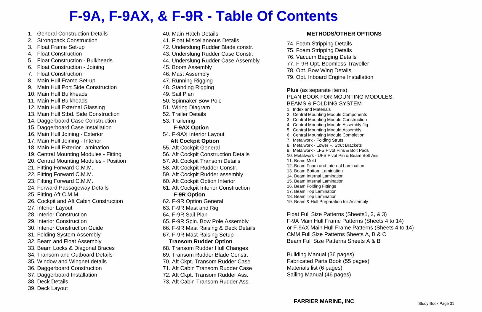
F-9A, F-9AX, & F-9R - Table Of Contents1. General Construction Details2. Strongback Construction3. Float Frame Set-up4. Float Construction5. Float Construction - Bulkheads6. Float Construction - Joining7. Float Construction8. Main Hull Frame Set-up9. Main Hull Port Side Construction10. Main Hull Bulkheads 11. Main Hull Bulkheads 12. Main Hull External Glassing13. Main Hull Stbd. Side Construction 14. Daggerboard Case Construction 15. Daggerboard Case Installation16. Main Hull Joining - Exterior17. Main Hull Joining - Interior18. Main Hull Exterior Lamination19. Central Mounting Modules - Fitting20. Central Mounting Modules - Position 21. Fitting Forward C.M.M.22. Fitting Forward C.M.M.23. Fitting Forward C.M.M.24. Forward Passageway Details25. Fitting Aft C.M.M.26. Cockpit and Aft Cabin Construction27. Interior Layout28. Interior Construction29. Interior Construction30. Interior Construction Guide31. Folding System Assembly32. Beam and Float Assembly33. Beam Locks & Diagonal Braces34. Transom and Outboard Details35. Window and Wingnet details36. Daggerboard Construction37. Daggerboard Installation38. Deck Details39. Deck Layout
Plus (as separate items):PLAN BOOK FOR MOUNTING MODULES, BEAMS & FOLDING SYSTEM1. Index and Materials2. Central Mounting Module Components3. Central Mounting Module Construction4. Central Mounting Module Assembly Jig5. Central Mounting Module Assembly6. Central Mounting Module Completion7. Metalwork - Folding Struts8. Metalwork - Lower F. Strut Brackets9. Metalwork - LFS Pivot Pins & Bolt Pads10. Metalwork - UFS Pivot Pin & Beam Bolt Ass.11. Beam Mold12. Beam Foam and Internal Lamination13. Beam Bottom Lamination14. Beam Internal Lamination15. Beam Internal Lamination16. Beam Folding Fittings17. Beam Top Lamination18. Beam Top Lamination19. Beam & Hull Preparation for Assembly
Float Full Size Patterns (Sheets1, 2, & 3)F-9A Main Hull Frame Patterns (Sheets 4 to 14)or F-9AX Main Hull Frame Patterns (Sheets 4 to 14)CMM Full Size Patterns Sheets A, B & CBeam Full Size Patterns Sheets A & B
Building Manual (36 pages) Fabricated Parts Book (55 pages)Materials list (6 pages)Sailing Manual (46 pages)
FARRIER MARINE, INC Study Book Page 31
F-36 Plan Book - Table Of Contents
1. General Construction Details2. Strongback Construction3. Float Frame Set-up4. Float Construction5. Float Construction - Bulkheads6. Float Construction - Joining7. Float Construction8. Main Hull Frame Set-up9. Main Hull Port Side Construction10. Main Hull Bulkheads 11. Main Hull Bulkheads 12. Main Hull External Glassing13. Main Hull Stbd. Side Construction 14. Daggerboard Case Construction 15. Daggerboard Case Installation16. Opt. Centerboard Case Construction17. Opt. Centerboard Case Installation18. Main Hull Joining - Exterior19. Main Hull Joining - Interior20. Main Hull Exterior Lamination21. Beam Recesses22. Fwd. Beam Bulkheads23. Aft Beam Bulkheads24. Inboard Engine Installation25. Cockpit and Aft Cabin Construction26. Aft Cockpit Construction Details27. Transom Details28. Interior layout (Aft Cabin)29. Interior layout (Aft Cockpit)30. Interior Construction31. Interior Construction
Float Full Size Patterns Sheets 1 to 6F-36 Main Hull Frame Patterns Sheets 7 to 21Building Manual (36 pages)Fabricated Parts Book (34 pages)Materials list (5 pages)Sailing Manual (46 pages)
FARRIER MARINE, INC
Study Book Page 32
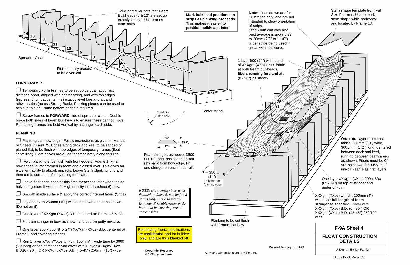
FORM FRAMES
❒ Temporary Form Frames to be set up vertical, at correct distance apart, aligned with center string, and with top edges(representing float centerline) exactly level fore and aft andathwartships (across Strong Back). Packing pieces can be used toachieve this on Frame bottom edges if required.
❒ Screw frames to FORWARD side of spreader cleats. Doublebrace both sides of beam bulkheads to ensure these cannot move.Remaining frames are held vertical by a stringer each side.
PLANKING
❒ Planking can now begin. Follow instructions as given in Manualor Sheets 74 and 75. Edges along deck and keel to be sanded orplaned flat, to be flush with top edges of temporary frames (floatcenterline). Float halves are glued together later, along this line.
❒ Fwd. planking ends flush with front edge of Frame 1. Finalbow shape is later formed in foam and glassed over. This gives anexcellent ability to absorb impacts. Leave Stern planking long andthen cut to correct profile by using template.
❒ Leave float ends open at this time for access later when tapinghalves together. If wished, fit High density inserts (sheet 6) now.
❒ Lay one extra 250mm (10") wide strip down center as shown(Do not omit).
❒ One layer of XXXgm (XXoz) B.D. centered on Frames 6 & 12 .
❒ Fit foam stringer in bow as shown and bed on putty mixture.
❒ One layer 200 x 600 (8" x 24") XXXgm (XXoz) B.D. centered atFrame 6 and covering stringer.
❒ Run 1 layer XXXm/XXoz Uni-dir. 100mm/4" wide tape by 3660(12' long) on top of stringer and cover with 1 layer XXXgm/XXozB.D.(0 - 90°), OR XXXgm/XXoz B.D. (45-45°) 250mm (10") wide,
Foam stringer, as above, 3500(11' 6") long, positioned 25mm(1") back from bow edge. Fitone stringer on each float half.
Stern shape template from FullSize Patterns. Use to markstern shape while horizontaland located by Frame 13.
19 (3/4")45°
1205"
Planking to be cut flushwith Frame 1 at bow
1 layer 600 (24") wide bandof XXXgm (XXoz) B.D. fabricat both beam bulkheads,fibers running fore and aft(0 - 90°) as shown
Revised January 14, 1999
XXXgm (XXoz) Uni-dir. 100mm (4")wide tape full length of foamstringer as specified. Cover withXXXgm (XXoz) B.D. (0 - 90°) ORXXXgm (XXoz) B.D. (45-45°) 250/10"wide
One layer XXXgm (XXoz) 200 x 600(8" x 24") on top of stringer andunder uni-dir.
12
6
350(14")
350(14")
To center offoam stringer
One extra layer of internalfabric, 250mm (10") wide,3600mm (142") long, centeredbetween deck and keel,running between beam areasas shown. Fibers must be 0° -90° as shown (or 90°/vert. ifuni-dir.- same as first layer)
14
56
78
910
1112
13
Take particular care that BeamBulkheads (6 & 12) are set upexactly vertical. Use bracesboth sides
Fit temporary bracesto hold vertical
Spreader Cleat
4
123
Center string
NOTE: High density inserts, asdetailed on Sheet 6, can be fittedat this stage, prior to interiorlaminate. Probably easier to dohere - but be sure they are oncorrect sides
Mark bulkhead positions onstrips as planking proceeds.This makes it easier toposition bulkheads later.
A Design By Ian Farrier
Note: Lines drawn are forillustration only, and are notintended to show orientationof strips. Strip width can vary andbest average is around 22to 28mm (7/8" to 1 1/8")wider strips being used inareas with less curve.
Start firststrip here
Study Book Page 33
Reinforcing fabric specificationsare confidential, and for builders
All F-36 Float bulkheads are bedded in position on a100mm/4" wide strip of XXX with a large putty fillet,shaped as shown. Bulkheads are pre-laminated andthen taped in position with 150mm (6") XXX tape onboth sides
Float bulkheads are cut to size asper full size patterns. Material tobe as specified on Sheet 1, plusextra laminations as specified onFull Size Patterns
Hull side
XXX Tape (or equivalent)
❒ All Bulkheads are located with theiraft edges aligned with aft edges of FormFrames 7, 11 and 15. Beam bulkheads are notched to fit overfoam stringers.Bulkheads are flipped vertically in nextfloat half (Stbd. outer side)
❒ Shroud Bulkhead: Aft edge flush with aftedge of Frame 11. H.D. insert and extraglass for chainplate (as detailed on Full SizePatterns) is on outer side of bulkhead asshown. Will be reversed in next float half.
Build Port Inner and Starboardouter sides first, then reverseForm Frames to build matchingsides.
FITTING BULKHEADS (Port Inner Float Side shown)
F-36 Float Sheet 5
All Metric Dimensions are in Millimetres
Generous PuttyFillet
Revised April 8, 1994
Bulkhead
16mm5/8" min.
A Design By Ian Farrier
Float halves are removed oncebulkheads are fitted. Seal or glassoutside of hull before storing. Donot leave in sun.
❒ 16mm (5/8") thick H.D. foam or marineply Web pads, 300mm/12" long, edges at45° flush with foam stringer edges. Positionone (4 per float half) each side of both fwd.and aft beam bulkheads. Bed on putty andGlass over with two layers XXXgm (XXoz)B.D. 450 x 250 (18 x 10")
Putty Fillet
7
XXX tape
Study Book Page 34
❒ Tape keel join seam with one layer 100/4" tape. A brush onthe end of a stick will help reach the more difficult areas. Useplenty of resin in keel area to prevent water penetration. Tapeshould lap up bulkheads to ensure watertightness (except onlimber hole at bottom of aft beam bulkhead).An extra coat of resin is recommended after cure along keelwhere water may collect. ❒ Two extra layers XXX tape100 x 100 (4 x 4") inside at boweye bolts. Fit bolts, heads inside, spaced to suit saddle eye.❒ Close off stern and bow using foam or 6mm (1/4") ply.Tape inside stern through access hole, bow as per detail.❒ Apply outer laminate as detailed (also on sht. 7), withoverlaps at keel, ends and deck as shown. ❒ Place extra 250mm (10') wide strip along sides as shown. DO NOT OMIT.
Temporary Access hole(center between bowand deck hatch hole)
Hole to suit min. 150mm (6")screw in type deck hatches.
230 x 150 (9" x 6")Temporary Accesshole
GENERAL PROCEDUREJoin first float after 3rd half is completed and still in FormFrames, ❒ All inside join laminating areas must be clean andsanded. ❒ Lay matching float half on top. Cutout hatch openings,keeping cutouts from temporary access holes - these will bereplaced later.❒ Check alignment of all edges, then glue halves together.Hold any mis-aligned edges flush with wood strips and screwsif necessary. Clean up excess glue that may hinder tapinglater. ❒ Putty and tape all bulkheads (inc. Fwd. beamgussets) tolower float half exactly the same as detailed on Sheet 5. Oncebulkheads are taped, float can be removed and turned asrequired to make inside taping easier.❒ Fit all high density inserts as shown. Extra inserts can beplaced for Lifelines/stanchions, deck eyes etc. if required.❒ Tape inside deck seam. Rotate float as required (easiestwhen seam is downhill). ❒ Make two cradles to support float upright.
❒ H.D. insert 100 x 200 (4 x 8)here for Bow Brace eyeplate andDocking Pad Eye
❒ High density insert (inside half) for Bow eye.with extra glass. Fit 6mm (1/4") bolts for eye.Heads and wshrs. to be rendered immovable byepoxy putty and glass. Protect bolt threads
Bow DetailDo after all inside taping iscomplete. Round inside corners andtape as shown with200/300gm (6-9oz) cloth. Glue pre-glassed 9mm/3/8"foam or 6mm/1/4" ply endpanel on with plenty ofepoxy
36014"
330 13"
330
250
47018.5"
71028"
42016.5"
(13")
Revised November 6, 1995
Extra layer of XXXgm/XXoz B.D. 250mm/10" wide,4200/165" long, between beam bulkheads -extends past Fwd. Beam bulkhead by 350mm (14")
❒ High density insert100 x 75 (4" x 3") onoutside half for Shrd.tensioner pad eye .
❒ Extra 2 layers ofXXX tape 200 x 150(8" x 6") inside lappingonto bulkhead.
NOTE: High Density Inserts asdetailed can be fitted prior toinside glassing if wished (Sheet 4)
❒ Fit all H.D. inserts andsame extra layers of glassetc. as specified on Sheet 9,10 and 11
Changes for Aft Cockpit versionare detailed on Sheet 25 and 26
A Design By Ian Farrier
❒ Aft Beam Bulkhead as per Sheet 10(but with doorway). Also angled at 2° tosuit beam fore and aft planewith bottomoffset forward 45mm as shown. Checkbulkhead remains vertical (athwartships).
❒ Aft Beam Sub Bulkhead -same as Sheet 10
❒ Main Cabin ForwardBulkhead. Same as Sheet10, but with doorway. D/bcase version shown.
❒ Bow bulkhead - asper Sheet 11
❒ Forwrd Beam Bulkhead - as perSheet 11. Also angled 2° to suit beamfore and aft plane with bottom offsetforward 57mm as shown. Checkbulkhead remains vertical (athwartships).
❒ Forward BeamSub Bulkhead -same as Sheet 11
❒ Extra glassas per Sheet 11
For the most accurate alignment atcenter join, bulkhead areas nearcenterline can be left unglasseduntil after joining the two hull halves.
❒ Extra glassas per Sheet 10
❒ Extra glassas per Sheet 10
Doorway can be increased insize after joining hull halves asper Sheet 29
❒ Aft Cabin access hatch is fittedhere - may be commercial type hatch,which can interfere with tiller whenopen, or while being opened. Analternative is to make a hatch whichopens by sliding sidewaysCut carefully -
this edge willcurve as shown
An alternative method for extrastorage in coaming is to stopcockpit seat at coaming edge,and add a lower panel
❒ 6mm/1/4" Marine ply,sides - glass both sideswith 400gm/12oz B.D.
340/13.5"450/18"
❒ Aft Cabin Front. Use same material/glassas deck. Tape both sides to deck, and ply sides.Shape and angle may be varied, from thatshown to standing vertically.
❒ Butts against C.M.M. here- tape both sides, with XXX100mm/4" tape. Top tape tolap up CMM Beam pads.
❒ Cockpit floor - cut from full size pattern -make from 13mm/ 1/2" Foam/Durakore. Locate400mm/16" below gunwale line (bottom edge ofC.M.M. - floor will slope down towards aft end).
❒ Laminate same as hull, heaviest layer ontop, with an extra laminations of XXXgm/XXozUni-dir, 150/6" wide, 1200/48" long, both sides(top and bottom), in three areas, spaced evenlyalong length (6 pieces required)
❒ Tape to hull, C.M.M., and cabin bulkheadwith XXX Tape, 100/4" wide both sides.
❒ 1 layer Uni-dir.top and bottom tostiffen floor
❒ 50mm/2" dia.Cockpit Drain -glass or fill edges
Drainhole
35514"
❒ Cockpit seat, samematerial as floor, top flushwith gunwale line, andbutting against C.M.M.Tape in position with XXX100mm/4" tape, both sidesof all joins.❒ Cockpit seat front -
NOTE: Cockpit dimensions can bevaried to suit individual taste. Tape sections shown are forexample only and should always beboth sides and full length of all joinseams.If not specified, tape should be100mm/4" wide, and same weightfabric as used in part concerned.
❒ Access cutouthere or a hatch canbe fitted into seat.
380 15"
38215"
46018"
❒ Cut this line eitherstraight, or with slightcurve. Can be madehigher or lower tobuilder's preference
❒ Coaming Top - samematerial and glass as deck. FitH.D. inserts for winch/cleats asrequired, and cover with anextra layer glass. Glass topand seatback as one piece
❒ Seatback, from 1/4"Marine ply,
150/6" (280/11" for F-9AX)
40016"
380/15"
❒ 3mm/1/8" to 6mm/1/4"Ply partition. Provides drystorage area under seataccessible from inside cabin.
❒ Access cutout forstorage insidecoaming
❒ 32 wide x 60 high (1 1/4" x 2 1/2")wood Hatch rails, 1660mm/65" long
❒ 32mm/1 1/4"wide cross piece tosuit rails
720mm/28 1/4"
760mm/30" max.
❒ 6mm/1/4" Ply lip. 50mm/2" wide atbottom, 250/10" radius at top corner.Glass both sides. Can extend fwd. tocross piece. Same across hatch bottom,but with 32 x 60 (1 1/4 x 2 1/2") woodsupport. See also Drg. 39.
177mm 7"
400mm/16"
Cockpit seat can bemade wider if wished
Aft Cockpit version isdetailed on Sheet 56
❒ Cut CMM TopPlate back flush withfwd. face of bulkhead.DO NOT cut aft sideof top plate!
❒ This section of hull will be cut out andattached to bottom of Rudder box as detailedon Sheet 52. Dig out core along edge of cutout25mm/1" deep and fill with putty. Then glassthis, and vert. sides, along side of Rudderrecess, with two layers 270gm/8oz cloth. Wrapsaround lower corner onto hull. Stagger edgesfor smooth transition.
RUDDER RECESS(For Rudder box - Sht. 52). Rudder boxcan kick back, or can be lifted for shallowwater. Vertical sides must be parallel andsmooth to allow rudder box to slide easilybetween. Make as shown on left.
❒ 50mm/2" wide H.D.insert in core down thisedge.
A Design By Ian Farrier
Hull thickness can bedoubled here for morestiffness, if required.
28011"
28011" 400mm
16"
Access Hole 200 x 250(8 x 10") both sides(also for storage)
Aft Bunk ❒ Form Transom box from 16mm (5/8")foam or balsa cored panels, with two layersXXXgm/XXoz B.D. each side. H.D. insertswhere shown
❒ Tape together with XXX 100mm/4" tape(one extra layer 150mm/6" tape on joinsshown. Sides and top can be pre-assembled andtaped together before fitting to hull andtransom
❒ Extra Layer of150mm/6" wide tapeboth sides on thesejoins.
418/16 1/2"
AFT CABIN VERSION AFT COCKPIT VERSION
'Step through' door can beincorporated here if wished, thoughRudder 'lift up' feature (Sht. 53) forshallow water will be lost
CockpitFloor
Drain
Storage accesshatches can be inseat top or seatfronts
Storage box can be formedhere, drains aft
❒ 50mm/2" wide H.D. insert incore along this edge.
Study Book Page 38
Study Book Page 39
RESINS: The basic choice is between epoxy and polyester. Epoxy is the best and strongest, but also the most expensive, and only epoxy should be used with wood. Polyester or vinylester (better) can be used with foam core construction, and most production boats use polyester or vinylester resins
FIBERGLASS: There are many different variations possible, and the basic requirement is an E glass, compatible with the type of resin being used. Other reinforcing materials that may be used include:Carbon Fiber: Not essential, but recommended for a number of key areas for the high strength to weight ratio possible, and better long term fatigue properties compared to fiberglass. The complete boat can also be built in carbon fiber, and guidelines on how to do this are included in the plans. Kevlar: Again not essential, but a good choice for some hull and other areas to take advantages of the high tensile strength, and excellent puncture/abrasion resistance. Guidelines on where to use Kevlar are also included in the plans.
BALSA CORE: has a number of advantages in high load areas where a lightweight core with very high mechanical properties are required. Very good for daggerboard case sides, or deck areas for instance.
OTHER MATERIALS AND METHODSMany different materials and methods have been investigated, tried, and used over the past 30 years and these include:
SHEET PLY: Once the most common way of building your own boat. The materials are readily available, well proven, and most builders are familiar with it. The disadvantage is the room taken by the stringers and frames inside, the additional labor required, the additional weight, the potential for rot problems, and lower resale value. The early Trailertri designs used this method, but it has now been discarded by superior strip planking methods.
CYLINDER MOLDING: Similar to tortured ply, which was tried but discarded for the Trailertri 18 back in 1974. It is difficult to achieve consistent shapes, the process being unreliable, and the many additional stringers and bulkheads required to be fitted later take too long, more than eliminating any initial time savings, while reducing interior space.
CONSTANT CAMBER: This can be a very useful and quick method of boat building for boats with basic or limited hull shapes. However, more advanced hull shapes such as used in the latest F-boat designs cannot be built this way. Modern strip planking systems have now overtaken this method, and are thus now generally favored and used by most professional boat builders.
ALUMINUM: Not practical for small multihulls, the minimum skin thickness being too heavy compared to other materials, while welds can be troublesome and fatigue prone. Only for very large multihulls, and even then very out of favor.
COLD MOLDED: An older labor intensive method, with literally thousands of veneer or ply strips to be cut. Seldom used now.
FOAM SANDWICH - MALE MOLDED - The original way of building a foam core hull. However, laying foam over a male mold is awkward and much too
The latest F-Series designs feature a unique method of building the hulls split vertically down the center, in simple female form frames. This halves the amount of work required for temporary building frames. The Full Size Patterns are only used once, there being no need to mark their reverse side and then flip them over for marking the opposite hull side. The building frames are instead just flipped around to build the other hull half - much easier and faster - half the work in fact.
Once both hull halves are complete, they are joined down the centerline, the ideal place for extra reinforcement. Gunwale is no longer a join, and can thus be clean and well rounded. The considerable time required to later 'frame up' for the deck and cabin is also avoided. Recommended materials are as follows:
FOAM: Foam core will give the lightest and most durable boat and correct type is a PVC or polymer (SAN) foam of the correct density (usually 80kg/5lb). Suitable brands include Divinycell, Herex, Klegecell and Corecell. Foam has the advantage that either epoxy of polyester resin can be used, which can be an important advantage to those that may suffer from an epoxy allergy. Detailed general information about building with foam is covered in the Farrier Building Manual and Plans, plus most foam manufacturers will provide material on the various basic techniques and recommended practices on request.The advantages of foam core include a significantly lighter boat, durability, no tendency for strips to move with differing humidity levels while building (which can be a problem with wood strips), and excellent insulation properties.
WESTERN RED CEDAR : A light and durable wood, that is very popular for wood stripping. May be more economical than foam, but can also now be more expensive in many areas. It will give a heavier boat, but is a familiar material to many and pleasant to work with. Another wood alternative is DuraKore, which is a balsa core laminated between wood veneers, to form a composite strip for strip planking. Can be slightly lighter than cedar for hulls thicker than 12mm (1/2”), but still heavier than foam.
CONSTRUCTION - MATERIALS
labor intensive. It was used for the prototype F-27, with an excellent result, but the labor required discouraged its use for many years, wood strip planking being preferred, even though heavier. However, the development of vertical foam stripping in female form frames has now made foam the best choice.
PRE-MOLDED FOAM/GLASS PANELS - A recent development and a good choice for hard chine hulls, but such hulls do have some limitations in both performance and interior room. Final fairing of exterior seams still remains a problem, as does the resale value of hard chine hulls. Bare hulls are also a relatively quick part of building so any time savings overall are small.
MATERIALS LIST One of the most underestimated items of importance, as looking or going for unlisted items can be one of the biggest time wasters in the building of any boat. A materials list can range from just one or two pages of basic building materials to a full production boat material list which has to list every little thing from a simple cotter pin to the largest bolt. This is a critical aspect of building any boat efficiently - accurate costing and having the parts there when needed. The same applies to any 'one off' boat, and while the materials lists for Farrier plans are not as extensive as a true production list, they are probably the most comprehensive available, being based on a production type system, with at least five to six pages covering all building materials and fitout. It should also be noted that underestimating or omitting materials from any design's materials list does not make it any cheaper to build. Those missing materials still have to be purchased at some stage.Just to get started, you only need a small quantity of foam or wood, plus fiberglass and resin, and you can then get an idea if boat building is for you, before making a large outlay.Cost of MaterialsThis can vary tremendously from builder to builder, and a good rule of thumb is around 50% of an equivalent standard production boat. Some builders can do better, others worse. It is important to look for discounts, and not waste materials. Some builders can use twice as much resin as others, and their boat ends up significantly heavier as well.If budget is restricted, premium materials are not necessary, as the high safety factors used allow for lower grade materials. Polyester resins for instance can cost half that of epoxies Skilled builders using premium materials (such as epoxy) could in fact lighten off many areas by around 10%, using 16oz fabric instead of 18oz for example.
Vertical foam stripped F-25A float hull in vertically split female formframes - note how wide strips can be
A completed F-9A hull half in foam strip planking and ready for bulkheads to be fitted
Study Book Page 40
CONSTRUCTION METHODSTHE RECOMMENDED METHODS:The methods that many years of practical experience have now shown to be the best choices are:
GOOD - WOOD STRIP PLANKING: Many fore and aft wood strips are laid side by side on temporary form frames/molds, edge glued, and these provide the fore and aft strength. A suitable unidirectional reinforcing fabric such as fiberglass, combined with epoxy resin, is then laminated vertically, across the strips, to then providing the athwartships strength.Wood strip planking gives a relatively light and stiff hull with no need for complex internal stringers or framing. It is easy to fair, and strips can be from a number of different materials, western red cedar the most common, it being very light and durable.A further more advanced stripping method has also been developed for Farrier designs, with the hull and deck being built as one, in two vertical halves, in female form frames. This offers many advantages, including the use of half frames for the temporary forms, which then merely need to be turned around to make the other side, halving the amount of form frames required.The hull, cabin sides, roof, and most of the deck can then all be made at the same time, avoiding considerable additional framing later. Interior bulkheads and panels are then easily and accurately added before the hull halves are removed from the frames and the halves then joined down the center. This is exactly where any extra reinforcement should be, for stiffness, and abrasion resistance.
BETTER - FORE AND AFT FOAM STRIP PLANKING: The weight of wood stripped boats however can be disappointing, and to improve this, fore and aft foam stripping was tried in the early nineties. The lighter and more durable foam is not stiff enough to lay fair on its own so the strips were preglassed on one side with a fore and aft unidirectional. A vertical unidirectional was then laid across the strips, to complete the laminate. This made it possible, but it was time consuming to pre-glass and cut up the strips, while the finished stripped hull was difficult to fair, and took a lot of fairing putty to blend in all the little flats and any raised 'hard' fiberglass edges. Laminating vertical unidirectional on a multi-curved hull, particularly inside, also tends to be slow and tiresome.To improve matters, frame spacing was reduced, so that the foam strips did not need to be pre-glassed. This was better, and the F-36 was designed to be built this way with unglassed fore and aft foam strips. But the basic problem of all those numerous long narrow strips that had to be made/joined, handled and fitted, whether foam or wood, remained. There had to be a better way....... and there is........!
BEST- FOAM VERTICAL STRIP PLANKING:This developed from using foam fore and aft strips, which gets very tiresome, with so many strips to cut, edge glue and fit. It was suddenly realized that much wider and shorter strips could be used simply by turning them around and running them vertically. The more ductile foam core makes such a vertical orientation possible, and the strips can be held in place and very fair by temporary fore and aft battens. The vertical foam strips (or panels in some areas) are considerably easier to handle and fit, and the female form frame mold system also makes it very simple to hold them in place, as access is easy from both sides. Not only were the hulls lighter, but they were fairer, with significantly fewer joins, easier to laminate, and much quicker to build.
The fore and aft battens do take a little longer to setup, but no longer than say the first 10 to 15% of the numerous strips required for the more traditional fore and aft wood stripping. Fewer more widely spaced form frames can also be used. The relatively few battens are then just quickly laid in wherever they want to go, or as needed, and from then on the much fewer/wider vertical strips are considerably quicker and easier to apply.There is actually around 3000 less lineal feet (915m) of glue join line required with a foam vertical stripped 41 footer, and every foot of these joins has to be carefully fitted and glued. It doesn't take much math to work out the considerable extra work and weight with over 1/2 mile (1 km) more of glue line to be done.The inside of the hull is laminated, using either epoxy, polyester, or vinylester resins as desired (epoxy only with wood). Bulkheads etc. can then be accurately added as specified in plans, and hull is removed for exterior glassing once resin has cured. Form frames are then simply reversed, and battens re-positioned to build the other hull half.Advantages over the old male mold method of foam core construction include all the holding screws being on the outside for access (no awkward crawling inside a mold) and stiffening bulkheads are already there when hull is removed from the form frames. This makes the partly finished hull rigid and easier to handle, a major problem with the traditional foam system being the hard to handle ‘floppy’ hulls that are produced.The vertical foam stripping system has now been used on many F-Series designs with excellent results, and has become the recommended, and designers preferred method.
VACUUM BAGGING:Vacuum bagging is a process of using a vacuum under a plastic film to apply pressure to the laminate while curing, to give a very high quality part. It is highly recommended for bulkheads, and interior panels, and is the lightest and best method of making such items. It can also give a finished, and fair surface to both sides of any particular part, and experienced builders can use it for the complete boat.The plans give full details on how to do the double layer bagging system as used on the F-24, F-28 and F-31 where both laminates on each side of the foam core are bagged simultaneously. This is an aerospace technique, but is relatively simple to do once the principles are understood. Try it and you will be delighted with the results.
More extensive photos are on the Farrier Marine web siteat www.f-boat.com
We have just finished joining the first two halves of a float and get a beautiful finish, without any need of putty. Your method of vertical foam stripping is really simple and very fast (takes us one day to put the foam in the mold, one day for the interior GRP and one more day for gluing the bulkheads and all the interior reinforcements). Fast, easy and a beautiful finish, without any humps or bumps.Raul Diaz Langou, Professional Boat Builder, Ventair Boatyard, Brazil
Study Book Page 41
Farrier designs have been built by many with no previous experience, and the plans have been drawn specifically for amateur builders, with detailed step by step procedures. Only basic practical skills are required, along with some knowledge of simple boat building procedures, and these are covered in the Building Manual and plans. Hiring a good boatbuilder for a few days can also get you started and demonstrate the various techniques.
There is some metalwork involved, but most of this is fairly basic cut and drill, and can be done with a bandsaw and drill press, or a local machine shop can be employed. Some welding is also required and this is best done by taking to an experienced welder.
Application, or the ability to get things done are far more important than a high skill level, and if you could not build or assemble something simple like a bookcase then building a boat is probably not a good idea.
Building is thus not for everyone, but if one wants the boat done a certain way, or with specific features, or a roomier boat like the F-9AX, or one just does not have the money to buy, or just wants to be sure it is built well, then building may be the best choice. However, if you do not have the full support of your spouse or family then don't even think of starting, as building any boat can take a considerable time.
It is also important to decide what sort of boat you want and then plan accordingly. If very particular, and wanting the perfect boat, and you don't mind putting in lots of time, then there is little to be said. It is going to take a while, and for many, the building can be just as enjoyable as sailing.
However, if you just want a boat to go sailing, and as quickly as possible, then it is important to just get on with it in the quickest and most efficient manner. Don't spend weeks trying to get every little piece of foam or wood to fit perfectly - under the skin it is not that important. It doesn't have to be rough either - just don't try and get everything perfect, particularly with modern fillers being so readily available to fill any gaps (and they're stronger).
There are quite a few tricks in building fast, and these are covered in the Building Manual. But in the end a mental attitude of just getting the job done is the most important. The general motto should be to start fast, but finish slow, so that what you see at the end is the best part, and you don't end up with enclosed hull areas that look like furniture, while the final finish is rough from running out of patience and rushing it. Do all the rushing at the beginning, as hurrying the final finish is a major reason why many home builts can have a lower resale value, in spite of the fact they may be better built under the skin.
Experienced tradesmen such as carpenters or bricklayers tend to work very fast and can get a boat built very quickly, while more precise cabinet makers can take the longest, but it is usually a beautiful job that would not look out of place in any lounge room! Best time for an F-9A was 1600 hours (using ready made beams and folding system), but that is exceptional. The same builder then built an F-82R in around 1500 hours (making beams also this time), and he has just finished an F-9R. The finished products were excellent, very basic and light, with nothing fancy inside (flat textured paint only), but he was out sailing and winning races very quickly.
SKILLS REQUIRED "Doing it right the first time is far quicker and lessexpensive than having to do it over"
The trick is the ability to just get on with it, with minimal daydreaming, and not taking hours over some little thing that doesn't really matter. Build one step at a time, as laid out in the plans, and never put anything off till later, as this can generate a huge backlog of incomplete tasks which is bad for morale.
SIMPLE OR SOPHISTICATED - IT'S YOUR CHOICE!
Farrier plans offer a choice between relatively basic and simple boats, to more complex and very sophisticated craft. The plans are the most comprehensive available and choices included range from basic materials and many 'make it yourself' parts for keeping costs down, to highly advanced options for those who want the best and a 'state of the art' modern multihull.
Interiors are a particular trap - simple is better - wine racks, drawers, etc. or a perfectly faired and painted interior finish may be nice, but can take longer than building the hulls. The process can also be speeded up considerably by hiring skilled help along the way, as required.
SHOULD YOU BUILD?
There is much to enjoy about building a boat, and a lot of satisfaction.You also have the advantage of knowing how it is built, and once completed it can be a considerable asset, and may even prove to be a profitable undertaking. With the proven strength, and sailing reputation of Farrier designs now well established world wide, the resale value is excellent.
However, building takes patience, self discipline, the development of some new skills, and many may find there is more work than they have the patience for. This applies to all types of boats, regardless of all 'easy build' claims etc., as there is always a certain core amount of what may be boring and repetitive work that is unavoidable. But, for those with the inclination, building your own boat can be very rewarding, with a good sense of achievement. Once finished and sailing, a lot of pleasure and pride can be taken with the end result.
I received the F-82 plans today and have only had a quick look at them. Without a doubt they are the most detailed plans I have ever seen. I don't think there will be much guess work in building this boat unlike others I have built. Andrew Downing, NSW, Australia
Laminating hull side of an F-41. Laminating is fairly straight forward, and onceone has had some practice, it becomes relatively easy. Just don't try too big of an
area at one time until familiar with the process - even very large hulls can bebroken down into easy to handle small areas.
Jack Dearden starting to lay the foam strips on the hull side of his F-41. Fitting the strips is fairly straight forward, and one soon learns the various techniques and tricks required. Jack is also using some clamps to help hold in place prior to screwing.
VERTICAL FOAM STRIPPLANKING SYSTEM
FARRIER MARINE, IncP.O. Box 40675, Bellevue, WA 98015-4675
Any excessive edge glue on outer side can make fairing difficult
FORM FRAME
Fore and aft fairing battens, approx. 19 x 45 (3/4 x 1 3/4") set into and screwed to Form Frames. Notch can be wider or shaped as shown (no need for a neat fit)
Foam Strip (runningvertically). Can be up to600mm/24" wide
Self tapping screws hold foam to battens - length as required (to penetrate foam at least 75% of thickness)
Note that any edge glue squeezing out fairing side can make fairing foam more difficult. A hard spot develops with the soft foam being sanded away each side. If any glue squeezes out then scrape it away. Any gaps left will be filled after fairing by troweling on a putty mixture. A soft edge glue is best, and a quick setting polyurethane type glue has been used successfully, but first check that it is compatible with resin. Strength of glue is not critical, it only has to be stronger than the foam and waterproof.If a fairing problem exists due to hard and soft materials, then try using a power plane to fair that area. It can be set for a fine cut and makes no distinction between foam and glue (takes it all off regardless).
GENERAL INFORMATIONForm frames can also be cut here to avoid notching for stringers
Cut foam as required in tight corners, or heat bend using a heat gun (like a souped up hair dryer). Cuts are used to form foam in production trimaran floats, which are similar in this area.
Bulkheads etc. are next added as detailed in the plans, and hull is finally removed for exterior glassing once resin has cured. Form frames are then simply reversed, and battens re-fitted to build other hull half.
Advantages over the old male mold method of foam core construction are all the screws are on the outside and stiffening bulkheads are added before hull is removed from frames. Anyone who has had to climb inside a male mold to remove screws will appreciate the external screws, and once the hull is removed, one is not presented with a huge flexible hard to handle 'whale'.
Foam can also be held temporarily in place by ply scraps screwed from this side, and replaced by screws from reverse side later before lamination
VERTICAL FOAM STRIPPING Foam stripping is a new, but now proven procedure, that has now been used on many F-9s and F-82s with excellent results. It is now the recommended and designer's preferred method. The same basic system as shown can be used on all components.
With both cedar and Durakore becoming more expensive due to rising lumber prices, foam core is now also becoming perhaps the lowest cost method in many areas. One can also use less expensive polyester or vinylester resins, and this can be an important advantage to those with an epoxy allergy.
Polyester resin properties are not as good as epoxy, while vinylesters are between the two. However, polyesters are still strong enough to be used, but either vinylester or epoxy will give a slightly stronger/tougher boat, and thus be less susceptible to damage.
Other advantages of foam core, include a significantly lighter boat, with no tendency for the strips to move with differing humidity levels, which can be a problem with Durakore.
A 5lb/80kg PVC foam should be used (do not use the weaker urethane foams - these are only suitable for non-structural areas). Also avoid contoured foam (pre-cut with scrim backing) as this takes more resin and is difficult to keep fair.
BASIC PROCEDUREThe same basic form frames are used as with either wood or foam stripping, but, with foam, full length (scarf as required) longitudinal wood stringers/battens are set into the frames every 150-250mm (6-10") and even closer in tighter corners. This also depends on stiffness of foam and experimentation will determine the best spacing. Holes (5mm - 7/32") are then drilled at random through these stringers for screws to hold the foam down from the outside. Set-up will be longer with such fore and aft stringers, but considerable time will be saved in not having to glue long fore and aft planking strips together, while the amount of edge gluing and labor is greatly reduced due to the much wider vertical strips.
Foam is cut into 150mm/6" wide strips, which seems to be a good general width. Can also be wider or narrower as the need may be (could be 600mm/24" wide or a large panel in some areas). Strips are laid in vertically, being held down by screws from the outside, or temporary staples or screws through ply scaps from inside. Foam should be partly cut longitudinally or heated to bend around tighter corners (heated foam becomes formable). Each strip is edge glued and time should be taken here to get it right, checking for fairness. A little care could save a lot of work later.
Once glue has set, any staples/screws on inside can be removed, before interior is glassed (being replaced by screws from outside as necessary). Glassing inside then proceeds, using the correct reinforcing fabrics as specified. If access is a problem in large hulls then it may be best to glass half the hull side, then the other half. This will avoid walking or kneeling on bare foam.
NOTE that Full size patterns give this line, or hull outer surface
An advanced mast rotation system has been developed, it being simple, chafe free, and seaworthy, with all halyards being internal if wished. The more efficient square top main is standard, though a more traditional pin head main is an option. All halyards and sheets can be led aft for the maximum convenience.F-44RA high performance version with taller rig and low profile cabin is also available, this being the F-44RDeck LayoutParticular care has been taken to ensure crew friendly and family safe deck areas. Cockpit is very crew friendly and the F-41 cockpit coamings are designed for use as additional seating with excellent forward visibility. Entry door to main cabin is large for easy access, while the cockpit has an optional Bimini or hardtop.Bridgedeck ClearanceAn important requirement and this has been kept very high overall, with only those areas necessary for standing headroom being at the lowest point. DaggerboardThese are vertical, and offset outboard in each hull for the maximum performance. Cruisers have the option of just one daggerboard which experience has shown works almost as well as two. This saves space and the cost of two daggerboards/cases. A 'kick back' centerboard is also an available option.RuddersDeep daggerboard type transom hung rudders are the best and the recommended choice. There is no substitute for deep effective rudders in achieving excellent control and handling/tacking. The rudder blade can be partly retracted in shallow water, or fully retractable for easy and problem free beaching. A new and unique kick up system has been incorporated for safety. The more traditional underslung rudders are still optional, but they are heavier, more difficult to make, and are now being eliminated from all trimaran designs for these reasons. Twin helm stations are recommended, but a single more central helm station is optional.InteriorParticular care has also been taken to ensure the main saloon is bright and airy, with excellent views all around, and all cabins have good ventilation. The aft cabins, can have forward facing opening windows by extending the cockpit coamings outboard. Depending on use of boat, there are several cabin options. Four cabins can give a better return when chartering, but two or three cabins are roomier and more practical for cruising. The three layouts shown give an idea of how various F-41 interiors can be arranged. There are many different possibilities, depending on the purpose of the boat, and the various options can be mixed and matched for any boat.All layouts feature ample storage, good sized head/shower areas, while all berths have sitting headroom and each double cabin has a comfortable seat for two.Auxiliary PowerSeveral options are available, including the usual twin diesels with sail drive units in each hull, or twin outboard motors, which offer many advantages when setup properly in a large catamaran.
Catamarans become the cruising multihull of choice over 40', with considerably more room and better interior layouts possible. A cruising catamaran will not perform or handle as well as a cruising trimaran, but once large enough to offer full standing headroom on the bridgedeck, without a high windage boxy cabin, performance can be acceptable, and even impressive. However, they do need to be designed correctly, with a modern rig and systems, and be built with advanced methods to achieve the very necessary light weight.TransportA large cat cannot be transported as easily as a trimaran such as the F-38, which can be a major problem. However, the advanced construction method as developed for the F-41 allows it to be built in three smaller major sections if wished, which can then be joined together after transporting to the water. PlansThese are very comprehensive, and to the usual meticulous Farrier standards, to help eliminate hundreds of hours of building or ‘working it out’ time by the builder. For efficient building, it is vitally important that each task is done properly and in the right order, and many quick and easy to build methods/systems as developed for the more complex trimaran are incorporated.The latest vertical foam stripping construction methods that have now proved so fast, are incorporated, along with more traditional ‘low tech’ wood strip planked construction options.Plans are in the usual large format ‘production style’ book form, with over seventy computer generated 11 x 17" pages, to guide construction step by step, in the correct sequence, for maximum ease and efficiency. Large plan sheets are not used as these simply give specifications with no guidelines on what to do first, or how to do it, as well as being awkward to handle. Extensive full size patterns are also included.ConstructionPVC foam and glass is recommended, using the vertical foam strip planking method, with wood being minimized as much as possible for low maintenance. Either epoxy or polyester resins can be used, and exotic fabrics such as carbon fiber or Kevlar are optional. Wood/epoxy strip planking is an option, and this can have some advantages in cost, and/or aesthetic appeal.A significant advance over existing designs is the use of the vertical foam strip method in vertically split Form Frames as currently used with other Farrier designs. This method halves the amount of Form Frames required (just turn them around to do the other hull side) and allows more options in hull shapes. Hulls are built separately, and also incorporate parts of bridgedeck and cabin sides/roof where possible. Once complete they are simply set upright at the correct spacing, and then joined together with pre-finished exterior panels. There is no need for any awkward or risky turn over of a full width ‘joined boat’ at any stage of construction, eliminating unnecessary crane hire/cost. Space requirements can also be minimized until final stages of assembly.Rig and Sail PlanThis is a safe low profile rig, but one that is very efficient and able to give exceptional overall performance, with excellent windward ability in particular, and good light weather speed - common catamaran weak areas. Many advanced multihull rig features as developed and used on the F-25C and F-31R are incorporated, including a rotating mast, and retractable bow pole mounted screacher for maximum efficiency and light air performance.
1. Cleat and leave on mast (simplest, most efficient, but inconvenient) 2. Lead aft on deck (convenient but causes deck clutter) 3. Lead through step under deck, out to cabin side, and then aft to emerge at end of cockpit coamings (very convenient and also handy to helmsman) 4. Lead through step, then down and aft under bridge deck, to emerge in cockpit just behind main cabin bulkead at a halyard console with clutches and winch (extremely convenient). This is also an ideal position for an electric/power winch 5. Any combination of the above
Mainsheet Options:
1. Lead to winch in front of traveller 2. Lead forward along boom, through under deck just aft of mast, then down and aft under bridge deck, to emerge in cockpit just behind main cabin bulkead at halyard console
Foredeck Control Lines
(Spinnaker tack, furler controls) 1. Lead aft on deck (convenient but causes deck clutter) 2. Lead aft under catwalk, and then through under deck between anchor well and sail storage locker. Can then be led aft to cockpit coamings or halyard winch console in cockpit Note: All control lines led aft under
deck (halyards etc.) are fully accessible from inside boat for maintenance. All sheaves have transparent quick release covers, and line channels are self-draining
Scale 1 : 40
F-41 is a trademark of Farrier Marine
Anchor stows under catwalk, chain leads back to electric winch inside bridgedeck
Anchorwell
Sailstorage
Stanchion base
Chocks/fairleads
Pad eye (anchors lifelines and for general use)
Retractable Spinnaker Pole
Jib sheet track
Halyards (see note below)
Flush hatch to machinery area
Halyard option 3(under lift up cover)
Spinnaker and screacher sheeting D/board control
lines (internal)Organizer
Opt. genoa track
Stand up block Foot block
Camcleat
500 x 600 (20 x 24") hatches (max. size 600 x 600)
Halyards (see note below)
Halyard option 4
Opt. Mainsheet winch position
Traveller control winch or use spinn. winches
Optional traveller on Targa Bar
Spinn. and screacher winch
Camcleats
Mainsheet traveller Cabin roof can
extend further aft as required
Kick-up d/b transom rudder.
Chocks
Optional underslung rudder.
Study Book Page 47
Study Book Page 48
F-41 PLAN CONTENTS:
All Plans include the following:
General Plan Book (72 pages )
Full Size Patterns (for hulls plus interior bulkheads and many interior panels)
Fabricated Parts Book (57 pages - detail drawings for small metal or plastic parts)
Building Manual(General guide for building methods and techniques)
Sailing Manual(General guide for sailing and sailing techniques)
Materials list(A comprehensive list of all materials required)
Personal Designer Support
Optional DXF files ($50 additional fee)For computerized cutting of Form Frames
F-41 PLANSThe following pages detail F-41 construction methods and have
examples of typical F-41 plan sheets.
F-41 Plans(in color and using Binder with plan sheets
in removable protective plastic sleeves
NOTE: actual F-41 Plans are in color which is not possible in printed Study Book
Bulkheads and Bow Floor are made from Full Size Patterns (sheets 14 to 24) and Plan Book (sheets 16 to 18). Material (SBM) as per sheet 1 plus all extra laminations and H.D. inserts as specified on sheets 16-18.
All bulkheads are to be setup vertical, and bulkhead centerline aligned with hull vertical centerline (top edge of Form Frames). If required, position of frame edge used to locate a bulkhead etc. can be transferred through hull by drilling small holes (filled later).
All bulkheads, bow floor, side web and aft seat top are then installed as detailed.
Add additional laminates as specified for all highly loaded deck fittings
Once all bulkheads and daggerboard case (Sheet 6-7) are fitted and glassing has been completed hull can be removed from form frames as per Sheet 8.
All dimensions are fromAFT SIDE
of form frames
1
2
3
4
6
7
8
9
10
11
12
13
14
15
5
10
11
12
4
6
5
3
9
7
8
❒ Stem Bulkhead with H.D. insert for pole wires. Taped in place on aft side only at this time
❒ Bow Floor - center on bow stringer - tape in place using same tape/method as bulkheads. See also Sheet 32
❒ Bow bulkhead - aft side 522mm/20 1/2" aft of Form frame 2. Bed and tape this bulkhead in place on an additional strip of TAPE 150/6" wide on hull. See also Sheet 70.
❒ Forward bulkhead - aft side 350mm/13 3/4" aft of Form frame 4
Top edge of bulkheads to be level for easy alignment at final join up
Daggerboard Case (Sheet 6 and 7)
Bulkhead and Side Web DetailAll bulkheads and side webs are bedded in position with either a large putty fillet, or a foam strip as above. Foam strips are better but take more time. Bulkheads and webs are then taped in place with one layer 150mm (6") TAPE (Sheet V - VI) both sides of bulkhead.
Use ONE EXTRA layer of TAPE both sides of Forward, Mast, Cabin, and Aft Bulkheads, each layer offset 20mm (3/4") as shown.
Tape(DBM1708 or equivalent)
Generous Putty Fillet
Bulkhead
20mm3/4" min.
❒ Transom - aft side 674/26 1/2" aft of Form Frame 14
❒ Three extra layers B 150 x 250 (6" x 10") inside hull at all deck cleat positions - stagger edges. Bow cleat is done when taping join seam during hull join
❒ One extra layer 150 x 150 can also be placed at each lifeline stanchion position.
Hull side
❒ Two extra layers B 300 x 500 (12" x 20") at winch positions
❒ Mast Bulkhead - aft side 650/25 5/8" aft of Form frame 6 - ends at front of daggerboard case (will be offset slightly aft on extra D & B on hull)
❒ Cabin Bulkhead. Aft side 150/6" aft of Form frame 10 ❒ Aft Bulkhead - aft
side aligned with aft edge of Form frame 13
❒ Aft cabin bunk bulkhead - aft side 330/13" aft of Form frame 11
522
❒ Tape both sides of all joins with one layer of TAPE Width can be reduced to 100/4" wide on joins between internal parts
❒ Two extra layers B 250 x 660 (10" x 26") at sheet track position
Optional
Sub-bulkhead will be fitted here on outer side of d/b case later
All Items Shown AreStructurally Required.
Do Not Omit.
Side Web (Sheet 7)
Extra Tape as specified below
Offset 20mm each side of join
❒ Aft cabin seat top (Sheet 7) - may vary depending on interior (Sheets 26 - 31)Foam
strip
Bulkhead Centerlines tobe horizontal and
aligned with centerlineson Form Frames
13
Revised August 5, 2000
❒ Opt. underdeck channels (Sheet 33) for leading contol lines aft can be fitted at this stage
600/24"
❒ Stiffener - same as roof stringer on Sht.13 with 2 layers D 100/4" wide, covered with 1 layer B. Not required with extended upper coamings (Sht. 24)
Study Book Page 49NOTE: actual F-41 Plans are in color which is not possible in printed Study Book
TAPING HULL HALVES All joins are taped as follows:
Bulkheads ❒ Taped to inner hull same as outer hull except use only ONE layer of TAPE on Forward, Mast, Cabin & Aft Bulkheads, but still offset 20mm (up bulkhead). Second layer is done later (Sht. 20 & 21) & offset out onto hull/UD.
Some taping areas may be difficult now and can be left until later when hull is either upright or upside down for painting, whichever is easiest.
Keel Join Inside (See also Sht. 12)❒ Tape with one layer TAPE, 150/6" wide, with one extra layer 250/10" wide from stem back to cabin bulkhead. Use csm between layers with polyester.❒ For inboard Engine option only - use one additional layer of A or B, 1000/40" wide, between Aft bulkhead and Aft Cabin bunk bulkhead
Deck Join Inside ❒ Tape with one layer TAPE 150/6" wide.
REVERSE HULL HALVES
Form frames are now turned around and set up as required for opposite hull halves. Either port outer or starboard inner hull can be built first as mirror images of Sheets 4, 5, and 9.
If room is available, all hull halves can be built first, and existing form frames then used as cradles for the joining process. Form frame tops will need to be cut down 180mm/7" for access to tape exterior join seams. Being the heaviest and strongest, outer hull should be the one underneath, to minimize heavy lifting. Once the first halves are joined, form frames can then be removed from around hull, and reversed for joining other hull side.
If room is limited, and hulls need to be joined when made, then four separate cradles will be required, these being located at form frame positions 4, 7, 10 and 13. Set up outer hull in cradles with join/center edges level both fore and aft and athwartships. Bow may need an additional prop to prevent sagging until after join.
Hulls now fitted together and ready for interior taping.
JOINING HULL HALVES
Port hull halves are shown being joined in separate cradles. First clean up and sand all areas that are to be taped during join.
Remove the two bow cross supports from inner hull and then place inner hull in position on outer hull. Cross supports will maintain a set vertical gap and this should be checked for consistency at all joining areas. Correct as required. Once satisfied, supports can be removed and a final trial fit be done. Check alignment of all edges and correct as necessary.
Once happy with fit, raise hull slightly, fill all gaps with a putty/bonding mixture, and then join both hull halves permanently together. Smooth/ clean all joins as required ready for taping.
Hull Exterior Laminate Center Joins ❒ Trim hull/deck as required and fair.
❒ Laminate external fabric as specified on Sheet 1. Overlap hull center join or outer half laminate by a min. 75mm/3"
❒ Extra D at bow H.D. insert as shown.
❒ Two layers D 200 x 7500 (8 x 295") or a 300g/9oz Kevlar UD. along keel. Cover with one layer A, or 300g. Kevlar cloth, 300/12" wide. Cover aft end only with below option
❒ Optional - One layer 300gm/9oz Kevlar cloth or A girthing hull from bow back to 1200 (48") aft of Mast bulkhead, & from 200/8" above waterline down.
Exterior laminate to wrap around stem bulkhead
Extra spacers each side in bow
Inner hull being lowered onto outer hull
Cross supports are used for handling hull and as a spacer when fitting
200/8"
Two layers D along keel
Waterline
Optional Kevlar or A(fibers 0-90°) for impact and abrasion resistance
Form frame tops cut down to clear join area
200/8"
Two layers D 150'6" wide, one 500/20" long & one 300/12" long over H.D. insert (Sht. 9). One layer TAPE 150 x 150 between layers over insert. Core can be rebated if wished
If fitting Mini-keelalso see Sheet 12
Study Book Page 50NOTE: actual F-41 Plans are in color which is
Hulls are set up for joining as shown. Waterline of both hulls to be level fore and aft, with bulkhead join edges and hull centerlines vertical. Bulkheads should be aligned in a straight line across the boat.
Correct spacing is not important at initial setup - final alignment being done by bulkhead center sections. Then use wedges or whatever necessary on cradles for fine adjustments.
Alignment plates can be removed from one side of bulkhead center sections to allow fitting from the side.
Minimum two support cradles per side at Forward and Cabin bulkheads. Size is approx. 1000 x 1900 (40 x 75"), 38mm (1 1/2") thick material recommended. Two layers of 19mm/3/4" thick particle board glued together would do. Must bear against bulkhead areas - pad well. If required, support hull ends also.
Cradles - make higher if required for mini-keel option
Bulkhead center sections are used forfinal alignment and joining of hulls asshown - exploded view is for clarity
only, center sections do not have to befitted from above. Fitting from side asshown with aft bulkhead is easiest.
ForwardBulkhead
CabinBulkhead
Alignment plates (sheet 16)
Mast
Bulkhead
Aft bulkhead
Scale 1 : 64
SAMPLE CONSTRUCTION DRAWING
Study Book Page 51
NOTE: actual F-41 Plans are in Color which isnot possible in printed Study Book
F-41 Sheet 24
COCKPIT/CABIN FINALDETAILS
A Design By Farrier Marine, Inc.Copyright Reserved
❒ Bed Mast Step pad on deck with H.D. bonding compound and then laminate over with two layers B .
Forward windows as required
Access hatches as per Sheet 33/41
Storage hatches as required (Sheets 33/41)Windows (Sheet 35)
can be cutout onceexterior is laminated
Composite Bow Beam as per Sheet 25
Cockpit Upper Coamings❒ Make as detailed - using bulkhead material.Can be extended aft as shown on port side,
with outer side stepped inwards, to form a seatboth sides.
Cabin bulkhead
890/35"
410/16"See Sheet 33
2158 1/2"
36014"
80° - decreasing to 74° at aft end
73°
230/9"
155/6"
Mast Support Web Details
Fwd. windows can be extended down to deck if wished
SAMPLE CONSTRUCTION DRAWING
Study Book Page 52
❒ Hardwood wedge bedded each side of support web. Cover with two layers B, overlapping all sides by 80mm/3"
Position step pad with aft edge above fwd. edge of Mast bulkhead To be set up differently
for internal halyards led aft under bridgedeck. See Shts. 31 & 33
UD. as on Sheet 23
❒ Spinnaker pole tube - socket is cut through bridgedeck and tube then fitted as shown, Two layers 150/6" tape inside, one layer outside. End drains into anchor well, or out through bridgedeck