STUDY, DESIGN AND FABRICATION OF A 3D PRINTER A THESIS SUBMITTED IN PARTIAL FULFILLMENT OF THE REQUIREMENTS FOR THE DEGREE OF BACHELOR OF TECHNOLOGY IN MECHANICAL ENGINEERING BY SACHIDANANDA HOTA ROLL NO: 111ME0298 Department of Mechanical Engineering National Institute of Technology Rourkela -769008
Transcript
STUDY, DESIGN AND FABRICATION OF A
3D PRINTER
A THESIS SUBMITTED IN PARTIAL FULFILLMENT OF THE
REQUIREMENTS FOR THE DEGREE OF
BACHELOR OF TECHNOLOGY
IN
MECHANICAL ENGINEERING
BY
SACHIDANANDA HOTA
ROLL NO: 111ME0298
Department of Mechanical Engineering
National Institute of Technology
Rourkela -769008
STUDY, DESIGN AND FABRICATION OF A
3D PRINTER
A THESIS SUBMITTED IN PARTIAL FULFILLMENT OF THE
REQUIREMENTS FOR THE DEGREE OF
BACHELOR OF TECHNOLOGY
IN
MECHANICAL ENGINEERING
BY
SACHIDANANDA HOTA
ROLL NO: 111ME0298
UNDER THE GUIDANCE OF
Dr. D.R.K PARHI
Department of Mechanical Engineering
National Institute of Technology
Rourkela -769008
CERTIFICATE
This is to certify that the thesis entitled, “STUDY, DESIGN AND FABRICATION OF A
3D PRINTER” submitted by SACHIDANANDA HOTA (111ME0298) in partial
fulfilment of the requirements for the award of Bachelor of Technology degree in Mechanical
Engineering at National Institute of Technology, Rourkela (Deemed University) and is an
authentic study and design work carried out by him under my supervision. To the best of my
knowledge, the matter embodied in the thesis has not been submitted to any other
university/institute for the award of any Degree or Diploma.
Dr. D.R.K. PARHI
Professor
Department of Mechanical Engineering
National Institute of Technology
Rourkela, Odisha-769008, India
i
ACKNOWLEDGEMENT
This is a note of my deepest appreciation to my family for motivating me throughout the
project, which is a brilliant addition to my career objectives and helping me to accomplish it
successfully. It would have been impossible go long way without their persistent inspiration.
I am thankful to Dr D.R.K PARHI Professor in the Department of Mechanical Engineering,
NIT Rourkela who has the attitude and substance of a genius and a true guide. Having the
fine opportunity to work under him and getting his support at all stages of my project is truly
a reward in itself. I am genuinely indebted for the kind of values he bestowed upon me,
providing his esteemed guidance and being an epitome of encouragement throughout the
journey in bringing up my thesis. Without his valuable conviction and assistance towards me
and my work, this piece of work would not have achieved its true potency. I am overwhelmed
to express my gratitude towards him for guiding my decisions and being benignly present
through all odd and even.
Now I take the opportunity to extend my gratitude to Mr. Naveen Kumar ,who is pursuing
M.tech dual degree in mechanical engineering department who has been a pillar of support in
sustaining and bringing out the best in me. He continually and convincingly conveyed a spirit
of inspiration in regard to my thesis work. The kind of support from him has helped a lot to
transcend all limitations. I put forth a sincere expression of gratitude for providing wings to
my quests. It would have been a tedious and mundane journey without your kind and cogent
support.
Last but not the least, I want to extend my regards to all the teachers of Department of
Mechanical Engineering for providing a consolidated backup in this field. I am also very glad
to thank all my classmates and friends who were always the patrons of encouragement to me
and accompanied me in the successful completion of my thesis work.
SACHIDANANDA HOTA
ROLL No-111ME0298
ii
ABSTRACT
3D printing is called as desktop fabrication. It is a process of prototyping where by a structure
is synthesized from a 3d model. The 3d model is stored in as a STL format and after that
forwarded to a 3D printer. It can use a wide range of materials such as ABS,PLA, and
composites as well.3D printing is a rapidly developing and cost optimized form of rapid
prototyping.The 3D printer prints the CAD design layer by layer forming a real object. 3D
printing process is derived from inkjet desktop printers in which multiple deposit jets and the
printing material, layer by layer derived from the CAD 3D data.
3D printing significantly challenges mass production processes in the future. This type of
printing is predicted to influence industries, like automotive, medical, education, equipment,
consumer products industries and various businesses.
KEYWORDS: 3d printing, Rapid Prototyping, ABS, PLA
iii
ACRONYMS
CAD-Computer Added Graphics
AM-Additive manufacturing
DARPA- Defence Advanced Research Projects Agency
SLS- Selective Laser Sintering
ABS-Acrylonitrilebutadienestyrene
PLA- Polylactic Acid
FDM-FuseddepositionModelling
SHS-Selective Heat Sintering
SLM- SelectiveLaser Melting
EBM-ElectronBeam Melting
SLA-Stereo Lithography Apparatus
DLP- DigitalLight Processing
LOM-LaminatedObject Manufacturing
RAMPS- Reprap Arduino Mega PoluloShield
SMPS- Switched Mode Power Supply
iv
CONTENTS
Sl. No. Title Page No.
Acknowledgement i
Abstract ii
Acronyms iii
List of Figures vi
MODULE-1
INTRODUCTION
1.1. INTRODUCTION 2
1.2. MOTIVATION FOR THE PRESENT RESEARCH
WORK
2
1.3. OBJECTIVES OF THE PROJECT 3
1.4 APPLICATION OF 3D PRINTER 3
1.5 PROCESS OF 3D PRINTING
4
1.6 LAYOUT OF THE THESIS 4
MODULE-2 LITERATURE REVIEW
2.1. INTRODUCTION 7
2.2. PRINTING METHODS 7
2.3. PREVIOUS RESEARCH 19
2.4. HISTORY OF 3-D PRINTING 21
MODULE-3
DESIGN,SPECIFICATIONAND FABRICATION OF 3D
PRINTER
3.1. EXPERIMENT AND METHODOLOGY 22
3.2. DIFFERENT PARTS OF A 3D PRINTER 23
3.3. WORK DONE 33
MODULE-4 4.1. CAD MODELS OF DIFFERENT PARTS OF A 3D
PRINTER
37
4.2 SPECIFICATION OF DIFFERENT PARTS
42
MODULE-5 RESULTS OBTAINED 44
MODULE-6
FUTURE PERSPECTIVE
46
MODULE-7 CONCLUSIONAND RECOMMENDATION
7.1. CONCLUSION
48
v
7.2. RECOMMENDATION 48
MODULE-8
REFERENCES 50
vi
LIST OF FIGURES
SL NO FIGURE
NO
DESCRIPTION
1 1 Basic method of FDM technology
2 2 Thermoplastic
3 3 Granular material binding 3d printer
4 4 Selective Laser Sintering Citation Process
5 5 Blue Printer Citation
6 6 Model created by Blue Print Citation
7 7 Illustration of selective laser sintering method
8 8 Selective laser sintering in action
9 9 Illustration of EBM process citation
10 10 Illustration of granular material
11 11 SLA Platform
12 12 Illustration of SLA process
13 13 Illustration of DLP Projection
14 14 Illustration of material jetting process citation
15 15 Depiction of Laminated Object Manufacturing process
16 16 Example of final LOM printed model citation
17 17(A) fully assembled working 3D printer
18 17(B) CAD model of 3D printer
19 18 Empty 3D printer Frame
20 19 3D printer frame with y-axis installed
21 20 Brass Bushing inserted in printed parts
22 21 Printed Linear Bearing
23 22 3D printer frame 3 axis installed
24 23 X-end idler part on LHS and X-end motor part on RHS
25 24 Assembled X-end idler
26 25 Wade’s geared extruder
27 26 heater block with a resistor installed
28 27 Heater barrel wrapped with nichrome wire
vii
29 28 Heater Barrel
30 29 X-axis is assembled with two rods, the X-end motor and
idler the printed X-carriageand printed parts
31 30 Assembled Wade’s geared extruder mounted on the X-
carriage
32 31 Top print plate stack on bottom print plate
33 32 Warping of bottom section
34 33 Heat bed mounted on top print plate
35 34 Wade’s geared wheel (Extruder Assembly)
36 35 X-end motor & belt drive, bushing
37 36 Assembled Microcontroller
38 37 Cooling fan connected to the microcontroller
39 38 Voltage converter (SMPS)
40 39 Ball Bearing 624_2z
41 40 Axial
42 41 Ball Bearing608_2z
43 42 Axle holder
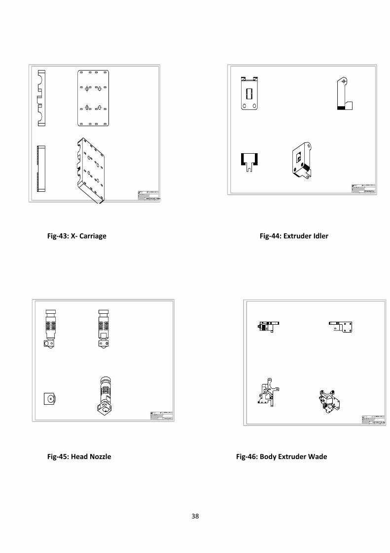
44 43 X- Carriage
45 44 Extruder Idler
46 45 Head Nozzle
47 46 Body Extruder Wade
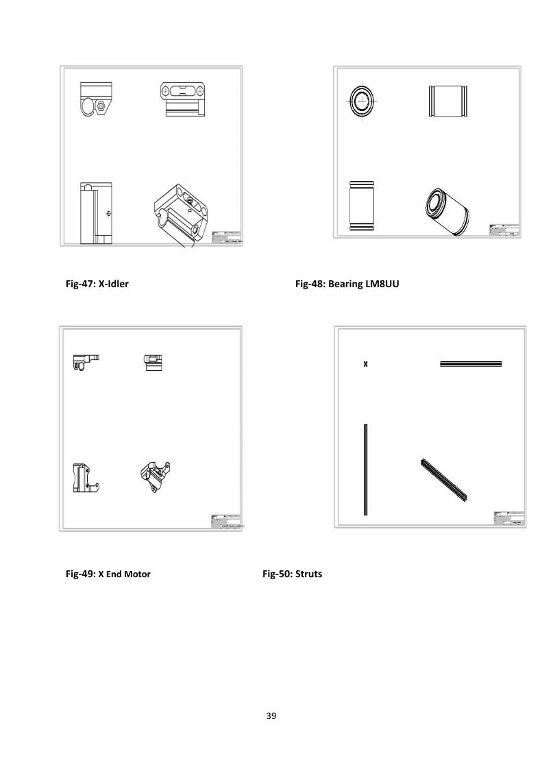
48 47 X-Idler
49 48 Bearing LM8UU
50 49 X End Motor
51 50 Struts
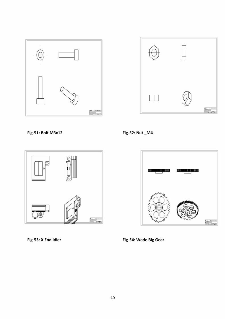
52 51 Bolt
53 52 Nut
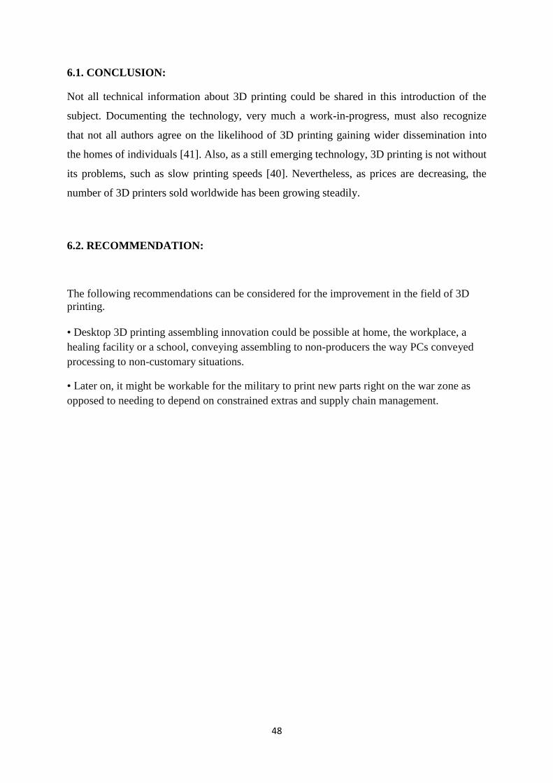
54 53 X End Idler
55 54 Wade Big Gear
56 55 Wade Small Gear
57 56 Bracket
58 57 Y- Axle holder
59 58 End Stop Holder
1
MODULE#01
INTRODUCTION
2
1.1. INTRODUCTION:
3D printing called as desktop fabrication. It is a rapid prototyping process whereby a real
object can be created from a 3D design. A 3D printer machine uses a CAD model for rapid
prototyping process. [1]
3D printing is called as desktop fabrication which is a process of prototyping where by a
structure is synthesized from its 3d model. The 3d design is stored in as a STL format!and
after that forwarded to the 3D printer. It can use a wide range of materials such as ABS,PLA,
and composites as well.3D printing is one kind of rapidly developing@and cost optimized
form which is used for rapid prototyping.The 3D printer prints the CAD design layer@by
layer forming a# real object. 3D printing process is derived from inkjet@desktop printers in
which multiple deposit jets and the printing material,! layer by layer derived from the CAD
3D data.3D printing is diversifying and accelerating our life, letting various qualities of
products to be synthesized easier and faster[2].Three dimensional (3D) printing has the
ability to impact the transmission of information in ways similar to the influence of such
earlier technologies as photocopying. This identifies sources of information on 3D printing,
its technology, required software and applications. Along 3D printing, companies are able to
extract and innovate new ideologies and various design replications with no time or tool
expense. 3D printing possibly challenges mass production processes in future. 3D printing
influences many industries, such as automotive, architecture, education, medical, business
and consumer industries [3].
1.1.MOTIVATION FOR THE PRESENT RESEARCH WORK:
Since over a century the visual world of printed scriptures has been dominated by the 2-D
printing methods. Be that easy to read or comprehend but when it comes to imaging of
definite and real life models it is sorely outsourced. Any 3-D model cannot be represented
and displayed easily in a 2-D workplace. The only thing worth mentioning for likable
perception is the rendering of the image. This ushered in the era of the much needed idea of
“3-D” printing.
3
Basically the singular purpose for the division of 3-D printer was to prepare 3-D samples
directly on the bed of the printer. It has been an effective way of manufacturing since many
companies are now opting for this type of method for their production operations.
1.3. OBJECTIVE:
1. To study different methods of 3d printing and their applications.
2. To study the working procedure of each component of a 3d printer and the evolution
of 3d printer.
3. To design and fabricate a 3d printer using tool kit.
1.4. APPLICATION OF 3D PRINTER:
3-D printing was originally developed for rapid prototyping purposes, making less
complicated physical samples. It allowed designers to identify and rectify design flaws
quickly and cheaply, thereby speeding up the product development process and minimizing
commercial risks. Here are some applications of a 3D printer described below:
Aerospace and Automotive sector
With the help of 3-D-printed components which are used for aircrafts and parts are 70% less
weighing but identically tough as conventional parts, indicating cost reduction and carbon
reduction and emissions of unwanted particle. It uses less raw constituents and manufactures
parts which are less weight, complicated but possess more strength [4].
Medicine
Medical sector is one of the most promising areas of usage. It is being applied to face many
medical situations, and develop medical research, also combining the field of “regenerative
medicine”. In 2012, using a 3-D printer, engineers and doctors at Hasselt successfully
experimented the very first patient-specific instrument of prosthetic jaw transplant [4].
Rapid manufacturing:
Advancements in Rapid Prototyping have presented materials those are necessary for final
manufacturing, leading to the possibility of manufactured finished components and parts [5].
4
Mass customization:
Many industries have provided services where people can recreate their desirables
implementing simple web-based customizing software. This now enables customers to
replicate cases of their mobiles. Nokia has displayed the 3D designs of their mobiles so that
owners will be able to recreate their own phone case [5].
1.5. PROCESS OF 3D PRINTING:
3D printing process can be described and defined in the following steps:
CAD Model Creation: Initially, the item to be 3D printed is designed utilizing a Computer-
Aided Design (CAD) software. Solid modelers, for example, CATIA, and SOLID WORKS
have a tendency to represent 3-D objects more precisely than wire-frame modelers, for
example, AutoCAD. This procedure is comparative for the majority of the Rapid Prototyping
building methods [6].
Conversion to STL Format: The different CAD models use different methods to present
solid parts. To have consistency, the stereo lithography format has been followed as the
standard of the 3D printing industry.
Slice the STL File: A preprocessing computer program is done which readies the STL format
going to be built. Numerous programs are there, which permit the user to tweak the model.
The preprocessing program cuts the Stereo lithography model into numerous layers from 0.01
mm to 0.7 mm thickness, in view of the building method. The program likewise makes an
auxiliary structure to help the model amidst of building. Sophisticated structures are bound to
use auxiliary support [7].
Layer by Layer Construction: The fourth step is the actual construction of the part. Using
one of various techniques RP machines build one layer at a time from polymers, or powdered
metal [7].
1.5. LAYOUT OF THESIS:
Chapter 1 Introduction to the research work, its Motivation, objectives of the project,
Application of 3d printer, Process of 3d printing and Layout of the Thesis.
Chapter 2 Literature Review, Methods of printing, History of 3d printer, Overview of Past
5
Research
Chapter 3 Design, specification and fabrication methodology of 3d printer
Chapter 4 Presents the result obtained
Chapter 5 CAD models of different parts of a 3D printer
Chapter 6 Brief Discussion on Future Perspective
Chapter 7 Conclusion and Recommendation
Chapter 8 References
6
MODULE#02
LITERATURE
REVIEW
7
2.1. INTRODUCTION:
The beginning of 3D printing is related to studies of photography, sculpting, and Landscape
design, which took place in America. Much of the technology was not being developed until
the mid-1980s. During this period, 3D printing was known as “RAPIDPROTOTYPING”.
Chuck Hull, of 3D Systems Corporation, manufactured the first usable 3D printer. Later in
the 80’s, Selective Laser Sintering (SLS) technology was synthesized by Dr. Deckard at the
University of Texas during the commencement of project being done by Defense Advanced
Research Projects Agency. In the 1990s, the technology was further improvised with the
advancement of a method that uses UV light to solidify photopolymer, a highly viscous liquid
material [8].In the 20th century, 3D printers were very expensive and were used to print a few
number of products. Most of the printers were owned by scientists and electronics groupies
for research and display. However advancements in the area of 3D printing have allowed for
the design of products to no longer be limited by complex shapes or colors [9].
2.2. PRINTING METHODS:
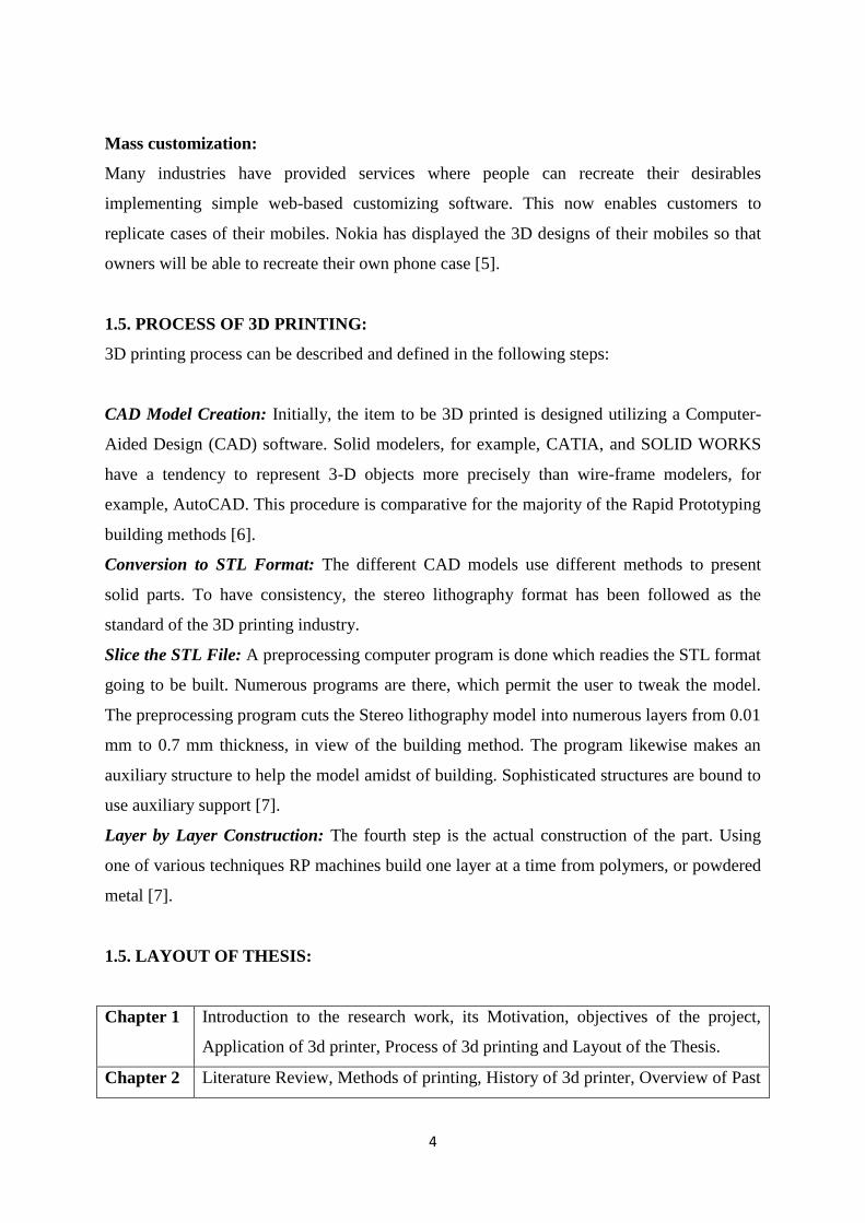
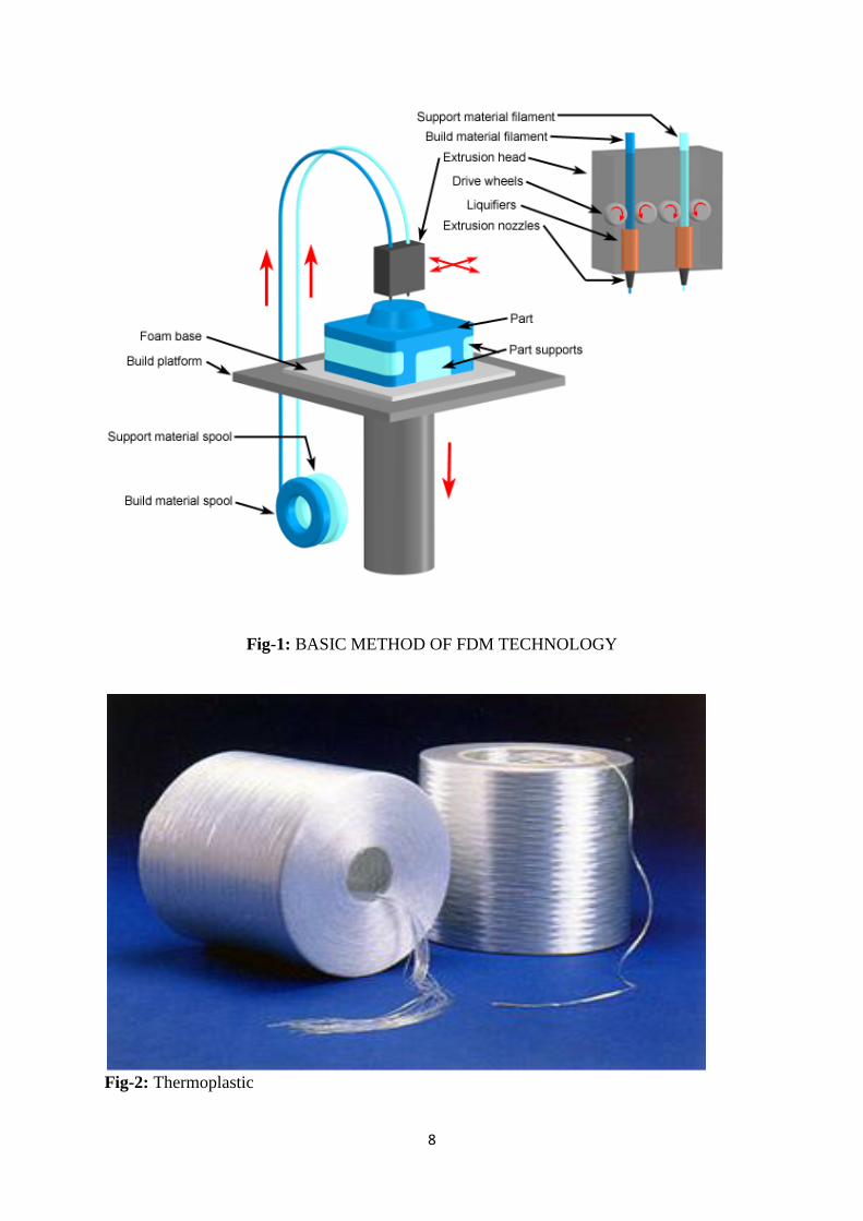
2.2.1. FUSED DEPOSITION MODELLING: In this process the thermoplastics; which constitute ABS (Acrylonitrile butadiene styrene),
wax and nylon were utilized. The introductory venture of the FDM procedure were to warmth
up the thermoplastic constituent until it is at an intertwined state .Then, the 3D printer uses
advanced demonstrating information from a CAD record to create the 3D item layer by layer,
The printers join a much weaker bolster composite. The bolster material goes about as
framework to the test item. This is valuable amid the building procedure when parts have
overhangs that could not bolster it. The thermoplastic for the most part has a filamentous
structure which benefits warmth exchange and serves to move with a print head that
navigates in the x and y bearings. After every layer is printed, a cylinder navigates the stage
beneath (z-hub) the separation of thickness of printed layer. There are numerous benefits of
FDM innovation; it is anything but difficult to control, use, and fix. The expense of the
machine and material are generally low.
8
Fig-1: BASIC METHOD OF FDM TECHNOLOGY
Fig-2: Thermoplastic
9
2.2.2. GRANULAR MATERIAL BINDING (USING HEAT/ ENERGY):
The joining of granular materials involves specifically fusing powder, layer by layer.
The elemental constitution of the powder and binding process relies on the machine.
Fig-3: Granular material binding
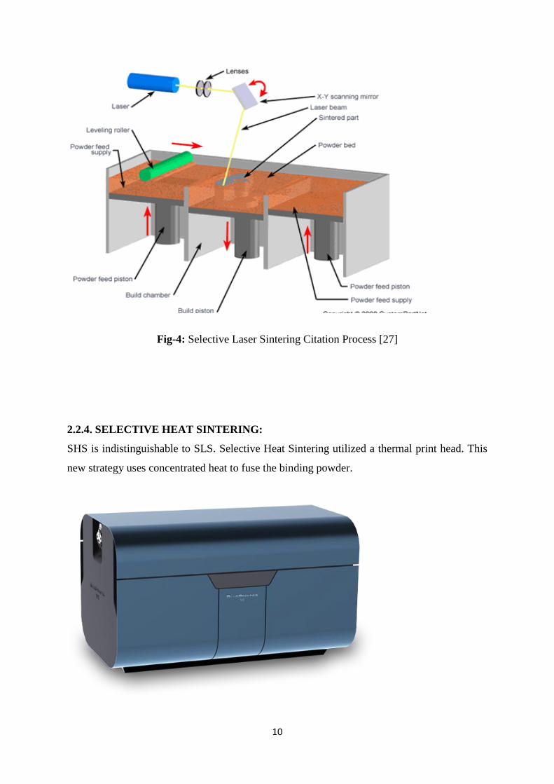
2.2.3. SELECTIVE LASER SINTERING (SLS):
One of the sorts of binding processes is Selective Laser Sintering, or SLS. It utilizes a high-
powered laser to sinter the powder. Once the first layer is made, the whole granular plate, in
which the powder (and the "print") is found, is cut down. As seen in Figure 6, this procedure
is supplemented by the vertical development of a cylinder. Moreover, cylinders are
additionally utilized as a part of a few printers to send the coupling powder up so that the
moving instrument would continue working adequately and the sintering can proceed. A
mirror is integrated to control the laser bar into the foreordained "cut" of the CAD model.
When the greater part of the layers is appropriately sintered, the item is removed from the
build chamber.
10
Fig-4: Selective Laser Sintering Citation Process [27]
2.2.4. SELECTIVE HEAT SINTERING:
SHS is indistinguishable to SLS. Selective Heat Sintering utilized a thermal print head. This
new strategy uses concentrated heat to fuse the binding powder.
11
Fig-5: Illustration of a Blue Printer Citation [28]
Fig-6: A model created by Blue Print Citation [29]
2.2.5. SELECTIVE LASER MELTING (SLM):
SLM is almost as same as SLS. A more powerful laser is generally used. It required more
energy for the metal to be melted.
12
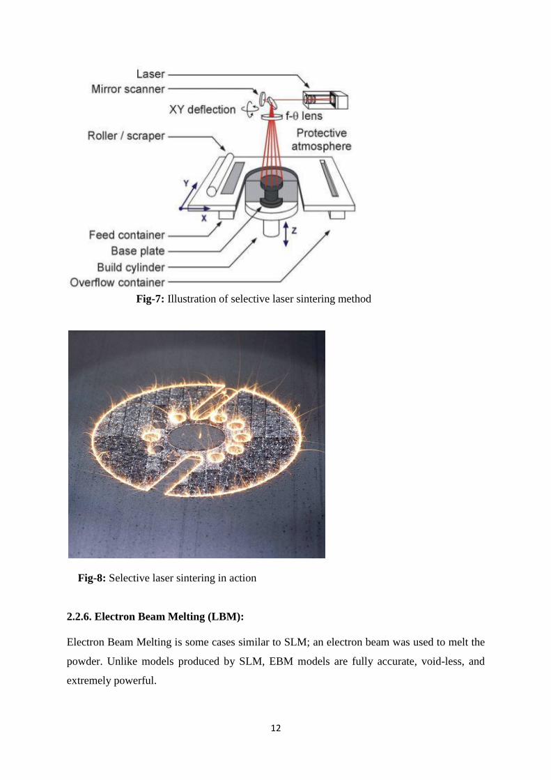
Fig-7: Illustration of selective laser sintering method
Fig-8: Selective laser sintering in action
2.2.6. Electron Beam Melting (LBM):
Electron Beam Melting is some cases similar to SLM; an electron beam was used to melt the
powder. Unlike models produced by SLM, EBM models are fully accurate, void-less, and
extremely powerful.
13
Fig-9: Illustration of an EBM process citation [30]
2.2.7. GRANULAR MATERIAL BINDING (USING BINDING AGENT):
This methodology utilized fluid binding material for the binding procedure of the powder
together, instead of a laser. Zcorp, has a copyright of this innovation around the world. 3D
printing is also called fundamental inkjet printing procedures. As opposed to utilizing paper
like as a part of the instance of a 2D printer, a 3D printer moves the print heads over a bed of
powder whereupon it printed information sent from the product. The fluid binding materials
here utilized is much the same as super glue. Composite material or mortar is utilized as
powder here.
14
Fig-10: Illustration of granular material
2.2.8. Photo Polymerization:
This is an additive manufacturing process. This methodology utilizes UV light for the
hardening of the photograph polymer. There are diverse sorts of photopolymers which are
accessible today. Photograph polymerization is really same as FDM and Granular Material
binding process. The fundamental contrasts are the material sand the system utilized for the
printing systems.
2.2.9. Stereo Lithography:
A stereo lithographic printer is regularly known as a SLA. A perforated platform was put just
beneath the surface of a carriage of fluid polymer.
15
Fig- 11: Illustration of SLA Platform [31]
The UV-treatable fluid solidifies quick, shaping the essential layer of the 3D-printed item.
Next, the stage was brought down, uncovering another surface layer of the fluid substance.
This procedure is rehashed more till the whole question is framed and is completely
submerged in the tank [10]. Regularly, the utilization of the UV stove issued for the ensuing
cure of the photograph polymer.
16
Fig- 12: Illustration of SLA process
2.2.10. DLP Projecting:
DLP (Digital Light Processing) is one kind of stereo lithographic procedure. It utilizes a
projector to solidify a layer of photopolymer at once, as opposed to utilizing a laser for the
following of distinctive layers. A mirror was most normally used to position and size the
replication precisely onto layer of photopolymer.
Fig- 13: Illustration of DLP Projection
17
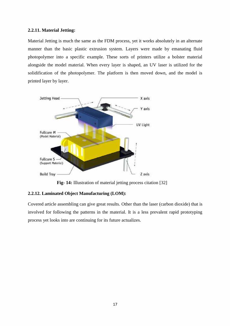
2.2.11. Material Jetting:
Material Jetting is much the same as the FDM process, yet it works absolutely in an alternate
manner than the basic plastic extrusion system. Layers were made by emanating fluid
photopolymer into a specific example. These sorts of printers utilize a bolster material
alongside the model material. When every layer is shaped, an UV laser is utilized for the
solidification of the photopolymer. The platform is then moved down, and the model is
printed layer by layer.
Fig- 14: Illustration of material jetting process citation [32]
2.2.12. Laminated Object Manufacturing (LOM):
Covered article assembling can give great results. Other than the laser (carbon dioxide) that is
involved for following the patterns in the material. It is a less prevalent rapid prototyping
process yet looks into are continuing for its future actualizes.
18
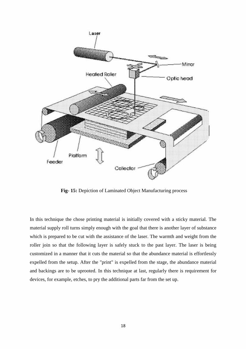
Fig- 15: Depiction of Laminated Object Manufacturing process
In this technique the chose printing material is initially covered with a sticky material. The
material supply roll turns simply enough with the goal that there is another layer of substance
which is prepared to be cut with the assistance of the laser. The warmth and weight from the
roller join so that the following layer is safely stuck to the past layer. The laser is being
customized in a manner that it cuts the material so that the abundance material is effortlessly
expelled from the setup. After the "print" is expelled from the stage, the abundance material
and backings are to be uprooted. In this technique at last, regularly there is requirement for
devices, for example, etches, to pry the additional parts far from the set up.
19
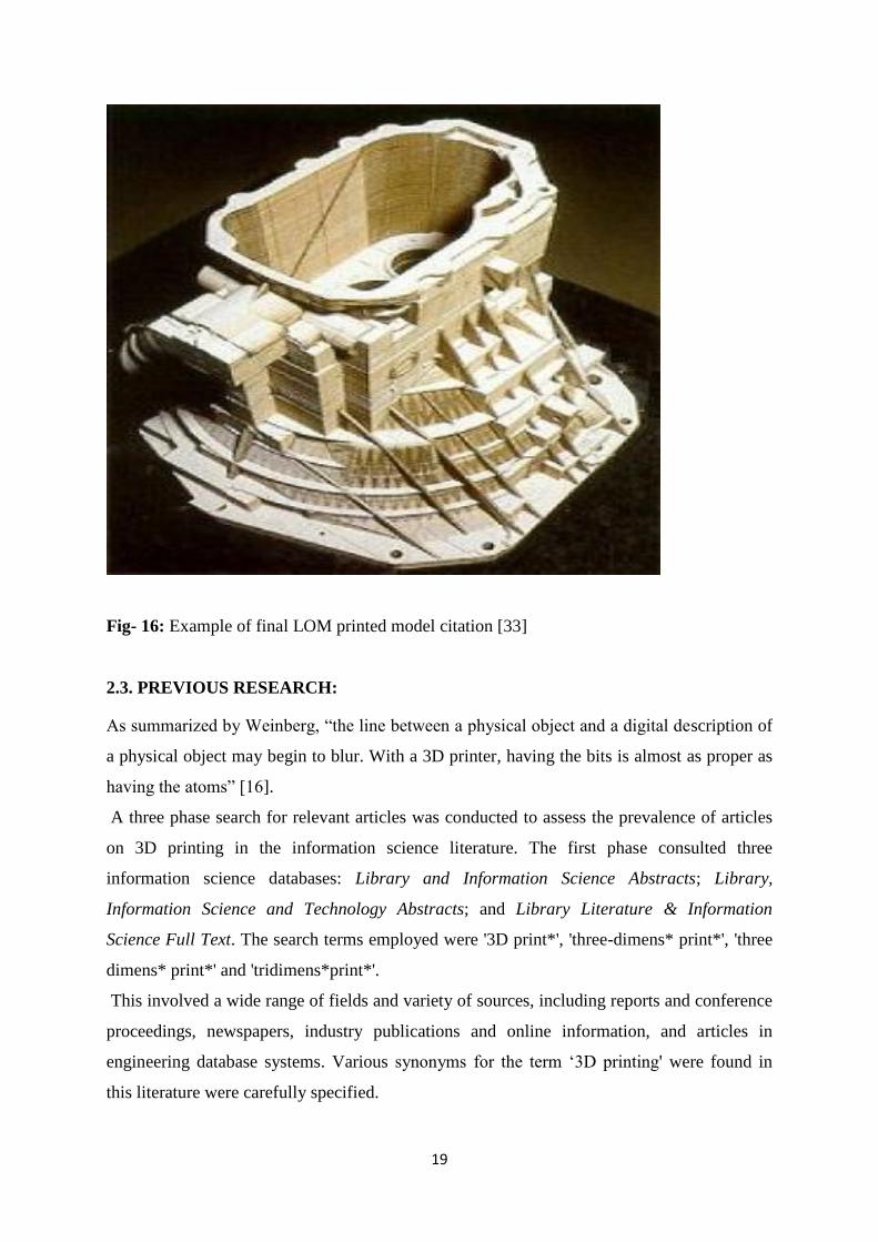
Fig- 16: Example of final LOM printed model citation [33]
2.3. PREVIOUS RESEARCH:
As summarized by Weinberg, “the line between a physical object and a digital description of
a physical object may begin to blur. With a 3D printer, having the bits is almost as proper as
having the atoms” [16].
A three phase search for relevant articles was conducted to assess the prevalence of articles
on 3D printing in the information science literature. The first phase consulted three
information science databases: Library and Information Science Abstracts; Library,
Information Science and Technology Abstracts; and Library Literature & Information
Science Full Text. The search terms employed were '3D print*', 'three-dimens* print*', 'three
dimens* print*' and 'tridimens*print*'.
This involved a wide range of fields and variety of sources, including reports and conference
proceedings, newspapers, industry publications and online information, and articles in
engineering database systems. Various synonyms for the term ‘3D printing' were found in
this literature were carefully specified.
20
Results of the three literature searches depict that most of the relevant material on 3D printing
has been published within the last several years, including many sources less than two to
three years old. As a technology, however, 3D printing has been around for some time, and
commercial printers “have existed for years” [17] [19] [20].
Bradshaw et al. [10] confirm that the first patent was deposited in 1977. One reason for the
recent nature of most of the literature is that prices for 3D printers have dropped sufficiently
that individuals can now afford to purchase their own equipment [8] [11] [13] [20].
This search concluded only four additional results. Two of these articles [21] [22] were by the
same author, giving a brief assessment of one commercial 3D printer and of a particular piece
of modelling software which was being used at that time for rapid prototyping. Another [23]
explained combining two databases to give a 3D printable file of the outline of buildings in
Norway. The three articles were very focused on their specific topics from which none of
them clearly mentioned about the usefulness of the 3D printing systems.
Although also narrowly focused, the fourth article [24] discusses the use of 3D scanners and a
3D printer to create replicas of wooden stamps and replicas. The article concludes by
explaining that the stamps were now easier to share with other libraries and museums.
Articles relevant to the information implications of 3D printing technology were also
discovered in the more general, were conducted in the second phase of the literature review.
A kinematic library was identified which has made 3D printable files of kinetic models
available online [25].
The metadata for reflecting on the classification and cataloguing of 3D printable files, it did
not appear to be systematically maintained, and many of the supplied links are broken [26].
Ingole et al. [27] make some valuable observations about the need for more formalized
standards for 3D printing and explains some of the difficulties associated with the different
standards associated with commercial machineries.
The second engineering article, by Mortara et al. [28] reveals an awareness of such important
classification concepts as a classification, but the proposed classification scheme was clearly
aimed at engineers, and it would not be easy to use for publicly accessible firms.
21
2.4. HISTORY OF 3-D PRINTING:
3D printing technologies first became visible in the 1980’s; at that time they were called
Rapid Prototyping (RP) technologies. The very first patent application for RP technology was
filed by a Dr Kodama in 1985. Hull became the co-founder of the 3D corporations which is
one of the largest and most major companies in the field of 3D printing and rapid
prototyping.
The primary business Rapid prototyping framework, the SLA-1, was presented in 1987 The
patent in regards to the FDM innovation was at initially issued to Stratasys in 1992. After a
wasting with the stereo lithography process, EOS' R&D center was chiefly on the laser
sintering (LS) process, which got reinforced step by step. Today, the EOS frameworks are all
around perceived the world over for their gainful and subjective yield for mechanical
prototyping and enthusiastic applications in the 3D printing part. The organization's metal
laser sintering (MLS) procedure came about because of an undertaking with a bureau of
Electrolux Finland, which was later obtained by the organization EOS in the year 1993.
22
MODULE#03
DESIGN, SPECIFICATION
AND FABRICATION OF
3D PRINTER
23
3.1. EXPERIMENT AND METHODOLOGY:
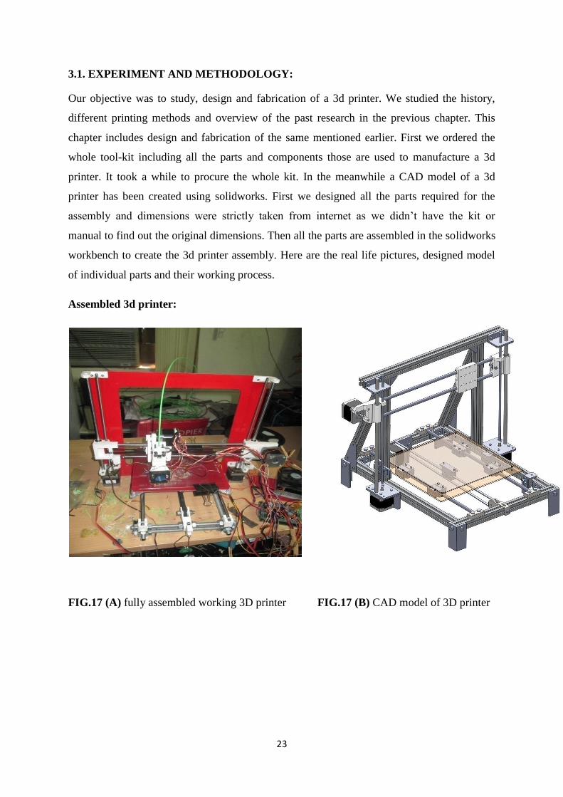
Our objective was to study, design and fabrication of a 3d printer. We studied the history,
different printing methods and overview of the past research in the previous chapter. This
chapter includes design and fabrication of the same mentioned earlier. First we ordered the
whole tool-kit including all the parts and components those are used to manufacture a 3d
printer. It took a while to procure the whole kit. In the meanwhile a CAD model of a 3d
printer has been created using solidworks. First we designed all the parts required for the
assembly and dimensions were strictly taken from internet as we didn’t have the kit or
manual to find out the original dimensions. Then all the parts are assembled in the solidworks
workbench to create the 3d printer assembly. Here are the real life pictures, designed model
of individual parts and their working process.
Assembled 3d printer:
FIG.17 (A) fully assembled working 3D printer FIG.17 (B) CAD model of 3D printer
24
3.2. Different parts of a 3d printer:
Various components of 3D printers are: Frame, Y-axis and bushing, Extruder, printplate,
stepper motors, Z-axis and Y- axis, X-carriage, Electronics parts, stepper motor controllers
and end-stops [42].
Description of a 3d printer parts:
Frame: The frame provides the printer its property regarding stiffness. The three axes of the
printer are added to frame. The frame consists of threaded rods combined together with
printed parts. Aside from the vertex the edge likewise comprises of printed parts to hold and
recreate the Y-axis and Z-axis. On the upper left and upper right we observe the printed parts
that hold the stepper motors of the Z-axis.
FIG.18 Empty 3d printer Frame
Y-axis and Bushing:
From picture 19 we can see the print base plate is collected on the Y-axis smooth poles. The
Y-axis has one degree of freedom i.e. it can move between the front and back of the casing.
The Y-axis is controlled by a belt drive appended to a stepper motor with pulley. The print
base plate has four bushings joined to it. Bushings are only plain bearing. They slide over
smooth bars and give right around zero rubbing when going here and there the poles. On the
3d printer, the bushings climb and down the smooth poles taking after a virtual line on the
bars. Linear Bearing has little balls inside and gives free and smooth movement in one course
25
just. Metal bushings are by and large comprised of metal which have low erosion and is self-
greasing up too. 3D printer outline utilizing direct course by and large favor LM8UU metal
orientation. The standard 3D printer utilizes bushings [42].
Fig-19: 3D printer frame with y-axis installed
Fig-20: Brass Bushing inserted in printed parts
Fig-21: Printed Linear Bearing
26
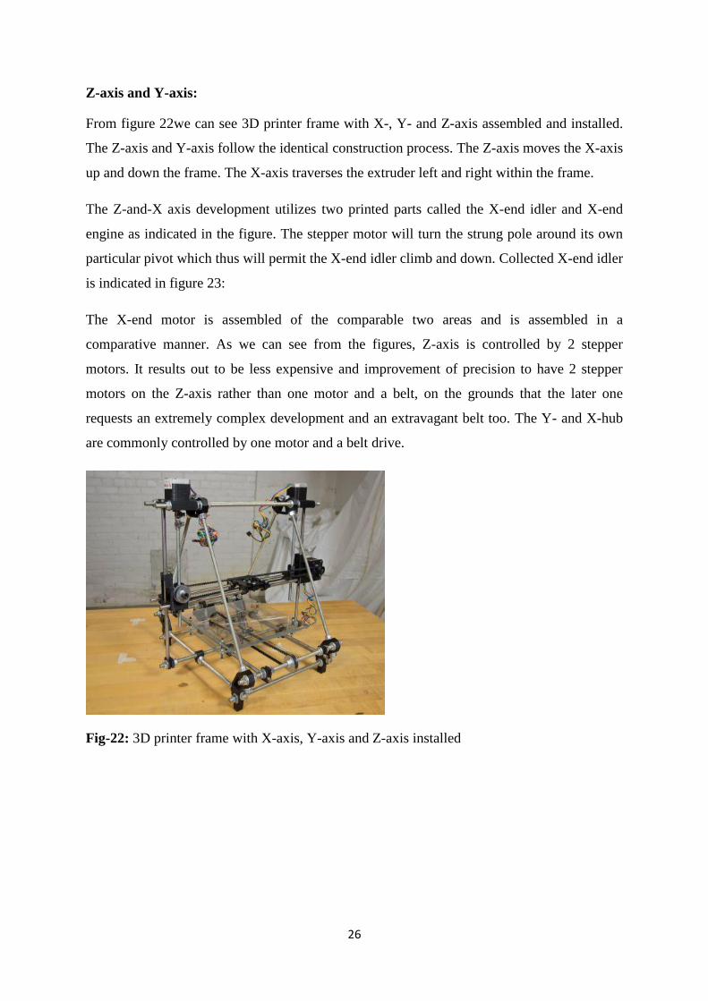
Z-axis and Y-axis:
From figure 22we can see 3D printer frame with X-, Y- and Z-axis assembled and installed.
The Z-axis and Y-axis follow the identical construction process. The Z-axis moves the X-axis
up and down the frame. The X-axis traverses the extruder left and right within the frame.
The Z-and-X axis development utilizes two printed parts called the X-end idler and X-end
engine as indicated in the figure. The stepper motor will turn the strung pole around its own
particular pivot which thus will permit the X-end idler climb and down. Collected X-end idler
is indicated in figure 23:
The X-end motor is assembled of the comparable two areas and is assembled in a
comparative manner. As we can see from the figures, Z-axis is controlled by 2 stepper
motors. It results out to be less expensive and improvement of precision to have 2 stepper
motors on the Z-axis rather than one motor and a belt, on the grounds that the later one
requests an extremely complex development and an extravagant belt too. The Y- and X-hub
are commonly controlled by one motor and a belt drive.
Fig-22: 3D printer frame with X-axis, Y-axis and Z-axis installed
27
Fig-23: X-end idler part on LHS and X-end motor part on RHS
Fig-24: Assembled X-end idler
EXTRUDER:
Fig-25: Wade’s geared extruder
28
The 3D printer is generally assembled with a Wade’s geared extruder. This extruder contains
two parts: a cold top part which feeds or provides the plastic filament and a hot bottom part
which helps in melting and in turn the plastic gets extruded. These two parts, usually known
as the Wade extruder (the cold part) and the hot-end (the hot part).
The Wade extruder holds of a large gear which is driven by a stepper motor. This large gear
drives a bolt, which extracts the plastic filament and pushes it into the hot-end where the
plastic starts melting.
The hot-end is generally a bolt made up of metal with a gap penetrated down the vertical
pivot. This screw, otherwise called a heater barrel. At the tip of the heated barrel, the way out
opening diminishes down to under 1mm from 3mm [42].
Two techniques are utilized to warmth the hot-end: utilizing resistor or NiChrome wire. A
NiChrome wire is far too simple .A resistor needs a heater block which will be turned onto
the heater barrel.
Fig-26: shows a heater block with a resistor installed.
Fig-27: Heater barrel wrapped with nichrome wire
29
A hot-end have three basic parts: Thermistor, to discover the temperature, a heat barrier to
keep the hot-end far from the cool end, the chilly end will dissolve without heat barrier and a
spout which permits the dissolved plastic to be flown out of the heater barrel.
A connection has been made in the middle of thermistor and the gadgets board - only like the
resistor or NiChrome wire – and this helps the hardware to quantify and choose the
temperature of the warmer barrel. The radiator barrel meets expectations at a temperature
configurationally, and that temperature could be come to utilizing a thermistor Figure
28shows a heater barrel with nozzle:
Fig-28: Heater Barrel
X-CARRIAGE: The amassed extruder alongside cold end, heat barrier and hot-end is fitted
on the X-axis carriage. Figure 29 beneath demonstrates an amassed X-axis with two smooth
poles, a X-end idler and a X-end motor parts and the printed X-carriage:
Fig-29: Assembled X-axis with two smooth rods, the X-end idler and X-end motor printed
parts and the printed X-carriage:
The movement of the X-carriage is taken care by one stepper motor and a belt.
30
Fig-30: Assembled Wade’s geared extruder mounted on the X-carriage
PRINT PLATE:
Printed parts are intended to be imprinted on the print plate. The three axes move with respect
to one another so that the nozzle can be set simply over the print plate for the printing reason
in a range given by the particular of the print plate.
The print plate for the most part constitutes two plates: the print base plate which is fitted and
mounted on the X-pivot smooth poles by utilizing a bushing or a direct bearing and the print
top plate which is mounted on the base plate and in this way, shapes the print surface.
.
Fig-31: Top print plate stack on bottom print plate
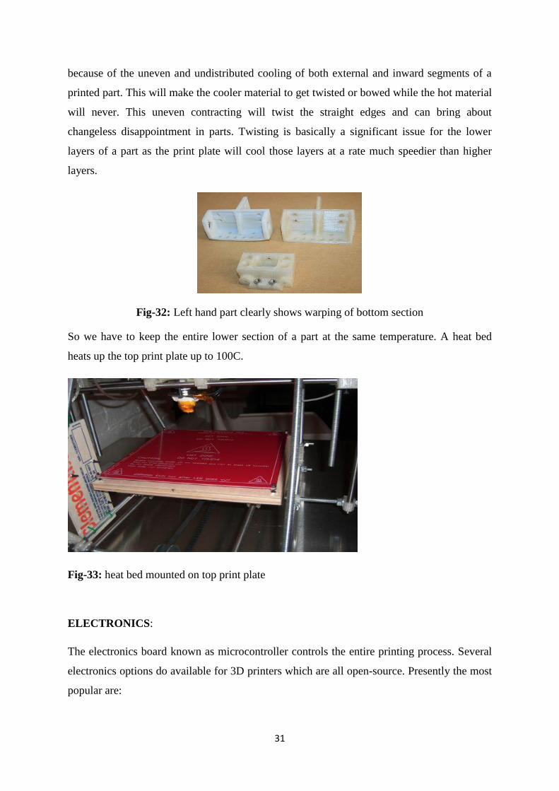
Another vital part of a 3D printer is the heated bed. These altogether cutoff the measure of
twisting on the printed parts, particularly on the lower layers. Distorting is brought on
31
because of the uneven and undistributed cooling of both external and inward segments of a
printed part. This will make the cooler material to get twisted or bowed while the hot material
will never. This uneven contracting will twist the straight edges and can bring about
changeless disappointment in parts. Twisting is basically a significant issue for the lower
layers of a part as the print plate will cool those layers at a rate much speedier than higher
layers.
Fig-32: Left hand part clearly shows warping of bottom section
So we have to keep the entire lower section of a part at the same temperature. A heat bed
heats up the top print plate up to 100C.
Fig-33: heat bed mounted on top print plate
ELECTRONICS:
The electronics board known as microcontroller controls the entire printing process. Several
electronics options do available for 3D printers which are all open-source. Presently the most
popular are:
32
RAMPS, a DIY shield board for Arduino MEGA
Sanguinololu, a DIY board with microprocessor on board
Functions of a 3d printer electronics board:
Processes G-code instructions.
Controls and regulates the four stepper motor controllers where both Z-axis motors
are essentially connected to the same stepper motor controller.
Monitors the end-stops
Controls the temperature of the heated bed
The electronics board is connected to the PC using a USB-to-serial converter.
STEPPER MOTOR:
There are five stepper motors used in the 3D printer are One to control the Y-axis, One to
control the X-axis, Two to control the Z-axis, One to control the extruder.
STEPPER MOTOR CONTROLLER:
Controlling a bipolar stepper motor is truly muddled, particularly in the matter of smaller
scale venturing mode. Unipolar stepper motors are much simpler to control however they
give lesser torque given the motor size is same. Exceptionally outlined stepper motor
controllers are being utilized to assume control over the troubles of directing a stepper motor.
With the assistance of such controller stand out small scale step can be made. Consequently
controlling of a stepper motor has been rearranged.
END STOPS:
While printing an object, all three axes need to be altered the initial position to their starting
one. This is known as the zero position of any Cartesian robot. The axes can’t move any
further than zero.
To acquire this, three end stops are to be installed one for each axis. An end stop needs to be
mounted at such a position where the axis shouldn’t go beyond:
33
For the X-axis, this ought to be the position where the nozzle achieves the left-hand side of
the print plate, For the Y-axis this ought to be on the posterior of the pivot such that the print
plate is permitted to move to the back sufficiently far so that the nozzle winds up on the
forward of the print plate, For the Z-axis position ought to be the place the nozzle scarcely
touches the print plate.
In a 3d printer 2 SMPS ,1 voltage converter,1 micro cotroller,5 stepper motors and 2 belt
drives are considered as important components. After all the connection is made, AC power
supply is given to the SMPS. Later this voltage is supplied to the voltage converter which is
basically a step down transformer which reduces the voltage up to a noticeable level. This
reduced voltage is just high enough to propel a 3d printer and this voltage is supplied to the
micro controller. All the motors are connected to the micro controller which sends
appropriate signal to each component for it to work.
Some of the parameters those need to be valued before printing a product using 3d printer
are:
Bed Temperature, Extruder Temperature, Feed Rate, Flow Rate .Bed Temperature shouldn’t
exceed the melting temperature of the filaments used. A number of fans are required for the
cooling purpose of the bed and for all the metallic parts of the printer.
34
3.3.WORK DONE:
Here are some images of a working home-built 3D printer and its components:
Fig-34: Wade’s geared wheel Fig-35: X-end motor &belt drive, bushing,
(Extruder Assembly)
35
Fig-36: Assembled Microcontroller Fig-37: Cooling fan connected to the microcontroller
Fig-38: Voltage converter (SMPS)
36
MODULE#04
CAD MODELS OF
DIFFERENT PARTS OF A
3D PRINTER
37
4.1. DIFFERENT VIEWS OF THE COMPONENTS:
Here are some images representing the Left side view, Right side view, Top view and
Isometric view of some essential components of a 3D printer.