NASA CR-72567 UARL Ha910721 FINAL PROGRESS REPORT STUDY OF CATALYTIC REACTORS FOR HYDROGEN-OXYGEN IGNITION by Arthur S. Kesten prepared for NATIONAL AERONAUTICS AND SPACE ADMINISTRATION CONTRACT NASW-1795 United Flircraft Research Laboratories U . UNITED AIRCRAFT CORPORATlON https://ntrs.nasa.gov/search.jsp?R=19690031855 2020-05-22T05:49:50+00:00Z
Transcript
NASA CR-72567 UARL Ha910721
FINAL PROGRESS REPORT
STUDY OF CATALYTIC REACTORS FOR HYDROGEN-OXYGEN IGNITION
Portions of this document have been judged by the Clearinghouse to be of poor reproduction quality and not fully legible. However, i n a n effort to make as much information a s possible available fo the public, the Clearinghouse sells this document with the understanding that i f the a e r is not satisfied, the document may be returned for refund.
If you return this document, please include this notice togetherwith the IBM order card (label) to:
An analytical study of a catalytic ignition system to promote hydrogen-oxygen combustion was performed in order to establish procedures capable of predicting the steady-state behavior of the system. The study included the development of a computer program which is used to calculate the steady-state axial temperature and reactant concentration profiles in typical reaction chamber configurations. The computer program is based upon a mathematical model of the reactor system which considers both thermal and catalytic reaction of hydrogen and oxygen, along with simultaneous heat and mass transfer between the free-gas phase and the gas within the pores of the catalyst pellets. The computer program has been used to evaluate the effects of chamber pressure, feed temperature, stoichiometry, helium dilution, mass flow rate and catalyst bed configuration on the steady-state behavior of the reactor system.
i
This work was performed by United Aircraft Research Laboratories f o r the National Aeronautics and Space Administration under Contract NASW-1795 i n i t i a t ed August 28, 1968.
Included among those who cooperated in performance of the work under Contract EASW-1795 were Dr. A. S. Kesten, Program Manager, D r . W. G. Burwell, Chief, Kinetics and Thermal Sciences Section, Mrs. E. Smith, and M r . D. B. Smith of UARL.
This work was conducted under program management of the NASA Lewis Research Center and the Technical Manager was Mr. P. N. Herr, NASA Lewis Research Center, Cleveland, Ohio.
ii
R e p o r t H910721
Study of Catalytic Reactors f o r
Hydrogen-Oyygen Ignition
Final Progress Report
August 28, 1968 - May 28, 1969
Contract NASW-1795
SUMMARY
The Research Laboratories of United Aircraft Corporation der contract u$1 with the National Aeronautics and Space Administration a re performing an analy- t i c a l study of a ca ta ly t ic igni t ion system t o promote hydrogen-oxygen combustion. This f i n a l technical report, summarizes the first phase o f , t h i s work which wzis performed under Contract NASW-1795 from August 28, 1968 t o May 28, 1969. Work during t h i s period has included the development of a c a p u t e r program which is used t o calculate the steady-state axial temperature and reactant concentration prof i les i n typ ica l reaction chamber configurations, The computer program is based upon a mathematical model of the reactor system which considers botn thermal and ca ta ly t ic reaction of hydrogen and oxygen, along with simultaneous heat and mass t ransfer between the free-gas phase and the gas within the pores of the catalyst pel le ts . within hot catalyst par t ic les might condense or freeze i n the colder bulk gas phase has been taken in to account i n the model. evaluate the effects of chamber pressure, feed temperature, stoichiometry, helium dilution, mass flow ra t e and catalyst bed configuration on the steady-state behavior of the reactor system.
The poss ib i l i ty t ha t water vapor produced by ca ta ly t ic reaction
The computer program has been used t o
1
H910721
Effecklve design of a ca ta ly t ic igni t ion system t o promote hydrogen-oxygen combustion requires the capabili ty for predicting the e f fec ts of the design and operating character is t ics of the reactor system on the t ransient and steady- state performance of the system. the f e a s i b i l i t y of using catalysts t o promote hydrogen-oxygen combustion had been demonstrated i n a number of experimental investigations (Refs. 1, 2 and 3). investigations did not adequately assess the e f fec ts on reactor performance of such parameters as chamber pressure, feed temperature, stoichiometry, mass flow rate , and catalyst s ize distribution. Nor did these investigations adequantely specify igni t ion limits or igni t ion delay times. TCI achieve t h i s information, a compre- hensive theoret ical analysis is required which considers the simultaneous processes of heat t ransfer , diffusion, and chemical reaction i n the catalyt ic reactor. Such an analysis had already been performed a t UAF& f o r ca ta ly t ic reactors which promote hydrazine decomposition (Refs. 4, 5 and 6 ) . t o predict both steady-state and t ransient performance of these reactors. Prelimin- ary investigations a t UARZ; indicated t h a t these computer programs could be extended t o predict the steady-state and t ransient performance of the hydrogen-oqygen system.
This general capabili ty did not ex i s t although
These
Compter programs had been developed
Based upon the above investigations,a comprehensive analyt ical program directed i n i t i a l l y a t the steady-state analysis was formulated with the objectives of (a) extending the analysis f o r predicting the steady-state temperature and concentration dis t r ibut ions i n monopropellant hydrazine ca ta ly t ic reactors t o the bipropellant hydrogen-oxygen system, (b) developing a computer program based on t h i s extended analysis, ( e ) performing calculations using t h i s computer program t o demonstrate the e f fec ts of various system parameters on the steady-state perfor- mance of the reactor, and thus t o define the regimes i n which ignition i s possible, and ( d ) defining the processes controlling the overall reaction r a t e i n different. regions of the reaction system i n order t o f a c i l i t a t e adaptation of the t ransient anzlysis of hydrazine ca ta ly t ic reactor t o the hydrogen-oxygen system. i s described i n d e t a i l i n succeeding sections of t h i s report.
This e f fo r t
E910721
Steady-State Model of Hydrogen-Oxygen Catalytic Ignition System
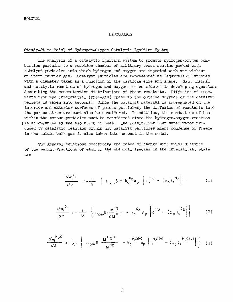
The analysis of a ca ta ly t ic igni t ion system t o promote hydrogen-oxygen com- bustion pertains t o a reaction chamber of a rb i t ra ry cross section packed w i t h catalyst par t ic les in to which hydrogen and oxygen are injected with and without an i n e r t ca r r i e r gas. with a diameter taken as a function of the par t ic le s i ze and shape. and ca ta ly t ic reaction of hydrogen and oxygen a re considered i n developing equations describing the concentration dis t r ibut ions of these reactants. Diffusion of reac- t an t s from the i n t e r s t i t i a l (free-gas) phase t o the outside surface of the catalyst pe l le t s i s taken in to account. i n t e r io r and e'xterior surfaces of pomus par t ic les , the diffusion of reactants into the porous s t ructure must a l so be considered. within the porous par t ic les must be considered since the hydrogen-oxygen reaction
duced by ca ta ly t ic reaction within hot catalyst par t ic les might condense o r freeze i n the colder bulk gas is also taken in to account i n the model.
Catalyst par t ic les a re represented as "equivalent" spheres Both thermal
Since the catalyst material i s impregnated on the
I n addition, the conduction of heat
$ i s accompanied by the evolution of heat. The possibi l i ty t ha t water vapor pro-
The general equations describing the rates of change with axial distance of the weight-fractions of each of the chemical species i n the i n t e r s t i t i a l phase are
d w i H2
d z G - = - - ' I 'hornZ; -t kc H 2 A p [ C l H 2 -
3
H910721
He (4) dwi
= o dz
The rates of change of species concentrations with axial distance a re then given by
de, dw, j 'pi + WI - d z = P I 7 dz
( 5 )
and
Heat and mass t ransfer coefficients may be estimated from (Ref. 7 )
In the entrance region of the reactor, where the temperature i n the i n t e r s t i t i a l phase i s low enough t o cause freezing of the water vapor diffusing out of the catalyst par t ic les , the change i n enthalpy of the i n t e r s t i t i a l phase with ax ia l distance i s
4
H93.0721
given by
In t h i s "ice region"
HzO (5) dwiH20 - dwi
dz d2 - - -
In the higher temperature, "ice-liquid region" of the reactor, the change i n enthalpy of the i n t e r s t i t i a l phase with distance is given by
(11)
and the rates of change of ice and l iquid weight-fractions are given by
5
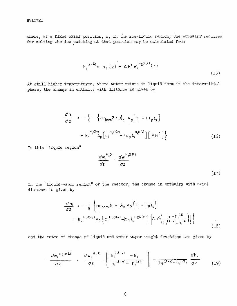
where, a t a fixed ax ia l position, z, i n the ice-liquid region, the enthalpy required for melting the ice exis t ing a t tha t posit ion may be calculated from
A t s t i l l higher temperatures, where water ex is t s i n l iquid f o m i n the i n t e r s t i t i a l phase, the change i n enthalpy with distance i s given by
In t h i s "liquid region"
In the "liquid-vapor region" of the reactor, the change i n enthalpy with axial distance i s given by
and the rates of change of l iquid and water vapor weight-fractions a re given by
dz uz
H910721
where, a t a fixed a-al posit ion i n t h i s region, the enthalpy required f o r vaporizing the l iqu id exis t ing a t that posit ion may be calculated from
I n the high temperature, a l l vapor, region of the reactor, t he change i n enthalpy with distance is given by
I - - d h i - - - ( H l h o m 8 i- & A D [T I - ( T P ) ~ ] } dz G
and
Species concentrations and temperatures a t the outside surfaces of the catalyst gar t ic les can pe determined, together with the concentration and temperature prof i les throughout the par t ic les , using an in tegra l equation method described i n Appendix I. It should be noted t h a t under steady-state conditions, successful opemtion of the hydrogen-oxygen ca ta ly t ic ign i t ion system requires tha t water produced by ca-r,alyLic reaction remain as vapor within the ca ta lys t par t ic les , Should the p a r t i a l pressurc of water vapor exceed the vapor pressure a t any point within a ca ta lys t pe l le t , condensation (or f reezwg) of m t e r vapor within the porous s t ructure would "poison" the ca ta lys t and prevent fu r the r reaction.
F in i te difference methods have been used t o program f o r d i g i t a l computation the d i f f e ren t i a l equations describing the changes with axial distance of enthalpy and species concentrations i n the in te rs t i t i a l phase, These equations s r e solved
7
simultaneously with the integral ' equations describing the diffusional processes within the pores of the catalyst par t ic les a t each of a number of ax ia l positions i n the reaction chamber. The number and s izes of axial increments i n to which the reactor is divided are determined re la t ive t o the loca l ra tes of change of enthalpy of the i n t e r s t i t i a l phase with ax ia l distance. contained in Appendix 11.
A l i s t i n g of the computer program i s
Kinetics Information
A number of investigators have assembed kinet ics information f o r the'gas phase reaction of hydrogen and oxygen (Refs. 8, 9 and 10). ra tes are a l l quite low f o r even the highest temperatures of i n t e re s t here, the activation energies and orders of reaction reported i n these studies a re i n serious disagreement. A rate expression which agrees f a i r l y well with the data reported i n Ref; 10 and with the overal l order of the reaction reported i n Ref. 8 was choseri f o r use i n t h i s work, since the resu l t s given i n Ref. 10 were obtained i n a reactor similar t o the one of i n t e re s t here. The expression i s
While the reported reaction
rhm = 0,16 x 10¹⁴ ci% c p 2 e-35y800/Ti l b s I$ reacted/fd-sec
where the concentrations are i n lb / f t3 (kg /m3) and Ti is i n deg R (deg K ) .
Estimating the chemical kinet ic ra te l a w and constants appropriate t o the ca ta ly t ic reaction of hydrogen and oxygen is quite d i f f i cu l t . number of experimental investigations have been conducted with t h i s objective, the resu l t s of various investigators d i f f e r considerably f o r diverse conditions of con- centration, temperature and catalyst . These resu l t s indicate that , even for low temperature reaction on platinum family m e t a l s , the reaction mechanism changes with gas composition. Reaction of chemisorbed oxygen with hydrogen molecules i n the gas phase appears t o be the rate-controlling s tep i n systems where excess oxygen i s present, while t h i s re la t ively slow reaction does not seem t o influence the overall reaction r a t e i n systems containing excess hydrogen. For low tempera- tGre, hy?rc,gcn- r l c h systarns,Viller and Deans (Ref. 11) and Maymo and Smith (Rzf. 12) report on act ivat ion energy of approximately 5.5 kcal and an order of reaction with respect t o oxygen of 0.8. I n the lat ter study, the r a t e of reaction was found t o be uninfluenced by the presence of w a t e r i n the vapor phase. No work was done i n these studies to estimate the order of reaction with respect t o hydrogen. In the present work the resu l t s of Refs. 11 and 12 were used together with an assumed first order dependence of reaction rate on hydrogen concentration t o get a reaction r a t e expression of the form*:
Although 8 substant ia l
*The assumption of? f i r s t order kinetics with respect t o hydrogen should not introduce any great e r ror i n the ra te expression so long as the expression is applied t o a e y s k r . 1 where hydrogen is present i n large excess.
8
where Tp is i n deg R (deg K). structit?? of the platinum family metal employed.
The rate constant, CY , is specif ic t o the type and
It was original ly intended t o estimate CY f o r a par t icrhar catalyst by using the steady-state program t o f ind the value of a f o r wh calculated axial tempera- t u re prof i les exhibited the best agreement with temperatures measured i n engine t e s t s being performed by TRW. Although these temperature measurements a re not yet avail- able, preliminary t e s t resu l t s (Ref. 13) indicate that, under steady-state conditions, reaction on Shell 405 catalyst may be so fast tha t the hydrogen-oxygen reaction mzy be diffusion-controlled throughout the reactor. That is, the value of a f o r the Shell catalyst may be so high that reaction occurs essent ia l ly instanteously upon contact of the reactants w i t h the catalyst surface.
Results of Calculations
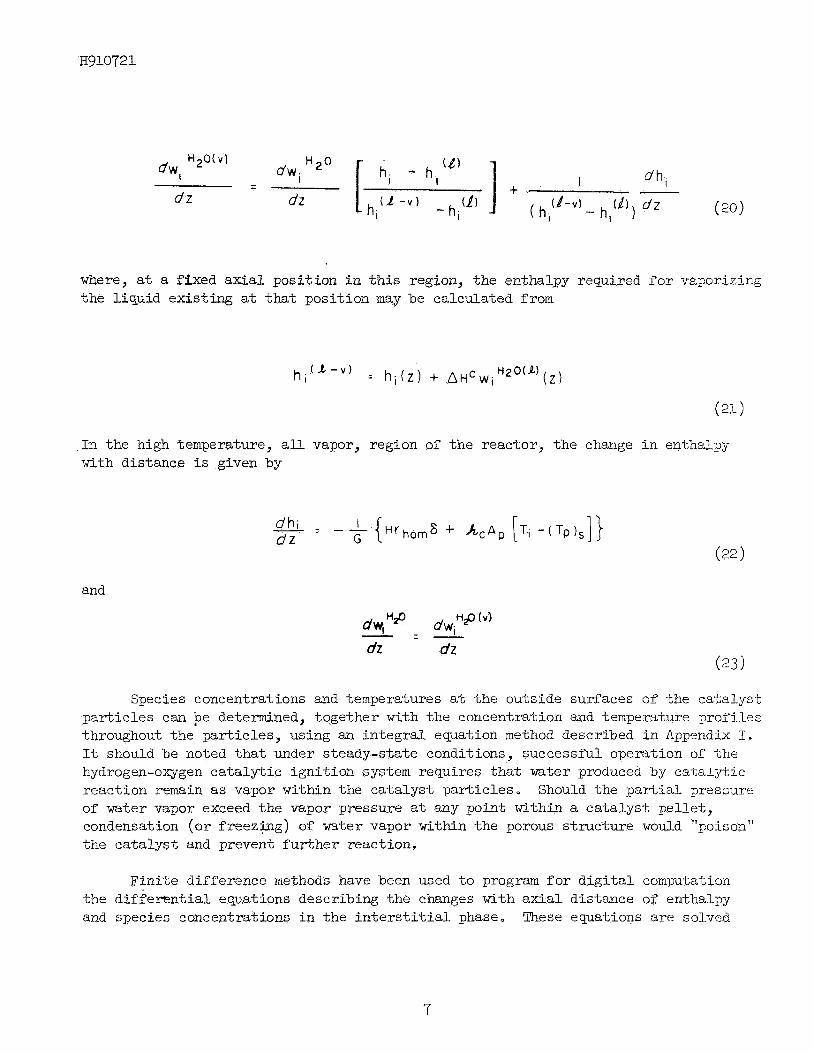
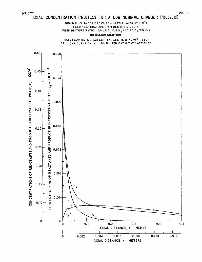
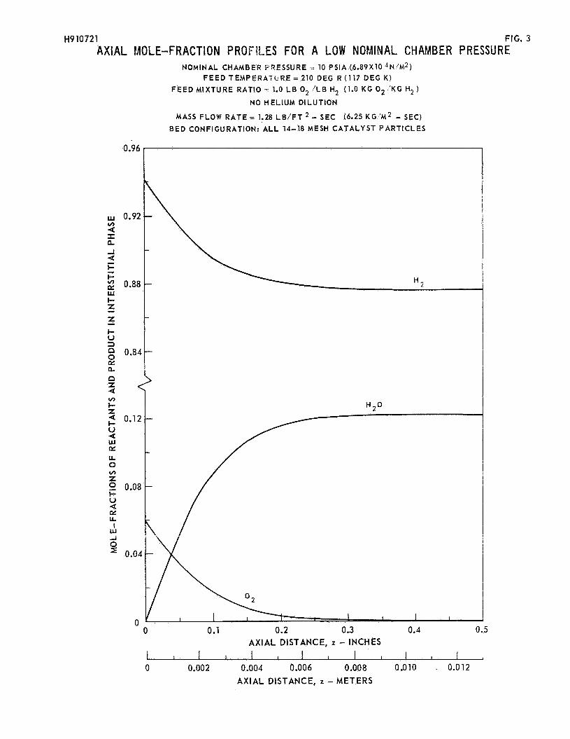
Sample calculations have been made using t h e computer program t o t e s t the effectiveness of the steady-state model as well as t o predict temperature and concentration prof i les i n typ ica l ca ta ly t ic ignit ion systems. Calculations have been made using a value of the catalyt ic reaction r a t e constant, a! , high enough t o insure t h a t the hydrogen-oxygen reaction was diffusion-controlled throughout the reactor. The resu l t s of one computer run are plotted i n Figs. 1 through 3 f o r a reactor packed with 14-18 mesh catalyst par t ic les aad f o r a nominal chamber pressure of 10 psia (6,89 x 10 temperature of 210 deg R (1-17 deg K ) , and no helium dilution. made f o r a reaction chamber 0.5 in. (0.013 m ) long and 0.87 in. (0.022 m ) i n diarneker, with a t o t a l propellant flow of 0.0053 lb/sec (0.0021c kg/sec); t h i s corresponds t o a mass flow ra te of 1.28 lb/ft2-sec (6.25 kg/m2-sec). rather high flow ra te i n t h i s low pressure system, the upstream chamber pressure was taken as 30 psia (2.07 x 10⁵ N/m2) ( i n subsequent calculations a t lower flow ra tes the upstrean chamber pressure w a s lowered correspondingly). The calculsted a x i a l temperature and chamber pressure prof i les f o r t h i s reference case are shown i n Fig. 1. l iquid and vapor) a r e shown i n Fig. 2 and the associated mole-fraction profiles are i l l u s t r a t ed in Fig. 3.
4 N/m*),a mixture r a t io of 1.0 lb 02/lb H2, an i n l e t The calculations were
I n order t o accommodate t h i s
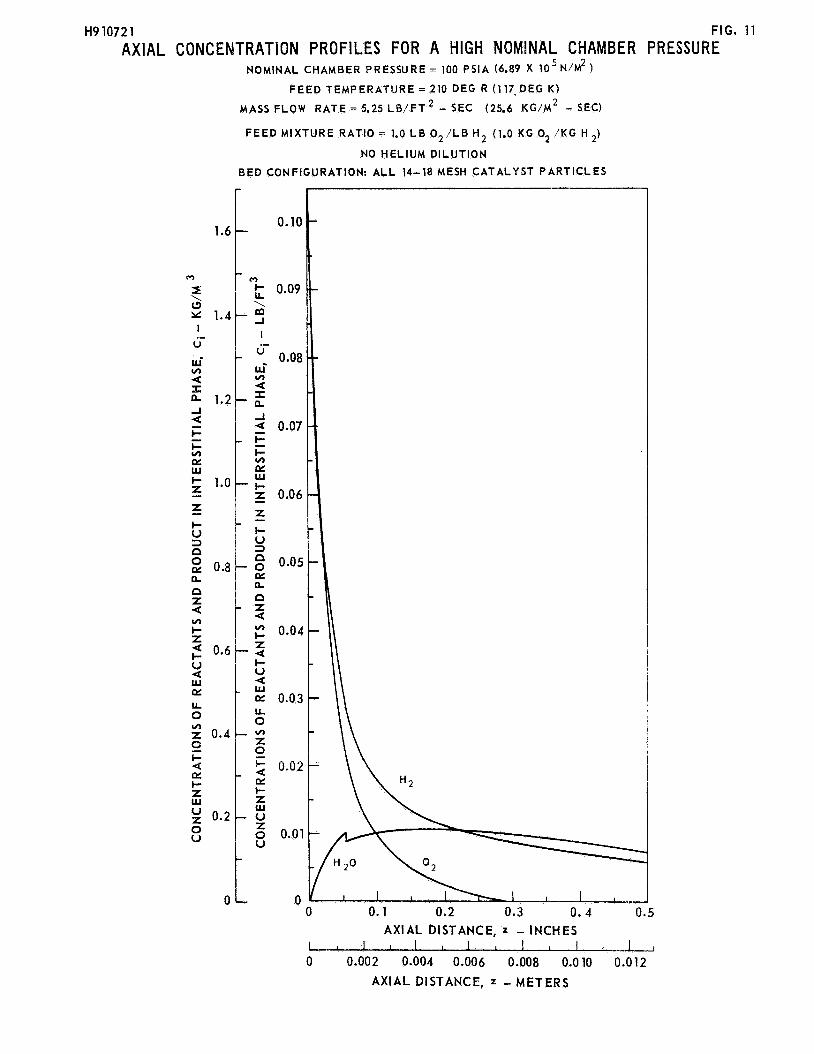
The ax ia l concentration prof i les f o r hydrogen, oxygen, and water ( s o l i d ,
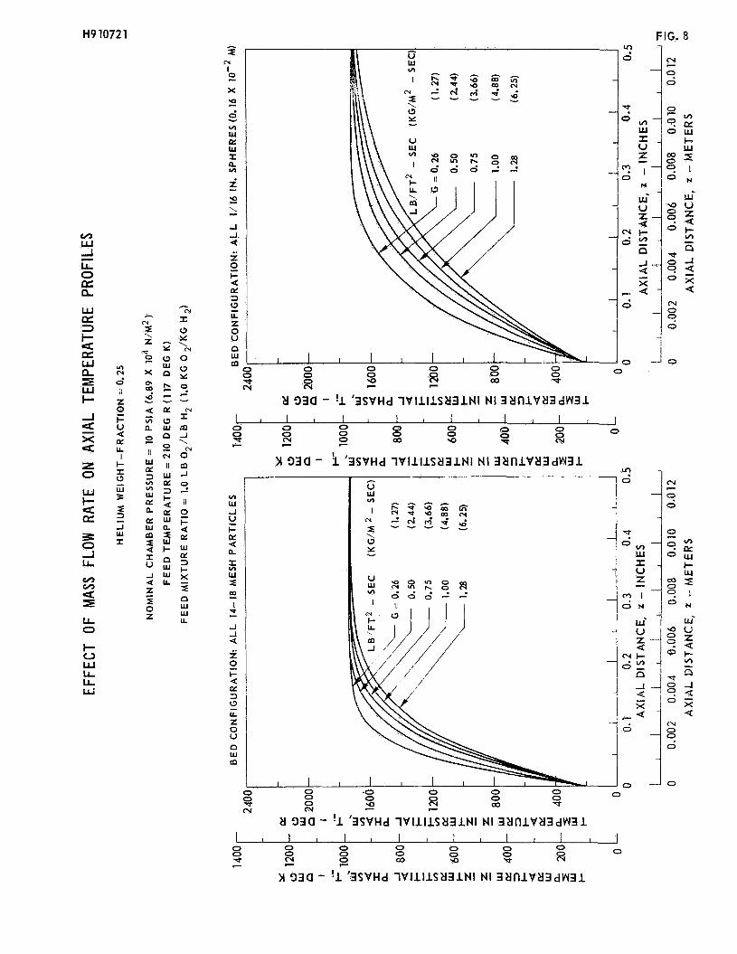
The e f fec t of feed temperature on the ax ia l temperature prof i le associated w i t h the reference case ci ted above i s depicted i n Fig. 11.
Fig. 4 -is the e f fec t of feed temperature f o r a reaction chamber packed with 1/16 i n . (0.16 x 10⁻² 31) diameter s reference case e noted tha t the temperature prof i les associated %ri,th
Also i l l u s t r a t ed i n
res; a l l other conditions were taken as those of the
3
H910721
the smaller (14-18) mesh par t ic les a re steeper because heat and mass t ransfer ra tes vary inversely with pa r t i c l e s ize .
The e f fec t of stoichiometry on temperature prof i les is i l l u s t r a t ed i n Fig, 5 f o r both the reference case and f o r the bed configuration consisting of 1/16 in. (0.16 x 10⁻² m ) spheres. concentmtion was fixed a t the same value used i n the reference case and mixture r a t io s above 1.0 were achieved by replacing the appropriate amount of hydrogen with helium. temperatures because helium has a lower heat capacity than hydrogen.
I n each of the curves i l l u s t r a t ed here the i n l e t oxygen
Under these conditions, the higher mixture ra t ios resu l t i n higher gas
The ef fec t of helium di lut ion on temperature dis t r ibut ions is shown i n Fig. 6 f o r the two bed configurations. Here the mixture r a t i o was fixed a t 1.0 and various amountsof diluent gas were added t o the i n l e t mixture. Here temperatures decrease with increasing helium concentration simply because there i s less oxygen t o react.
The e f fec ts of mass flow ra te on ax ia l temperature prof i les are i l l u s t r a t ed i n Figs. 7 through 9 f o r both bed configur5tions and f o r three different i n l e t helium concentrations. I n Fig. 7 the e f fec t of varying the mass flow ra te from 0.26 lb/ft2-sec (1.27 kg/m%ec) to 1.28 lb/ftZ-sec (6.25 kg/m2-sec) i s i l l u s t r a t ed f o r a system with no helium dilution. various mass f low rates i n Fig. 8 f o r an i n l e t helium weight-fraction of 0.25 and i n Fig. 9 f o r an i n l e t helium weight-fraction of 0.50.
Axial temperature prof i les are plotted f o r
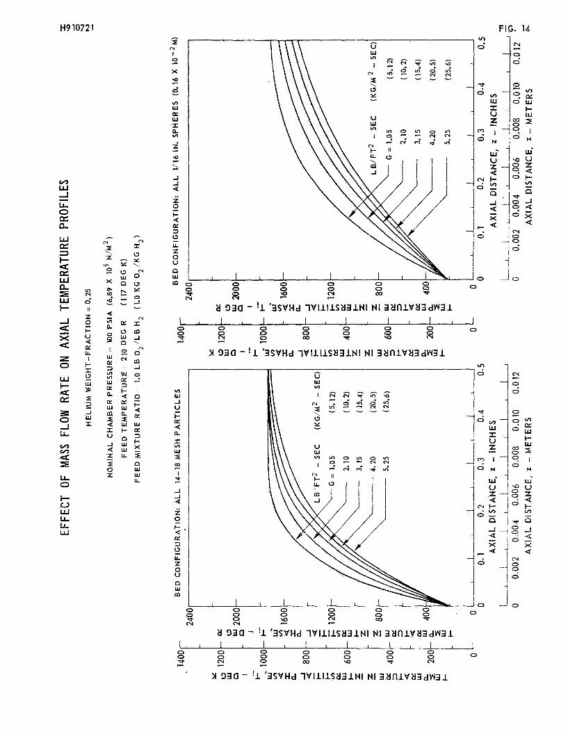
In order t o evaluate the effects of higher chamber pressure and higher m s s s f low rates on the steady-state behavior of these reactors, calculations were made f o r a reactor 0.43 in. (0.011 m ) i n diameter, with the t o t a l propellant flow remaking at 0.0053 lb/sec (0.0024 kg/sec); t h i s corresponds t o a mass flow ra te of 5.24 lb/ft2-sec (25.6 kg/m2-sec). 100 p i a (6.89 x 10⁵ N/m2) while the other reactor design and operating conditions were chosen as those of the reference case ci ted previously. The calculated ax ia l tenperature m-d chamber pressure prof i les f o r t h i s case a re shown i n Fig. 10. The ax ia l concentration prof i les f o r hydrogen, oxygen and water are shown i n Fig. 11 a d the associated mole-fraction prof i les are i l l u s t r a t ed i n Fig. 12.
The nominal chamber pressure was taken as
For +his higher ~ r e ~ s i r e reactcr, the e f f e c t s of mass flow ra t e on ax ia l temperature prof i les a re i l l u s t r a t ed f o r a reactor packed with 14-18 mesh pamicle; and for a reactor packed w i t h 1/16 in . (0.16 x 15. Calculations were made f o r a mixture r a t i o of 1.0 and f o r mass flow rates varying between 1.05 lb/ft2-sec (5.12 kg/m2-sec) and 5.25 lb/ft2-sec (25.6 kg/m*--snc). The resu l t s of these calculations a re plotted i n Fig. 13 f o r a system w i t 5 no heliwn dilution, in Fig. 14 f o r an i n l e t helium weight-fraction of 0.25, and i n Fig. l 5 €or an inlet - helium weight-fraction of 0.50.
m ) spheres i n Figs. 13 through
Definition of Rate-Controlling Processes
A s noted previously, prelimfi-ary indications (Ref. 13) are tha t , under steady- s t a t e conditions, diffusion of reactants from the free-gas phase t o the surface of the catalyst par t ic les may control the ra te of the hydrogen-oxygen reaction through- out the reactor. Although the calculated resu l t s described i n the preceding section were based on this assumption, fur ther validation i s required using detailed engine t e s t data. If the assumption is valid, it implies t h a t at steady-state, catalyst pa r t i c l e temperatures a t an axial position near the i n l e t of the reactor are con- siderably higher than the bulk f lu id temperature a t the same ax ia l position. is apparent t h a t t h i s same condition cannot ex i s t i n the early stages of t ransient operation i f the catalyst bed i s i n i t i a l l y a t a temperature close t o the i n l e t propellant temperature. by diffusion and reaction within the porous catalyst par t ic les . A t ransient model of a hydrogen-oxygen ca ta ly t ic ignit ion system should therefore consider both fil?i m d pore diffusion of heat and mass as w e l l as the chemical kinet ics of catalyt ic reaction of hydrogen and oxygen. I n addition, consideration should be given t o the effects on t ransient reactor behavior of the temporary reduction i n catalyst ac t iv i ty caused by capi l lary condensation o r freezing of water i n cold catalyst par t ic les .
It
In the l a t t e r case the reaction r a t e may w e l l be controlled
REFERENCES
1.
2 ,
3.
4.
5 .
6.
7.
8.
3.
10.
11.
12.
13 *
Roberts, R. W., H. L. Burge and M. Ladacki: Investigation of Catalytic Ignition of Oxygen/Hydrogen Systems. NASA CR-54657, December 1965.
Development of Hydrogen-Oxygen Catalysts. NASA CR-72118, July 1966.
Rodewald, N., G. Falkenstein, P. Herr, and E. Prono: Evaluation and Demonstra- tion of the Use of Cryogenic Propellants (02/H2) for Reaction Control Systems , Volume II--E%perimental Evaluations and Demonstration. NASA CR-72244, June 1966.
Kesten, A'. S.: tion.
Analytical Study of Catalytic Reactors for Hydrazine Decomposi- United Aircraft Research Laboratories Report F910461-12, May 1967.
Kesten, A. S.: Analytical Study of Catalytic Reactors for Hydrazine Decomposi- tion. - Part I: Steady-State Behavior of Hydrazine Reactors. Proceedings of the Hydrazine Monopropellant Technology Symposium, the Johns Hopkins University Applied Physics Laboratory, Silver Spring , Maryland , November 1967. Kesten, A. S. and T. W. Price: Analytical and Experimental Studies of the Transient Behavior of Catalytic Reactors for Hydrazine Decomposition. Pro- ceedings of the CPIA 10th Liquid Propulsion Symposium, Las Vegas, Nevada, November 1968.
Bird, R. B., W. E. Stewart, and E. N. Lightfoot: Transport Phenomena. John Wiley & Sons, Inc., New York, 1960.
Flouterghem, J. van and A. van Tiggelen: Bull. SOC. Chim. Belg., 64, 99 (1.955). - Kaskan, W. E.: 6th Combustion Symposium (Reinhold, New York, 1957), p. 134.
Sawjer, R. F.: The Homogeneous Gas Phase Kinetics of Reactions in the Hydmzine- Nitrogen Tetroxide Propellant System. Princeton University, Department cf Aero- space and j d e c ~ ~ ~ ~ c a l 5 r . G LAL,Lices .;; 2epoI-t BO. 751, 1365.
Miller, F. W. and H. A. Deans: An Experimental Study of Nonisothermal Effective- ness Factors in a Porous Catalyst. AIChE Journal, V o l . 13, 1967, pp. 45-51.
Mayno, J. A, and J. M. Smith: Catalytic Oxidation of Hydrogen-Intrapellet Heat and Mass Transfer. AIChE Journal, Vol. 12, 1966, pp. 845-854.
Investigation of Thrustors for Cryogenic Reaction Control Systems. TRW Systems Twelfth Monthly Progress Report, NASA Contract NAS 3-11227, June 1969.
RFPERERCES (cont 'a)
14. Prater, D. C.: The Temperature Produced by Heat of Reaction in the Interior of Porous Particles. Chemical Engineering Science, Vol. 8, 1958, pp. 284-286.
150 Kesten, A. S.: An Integral Equation Method for Evaluating the Effects of Film and Pore Diffusion of Heat and Mass on Reaction Rates in Porous Catalyst Particles. AIChE Journal, Vol. 15, 1969, pp. l28-131.
H910721
LIST OF SYMBOLS
a Radius of spherical catalyst par t ic le , f t (m)
Total external surface of catalyst par t ic le per unit volume of bed, ft-’(m-’)
Reactant concentration i n i n t e r s t i t i a l f lu id , l b / f t 3 (kg/m3)
AP
‘i
P C
c f
Di
DP
G
H
ET P
Reactant concentration i n gas phase within the porous catalyst par t ic le , Ib / f t3 (kg/m3)
Specific heat of f l u id i n the i n t e r s t i t i a l phase, Btu/lb-deg R (Cal/kg-deg K )
Average specif ic heat of f l u id i n the i n t e r s t i t i a l phase, Btu/lb-deg R (Cal/kg-deg K )
Diffusion coefficient of reactant gas i n the i n t e r s t i t i a l phase, f t2/sec (m2/s ec )
Diffusion coefficient of reactant gas i n the porous par t ic le , f t2/sec ( m2/se c )
Mass flow rate , lb/ft2-sec (kg/m2-sec)
Enthalpy, Btu/lb (Cal/kg )
Enthalpy a t the Ice/Ice-Liquid interface, Btu/lb (Cal/kg )
Enthalpy a t the Ice-Liquid/Liquid interface, Btu/lb (Cal/kg )
Enthalpy a t the Liquid/Liquid-Vapor interface, Btu/lb (Cal/kg )
Enthalpy a t the Liquid-Vapor/Vapor interface, Btu/lb (Cal/kg )
Heat t ransfer coefficient, Btu/ft2-sec-deg R (Cal/m2-sec-deg K )
Heat of reaction, Btu/lb (Cal/kg)
Heat of condensation, Btu/lb (Cal/kg)
Heat of fusion, Btu/lb (Cal/kg)
-Mass t ransfer Coefficient, f t / sec (m/sec)
Thermal conductivity of the porous catalyst par t ic le , Btu/ft-see-deg R (Cal/m-sec-deg K )
H910721
M
M
Molecular weight, lb/lb mole (kg/kg mole )
Average molecular weight, lb/ lb mole (kg/kg mole) -
P Chamber pressure, psia (N/m2)
rhet Rate of (heterogeneous) chemical reaction on the catalyst surfaces, lb/ft3-sec (kg/m3-sec )
Rate of (homogeneous ) chemical reaction i n the i n t e r s t i t i a l phase, lb/ft3-sec (kg/m3-sec )
Temperature, deg R (deg K )
'horn
T
wi Weight f rac t ion of reactant i n i n t e r s t i t i a l phase
X Radial distance from the spherical catalyst par t ic le , f t ( m )
Z Axial distance, f t ( m )
CY Catalytic reaction ra te constant
6 In te rpar t ie le void fract ion
I-1
Pi
Viscosity of i n t e r s t i t i a l f luid, lb/ft-see (kg/m-see )
Density of i n t e r s t i t i a l f lu id , l b / f t3 (kg/m3)
Su-b s c r i p t s
F Refers t o feed
i Refers t o i n t e r s t i t i a l phase
P Refers t o gas within the porous catalyst par t ic le
s Refers t o surface of catalyst par t ic le
Superscripts
H20(s) Refers t o water i n the sol id phase
H20(J) . Refers t o water i n the l iquid phase
%O(v) Refers t o water i n the vapor phase
J
( v > Refers t o vapor phase
R2fers t o chemical spycies (e.G. €I2, 02, ~ ~ 0 , He)
H910721
Generalization t o Multireactant Systems of t he Integral Method used t o Evaluate t h e E f e c t s of Heat and Mass Diffusion
on Reaction Rates i n Porous Catalyst Par t ic les
The system under consideration i s a spherical porous ca ta lys t p e l l e t which i s surroundea by a stagnant f i lm of f lu id . Reactant molecules must diffuse through t h i s f i lm and in to the in t e r s t i ce s of t he porous par t ic le before reacting on the ca t a ly t i c surfaces. I n describing the diffusion of mass within a porous pel le t , it is assumed t h a t Fick’s l a w applies and t h a t changes i n the mass density of f l u i d within the par t ic le a re negligible r e l a t ive t o changes i n concentrations of the reacting species. Fourier’s l a w is used t o describe heat conduction within the ca ta lys t pe l le t . Pressure changes within the par t ic le resul t ing from non-equimolar diffusion are neglected as i s heat transported by pore diffusion of mass. Heat and mass transfer coeff ic ients are used t o describe f i lm diffusion of heat and mass. Assuming constant diffusion coeff ic ients , Dp, and thermal conductivities, Kp, within the porous s t ructure , the equations describing heat and mass t ransfer of a s ingle reactant i n a ca ta lys t pa r t i c l e may be writ ten as
D p v 2 C p - ‘het = 0
K ~ V ~ T~ - H rhet = 0
vhere the concentration, c and r a t e of reaction, set, a re expressed i n mass uni ts . The boundary conditions which consider diffusion of heat and mass through a f i l m swromdtng a spherical part,i.cl e are
P’
Using Eqs. (1-1) and (I-2), Prater (Ref. 14) has pointed out that temperature and concentration are related quite simply by
The use of this relationship enables the reaction rate, %et, to be written, for given surface conditions, as a function of concentration alone instead of concen- tration and temperature. It is only necessary, then, to solve Eq. (1-1) with net = %et (ep), subject to boundary conditions (1-3) and (1-4). The solution is derived in Refs. 5 and 1 5 as an implicit integral equation given by
(1-6)
Equation (1-6) can be solved numerically to determine the concentration at any point in a porous particle in terms of ci, the concentration in the bulk fluid. of the dependence of the reaction rate, qet, on particle surface temperature, (Tp)s, and reactant concentration, ( c ~ ) ~ , it is necessary to solve Eq. (1-6) simultaneously with Eqs. (1-3) and (1-4) to determine the concentration profile within the particle. Eanerical methods have been developed to accomplish this and these have been prograrxxed for digital computation.
Because
\
2escription of multiple reaction systems. Consider a reacting system where A n important generalization of the integral method presented above involves a
a A + b B + . . I -+ t T + . . . . Tt 1.5 aypai-eiit t‘nat Lhe rete of the reaction can be cxpresset! in terns of m y of the reactants or products; however, the rate may be a function of the concentration of any or all of those species. porous catalyst particle must then be determined by simultaneous solution of
The concentration profile of any species within a
and Kp V 2 T p - H A A 'bet (cp A B , c p , . . . , cp T , . . . 1 T p ) = 0
(1-29 j
where the diffusion coeff ic ients and thermal conductivities a re again taken as con- s t an t , and the heat of reaction, H , i s expressed i n terms of heat absorbed per un i t mass of species A. mass and heat a re
A
The boundary conditions 'which consider f i l m diffusion of
a . b . e b
. a . a .
(1-11 )
(1-12)
(1-1; )
(1-14 j
As noted previously, Prater ( R e f . 14) has pointed out, th3.t temperature and reactant concentration a re related by Eq. (5 ) , where the concentrations, c and ( c ~ ) ~ , re fer P
13
H910721
in this case to species A. The same procedure used in Ref. 14 can be employed to relate all reactant and product concentrations at any point within the porous catalyst particle to the concentration of reactant A at the same point. Thus
.
*
(1-15)
(1-16)
Surface concentrations, (c~)~, of all reactants and products can be written in terms of the surface concentration of reactant A and the known concentrations in the bulk fluid by combining Eqs. (1-11) and (1-12) and then Eqs. (1-11) and (1-13) to get
. . .
(1-18)
With particle temperature and reactant and product concentration distributions all expressed in terms of the concentration profile of one reactant, the reaction rate at any point in the particle, rhet, can be expressed, for given surface conditions, as a function of the local concentration of one reactant only. Thus, as in the case of a single reactant, integral Eq. (1-6) (with concentrations referring to reactant A) nay be solved simultaneously with boundary conditions (1-11) and (1-14) to fully rletermine the concentration and temperature profiles within the porous catalyst particle.
Mai l Stop 500-209 NASA Lewis Research Center Cleveland, Ohio, 44135 Pro jec t Manager - Paul N . Herr
Chief, L i q u i d Propuls ion Technology, RPL O f f i c e o f Advanced Research and Technology NASA Headquarters Washington, D.C., 20546
5
4
NASA S c i e n t i f i c & Technical In format ion F a c i l i t y 25 P. 0. Box 33 College Park, Maryland, 20740
D i rec to r , Launch Vehi c l es and Propul s i on, SV 1 O f f i c e o f Space Science and App l ica t ions NASA Headquarters, Washi ngton, D .C., 20546
D i rec tor , Advanced Manned Missions, MT O f f i c e o f Manned Space F l i g h t NASA Headquarters, Washington, D .C., 20546
Mission Analysis D i v i s i o n NASA Ames Research Center M o f f e t t F ie ld , Ca l i f o rn ia , 24035
Ames Research Center M o f f e t t F ie ld , Ca l i f o rn ia , 94035 A t t n : Technical L i b r a r i a n
Goddard Space F l i g h t Center Greenbelt, Maryland, 20771 A t t n : Technical L i b r a r i a n
J e t Propulsion Laboratory Cal i f o r n i a l n s t i t u t e o f Technology 4800 Oak Grove Dr ive Pasadena, Cal i forni a, 91 103 At tn : Technical L i b r a r i a n
Langley Research Center Langley S ta t i on Hampton, V i rg in ia , 23365 A t t n : Techni cal L i b r a r i a n
2
2
2
No. o f Copies
Lewis Research Center 21000 Brookpark Road Cleveland, Ohio, 44135 A t t n : Technical L i b r a r i a n
Marshall Space F l i g h t Center Huntsvi 1 1 e, A1 abama, 3581 2 A t tn : Technical L i b r a r i a n
John F. Kennedy Space Center, NASA Cocoa Beach, F lo r ida , 32931 A t t n : Technical L i b r a r i a n
Aeronautical Systems D i v i s i o n A i r Force Systems Command Wright-Patterson A i r Force Base Dayton, Ohio, 45433 A t t n : Techn i ca 1 L i bra r i an
A i r Force M i s s i l e Development Center Holloman A i r Force Base, New Mexico, 88330 A t t n : Technical L i b r a r i a n
Arnold Engi neeri ng Development Center Arnold A i r Force Sta t ion Tu1 1 ahoma , Tennessee, 37389 A t t n : Technical L i b r a r i a n
Bureau of Naval Weapons Department’ o f t h e Navy Washington, D . C . , 20360 At tn : Technical L i b r a r i a n
Defense Documentation Center Headquarters Cameron Stat ion, Bu i l d ing 5 5010 Duke Street Alexandria, V i rg in ia , 22314 k t t n : T i S f A At tn : Technical L i b r a r i a n
NASA Manned Spacecraft Center Houston, Texas, 77058 A t t n : Technical L i b r a r i a n
Headquarters , U .S. A i r Force Washington, D.C., 20330 A t tn : Technical L i b r a r i a n
P i cat i nny Arsenal Dover, New Jersey, 07801 A t t n : Technical L i b r a r i a n
2
1
1
61
3
No. o f Copies
A i r Force Rocket Propuls ion Laboratory Research and Technology D i v i s i o n A i r Force Systems C m a n d Edwards, Cal i f o r n i a, 93523 A t t n : Technical L i b r a r i a n
U.S. Army M i s s i l e C m a n d Redstone Arsenal Huntsvi 1 1 e, A1 abama, 35809 A t t n : Technical L i b r a r i a n
Naval Weapons Center China Lake, Ca l i f o rn ia , 93557 A t t n : Tec hn i ca 1 L i b ra r i a n
Chem i ca 1 P ropul s i on I nformat ion Agency Applied Physics Laboratory 8621 Georgia Avenue S i l v e r Spring, Maryland, 20910 A t tn : Technical L i b r a r i a n
Aerojet-General Corporation P. 0. Box1947 Technical L ib ra ry , Bldg. 2015, Dept. 2410 Sacramento, C a l i f o r n i a , 95809 A t t n : Technical L i b r a r i a n
Aeronautronic Phi l c o Corporation Ford Road Newport Beach, Cal i fo rn ia , 92663 A t t n : Technical L i b r a r i a n
Aerospace Corpora t i on 2400 East E l Segundo Boulevard P. 0. Box 95085 Los Angel es , Cal i f o r n i a, 90045 A t t n : Technical L i b r a r i a n
Beech A i r c r a f t Corporat i on Bou 1 der D i v i s i on Box 631 Boul der, Colorado, 80302 A t t n : Technical L i b r a r i a n
1
1
1
2
2
1
1
1
62
4
B e l l Aerosystems Company P . 0. Box 1 Buf fa lo , New York, 14240 A t t n : Technical L i b r a r i a n
Frank Herud
Bendix Systems D i v i s Bend i x Corpo r a t i on 3300 Plymouth Road Ann Arbor, Michigan, A t tn : Technical L i b
on
481 05 a r i a n
Boeing Company P. 0. Box 3707 Seat t le , Washington, 98124 A t t n : Technical L i b r a r i a n
M i s s i l e D iv i s ion Chrys 1 e r Corporation P. 0. Box 2628 Oetroi t , Michigan, 48231 A t tn : Technical L i b r a r i a n
W r i ght Aeronaut i ca l D i v i s i on Curt iss-Wright Corporation Wood-Ri dge, New Jersey, 07075 A t t n : Technical L i b r a r i a n
M i s s i l e and Space Systems D i v i s i o n Douglas A i r c r a f t Company, lnc. 3000 Ocean Park Boulevard Santa Monica, Ca l i f o rn ia , 90406 A t tn : Technical L i b r a r i a n
A i r c r a f t M iss i l es D iv i s ion F a i r c h i l d H i l l e r Corporation Hagers town, Mary1 and, 21 740 A t t n : Technical L i b r a r i a n
Genera 1 Dynam i cs/As t ronau t i cs L ib ra ry and informat ion Services (128-00) P. 0. Box 1128 San Diego, Ca l i f o rn ia , 92112 A t tn : Technical L i b r a r i a n
No. o f Copies
1
1
1
1
1
No. o f Copies M i s s i l e and Space Systems Center General E l e c t r i c Company Val 1 ey Forge Space Technol ogy Center P. 0. Box 855 Phi ladelphia, Pennsylvania A t tn : Technical L i b r a r i a n
Advanced Engi ne and Technol ogy Dep t . General E l e c t r i c Company Cinc innat i Ohio, 45215 A t tn : Technical L i b r a r i a n
Grumman A i r c r a f t Engineering Corp. Bethpage, Long Is land New York, 11714 A t t n : Technical L i b r a r i a n
Ling-Temco-Vought Corporation Astronaut ics P. 0. Box 5907 Dal las , Texas, 75222 A t tn : Technical L i b r a r i a n
Lockheed M iss i l es and Space Company A t t n : Technical in format ion Center P. 0. Box 504 Sunnyvale, Ca l i f o rn ia , 94088 A t tn : Technical L i b r a r i a n
Lockheed P ropu 1 s i on Company P . 0. Box 1 1 1 Redlands, Cal i f o r n i a , 92374 A t t n : Technical L i b r a r i a n
The Marquardt Corporation 16555 Saticoy St ree t Van Nuys, Ca l i fo rn ia , 91409 A t t n : Technical L i b r a r i a n
c1 I f f Coult?ert
Denver D iv i s ion Mart in-Mariet ta Corporation P. 0. Box 179 Denver, Colorado, 80201 A t tn : Technical L i b r a r i a n
1
1
1
1
1
64
6
No. of Copies
McDonnel 1 A i r c r a f t Corporation P. 0. Box 516 Municipal A i r p o r t S t . Louis, Missouri, 63166 A t t n : Technical L i b r a r i a n
Space and Informat ion Systems D i v i s i o n North American Aviat ion, Inc. 1221 4 Lakewood Boul w a r d Downey , Ca 1 i f o r n i a, 90241 A t t n : Technical L i b r a r i a n
Rocketdyne (L ib ra ry 586-306) North American Aviat ion, Inc. 6633 Canoga Avenue Canoga Park, Cal i forn ia , 91304 A t t n : Technical L i b r a r i a n
Northrop Space Laborator ies 3401 West Broadway Hawthorne, Ca l i f o rn ia , 90250 A t t n : Technical L i b r a r i a n
Republ i c Av ia t i on Corporation Farrningdale Long Is land, New York, 11735 A t t n : Technical L i b r a r i a n
Space General Corporation 9200 East F1 a i r Avenue El Monte, Cal i f o r n i a , 91734 A t t n : Technical L i b r a r i a n
TRW Systems Group TRW i ncorporated One Space Park Redondo Beach, Ca l i f o rn ia , 90278 A t t n : Technical L i b r a r i a n
Don Lee
TAPCO D i v i s i o n TRW , I ncorporated 23555 Euc l i d Avenue Cleveland, Ohio, 441 17 A t t n : Technical L i b r a r i a n
Thiokol Chemical Corporation H u n t s v i l l e D i v i s i o n Huntsvi 1 l e , Alabama, 35800 A t t n ; Techni cal L i b r a r i an
1
1
7
No. o f Copies United Technology Center 587 Methi Ida Avenue P. 0. Box 358 Sunnyvale, Cal i f o r n i a , 94088 A t t n : Technical L i b r a r i a n
Aerospace Operations Walter Kidde and Company, Inc. 567 Main Street B e l l e v i l l e , New Jersey, 07109 A t t n : Technical L i b r a r i a n
A i r Force Systems D i v i s i o n A i r Force U n i t Post O f f i c e Los Angeles, Ca l i f o rn ia , 90045 A t t n : Technical L i b r a r i a n
F1 o r i da Research and Development P r a t t C Whi tney A i r c r a f t United A i r c r a f t Corporation P. 0. Box 2691 West Palm Beach, F lo r i da , 33402 A t tn : Technical L i b r a r i a n
G. D. Lewis
Rocket Research Corporation York Center Redmond, Washington, 98052 A t t n : Technical L i b r a r i a n
1
1
1
6 1
1
66
H9 1072 1 FIG. 1
W a
VlSd - d '32lnSS32ld 2l38WVH3
0
L - u 0 - J
,W/N,OL - d '3tlnSS32id 2l39WVH3 ._ .
\
2l 33a - '1 '3SVHd l V l l l l S 2 l 3 1 N I NI 32lnlV2l3dW31 I I 1 I I I I I --LA
0 0 0 0 0 Y)
0 0 'd (v
0 0 0 0 0 0 cy E! m o-.
N _ I 0 1 % $
I
.lo
u) CY w t- w 2
I N
W' U z 4 t- u)
ii .J U X U -
)I 33a - '1 '3SVHd l V I l I l S 2 l 3 1 N l NI 32lnlVa3dW31