Page 1
Study of stair-climbing assistive mechanisms for the disabled
Murray John LAWN
Dissertation submitted to the faculty of Mechanical Systems Engineering For the Degree of Doctor of Philosophy
Graduate School of Marine Science and Engineering
Nagasaki University, Nagasaki City, Japan
December 2002
Page 2
i
Table of Contents 1 Introduction ..................................................................................................................... 1
1.1 Why stairs?................................................................................................................. 1
1.2 Stairs - are they safe?.................................................................................................. 3
1.3 Wheeled mobility ....................................................................................................... 4
1.4 Wheels and stairs........................................................................................................ 5
1.4.1 Motive force, curb height and wheel diameter.................................................. 6
1.5 Requirements for stair-climbing mobility .................................................................. 9
1.6 Common stair-climbing techniques and assistive devices ....................................... 11
1.6.1 Assistant based curb, slope and stair negotiation techniques........................ 11
1.6.2 Common stair-climbing and van entry assistive devices .............................. 13
1.7 Stairs - discussion..................................................................................................... 15
1.8 Thesis outline ........................................................................................................... 16
2 Recent advances in mobility assistive devices for stairs or curbs ............................... 18
2.1 Curb assistive mechanisms for wheelchairs............................................................. 18
2.2 Curb capable powered wheelchairs and mobility scooters ...................................... 19
2.3 Tracked based stair-climbers.................................................................................... 21
2.4 Lightweight wheelchair stair-climbing attachments ................................................ 23
2.5 Wheel cluster based stair-climbers........................................................................... 25
2.6 COG modification wheel cluster based stair-climber .............................................. 27
2.7 Dual wheel cluster based stair-climber .................................................................... 29
2.8 Miscellaneous stair-assist and van entry mechanisms ............................................. 30
2.9 Recent advances in mobility assistive devices for stairs or curbs, summary and
discussion ................................................................................................................. 31
3 Proposed high step and stair-climbing mechanism........................................................ 35
3.1 Introduction .............................................................................................................. 35
3.2 Proposed mechanism................................................................................................ 35
3.3 Modeling process ..................................................................................................... 36
3.3.1 Numerical model ......................................................................................... 37
Page 3
ii
3.3.2 Linear actuator power calculations ............................................................. 40
3.3.3 High step stair-climbing mechanism stability margins ............................... 45
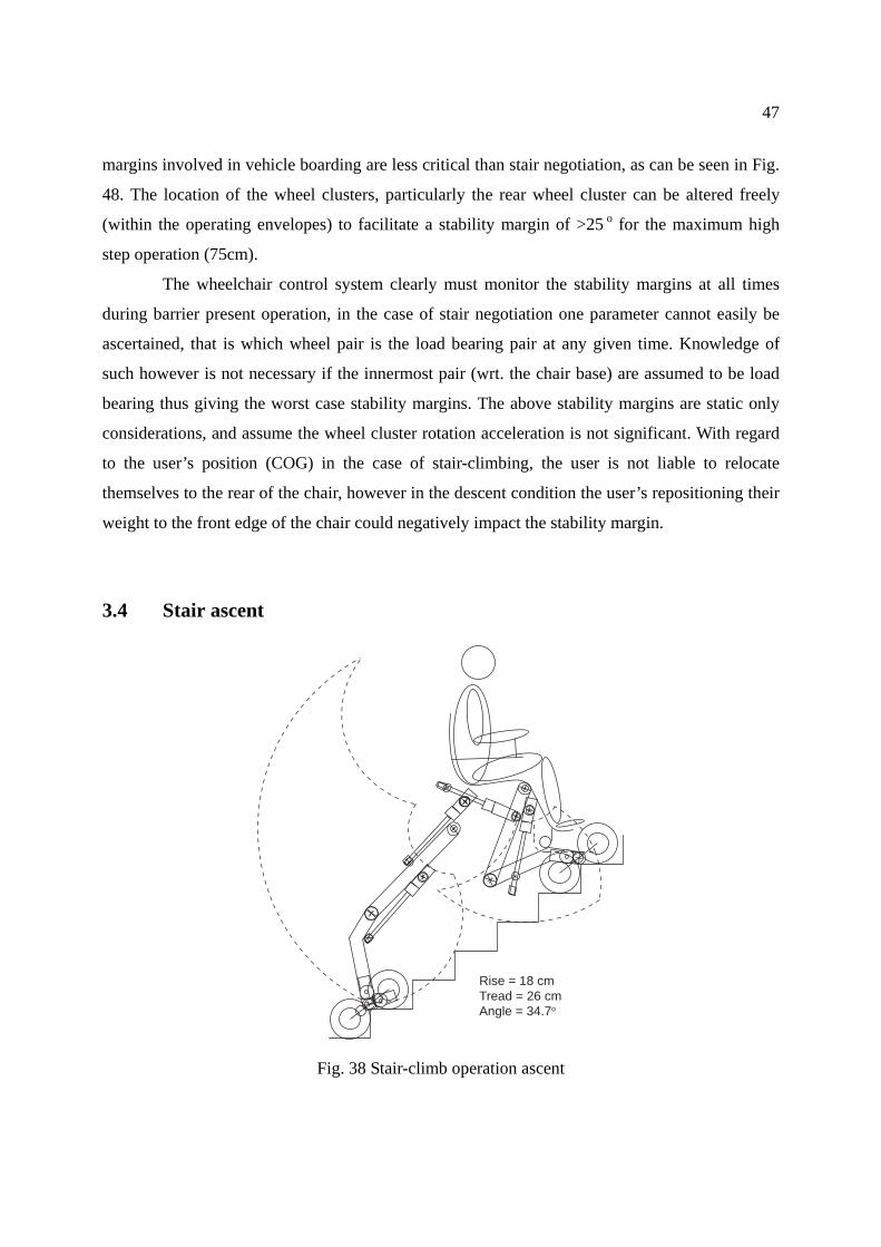
3.4 Stair ascent ............................................................................................................... 47
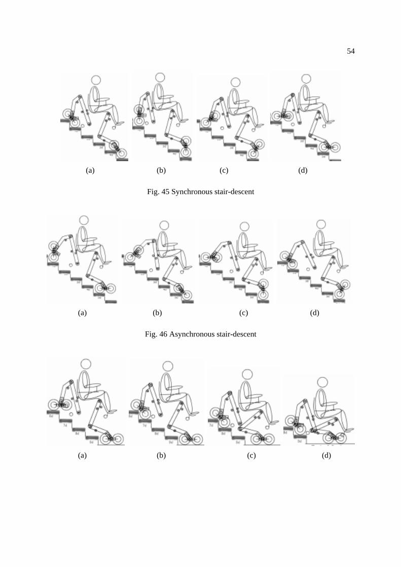
3.5 Stair descent ............................................................................................................. 51
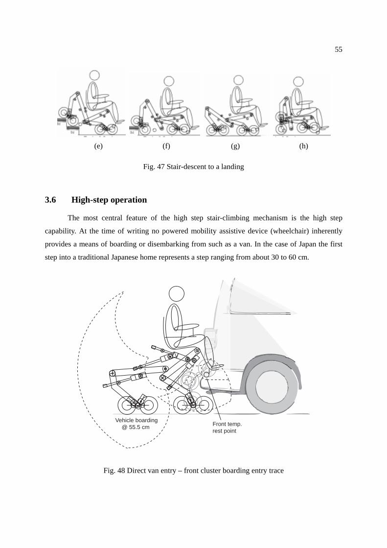
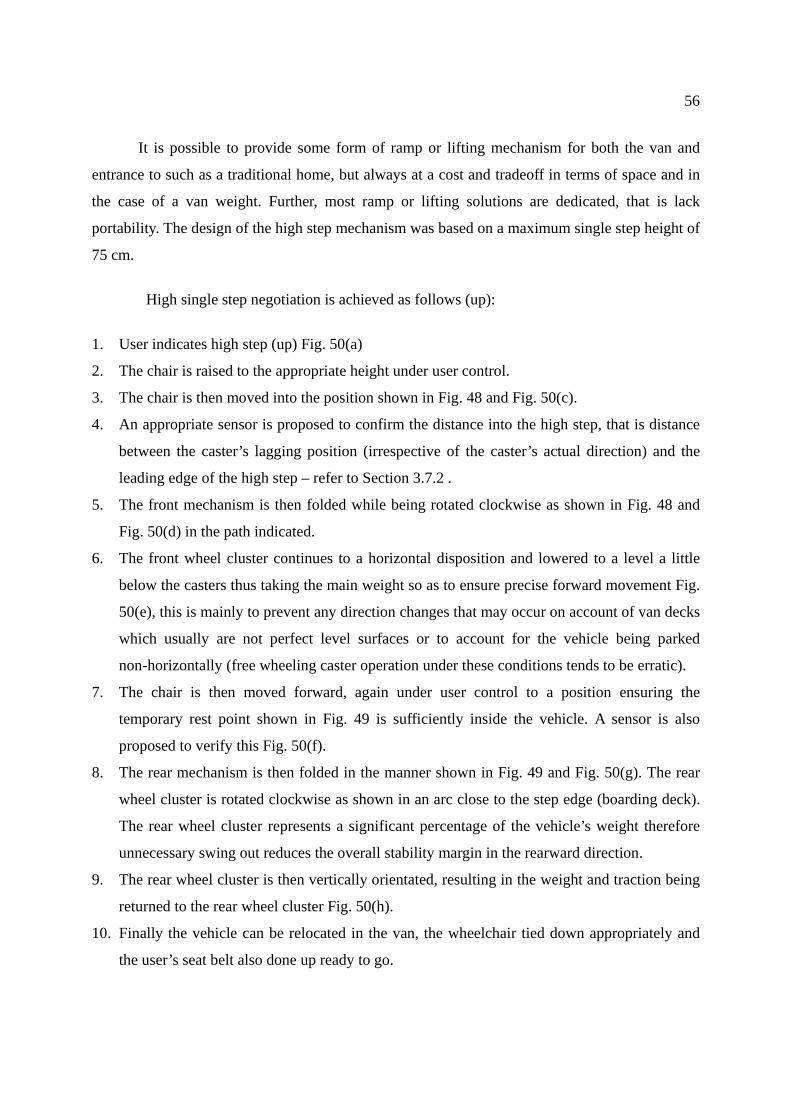
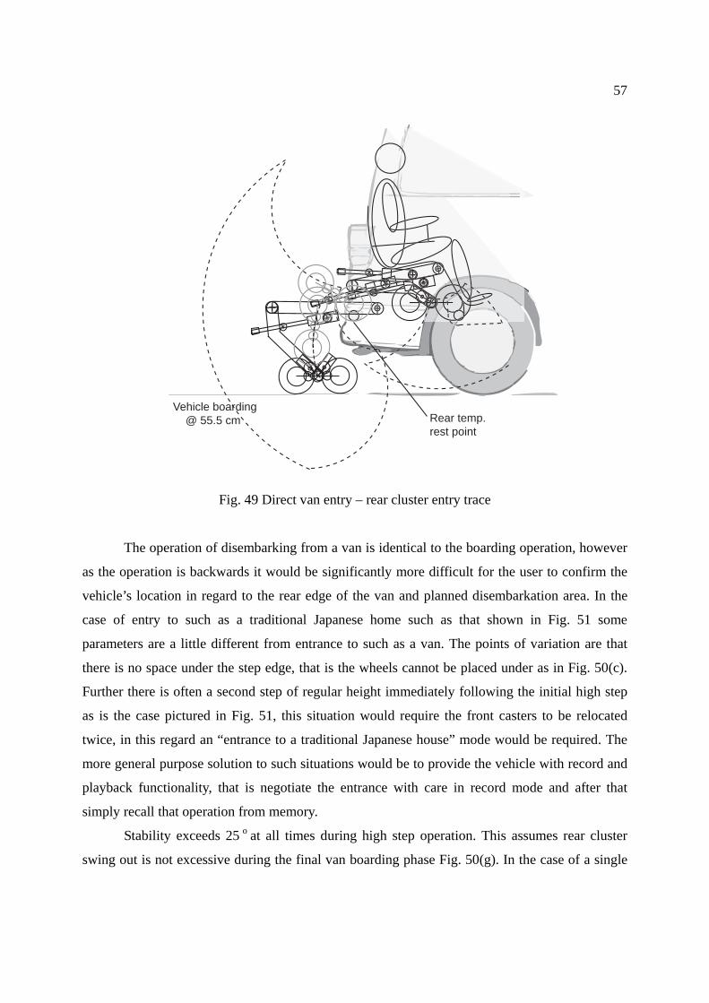
3.6 High-step operation .................................................................................................. 55
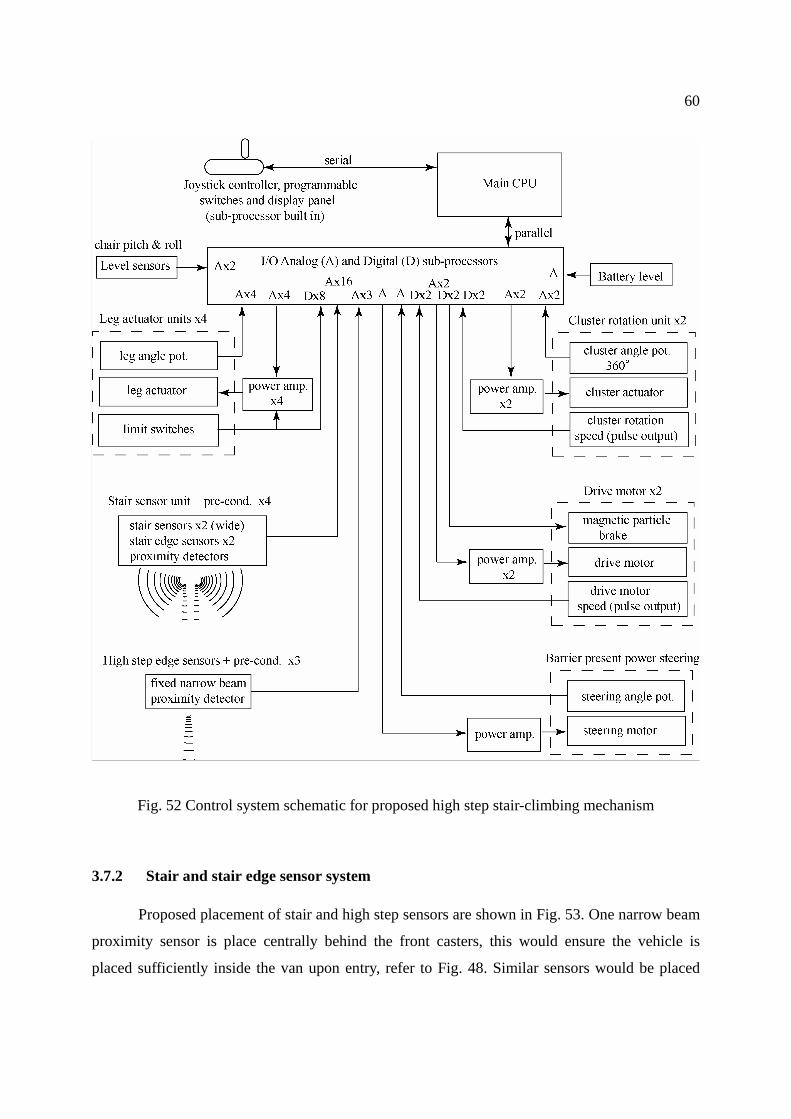
3.7 Proposed control system........................................................................................... 59
3.7.1 Control system............................................................................................. 59
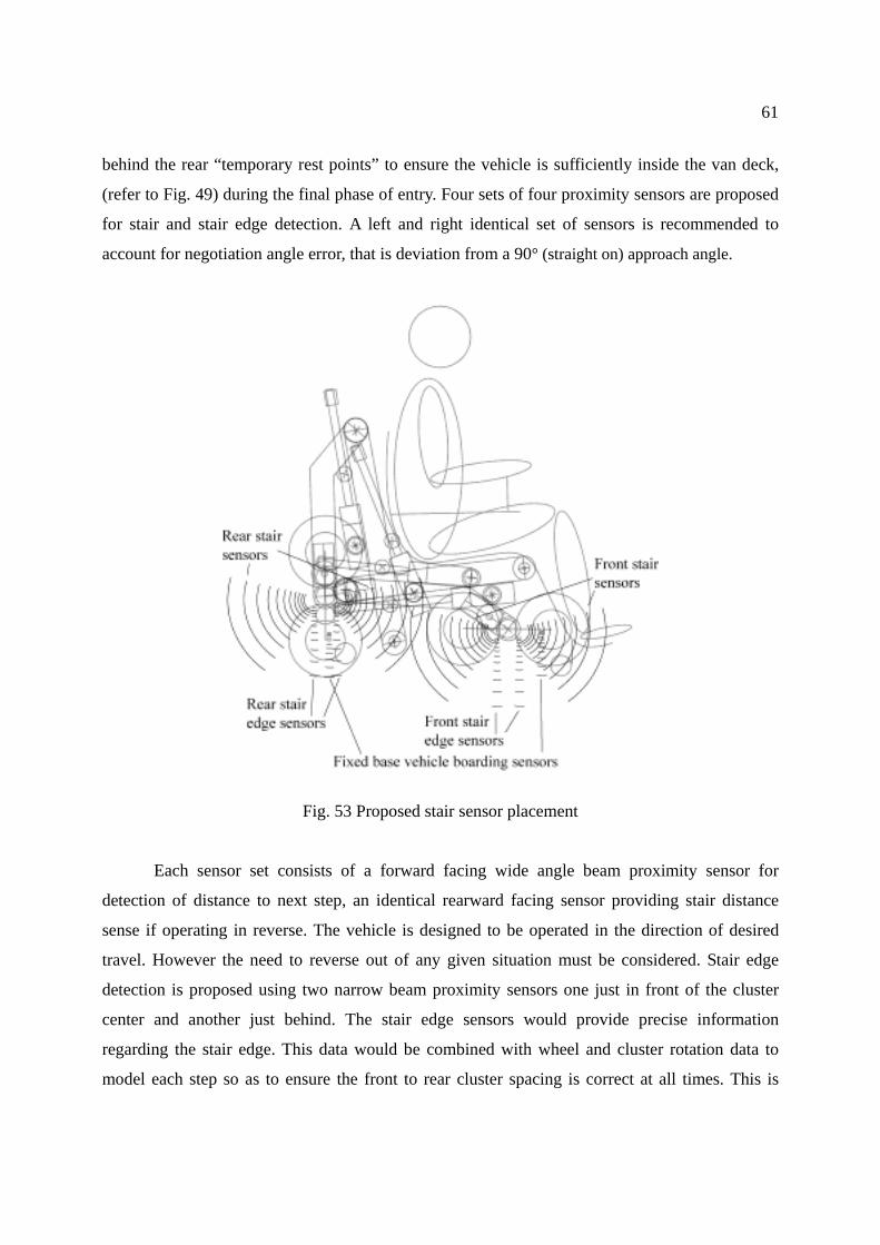
3.7.2 Stair and stair edge sensor system............................................................... 60
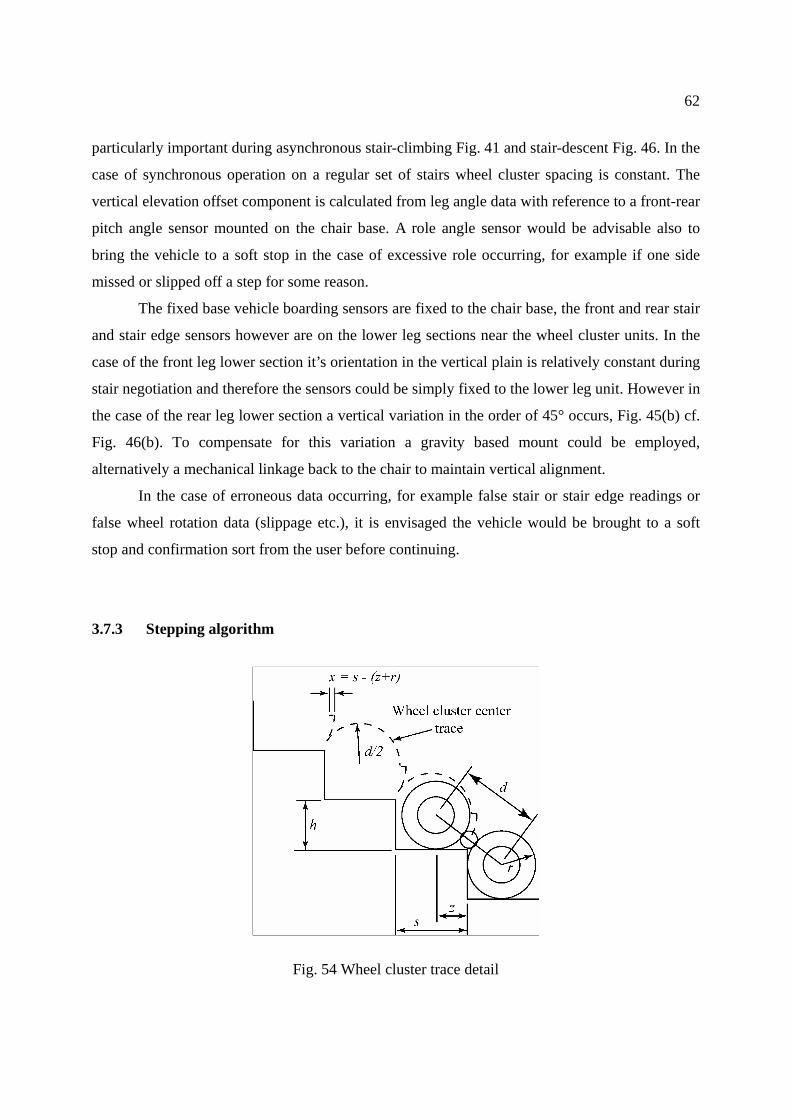
3.7.3 Stepping algorithm ...................................................................................... 62
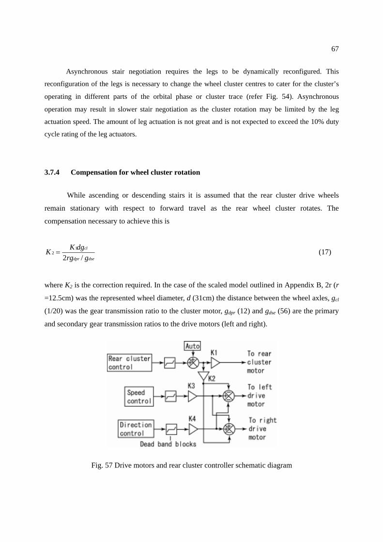
3.7.4 Compensation for wheel cluster rotation .................................................... 67
3.8 High step and stair climbing mechanism - discussion ............................................... 68
4 Proposed track based stair-climbing mechanism........................................................... 72
4.1 Introduction - tracked operation............................................................................... 72
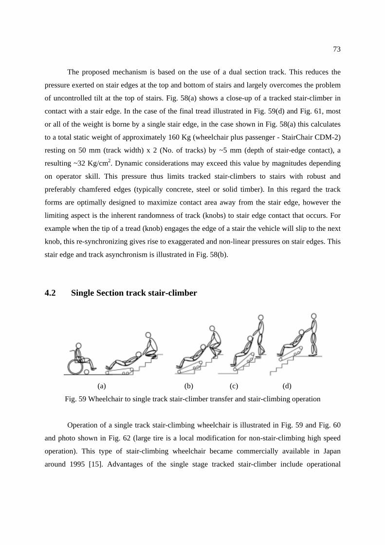
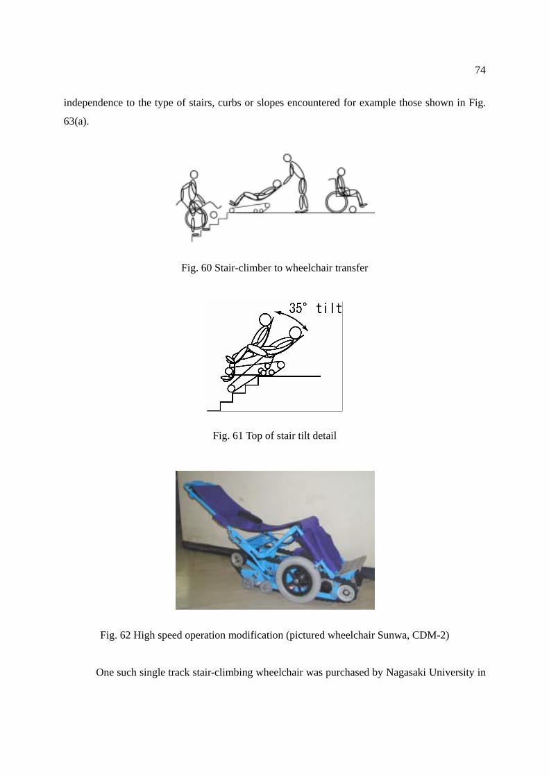
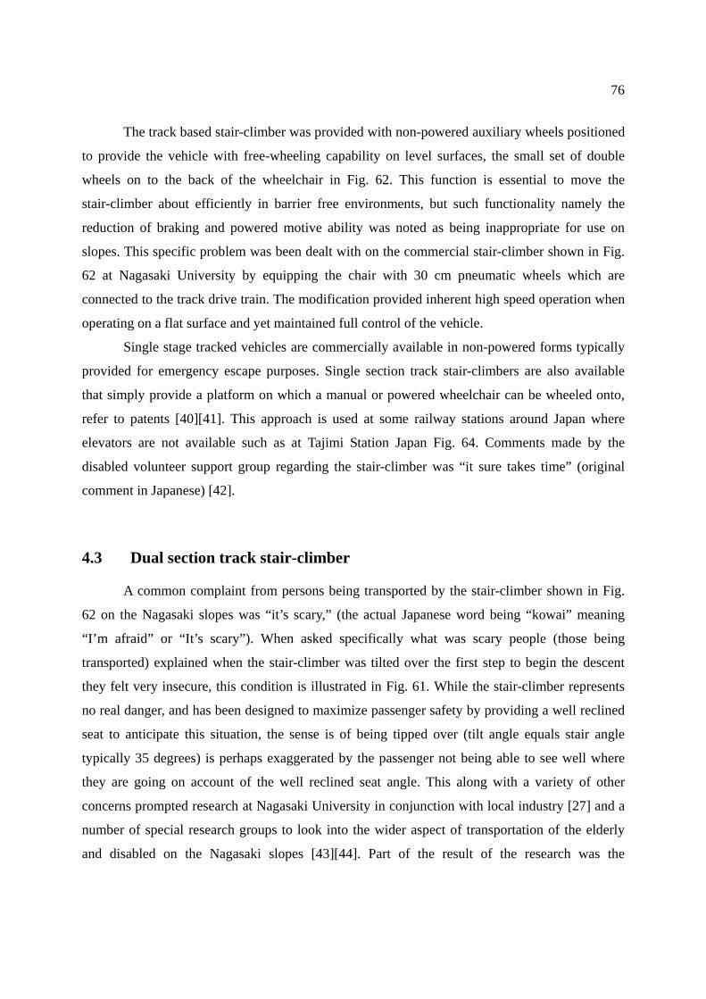
4.2 Single section track stair-climber ............................................................................. 73
4.3 Dual section track stair-climber ............................................................................... 76
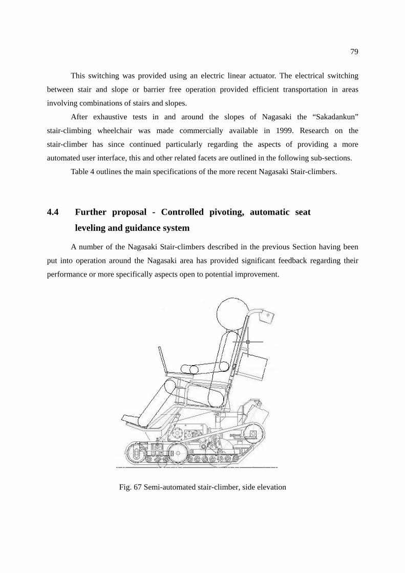
4.4 Further proposal - Controlled pivoting, automatic seat leveling and guidance system
.................................................................................................................................. 79
4.4.1 Pivoting and auto-seat leveling ....................................................................... 80
4.4.2 Control simplification ..................................................................................... 80
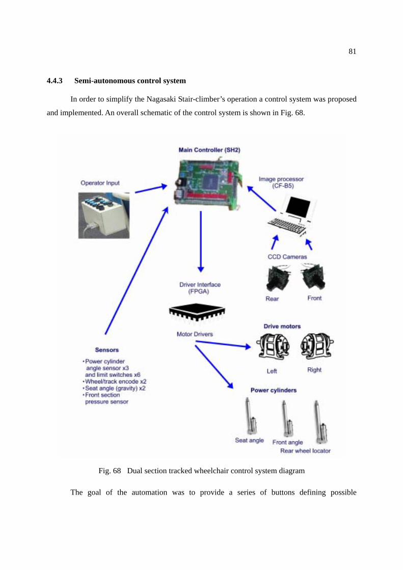
4.4.3 Semi-autonomous control system ................................................................... 81
4.4.4 Image processing based guidance system ....................................................... 83
4.5 Summary – track based mechanism....................................................................... 84
5 Discussion and Conclusion ............................................................................................... 87
Acknowledgments........................................................................................................................ 90
References .................................................................................................................................... 91
Curriculum Vitae......................................................................................................................... 94
Appendices ................................................................................................................................... 95
Page 4
1
Chapter 1 Introduction As we enter the second millennium since the time of Christ there is an increasing
mindfulness of the need to focus technology on helping people. This has been in part on account
of many countries currently experiencing what is referred to as an “aging population,” that is the
number of children born has continued to reduce over a long period of time. The result of this
along with many other factors has caused the need for a reducing number of care workers to care
for an increasing number of persons.
One specific area of need is that of providing increased freedom in terms of mobility for
the elderly or disabled. The reasons being to provide an optimum quality of life for the disabled
or elderly, and to reduce the load on care workers, the two aspects being closely linked by the
conscious sense of being a “burden”.
Autonomy in the area of mobility has always been highly valued, but is sometimes
impaired by some form of disability. In many cases this results in reliance on some form of
external transport mechanism. In this regard traditional wheelchairs and powered wheelchairs
continue to play a vital role. However wheelchairs to date provide a high level of mobility only in
artificial or “barrier free” environments. That is there remains a significant gap between the
obstacle negotiating ability of a wheelchair and that of the average able bodied person. This
aspect is perhaps most apparent when considering stair-climbing. While modern architecture and
new policies continue to make newly built areas as “accessible” as possible to persons with a
wide variety of disabilities steps will always be a reality in the “real world”.
This thesis focuses on the study of stair-climbing capable mechanisms for the elderly or
disabled. Common mobility assistive techniques and devices are outlined in this section and
recent advances in curb and stair climbing devices are outlined in Section 2. A proposal for a high
step stair-climbing mechanism targeted for wheelchair application is presented in Section 3.
Finally a practical track based stair-climbing mechanism is presented in Section 4
1.1 Why stairs?
The main focus of this paper revolves around the providing a personal means of
negotiating stairs, the first question that must be considered is why are stairs used. Stairs provide
Page 5
2
a means of ascent or descent. What alternatives are there to stairs? In terms of passive means
slopes are the primary alternative. When considering powered assistive mechanisms such as
escalators or lifts the range of alternatives is greater. The advantage of a slope (4.8 degrees max.
for manual wheelchair [1]) is that it does not significantly impede access to wheeled vehicles or
most walking assistive devices. However the two inherent disadvantages of a slope are the space
used compared to a set of stairs and the requirement that sufficient traction is present.
Firstly regarding space requirements. The conversion to, or addition of slopes (ramps) to
existing architecture is typically very costly and often negatively impacts the architecture with
regard to functionality (waste space) and aesthetics. In the case of a multi-level building a ramp is
usually not feasible. For example a 4.8 degree ramp providing access between floors (typically
2.7m) would require 32.5 meters of ramp. Assuming a ramp width of 90cm this would require
29.5 square meters of floor area, excluding access, exit and turning areas. The space required by a
standard (26cm tread, 18cm rise) stairway in the same situation would be 3.5 square meters, an
8.4 magnitude of spatial efficiency. This comparison is illustrated in Fig. 1 and Fig. 2.
Fig. 1 Anatomy of a typical stair (step height – riser 18cm, step depth – tread 26cm)
Fig. 2 A slope suitable for a manually propelled wheelchair
Page 6
3
Slope or ramp angles can be increased, however 4.8° has been deemed the maximum
angle for negotiation by the average user of a manually propelled wheelchair. In the case of a
powered wheelchair the recommended maximum angle is 7.1°. Local testing of powered
wheelchairs indicated maximum stable climb and descent rates of up to 20°, however the tests
were carried out in ideal conditions on high traction surfaces.
1.2 Stairs - are they safe?
Stairs represent spatial efficiency, and minimum risk in regard to slipping compared to
slopes, however stairs have come to be virtually representative of “barriers”. The term “barrier
free” is increasingly used in a broader context, however the basic concept originated from
reference to an environment that did not impede access to a manually propelled wheelchair.
Major impediments to wheelchair access have been and continue to be consideration for width
and the presence of steps or stairs.
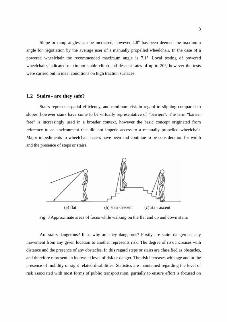
(a) flat (b) stair descent (c) stair ascent
Fig. 3 Approximate areas of focus while walking on the flat and up and down stairs
Are stairs dangerous? If so why are they dangerous? Firstly are stairs dangerous, any
movement from any given location to another represents risk. The degree of risk increases with
distance and the presence of any obstacles. In this regard steps or stairs are classified as obstacles,
and therefore represent an increased level of risk or danger. The risk increases with age and or the
presence of mobility or sight related disabilities. Statistics are maintained regarding the level of
risk associated with most forms of public transportation, partially to ensure effort is focused on
Page 7
4
areas of greatest risk to find means or ways to reduce the risk.
Secondly why are stairs dangerous? In the case of a flat pathway there is some risk that
any given person could fall and injure them self. In the case of stair negotiation careful
recognition of the location of the stair-edge is required. The height of the stair must be estimated,
and finally one’s feet located accordingly. This is illustrated in Fig. 3. Further the person’s shift in
Center of Gravity (COG) becomes complex compared to walking on a flat level surface. Raising
one’s weight to the level of each step takes the leg joint through an angle greater than that
experienced while walking. Weakening leg ability will be most apparent when going from a
seated to standing position, however following this the next most difficult task is often the
negotiation of stairs.
The task of climbing stairs according to basic physics requires more energy than descent,
however the control in stair descent is more difficult. More energy is required climbing stairs but
because the stairs are sloping upwards they are easier to see, therefore easier to negotiate and the
risk of injury in the case of a fall is reduced on account of the reduced potential fall angle. The
fall angle/ height is assumed in the forward direction as this is the direction of travel, falling
rearward is less common, and is often associated with slipping on slippery surfaces.
The task of descending stairs represents effort in regard to control. The visual distance to
the stair is greater, therefore negotiation becomes more difficult. Stair descent is further
complicated by the higher risk of injury in event of a fall on account of the increased fall angle/
height.
The stair inherently represents greater risk of injury on account of the presence of a stair
edge combined with the potentially increased fall angle/ height. The worst case fall angle during
descent on a typical stair (35°) would be 125° (90°+35°) compared with 55° (90°-35°) for stair
ascent.
1.3 Wheeled mobility
The wheeled vehicle has perhaps been one of man’s most important technical discoveries,
early evidence dates back to around 3000 BC. in the Tigris-Euphrates Valley [2], a painting of
early wheels are shown in Fig. 4 [3].
No doubt since early times access to areas with steps would have presented similar
Page 8
5
challenges as the present day. However in the area of providing personal mobility that is not
significantly limited by terrain the approach employed in early civilization has yet to be rivaled,
that is carriage by a group of two or more persons. While such as the ancient Pharaohs may not
have lacked in personal assistants they did perhaps lack a valid need to be carried from place to
place. The current generation of elderly and disabled do however typically lack in personal
assistants and do have a valid reason to be assisted in the area of personal mobility.
Fig. 4 A painting showing primitive wheels
Picture courtesy of education.eth.net
The approach used by early civilizations has fundamentally not changed in the area of
personal mobility, that is the use of wheeled vehicles in relatively flat environs and carriage by
people or animals in areas not suited to wheeled vehicles.
1.4 Wheels and stairs
(a) mobility scooter tire (b) standard wheelchair tire (c) early wheelchair tire
Fig. 5 Variation of wheel diameter in regard to stair negotiation (tread depth = 26cm)
Stairs perhaps best represent “environs not suited to wheeled vehicles”. The step function
of a stair versus the sinusoidal function of the wheel is illustrated in Fig. 5. Two fundamental
means of stair negotiation are provision of a stepping mechanism, or increasing the wheel’s
Page 9
6
footprint (diameter) so that the step is in effect bridged. Provision of a stepping mechanism
requires relatively complex mechanical operation and must be linked to knowledge of the
location of the stair edge. Human negotiation of stairs would be categorized as such.
The second basic approach is to in effect increase the forward-rear footprint of the vehicle
so that it bridges the stairs. This can be made possible by increasing the wheel diameter or by
using some form of tracked operation, which in effect emulates a wheel with an infinitely large
radius.
The relative advantages and disadvantages of these two approaches to stair negotiation are
that stepping places weight on the stair’s tread, which is where it is designed to be and involves
no increased risk of slip, that is the risk of slip is no more or less than that on a flat pathway,
however the major disadvantage is it requires knowledge regarding the stair edge. A tracked
approach has the major advantage in that it bridges the stairs and therefore prior knowledge of the
stair-edges is not required. However the major disadvantage is that the vehicle weight rests on the
edge of the stair, this therefore requires stairs to have robust edges, further the track must be
provided with a means to prevent slipping.
Variation of wheel diameter is illustrated in Fig. 5, Fig. 5(a) represents a large scooter or
small powered wheelchair wheel of diameter 30cm. Fig. 5(b) represents the diameter of a
standard manually propelled wheelchair’s rear wheel of 58cm and Fig. 5(c) shows a 1 meter
diameter wheel as used on some early wheelchairs.
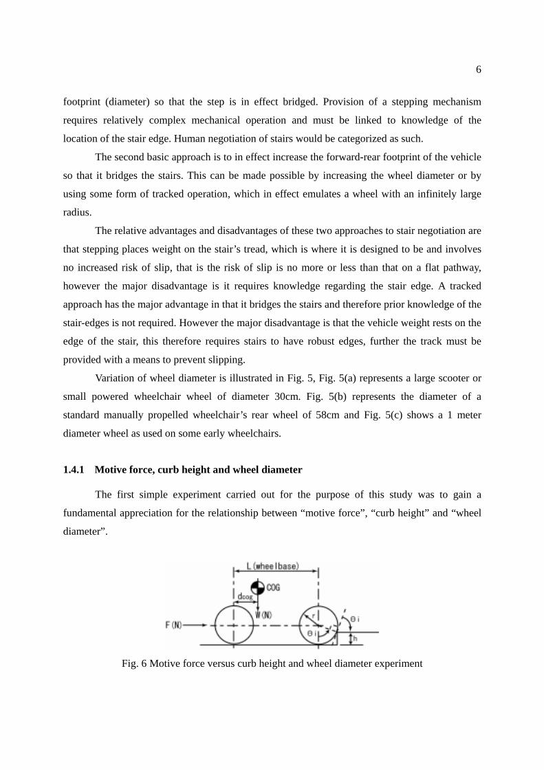
1.4.1 Motive force, curb height and wheel diameter
The first simple experiment carried out for the purpose of this study was to gain a
fundamental appreciation for the relationship between “motive force”, “curb height” and “wheel
diameter”.
Fig. 6 Motive force versus curb height and wheel diameter experiment
Page 10
7
The vehicle used for the experiment was a 3 wheel mobility scooter. Force F(N) was
applied at the rear of the scooter approximately in line with the rear axle as shown in Fig. 6. The
measured force was normalized to fr by dividing the weight (vertical force) measured at the front
axle by the F(N) value. The experimental results are graphed in Fig. 7 for two different tire
pressures. The continuous line on the graph shows the calculated value based on equation 1. The
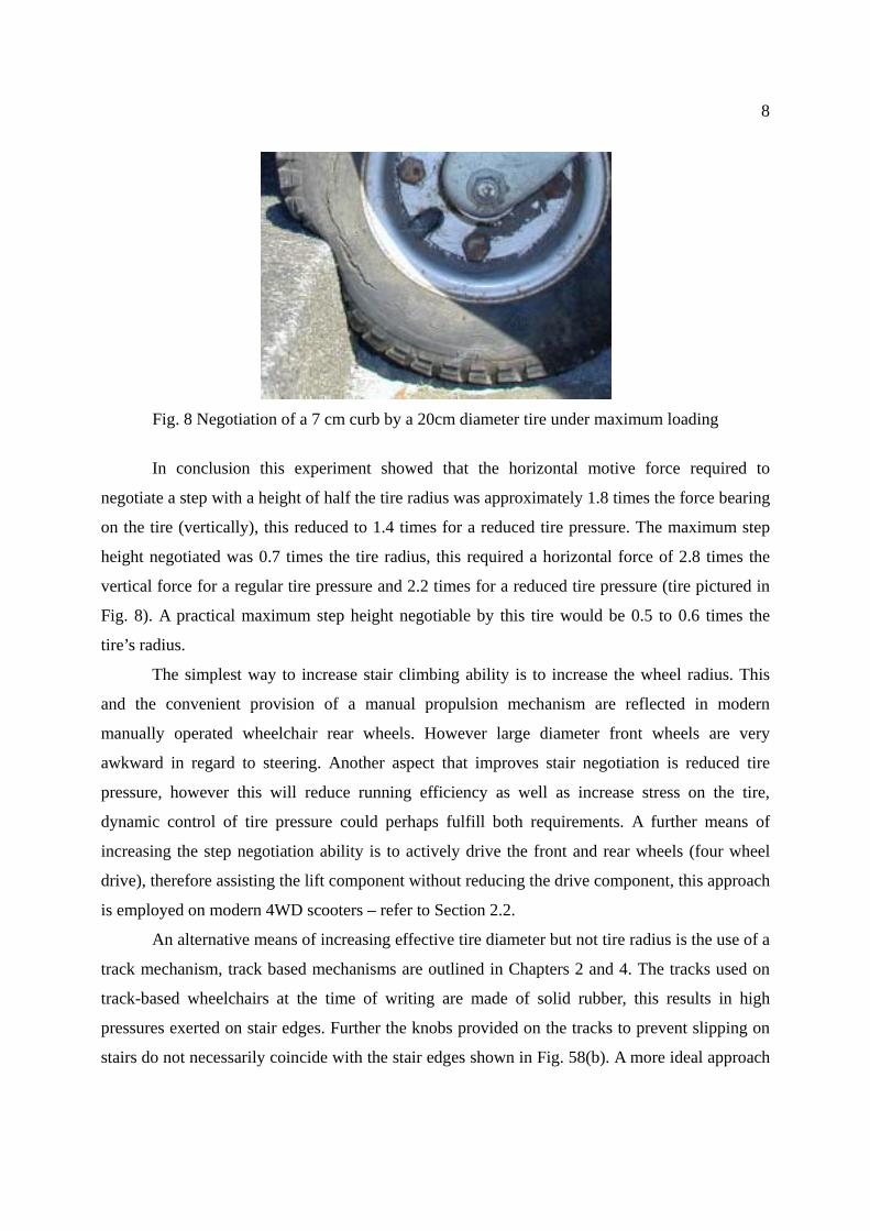
front tire of the scooter is shown negotiating a 7 cm curb under maximum loading in Fig. 8.
)(costan 1
rhrfr −
= − (1)
Where fr = relative motive force
r = wheel radius that is 1/2 the diameter
h = curb height
Fig. 7 Motive force required to negotiate various curb heights for a fixed wheel diameter
It must be noted that equation (1) does not account for any softness in the tire, clearly the
lower tire pressure makes curb negotiation easier, however reduces running efficiency. A relative
force of fr = 1 means motive force (horizontal) equals the weight (vertical force) bearing on the
front tire.
Page 11
8
Fig. 8 Negotiation of a 7 cm curb by a 20cm diameter tire under maximum loading
In conclusion this experiment showed that the horizontal motive force required to
negotiate a step with a height of half the tire radius was approximately 1.8 times the force bearing
on the tire (vertically), this reduced to 1.4 times for a reduced tire pressure. The maximum step
height negotiated was 0.7 times the tire radius, this required a horizontal force of 2.8 times the
vertical force for a regular tire pressure and 2.2 times for a reduced tire pressure (tire pictured in
Fig. 8). A practical maximum step height negotiable by this tire would be 0.5 to 0.6 times the
tire’s radius.
The simplest way to increase stair climbing ability is to increase the wheel radius. This
and the convenient provision of a manual propulsion mechanism are reflected in modern
manually operated wheelchair rear wheels. However large diameter front wheels are very
awkward in regard to steering. Another aspect that improves stair negotiation is reduced tire
pressure, however this will reduce running efficiency as well as increase stress on the tire,
dynamic control of tire pressure could perhaps fulfill both requirements. A further means of
increasing the step negotiation ability is to actively drive the front and rear wheels (four wheel
drive), therefore assisting the lift component without reducing the drive component, this approach
is employed on modern 4WD scooters – refer to Section 2.2.
An alternative means of increasing effective tire diameter but not tire radius is the use of a
track mechanism, track based mechanisms are outlined in Chapters 2 and 4. The tracks used on
track-based wheelchairs at the time of writing are made of solid rubber, this results in high
pressures exerted on stair edges. Further the knobs provided on the tracks to prevent slipping on
stairs do not necessarily coincide with the stair edges shown in Fig. 58(b). A more ideal approach
Page 12
9
would perhaps be the realization of pneumatic (tire) tracks, thereby spreading pressure over a
larger area at the point of contact with each stair edge. A deformable track has been proposed in
[4], this is depicted in Fig. 20(a) and (b) and the concept illustrated in Fig. 20(c).
This simple experiment accounted only for static loading considerations, the results of a
study of dynamic considerations for curb negotiation for manually propelled wheelchairs is
provided in [5].
1.5 Requirements for stair-climbing mobility
Climbing a set of stairs presents two central issues, firstly the actual climbing or
negotiating of each single step, and secondly providing stability for the overall mechanism while
on the stairs. In the case of an able bodied person a stepping mechanism is provided in the form
of legs and a very precise balance mechanism is provided by the brain in conjunction with a
variety of sensory systems. The legs are equipped with high speed and high peak power output
actuators in the form of muscles. The brain acts on a combination of visual data (estimation of
stair location and height) and tactile/ pressure sensory data (feedback) from the legs and balance
sensors associated with the ears/ brain, this provides a closed control loop.
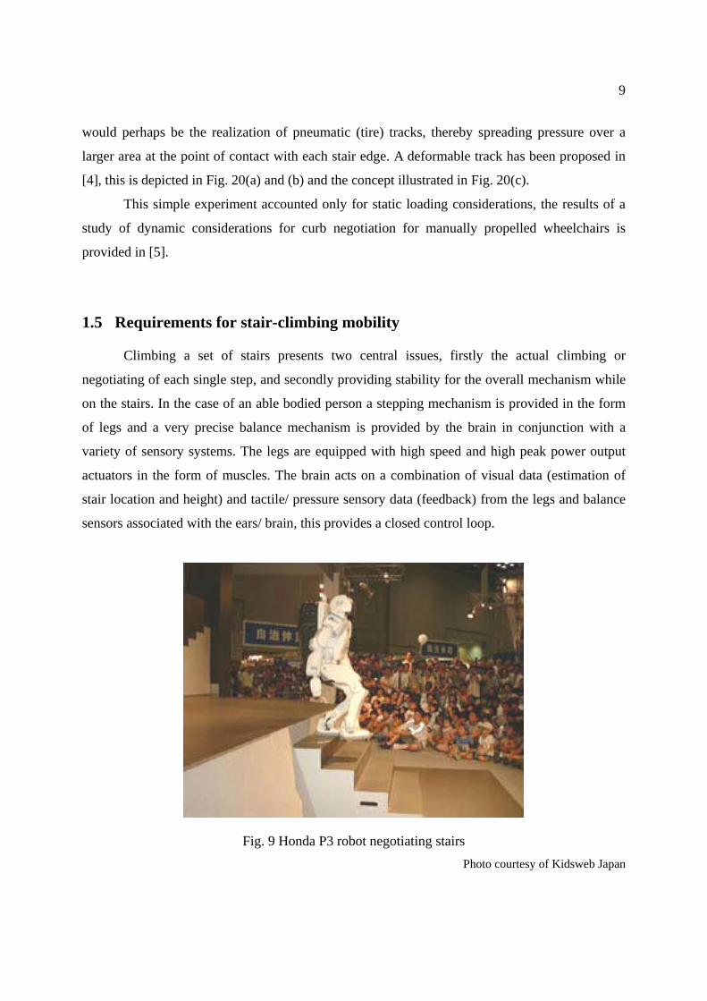
Fig. 9 Honda P3 robot negotiating stairs Photo courtesy of Kidsweb Japan
Page 13
10
The very complex task of load balancing so as to maintain a correct COG (center of
gravity) during the stair negotiation is carried out almost as a subconscious task. The muscles
provide the high speed and high peak power actuation necessary to correct any sensed error in
balance. This complex task has been emulated in the world of robotics by such as the Honda P3
robot pictured in Fig. 9 [6], control mechanism and algorithms detailed in such patents as [7] and
[8].
Regarding stability orders of magnitude, for a person in a static standing position, forward
– rear stability is in the order of 6°. That is for example in the case of an average height person of
say 173cm, the COG at say 105cm (~waist line) and with a toe to heel load bearing range of say
23cm (actual foot length measurement of say 26cm). This case calculates to give a ~12° range of
stability therefore giving a maximum stability margin of 6° when centered. Worst case static
stability reduces to around 2° (side to side) when standing on one foot. The calculation of
dynamic stability margins during a walking or stair climbing gait is however significantly more
complex.
In order to provide an assistive mobility device suitable for negotiation of stairs a
mechanism capable of negotiating stairs must be provided, two approaches are presented in this
thesis, proposed use of articulated wheel cluster technology and a practical track based
mechanism. Another aspect is the provision of a balance mechanism giving acceptable stability
margins. During stair climbing the provision of acceptable stability at all times is paramount in
regard to safety, and therefore in the public acceptance of any form of stair climbing assistive
device/s. Finally in the case of a wheelchair a constant seat angle is preferred.
The two basic approaches to stability are similar to the modes of stability used in modern
vehicles. Stability may be provided inherently by providing three or more points of contact with
the ground at all times, the common car is such an example. Two points of contact is possible if a
balance mechanism is used as in the case of say a rickshaw (external balance mechanism -
person), or an internal balance mechanism such as in the case of a bicycle or motorcycle. A
bicycle’s or motorcycle’s internal balance mechanism is the person controlling it, the person
needs only control the vehicle’s lateral motion so as to maintain the appropriate COG (center of
gravity). A single point of contact with the ground is possible also using external or internal
balance mechanisms such as in the case of the common wheelbarrow or unicycle, however in the
case of a single point of contact with the ground both the provision of both front to rear and side
Page 14
11
to side balance simultaneously becomes a relatively complex task.
Applying the above examples to mobility assistive devices on stairs, four points of contact
with the ground at all times will provide inherent static stability, however it is difficult to achieve
due to the nature of stairs, particularly in regard to the front to rear height differential that occurs.
By using a laterally stable device and employing a personal assistant, or a nearby hand rail to
provide the balance mechanism the problem of front to rear height differential may be resolved,
however the system becomes reliant on the assistant or provision of the right kind of handrails.
The two stair-climbing mechanisms outlined in this thesis are based on the provision of
inherent static stability.
1.6 Common stair-climbing techniques and assistive devices
1.6.1 Assistant based curb, slope and stair negotiation techniques
(a) single person (b) 4 person stair ascent (c) 4 person stair descent
Fig. 10 Stair-climbing – current techniques
Two common care-worker/ assistant based approaches to negotiating stairs are shown in
Fig. 10(a) carrying a person on one’s back and Fig. 10(b) and (c), carrying a person in a
lightweight wheelchair. Carrying an elderly or disabled person on ones’ back represents a very
efficient and cost effective approach however it also presents high risk of injury for both persons,
back injury is often associated with long term care – despite using all the “right” lifting
Page 15
12
techniques, and combined with the risk of suffering a fall [9].
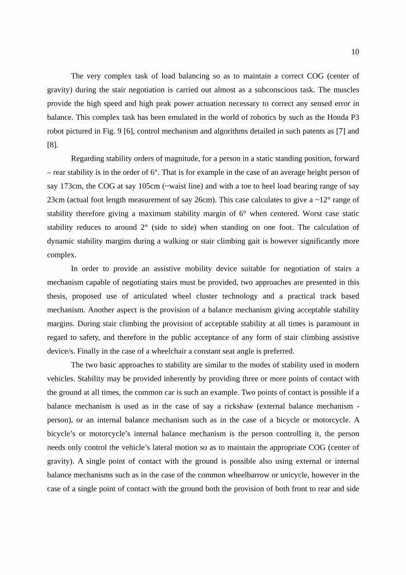
(a) Curb negotiation (b) Stair descent 3 persons
Fig. 11 Curb and stair negotiation – current techniques
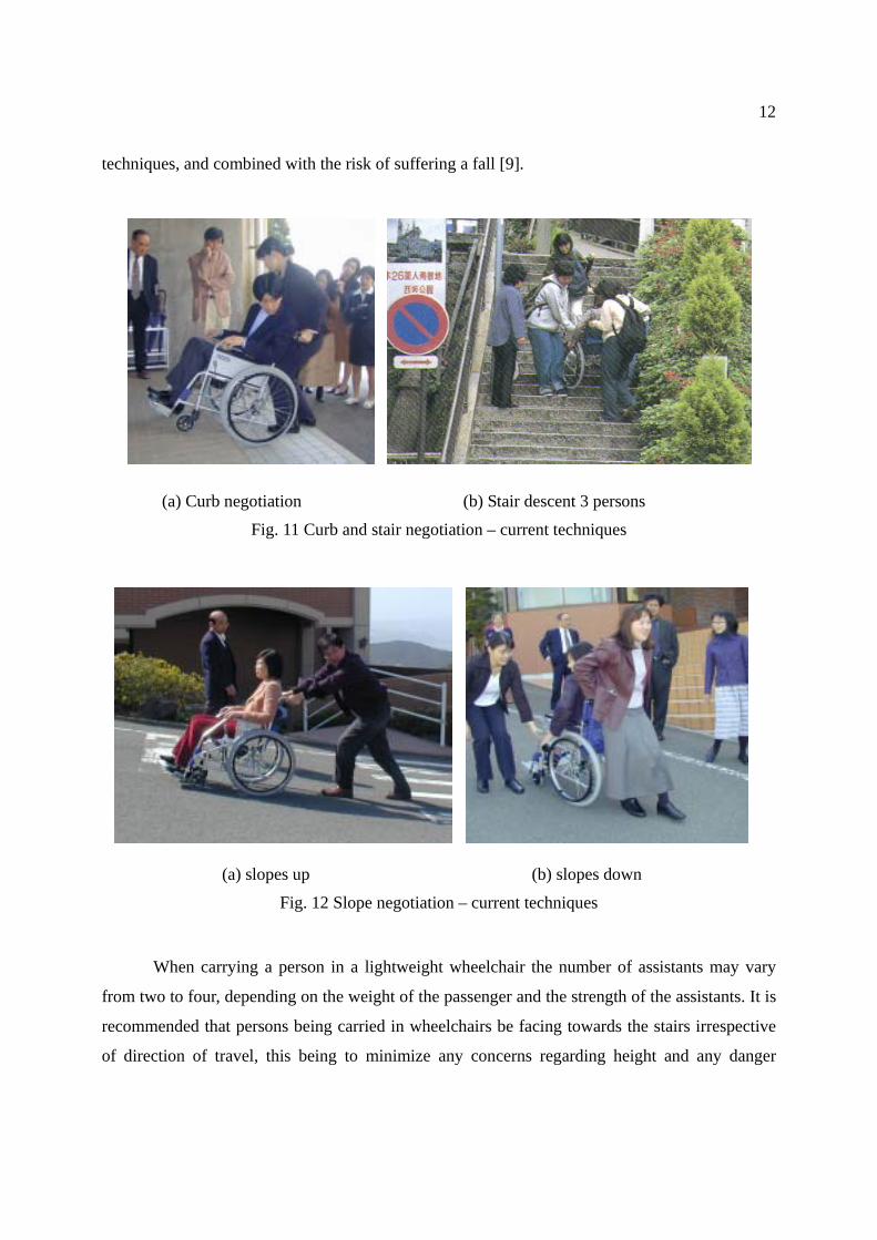
(a) slopes up (b) slopes down
Fig. 12 Slope negotiation – current techniques
When carrying a person in a lightweight wheelchair the number of assistants may vary
from two to four, depending on the weight of the passenger and the strength of the assistants. It is
recommended that persons being carried in wheelchairs be facing towards the stairs irrespective
of direction of travel, this being to minimize any concerns regarding height and any danger
Page 16
13
should the passenger slip out of the chair. This is shown in Fig. 10(b) stair ascent and Fig. 10(c)
stair descent. The negotiation of curbs or single steps is possible with a single assistant as shown
in Fig. 11(a), this will also depend on the relative weight of the passenger and strength of the
assistant. The negotiation of slopes is shown in Fig. 12(a) for ascent and Fig. 12(b) for descent. In
Fig. 12(b) the assistant is facing down the slope this is noted as being a matter of personal
preference [10].
1.6.2 Common stair-climbing and van entry assistive devices
Lifts are perhaps the most common means of providing access between floors. Lifts are
typically very expensive and consume significant space. Low cost compact lifts targeted for
residential use however are also available [11]. For negotiation of a small number of stairs for
example the entrance to many western homes (porch) or the high initial step to Japanese homes
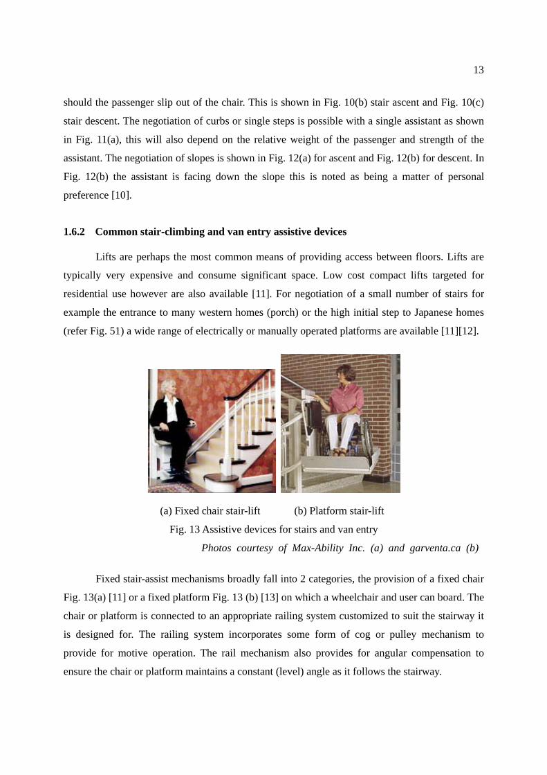
(refer Fig. 51) a wide range of electrically or manually operated platforms are available [11][12].
(a) Fixed chair stair-lift (b) Platform stair-lift
Fig. 13 Assistive devices for stairs and van entry
Photos courtesy of Max-Ability Inc. (a) and garventa.ca (b)
Fixed stair-assist mechanisms broadly fall into 2 categories, the provision of a fixed chair
Fig. 13(a) [11] or a fixed platform Fig. 13 (b) [13] on which a wheelchair and user can board. The
chair or platform is connected to an appropriate railing system customized to suit the stairway it
is designed for. The railing system incorporates some form of cog or pulley mechanism to
provide for motive operation. The rail mechanism also provides for angular compensation to
ensure the chair or platform maintains a constant (level) angle as it follows the stairway.
Page 17
14
Customization and significant on site work makes fixed stair-assist mechanisms very
expensive and dedicated to a given set of stairs. The chair or platform is usually designed to fold
up to minimize waste space while not in use. The fixed platform is perhaps the most common
stair-assist mechanism used in public areas where lifts are not available. Alternative approaches
include the use of overhead hoists (Section 2.8) Fig. 28(a).
(a) Portable wheelchair lifter platform (b) Retrofit wheelchair only lift
Fig. 14 Van access mechanisms Photos courtesy of Sanwa Co. Ltd (a) and americanwheelchairs.com (b)
In regard to assisting wheelchair access to vans a range of portable fold-up ramps are
available [14], portable ramps can also be used for the negotiation of a small number of stairs. Fig.
14(a) shows a manually operated portable lifting platform [15], a more compact wheelchair only
lifter is outlined in Section 2.8 and pictured in Fig. 28(b). A wide range of retrofit type lifters are
available to provide van access for wheelchairs [16]. An electric hoist type wheelchair lifter is
shown in Fig. 14 (b) [14].
Many vehicle manufactures offer a wide range of custom options at the time of new
vehicle purchase. The provision of a seat which swivels out has become an option made available
by most Japanese car manufactures, however the task of transfer to such as a wheelchair remains.
One solution to this problem has been the provision of a seat which doubles as an assistant
operated wheelchair is outlined in Section 2.8 and pictured in Fig. 28(c). The more traditional
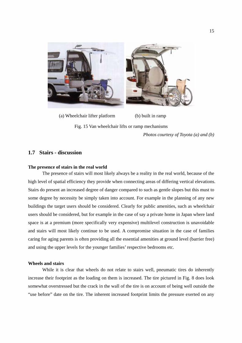
option of a built in wheelchair lift is shown in Fig. 15(a) and a built in ramp system Fig. 15(b).
While the built in options provide very elegant solutions they are very expensive and dedicated to
a given vehicle.
Page 18
15
(a) Wheelchair lifter platform (b) built in ramp
Fig. 15 Van wheelchair lifts or ramp mechanisms
Photos courtesy of Toyota (a) and (b)
1.7 Stairs - discussion
The presence of stairs in the real world The presence of stairs will most likely always be a reality in the real world, because of the
high level of spatial efficiency they provide when connecting areas of differing vertical elevations.
Stairs do present an increased degree of danger compared to such as gentle slopes but this must to
some degree by necessity be simply taken into account. For example in the planning of any new
buildings the target users should be considered. Clearly for public amenities, such as wheelchair
users should be considered, but for example in the case of say a private home in Japan where land
space is at a premium (more specifically very expensive) multilevel construction is unavoidable
and stairs will most likely continue to be used. A compromise situation in the case of families
caring for aging parents is often providing all the essential amenities at ground level (barrier free)
and using the upper levels for the younger families’ respective bedrooms etc.
Wheels and stairs While it is clear that wheels do not relate to stairs well, pneumatic tires do inherently
increase their footprint as the loading on them is increased. The tire pictured in Fig. 8 does look
somewhat overstressed but the crack in the wall of the tire is on account of being well outside the
“use before” date on the tire. The inherent increased footprint limits the pressure exerted on any
Page 19
16
given point of the stair, particularly the stair edge. In this regard “pneumatic tires” are better
suited than say solid rubber tires to stair negotiation, as well as providing a smoother ride for the
user. The curb negotiating ability of a wheel is mainly related to tire radius and secondarily the
softness (deformability) of the tire. A track based alternative emulates a tire of infinite radius and
is inherently well suited to stairs but the realization of a deformable (soft) track necessary to
provide a stair edge friendly and non-slip tread is difficult.
Assistive techniques or devices Personal autonomy is regarded highly in today’s society but remains largely unrealized
for mobility disabled persons. Current common practice in regard to stair assistance is that two to
four assistants are required for a mobility disabled person say in a wheelchair to negotiate a set of
stairs. Assistive device based solutions for stair-negotiation include lifts and chair or platform
based stair-lift mechanisms. Wheelchair access to vans can be provided by a portable or built in
ramp, a portable platform lifter or a range of built in or retrofitable lifting mechanisms.
Fixed stair-assist or high step mechanisms
Regarding fixed stair-assist or high step mechanisms, in many cases the provision of such
will be an integral part of the initial design. For example, many vans are dedicated to the
transportation of wheelchair users, and as such the reduction of any potential multipurpose role
would not be of any consequence. However conversion or retrofitting an existing entrance,
stairway or vehicle for wheelchair users is often very difficult and expensive.
1.8 Thesis outline
This thesis focuses on the development of stair-climbing and van access assistive
mechanisms. Chapter one outlined why steps are necessary, safety on stairs, how wheels relate to
stairs, the requirements for stair-climbing and current common approaches or devices used to
mobilize elderly or disabled persons in “barrier present” environments.
Chapter 2 outlines recent advances in mobility assistive mechanisms available at the time
of writing. The main focus is on curb negotiation, stair-climbing, and high step assistive devices.
High steps are noted as being common in the boarding of such as a van and in the case of Japan
Page 20
17
the first step to most traditional Japanese homes.
Chapter 3 outlines a proposal for a high step capable stair-climbing mechanism targeted
for wheelchair application. The mechanism is based on a chair connected to respective front and
rear clusters of wheels. The front and rear wheel clusters are then connected to the chair base via
two controlled articulated links. The unique functionality provided include stair negotiation in the
desired direction of travel and the ability to directly enter such as a van or Japanese home without
the need for any special equipment.
Chapter 4 outlines the development of a very practical stair-climbing mechanism based on
dual section track operation. The stair-climbing wheelchair was trailed on the slopes of Nagasaki
and having found favor with the locals has been made commercially available. The two section
track mechanism provides a robust and reliable means to negotiate highly irregular stairs with
relative simplicity. The prototyping of a guidance and control system for the track based
wheelchair is outlined.
Chapter 5 provides an overall discussion and concluding remarks.
Page 21
18
Chapter 2 Recent advances in mobility assistive
devices for stairs or curbs This Section provides an overview of recent advances in mobility assistive devices
available for curbs or stairs at the time of writing. The coverage focuses on the curb or stair
climbing ability of the devices.
2.1 Curb assistive mechanisms for wheelchairs
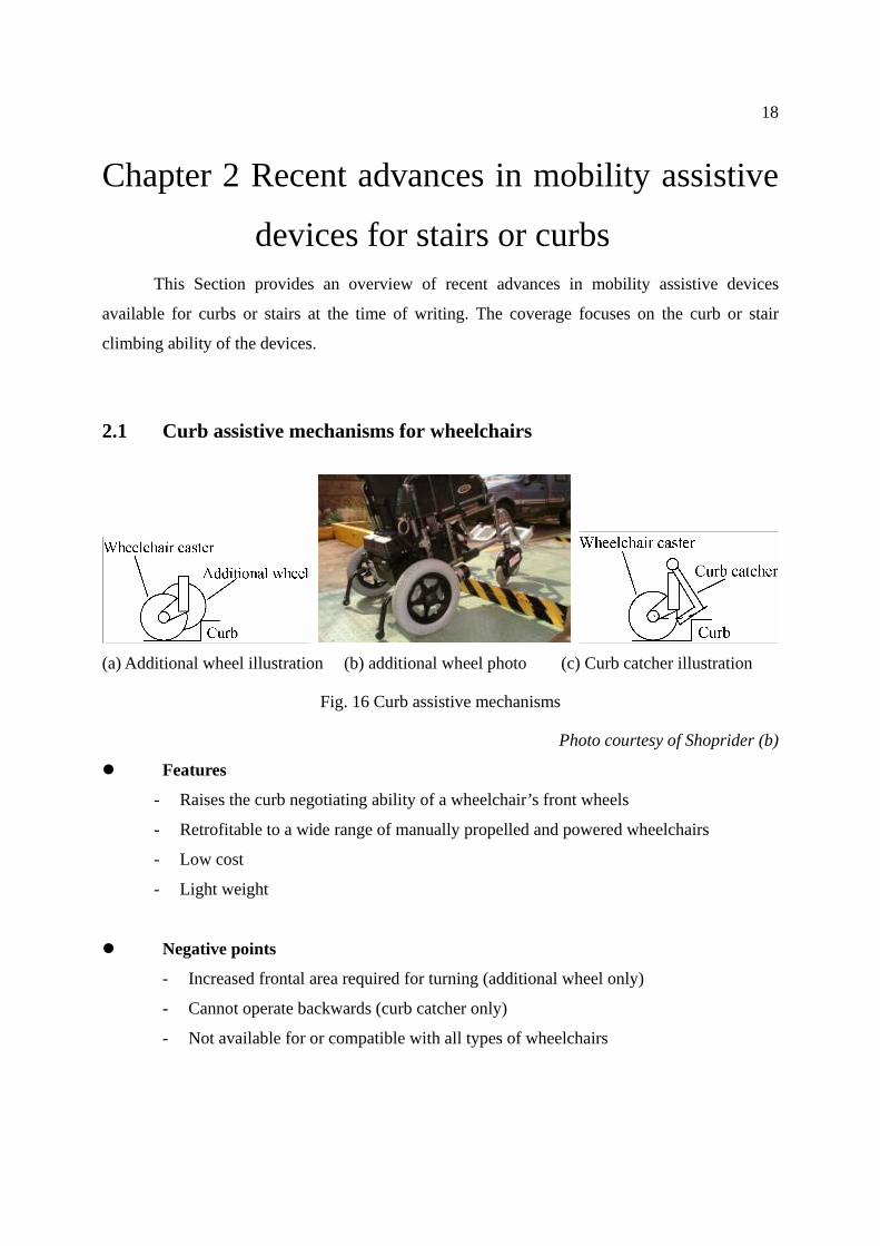
(a) Additional wheel illustration (b) additional wheel photo (c) Curb catcher illustration
Fig. 16 Curb assistive mechanisms
Photo courtesy of Shoprider (b)
Features
- Raises the curb negotiating ability of a wheelchair’s front wheels
- Retrofitable to a wide range of manually propelled and powered wheelchairs
- Low cost
- Light weight
Negative points
- Increased frontal area required for turning (additional wheel only)
- Cannot operate backwards (curb catcher only)
- Not available for or compatible with all types of wheelchairs
Page 22
19
Comments
At the time of writing a number of curb assisting devices are available for manually
propelled and powered wheelchairs. One such device provides additional wheels mounted on the
front wheel caster assemblies [17]. The additional wheels are positioned a little forward and
higher than the wheelchair’s casters so as to hit the curb first and raise the front of the wheelchair
and enable easier negotiation of curbs. This is illustrated in Fig. 16(a) and depicted in Fig. 16(b).
Another device is the positioning of a hinged curb catcher as shown in Fig. 16(c). The curb
catcher hits the curb and rotates as shown by the dotted line resulting in lifting the front of the
wheelchair enabling negotiation curbs.
2.2 Curb capable powered wheelchairs and mobility scooters
(a) 150mm curb wheelchair (b) 120mm curb 4WD scooter
Fig. 17 Curb capable mobility assistive devices
Photos courtesy of A1 mobility (a), and Serio-Japan (b)
Features
- High curb negotiating ability (150cm powered wheelchair/ 120cm mobility scooter)
- High level of mobility in most environments
- High level of stability (cf. manually propelled wheelchair)
- Easy to operate (mobility scooter only)
Page 23
20
Negative points
- Large turning circle (mobility scooter only)
- Joystick operation difficult (powered wheelchair only)
- Heavy (therefore very difficult to assist with stairs or van entry without special
equipment)
Comments
Persons with limited upper limb ability have traditionally used such as a fully powered
wheelchair, however the task of controlling a powered wheelchair is relatively difficult and
research continues toward simplifying this task refer to [18]-[21]. The powered wheelchair shown
in Fig. 17(a) [22] is designed to negotiate curbs up to 150mm, the front wheels (anti-tip device)
are adjustable in height and are raised when curb negotiation is required. Mobility scooters such
as that shown in Fig. 17(b) [23] have become increasingly popular for both elderly and disabled
persons, part of the reason for increased popularity is they are easier to control compared to the
powered wheelchair and seem to have gained greater acceptance by the public compared to the
powered wheelchair. While both powered wheelchairs and mobility scooters provide excellent
general purpose mobility their weight makes assistance with stairs or van entry without special
equipment very difficult. A wide variety of lifting mechanisms are available, however at
significant cost and tradeoff in terms of space etc (refer to Sections 1.6.2 and 2.8).
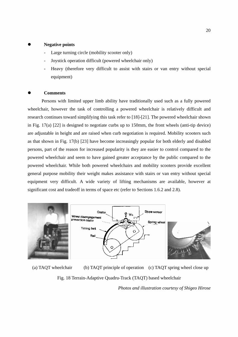
(a) TAQT wheelchair (b) TAQT principle of operation (c) TAQT spring wheel close up
Fig. 18 Terrain-Adaptive Quadru-Track (TAQT) based wheelchair
Photos and illustration courtesy of Shigeo Hirose
Page 24
21
A 4WD mechanism provides improved curb negotiation compared to 2WD (2 wheel
drive) operation, however a 4WD mechanism is not well suited to stairs for 3 fundamental
reasons. Firstly the lack of necessary traction, secondarily the change of vehicle angle during the
stair climb reduces the vehicles stability to unacceptably low levels and finally in the case of a
vehicle propelling a person such as a wheelchair the seat angle should ideally remain relatively
constant. A prototype mechanism dealing with all of these issues is outlined in [24]. The
Terrain-Adaptive Quadru-Track (TAQT) based wheelchair prototype is pictured in Fig. 18(a), the
principle of COG modification illustrated in Fig. 18(b) and a close up of a wheel (spring loaded)
gripping a stair edge is shown in Fig. 18(c).
2.3 Track based stair-climbers
(a) Autonomous stair-climbing wheelchair (b) Stair-climbing wheelchair transporter
Fig. 19 Modern single track based stair-climbers
Photos courtesy of Hospimedica group
Features
- Stair-climbing ability
- Autonomous stair-climbing possible (autonomous stair-climbing wheelchair only)
- Suitable to most outdoor stairs and some indoor stairs
- Simple operation (cf. non-track based stair-climbing mechanisms)
Page 25
22
- Provides stair-climbing ability for standard wheelchairs (transporter only)
- Provides for general purpose off stair operation (autonomous stair-climbing
wheelchair only)
Negative points
- Must climb stairs backwards
- Special mechanisms required for off stair operation and changing to and from
stair-climb angle
- Non slip mechanism required when on stairs (tread/ knobs), asynchronism between
stair edges and tread/ knobs results in high non linear pressures exerted on stair
edges
- Unsuitable for most indoor stairs and some outdoor stairs
- Heavy (cf. standard power wheelchair - autonomous stair-climbing wheelchair only)
Comments
Tracked climbers are dealt with in more detail in Section 4. A modern single tracked fully
autonomous stair-climber and powered wheelchair is shown in Fig. 19(a) and a platform used to
carry a wheelchair and user up or down stairs is shown in Fig. 19(b) [25]. An older technology
single track stair-climber is shown in Fig. 62 (powered stair-climber – free wheeling on the flat)
and Fig. 64 (tracked stair-climbing wheelchair transporter operating at a station in Japan). The
central advantage of the use of tracks is the independence or robustness regarding the type of stair
or surface being negotiated. Disadvantages of track based operation include the high pressure
exerted on the stair edges therefore limiting use to stairs with appropriately robust leading edges.
An anti-slip mechanism is required while on the stairs and a mechanism is required to ensure the
device changes to and from the stair angle in a controlled manner at the top of stairs.
Regarding the most fundamental track based problem, that of the high pressure exerted on
the stair edges a deformable track has been proposed and modeled in [4]. The track consists of
deformable or hysteresis blocks configured as shown in Fig. 20(a). The principle of operation is
shown in Fig. 20(c), namely to spread the stair edge load over a larger area as well as inherently
provide a means to prevent slipping that is not reliant on the track tread (knobs) synchronizing
with the stair edges. This compares with a regular wheelchair track as depicted in Fig. 58(a),
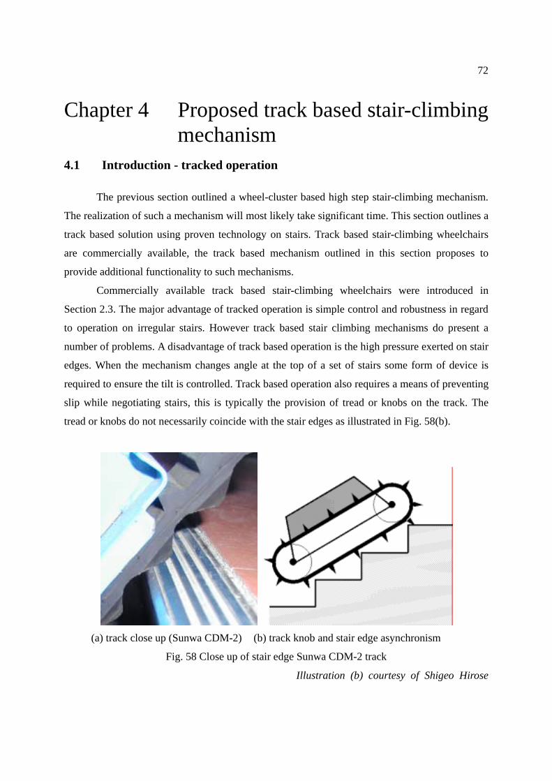
illustrated in Fig. 58(b) and discussed in Chapter 4.
Page 26
23
(a) XEVIUS tracks (b) XEVIUS track close up (c) XEVIUS track principle
Fig. 20 Xero-Viscous Upstair Service (XEVIUS) deformable tracks
Photo and illustration courtesy of Shigeo Hirose
2.4 Lightweight wheelchair stair-climbing attachments
(a) Stair-climb mech. (b) Mech. attached to wheelchair (c) Stair-climbing operation
Fig. 21 Scalamobile – stair-climbing attachment
Features
- Stair-climbing ability
- Suitable to almost all stairs (max. step height up to 25cm Scalamobile/ 21cm C-max )
- Compact
- Uses existing wheelchair – no transfer required (Scalamobile only)
- Lightweight (~25Kg plus wheelchair Scalamobile/ ~32Kg total C-max)
Page 27
24
Negative points
- Requires special instruction regarding usage (Scalamobile only)
- Dedicated assistant operated wheelchair – transfer required (C-max only)
- Orbital motion tends to be uncomfortable for passengers (Scalamobile)
- Auto-brake mechanism does not suit roughly surfaced stairs
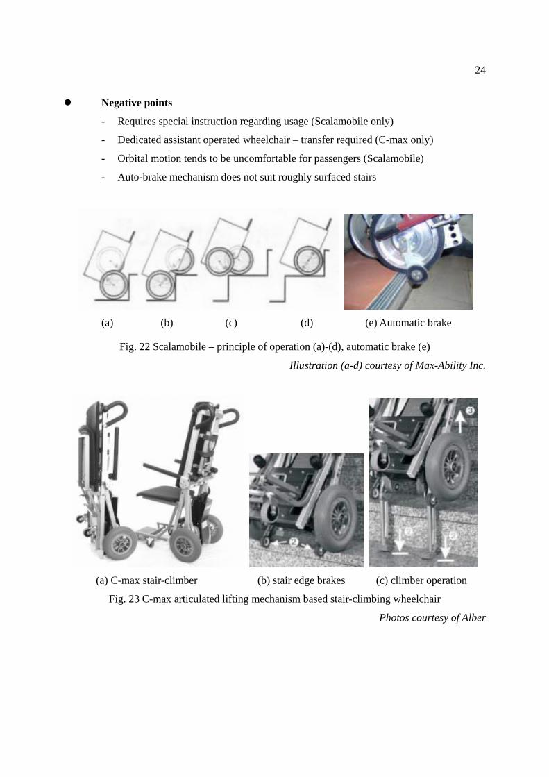
(a) (b) (c) (d) (e) Automatic brake
Fig. 22 Scalamobile – principle of operation (a)-(d), automatic brake (e)
Illustration (a-d) courtesy of Max-Ability Inc.
(a) C-max stair-climber (b) stair edge brakes (c) climber operation
Fig. 23 C-max articulated lifting mechanism based stair-climbing wheelchair
Photos courtesy of Alber
Page 28
25
Comments
The addition of stair-climbing functionality by necessity increases a wheelchair’s weight,
however by making this functionality modular and easily removable from the wheelchair it can
be attached only when required (Scalamobile) Fig. 21 [26]. Two pairs of wheels operate on
separate axes, the orbiting motion is shown in Fig. 22(a)-(d). The C-max wheelchair operates in a
similar manner to the Scalamobile except one pair of wheels is replaced with lifting protrusions
as shown in Fig. 23(c). The respective stair edge auto brake mechanisms are pictured in Fig.
22(e) and Fig. 23(b).
The stair-climber described in Section 4 and pictured in Fig. 66(c) technically qualifies as
a stair-climbing attachment. This stair-climber (KSC-C-10) has been developed by Kyowa
Industries [27] in conjunction with Nagasaki University and associated research groups [28]. The
operation is smooth and easy to operate. However the size and weight of the stair-climbing unit is
much greater than such as the Scalamobile or C-max.
2.5 Wheel cluster based stair-climbers
(a) three wheel cluster (b) four wheel cluster
Fig. 24 Powered single cluster stair-climbers
Photos courtesy of Hospimedica group and runsoft.com.cn
Page 29
26
Features
- Stair-climbing ability
- Suitable to almost all stairs
- Compact
- Operate as general purpose powered wheelchairs
- Lightweight (cf. track based wheelchairs)
Negative points
- Requires assistance (one person) for stair operation
- Orbital stair-climbing operation may be uncomfortable for passengers
(a) barrier free mode (b) stair-climb configuration
Fig. 25 Wheel cluster based stair-climber with articulated balancing sliders
Illustrations courtesy of US Patent 6,484,829 B1
Page 30
27
Comments
Wheel clusters in their simplest form adapt the most common means of transportation
“the wheel” to the most common obstacle to the wheel “the stair”. If a single wheel cluster is
used, a balancing mechanism is required for any form of stair-climbing. The term “Single wheel
cluster” in this paper refers to the lateral configuration of 2 identical clusters of wheels. Operation
on stairs is similar to the Scalamobile as shown in Fig. 21(c), except the stair-climbing equipment
is an integral part of the wheelchair, the models pictured in Fig. 24 also operate as standard
powered wheelchairs, 3 wheel cluster Fig. 24(a) [25] and 4 wheel cluster Fig. 24(b) [29]. Fig.
24(b) differs in operation in that it uses four cluster wheels for barrier free operation, that is there
are no auxiliary front wheels or casters. A variation to the single cluster stair-climber is detailed
in [30], this mechanism is illustrated in Fig. 25 in barrier free and stair-climb modes respectively.
The mechanism provides articulated front and rear sliders to maintain balance during stair
negotiation therefore enabling autonomous stair-climbing operation.
2.6 COG modification wheel cluster based stair-climber
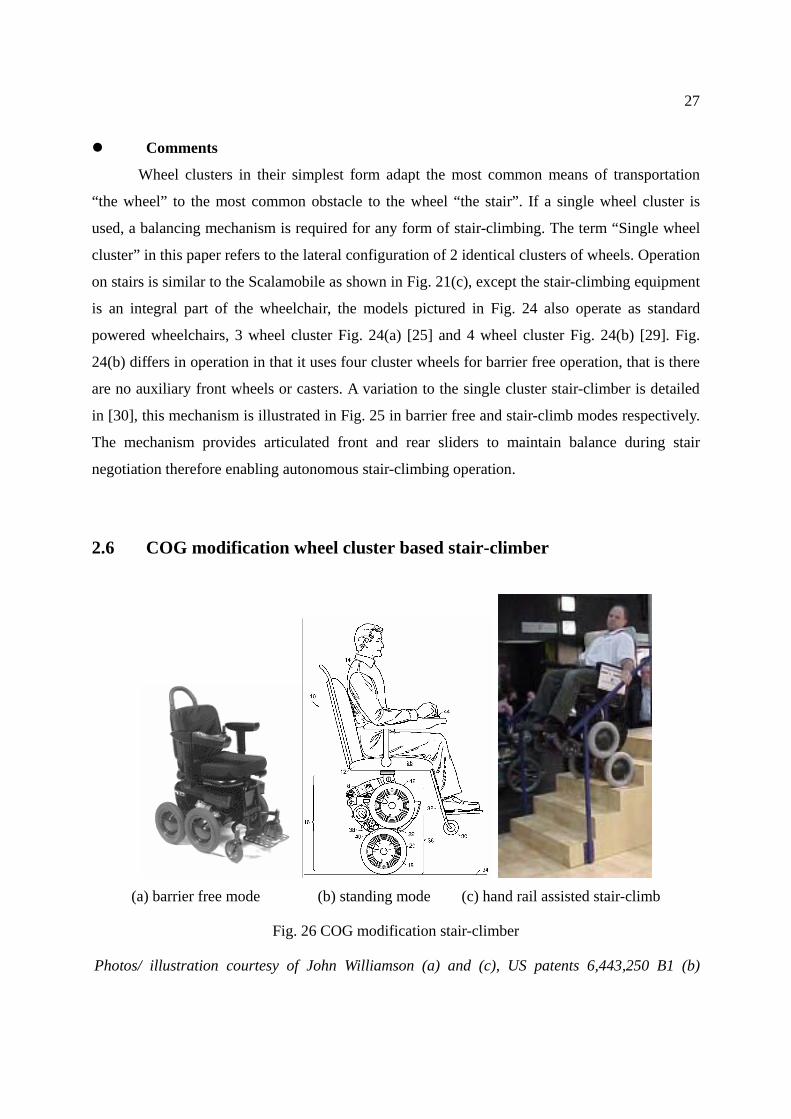
(a) barrier free mode (b) standing mode (c) hand rail assisted stair-climb
Fig. 26 COG modification stair-climber
Photos/ illustration courtesy of John Williamson (a) and (c), US patents 6,443,250 B1 (b)
Page 31
28
Features
- Stair-climbing ability suitable to almost all stairs
- Autonomous stair-climbing operation possible
- Standing mode provided for eye level communication with standing persons and
access to top shelves
- Compact (cf. track based mechanism)
- Operates as a general purpose powered wheelchair
- Operates in almost all environments including sand, gravel, highly irregular surfaces
and slopes up to ~25° (surface permitting) in the direction of desired travel
- Lightweight (cf. track based wheelchairs)
Negative points
- Requires assistance (one person) or appropriate hand rail/s for stair operation
- Must climb stairs backwards
- Expensive ($29,000 US as at Nov 21 2002)
- May be require prescription and special training (US FDA recommendation)
- Orbital stair-climbing operation may be uncomfortable for passengers
- Concern regarding balancing mechanism
Comments
In the case of a wheelchair with CM (COG modification) an appropriately located
hand-rail can be used by the operator (user) to provide commands for the balancing mechanism,
alternatively operation by and assistant similarly to that shown in Fig. 21(c). Fig. 26(a) shows the
iBOT™ 3000 wheelchair [31] [32] in barrier free mode, only the rear wheels make contact with
the ground using the front casters to provide free wheeled steering. All four rear wheels are used
to provide extra traction 4WD making operation on sand, gravel or unleveled surfaces possible. A
standing mode illustrated in Fig. 26(b) is provided, by balancing on two wheels eye to eye
contact with standing persons is possible as well as the reaching of upper shelves. Fig. 26(c)
shows the stair-climbing operation, if a handrail is appropriately provided the user can negotiate
the stairs unassisted. In the case of appropriate handrails not being available an assistant (person)
is required. Autonomous operation on stairs using a single handrail is also possible.
Page 32
29
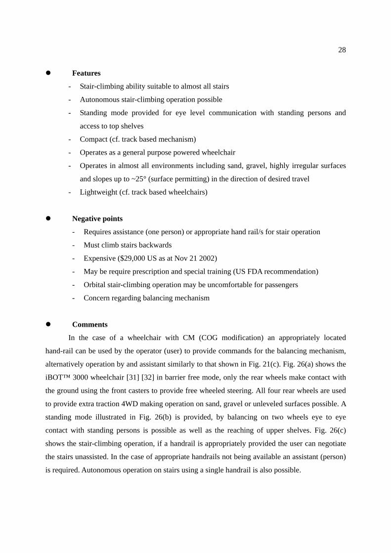
2.7 Dual wheel cluster stair-climber
(a) barrier free mode (b) stair-climbing mode
Fig. 27 Dual cluster – front articulated stair-climber, “Freedom”
Photos courtesy of Tomo Co. Ltd and Tamagawa University
Features
- Stair-climbing ability suitable to most standard stairs
- Autonomous stair-climbing operation possible
- Operates as a general purpose powered wheelchair
Negative points
- Must climb stairs backwards
- Orbital stair-climbing operation may be uncomfortable for passengers
- Large (width 820mm cf. standard powered wheelchair)
- Heavy (100Kg cf. standard powered wheelchair)
Comments
A dual cluster – front articulated stair-climber, “Freedom” is shown in Fig. 27 [33]. This
wheelchair operates as a standard powered wheelchair when configured as shown in Fig. 27(a),
Page 33
30
using the rear wheels for drive and front freewheeling casters. The configuration is changed as
shown in Fig. 27(b) for stair-negotiation. Stair-climbing is forward down and back up. The front
cluster rotates passively during stair-negotiation.
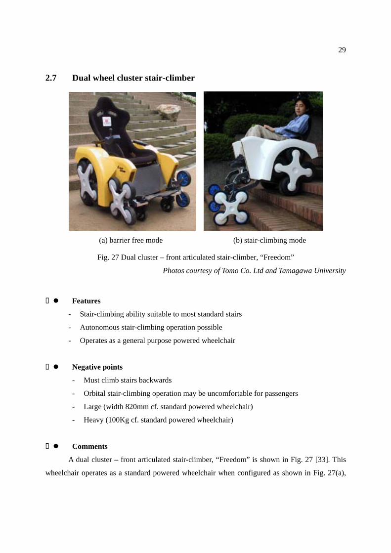
2.8 Miscellaneous stair-assist and van entry mechanisms
(a) Overhead wheelchair hoist (b) Portable wheelchair lifter (c) Seat lift/ wheelchair
Fig. 28 Miscellaneous assistive mechanisms for stairs and van entry
Photos courtesy of Outa Co. Japan (a) Toyota (b) and (c)
Features
- Stair-climbing ability suitable to most standard stairs (overhead wheelchair hoist [34])
- Van access for most wheelchairs and passenger possible (portable wheelchair lifter
and seat lift/ wheelchair [35])
- Van provided with built in dedicated seat/ wheelchair lifter (seat lift/ wheelchair)
- Van seat operates as a general purpose operator assisted wheelchair (seat lift/
wheelchair)
- Wheelchair lifter is lightweight and portable (portable wheelchair lifter)
Page 34
31
Negative points
- Expensive and dedicated to a single set of stairs (overhead wheelchair hoist)
- Lifting of standard manually propelled wheelchair not supported (seat lift/
wheelchair)
- Powered wheelchairs not supported (portable wheelchair lifter)
Comments
The provision of a seat which swivels out has become an option made available by most
Japanese car manufactures, however the task of transfer to such as a wheelchair remains. One
solution to this problem has been the provision of a seat which doubles as an assistant operated
wheelchair shown in Fig. 28(c) [35].
2.9 Recent advances in mobility assistive devices for stairs or
curbs, summary and discussion
Table 1 provides a broad categorization of curb or stair assist mobility enhancement
devices available at the time of writing.
Stair-climbing wheelchairs rated as highest risk devices
Stair-climbing wheelchairs are currently rated as highest risk devices “Class III”
alongside such as pacemakers (USA FDA.). Class III are defined generally as “life sustaining or
life supporting, implanted in the body, or present an unreasonable risk of illness or injury.”
Furthermore the functionality they provide (stair-negotiation) is not considered necessary, rather
such functionality is considered as “luxury.” In light of such attitudes at government levels (UK,
USA. etc.) the progress in regard to stair-climbing mobility has been/ is understandably slow.
Change to and from stair-angles
In regard to autonomous stair climbing vehicles the phases requiring greatest care are the
entering or exiting of a stair climb at the top of a set of stairs. This usually requires the careful
synchronizing of the mechanism’s change of angle and change of angle of the chair base in a
Page 35
32
controlled manner. That is, to avoid a sudden and uncontrolled tilt from a level angle to the stair
angle (typically 35°) or visa versa.
Table 1 Broad categorization of curb or stair assist mobility assistance devices
Device Advantages Disadvantages Curb assistive mechanism for wheelchairs Fig. 16.
Higher curbs possible, retrofitable, low cost, lightweight.
More turning space required, not compatible with all wheelchairs.
Curb capable powered wheelchairs and mobility scooters Fig. 17.
Excellent overall mobility in most environments including curb negotiation.
Additional weight makes assistance with stairs difficult, special provision required for entry to such as a van.
Track based stair climbers Fig. 19
Simple autonomous operation on stairs and/ or steep slopes possible. Operation as a standard wheelchair to some extent possible.
Only suits stairs with robust edges, typically not well suited to general purpose operation. Heavy, special provision required for entry to such as a van. Must negotiate stairs backwards.
Lightweight wheelchair stair-climbing attachments Fig. 21 and Fig. 23
Stair-climbing possible on most stairs with only one assistant, compact, lightweight.
Special training for assistant may be required. Orbital motion tends to passenger discomfort.
Wheel cluster based stair-climbers Fig. 24
Stair-climbing possible on most stairs with only one assistant, relatively compact. Operation similar to standard powered wheelchair possible.
Orbital motion may cause passenger discomfort. Special provision required for entry to such as a van.
COG modification wheel cluster based stair-climber Fig. 26
Excellent overall mobility in most environments including on sand, gravel and stairs with little or no assistance.
Concern regarding balancing mechanism. Special provision required for entry to such as a van. Must negotiate stairs backwards.
Dual wheel cluster stair-climber Fig. 27
Autonomous stair-climbing possible. Operation as a standard wheelchair to some extent possible.
Heavy, wide, special provision required for entry to such as a van. Must negotiate stairs backwards.
Misc. overhead wheelchair hoist Fig. 28(a)
Suitable to most stairs. Suitable to most wheelchairs.
Expensive, dedicated to a single set of stairs.
Misc. portable wheelchair lifter Fig. 28(b)
Van access for most lightweight wheelchairs and passenger. Portable, lightweight, low cost.
Powered wheelchairs not supported.
Misc. seat lift/ wheelchair Fig. 28(c)
Van access for dedicated seat/ wheelchair and passenger.
Transfer required if a manually propelled wheelchair is used.
This controlled tilt function is provided by the assistant in the case of single assistant
mechanisms. However in the case of the single assistant mechanisms outlined in this section the
maintenance of a constant seat angle is not possible. The seat angle is determined by the centred COG,
Page 36
33
that is, in the case of a single wheel cluster based mechanism the assistant must constantly alter the
wheelchair angle to counter the shifting COG. The provision of a mechanism to counter this COG
shift, as well counter the orbital motion inherent would be desirable for both passenger comfort and
safety. Some of the wheel cluster based mechanisms use solid rubber tyres, as noted in the previous
section they tend to be less comfortable for the passenger and are prone to breaking (Scalamobile).
The choice of solid rubber tires is assumed to reduce the size of the mechanism as well as increasing
stability.
Scalamobile in Nagasaki
The Scalamobile (Section 2.4) has been used in Nagasaki for some years but noted to be
quite uncomfortable for the person being carried and difficult to use. Special training is required
for operators. Specific problems encountered on the slopes of Nagasaki were the automatic brake
shown in Fig. 22(e) automatically locks the wheels when it drops over the front of a stair,
however on roughly hewn or cast concrete stairs the brake often cuts in during use making
operation very awkward. The inherent operator difficulty is partially being able to time the
wheelchair to arrive at the edge of the stair for the next cycle illustrated in Fig. 22(a)-(d), and
partially the inherent COG shift that occurs during the stepping cycle. The discomfort in being
carried is the inherent oscillation that occurs on account of the orbital motion produced from the
mechanism during stair climb. It must however be noted the orbital or stair-climbing speed is
adjustable, therefore operating at a slower does reduce this. As with many such devices operator
skill is central in providing user comfort.
COG modified wheel cluster based stair-climber
The iBOT™ 3000 perhaps represents the most advanced all purpose stair-climbing
mechanism at the time of writing. US government approval gained Nov 21 2002, FDA advisors
urged a few limitations namely to ensure patients can use the complex technology safely, a
doctor's prescription and special training to operate it [36].
Regarding the choice of mobility assistive solutions
In regard to the overall issue of mobility assistive devices typically a range of options are
available for any given disability, that is there is significant overlap. The choice of “best fit” will
be influenced to some degree by the perceived social acceptability in any given culture at any
Page 37
34
given time. Further preference may be influenced by personal experience, for example negative
experiences or impressions of people who used this or that mobility assistance device [37]. It is
largely the role of the “occupational therapist” (OT) to discern which device and or approach is
best suited to any given individual. The decision must also by necessity reflect the longer term
direction in which the disability is moving, whether the condition is expected to improve, be
stable or degenerative.
Summary
This section outlined recent advances in mobility assistive devices for stairs assist and
high step mechanisms available at the time of writing. A number of functions are not provided by
any mechanisms to date. The highest curb or single step negotiable is 150mm, however entrance
to a van or to a traditional Japanese home represent high single steps ranging up to about 75cm in
height. Further all stairs climbing mechanisms ascend stairs in reverse. Clearly operating a
vehicle in the direction of desired travel represents a more logical mode of operation. A solution
to these and other problems is proposed in the following section “Proposed high step and
stair-climbing mechanism.”
Page 38
35
Chapter 3 Proposed high step and stair-climbing mechanism
3.1 Introduction
The previous chapter outlined curb or stair capable mechanisms available at the time of
writing. However for mobility in the real world significant gaps remains between the
functionality required for autonomous mobility and the functionality provided by currently
available mobility devices.
This chapter focuses on the proposal of a mechanism optimized for wheelchair use and
targeted at overcoming a number of shortcomings in wheelchairs with regard to operation in
barrier present environments - refer to chapters 1 and 2. Specifically the high single step
functionality necessary to directly board such as a van or entry to a Japanese home with no
special equipment.
At the time of writing no mobility assistive device facilitates the direct boarding of a van
or access to such as a traditional home (high initial step) without the aid of special equipment
and/ or assistance. Furthermore no mobility assistive device facilitates the negotiation of stairs in
the desired direction of travel which represents a logical mode of operation.
3.2 Proposed mechanism
The proposed mechanism’s operation in barrier free environments, that is relatively flat
areas, is based on the use of 4 wheels much the same as a standard powered wheelchair. The rear
wheels are independently powered and the front wheels are free-wheeling casters. By
independently controlling the rear wheels steering is achieved.
However in order to negotiate stairs and high steps such as entrance to a vehicle or to a
Japanese home additional mechanisms are provided. The rear wheels used in barrier free mode
are 2 wheels of a 4 wheel cluster of wheels. By rotating the wheel cluster stairs can be negotiated,
refer to Section 2.4 regarding cluster based operation. The front wheels used in barrier free mode
are not used for stair climbing, rather a front cluster of 4 wheels take over from the front
free-wheeling wheels to provide the front of the mechanism with stair negotiating ability. Finally
Page 39
36
both front and rear wheel clusters are connected to the chair base via two controlled linkages so
as to permit the wheel clusters to be able to negotiate stairs and ensure the chair base angle
remains constant.
The mechanism configured for barrier free operation is illustrated in Fig. 29(a),
stair-climbing operation is illustrated in Fig. 29(b). Operation in barrier free areas is proposed to
be identical to that of a standard powered wheelchair, however by necessity in the negotiation of
obstacles such as stairs some low level assistance is required, for example the selection of mode
of operation such as: vehicle alight, vehicle disembark, stair negotiate, additional traction or
simply “stand” (high shelf or eye level contact with a standing person).
Rise = 18 cmTread = 26 cmAngle = 34.7o
(a) side elevation barrier free mode (b) side elevation stair climb mode
Fig. 29 The high step stair-climbing mechanism
3.3 Modeling process
The modeling process consists of two major parts, that is Numerical modeling to confirm
geometric feasibility particularly regarding the leg actuators, and the building of a scale model to
confirm three dimensional practicality and to some degree understand the controllability. Detail
Page 40
37
regarding the scale model is provided in Appendix B.
3.3.1 Numerical model
Numerical modeling begins with proposal of a target specification. This is followed by the
specification of geometric parameters that meet the target specifications. An analysis is provided
regarding the linear leg actuators and finally an analysis of stability margins is provided. Target
specifications for the high step stair-climbing mechanism are listed in Table 2.
Table 2 High step stair-climbing mechanism target specifications
Item Specification
Maximum continuous stair-climb angle Maximum step height Minimum step tread
35° standard (45° - max*1) 200mm 200mm
High single step 750mm*2
Maximum slope angle 25°*3
Stair-climb speed (max.) 20 steps per minute (1 step/ 3 sec.) *4
Stair descent speed (max.) 20 steps per minute (1 step/ 3 sec.) *4
Speed on the flat (max) 8 km/h
Operating range (time) Barrier free operation
Stair operation
140 minutes continuous operation 50 minutes continuous operation
Size length, width, height 1,150*5x550x900mm Seat height
Barrier free operation Stand mode (max)
450mm
1,250mm*6 Power source (battery) 12V 35Ah x2
Drive motors (primary drive) 24VDC 208W x2
Vehicle plus battery weight 130Kg + 30Kg = 160Kg
Max. passenger weight 80Kg *1 Any angle over 35° will be reflected in the seat angle, that is the seat angle is normally
set at a -6° (backward) lean, a stair angle of say 38° will alter this lean angle to -9° for ascent and -3° for descent and in worst case a 45° stair would result in a -16° (backward) lean for ascent and +4° (forward) lean for descent.
*2 High single step 750mm, in the case of a high single step the landing must provide at
Page 41
38
least 1,000mm of landing space. In the case of the high step including a regular final step as is the case in many Japanese entrances the final step must not exceed 200mm in height or 450mm in depth refer to Fig. 51.
*3 Under ideal tractive conditions, derating required in case of wet and/ or slippery conditions. Seat angle remains constant, assumes use of barrier present mode.
*4 Assumes synchronous operation, refer Sections 3.4 and 3.5. *5 Vehicle length assumes footplates are folded down, this reduces to 1,000mm when the
foot plates are folded up. *6 Level surface assumed for maximum standing height.
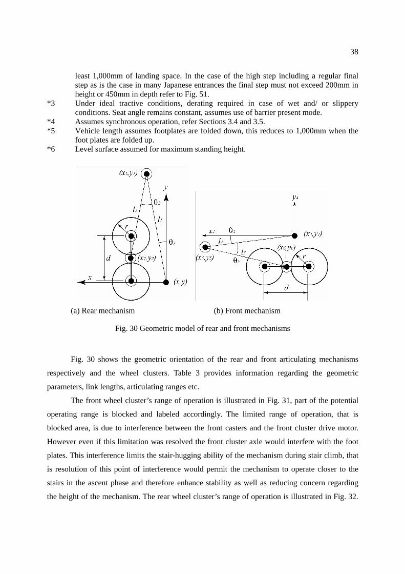
(a) Rear mechanism (b) Front mechanism
Fig. 30 Geometric model of rear and front mechanisms
Fig. 30 shows the geometric orientation of the rear and front articulating mechanisms
respectively and the wheel clusters. Table 3 provides information regarding the geometric
parameters, link lengths, articulating ranges etc.
The front wheel cluster’s range of operation is illustrated in Fig. 31, part of the potential
operating range is blocked and labeled accordingly. The limited range of operation, that is
blocked area, is due to interference between the front casters and the front cluster drive motor.
However even if this limitation was resolved the front cluster axle would interfere with the foot
plates. This interference limits the stair-hugging ability of the mechanism during stair climb, that
is resolution of this point of interference would permit the mechanism to operate closer to the
stairs in the ascent phase and therefore enhance stability as well as reducing concern regarding
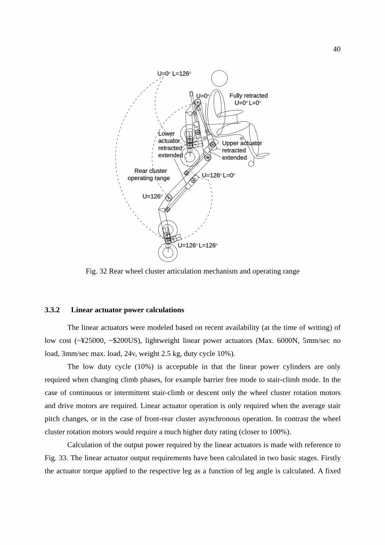
the height of the mechanism. The rear wheel cluster’s range of operation is illustrated in Fig. 32.
Page 42
39
Actuated leg range angles are indicated based on 0° when fully retracted (folded up).
Table 3 High step stair-climbing mechanism geometric parameters
Description Notation Measure Operating range (angle) Offset (angle)
Wheel radius r 12.5cm
Cluster spacing d 30cm
Rear leg upper link 1l 74.5cm 126° 10° (U=0°)
Rear leg lower link 2l 58.4cm 126° 22° (L=0°)
Front leg upper link 4l 62.4cm 76° 96.5° (U=0°)
Front leg lower link 5l 57.7cm 70° 21° (L=0°)
Front to rear Reference
( )yx, rear ( )44, yx front 52.2cm (assumes chair @ -6°
angle, on level surface) 61°
Upper actuator retracted extended
Lower actuatorretractedextended
U=0o
U=76oU=0o L=70o
U=76o L=70o
Fully retracted U=0o L=0o
Front clusteroperating range
Blocked area
Fig. 31 Front wheel cluster articulation mechanism and operating range
Page 43
40
Upper actuatorUpper actuatorretractedretractedextendedextended
LowerLoweractuatoractuatorretractedretractedextendedextended
U=126U=126o
U=0U=0o
U=126U=126o L=0L=0o
U=126U=126o L=126L=126o
U=0U=0o L=126L=126o
Rear cluster Rear clusteroperating rangeoperating range
Fully retractedFully retracted U=0 U=0o L=0L=0o
Fig. 32 Rear wheel cluster articulation mechanism and operating range
3.3.2 Linear actuator power calculations
The linear actuators were modeled based on recent availability (at the time of writing) of
low cost (~¥25000, ~$200US), lightweight linear power actuators (Max. 6000N, 5mm/sec no
load, 3mm/sec max. load, 24v, weight 2.5 kg, duty cycle 10%).
The low duty cycle (10%) is acceptable in that the linear power cylinders are only
required when changing climb phases, for example barrier free mode to stair-climb mode. In the
case of continuous or intermittent stair-climb or descent only the wheel cluster rotation motors
and drive motors are required. Linear actuator operation is only required when the average stair
pitch changes, or in the case of front-rear cluster asynchronous operation. In contrast the wheel
cluster rotation motors would require a much higher duty rating (closer to 100%).
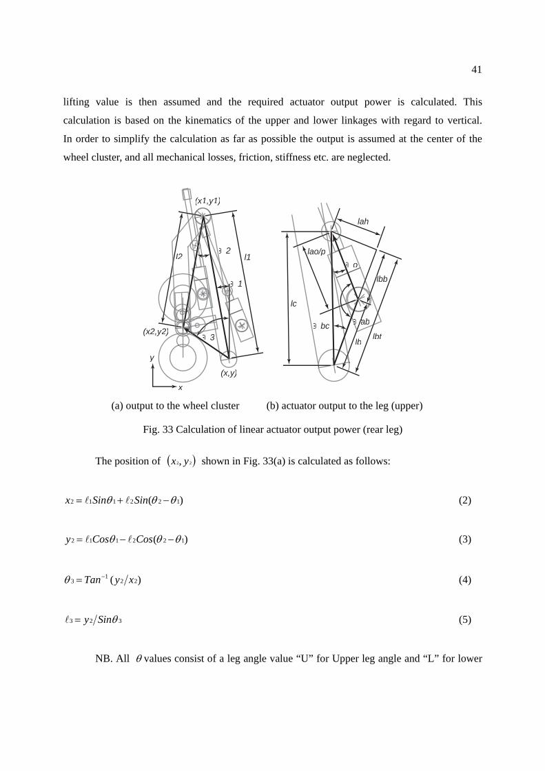
Calculation of the output power required by the linear actuators is made with reference to
Fig. 33. The linear actuator output requirements have been calculated in two basic stages. Firstly
the actuator torque applied to the respective leg as a function of leg angle is calculated. A fixed
Page 44
41
lifting value is then assumed and the required actuator output power is calculated. This
calculation is based on the kinematics of the upper and lower linkages with regard to vertical.
In order to simplify the calculation as far as possible the output is assumed at the center of the
wheel cluster, and all mechanical losses, friction, stiffness etc. are neglected.
Θbc
ΘΘo
ΘΘΘaba
llbblb
lblb lbtlb
lah
lao/p
lc
Θ2l1l2
Θ1
Θ3
(x,y)
(x1,y1)
(x2,y2y2)2)
x
y
(a) output to the wheel cluster (b) actuator output to the leg (upper)
Fig. 33 Calculation of linear actuator output power (rear leg)
The position of ( )22, yx shown in Fig. 33(a) is calculated as follows:
)( 122112 θθθ −+= SinSinx ll (2)
)( 122112 θθθ −−= CosCosy ll (3)
)( 221
3 xyTan−=θ (4)
323 θSiny=l (5)
NB. All θ values consist of a leg angle value “U” for Upper leg angle and “L” for lower
Page 45
42
leg value and an offset component which relates the leg angle to a vertical reference in the case of
the upper leg and to alignment with the upper leg in the case of the lower leg. Offset values and
lengths relating to equations (2)-(5) are as follows:
1θ offset value °10 at U= °0
2θ offset value °22 at L= °0
1l length 74.5cm
2l length 58.4cm
The output torque applied in this case to the rear leg (upper) can be related to actuator
output illustrated in Fig. 33(b), and can be calculated as follows:
bccah Sinθll = (6)
bccbt Cosθll = (7)
bbtbb lll −= (8)
The actuator output position pao /l is thus given by
22/ ahbbpao lll += (9)
)(180 /1
paobbab Cos ll−−=θ (10)
The actuator’s angle of incidence 0θ to the leg is given by
abbc θθθ −−=1800 (11)
The torque at ( )11, yx denoted ),( 11 yxT can be calculated from
Page 46
43
01
0),( 11 θSinPT cyxl
l= (12)
where 0P is the actuator’s mechanical output power (kgf/cm). The resultant lifting
capability to the wheel cluster center can be expressed as
330
0 θθ
CosSinPP c
liftl
l= (13)
where liftP represents the resultant vertical lift component at the wheel cluster center. As
the lift component is fixed in this case 80Kg (refer to following Section on stability margins) the
expression is rearranged to give the required actuator output power for any given configuration of
the legs. This is expressed as
033
0 θθ
SinCosPP
clift
ll= (14)
In applying this to the lower actuator the expression is altered to
0
1220
)(θ
θθSin
CosPPc
liftl
l −= (15)
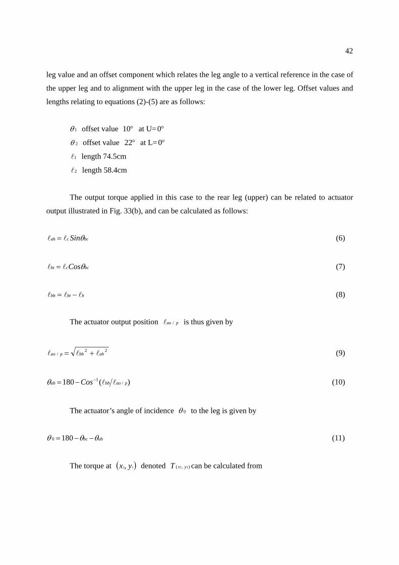
where cl and 0θ refer to the lower actuator’s parameters. Fig. 34 shows the calculated
actuator output requirements for each actuator. This data is based on the front and rear wheel
clusters following a near linear trajectory from a barrier free orientation to the rear leg orientation
shown in Fig. 38 and front leg orientation shown in Fig. 43. The leg angle data was measured
from a calibrated 2D paper model and then calculations made as per formulae (2) to (15).
The kinematical orientation of each actuator was optimized based on five main
constraints. Firstly a peak output of 600 kgf/cm (~6000N) was assumed. Secondly, the overall
size of the wheelchair must not exceed that of a standard powered wheelchair. The seat height (in
barrier free mode) must match that provided by a standard wheelchair (~45cm). The front and
rear leg operating envelopes must facilitate negotiating a °35 set of stairs forward up and
forward down with no change in chair angle and finally be able to negotiate a single step e.g.
Page 47
44
vehicle entry of up to 75cm (forward up - back out).
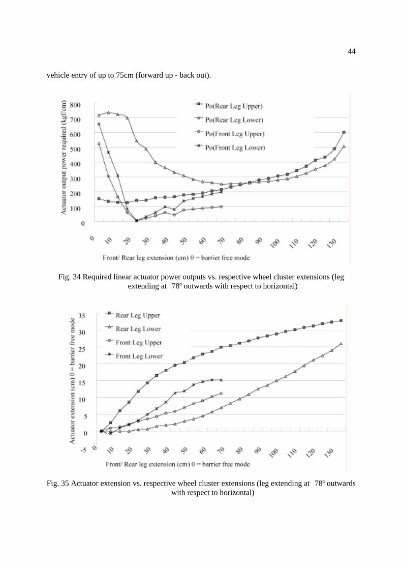
Fig. 34 Required linear actuator power outputs vs. respective wheel cluster extensions (leg extending at °78 outwards with respect to horizontal)
Fig. 35 Actuator extension vs. respective wheel cluster extensions (leg extending at °78 outwards with respect to horizontal)
Page 48
45
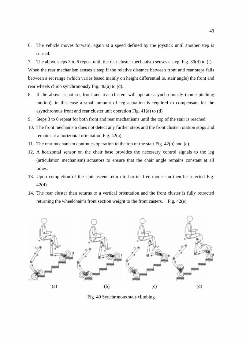
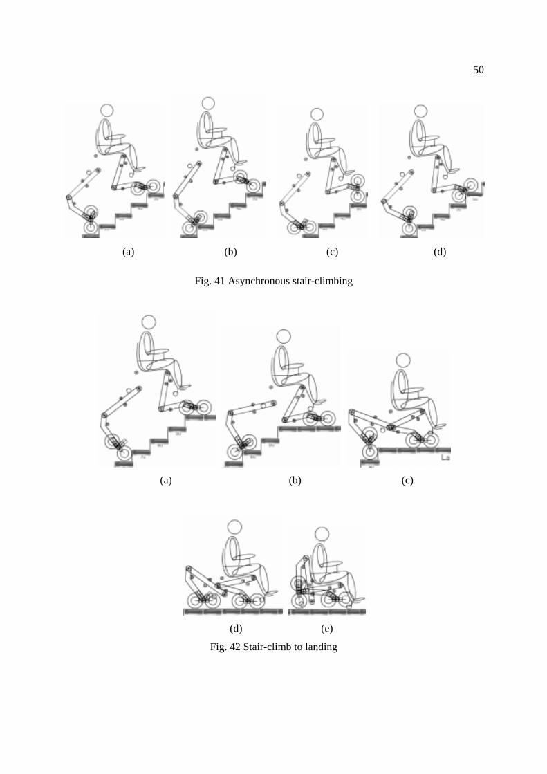
With reference to Fig. 34 the peak output appears to be exceeded at 2 points. Firstly the
rear leg lower actuator exceeds the 600kgf/cm for the first 20cms of operation, however with
reference to Fig. 35 which shows “actuator extension,” operation is not required during this phase.
In the case of the front leg upper cylinder the first 5cm of operation simply lowers the front wheel
cluster to the ground in order to take over from the free wheeling casters, therefore no output
power is required during this phase. Peak outputs only occur during the first few seconds of
reconfiguration from barrier free mode and at maximum reach in the case of the rear mechanism.
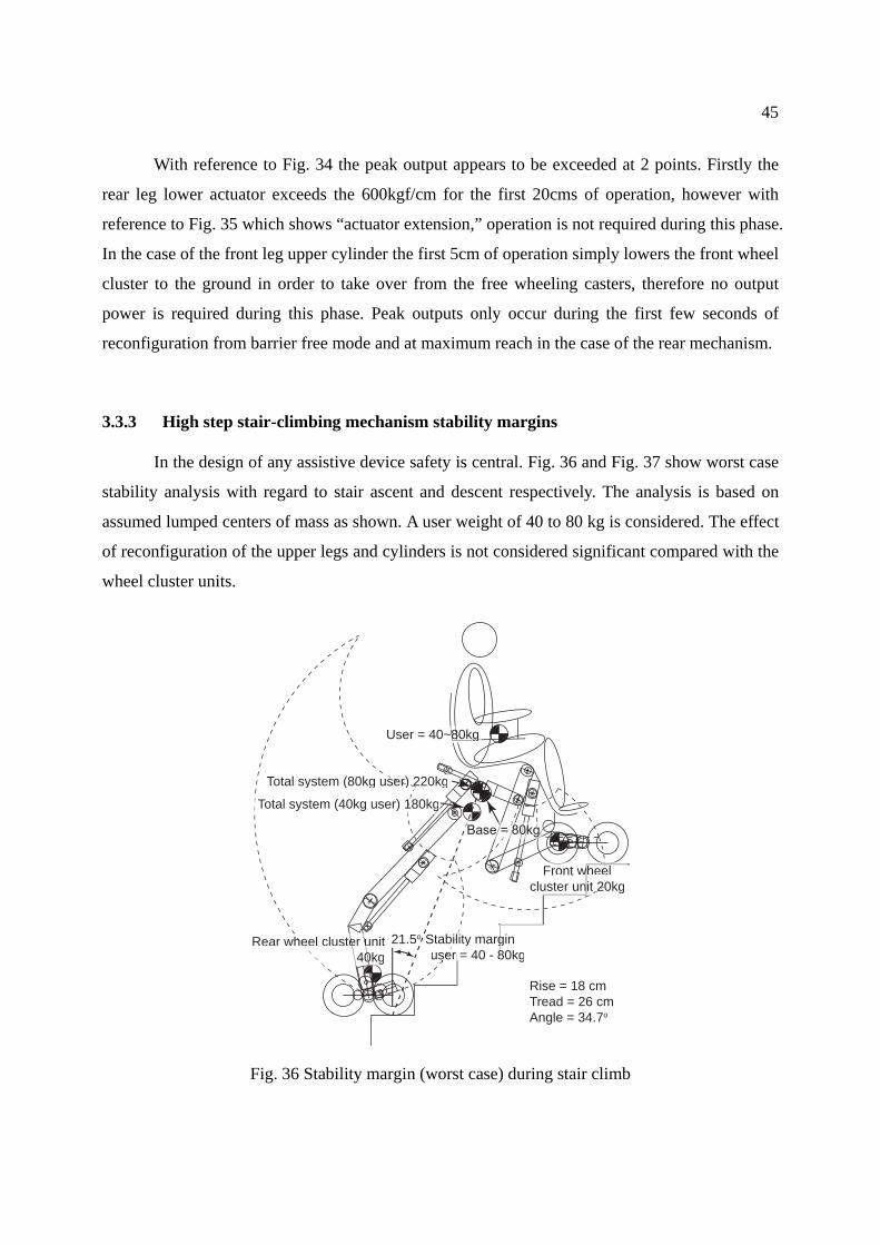
3.3.3 High step stair-climbing mechanism stability margins
In the design of any assistive device safety is central. Fig. 36 and Fig. 37 show worst case
stability analysis with regard to stair ascent and descent respectively. The analysis is based on
assumed lumped centers of mass as shown. A user weight of 40 to 80 kg is considered. The effect
of reconfiguration of the upper legs and cylinders is not considered significant compared with the
wheel cluster units.
Rise = 18 cmTread = 26 cmAngle = 34.7o
21.5o Staability marginbil g user = 40 - 80kgser = 40 - 80kgse = 40 - 88
heeleFront wwit 20kg0cluster un t 20
Rear wheel cluster uniter uhe40kg0
User = 40~80kg88 g
Total system (80kg user) 220kgser) 2
Total system (40kg user) 180kgg1
Fig. 36 Stability margin (worst case) during stair climb
Page 49
46
Each linear cylinder ~2.5kg in weight moves over a range of less than 10% compared
with the wheel clusters and are therefore lumped together with the base. The chair base weight
consists mainly of 2x15kg (representative) standard powered wheelchair batteries which are
located in diagonal opposition, one under the front of the right hand side of the chair and the
other to the rear on the left hand side (referenced to the user’s orientation).
In the case of the stair climb the user’s COG (center of gravity) is aligned with that of the
overall system COG, and therefore stability is constant irrespective of the user’s weight. Stability
during the descent phase is more complex, in order to maximize the stability and minimize any
potential user concern regarding the slightly impeded view of terra firma (inability to see in front
of the wheelchair), it is essential to keep the chair base as low as possible. The main constraint in
this regard is clearance between the front leg central joint and the stairs, as seen in Fig. 37.
Rise = 18 cmTread = 26 cmAngle = 34.7o
User = 40~80kgs
Front wheeleeFrront whecluster unit 20kg
Total system (80kg user) 220kgk20Total system (40kg user) 180kge
Rear wheel cluster unitc un40kg40k
Stability margins21.5o user = 40kg19o user = 80kg
Base = 80kgaseBasas = 8e
Fig. 37 Stability margin (worst case) during stair descent
During the descent phase the user’s COG is not aligned with that of the overall system
and the stability margin reduces from 21.5o for a 40kg user to 19 o for an 80kg user. The stability
Page 50
47
margins involved in vehicle boarding are less critical than stair negotiation, as can be seen in Fig.
48. The location of the wheel clusters, particularly the rear wheel cluster can be altered freely
(within the operating envelopes) to facilitate a stability margin of >25 o for the maximum high
step operation (75cm).
The wheelchair control system clearly must monitor the stability margins at all times
during barrier present operation, in the case of stair negotiation one parameter cannot easily be
ascertained, that is which wheel pair is the load bearing pair at any given time. Knowledge of
such however is not necessary if the innermost pair (wrt. the chair base) are assumed to be load
bearing thus giving the worst case stability margins. The above stability margins are static only
considerations, and assume the wheel cluster rotation acceleration is not significant. With regard
to the user’s position (COG) in the case of stair-climbing, the user is not liable to relocate
themselves to the rear of the chair, however in the descent condition the user’s repositioning their
weight to the front edge of the chair could negatively impact the stability margin.
3.4 Stair ascent
Rise = 18 cmTread = 26 cmAngle = 34.7o
Fig. 38 Stair-climb operation ascent
Page 51
48
Stair ascent is illustrated in Fig. 38. Stair ascent is achieved as follows:
1. User indicates “stair-negotiate”
2. The chair is raised sufficiently to permit front mechanism stepping, step and step edge
sensors are proposed – detailed in Section 3.7.2. One sensor system to detect a step,
indicating need for stair ascent Fig. 39(a) to (c), and another to detect having crossed over the
edge of a step, indicating stair descend Fig. 44(a) to (c).
3. The chair continues to rise in a level manner until sufficient height is available to negotiate
the next step.
4. The front cluster will rotate up or down at a speed defined by the user (ie. forward or
backward on the joystick).
5. The wheel cluster rotation stops when the wheel cluster returns to a horizontal disposition.
(a) (b) (c)
(d) (e) (f)
Fig. 39 Entrance to a stair climb
Page 52
49
6. The vehicle moves forward, again at a speed defined by the joystick until another step is
sensed.
7. The above steps 3 to 6 repeat until the rear cluster mechanism senses a step. Fig. 39(d) to (f).
When the rear mechanism senses a step if the relative distance between front and rear steps falls
between a set range (which varies based mainly on height differential ie. stair angle) the front and
rear wheels climb synchronously Fig. 40(a) to (d).
8. If the above is not so, front and rear clusters will operate asynchronously (some pitching
motion), in this case a small amount of leg actuation is required to compensate for the
asynchronous front and rear cluster unit operation Fig. 41(a) to (d).
9. Steps 3 to 6 repeat for both front and rear mechanisms until the top of the stair is reached.
10. The front mechanism does not detect any further steps and the front cluster rotation stops and
remains at a horizontal orientation Fig. 42(a).
11. The rear mechanism continues operation to the top of the stair Fig. 42(b) and (c).
12. A horizontal sensor on the chair base provides the necessary control signals to the leg
(articulation mechanism) actuators to ensure that the chair angle remains constant at all
times.
13. Upon completion of the stair ascent return to barrier free mode can then be selected Fig.
42(d).
14. The rear cluster then returns to a vertical orientation and the front cluster is fully retracted
returning the wheelchair’s front section weight to the front casters. Fig. 42(e).
(a) (b) (c) (d)
Fig. 40 Synchronous stair-climbing
Page 53
50
(a) (b) (c) (d)
Fig. 41 Asynchronous stair-climbing
(a) (b) (c)
(d) (e)
Fig. 42 Stair-climb to landing
Page 54
51
During the stair climb the front cluster acts as the master in terms of defining the base
(chair) to stair height/ clearance, the chair level is automatically maintained at a -6 o camber. Fig.
38 and Fig. 40 shows the mechanism during stair-climbing operation, in the case of synchronous
front and rear cluster operation. Asynchronous stair-climbing is shown in Fig. 41. A means of
estimating and controlling the front to rear cluster distance is required when asynchronous
operation occurs. In the case of synchronous stair-climbing the cluster to cluster spacing simply
remains fixed throughout the stair-climbing operation.
For operation on slopes the user would be provided with the option of standard barrier
free mode or high traction mode Fig. 42(d). In the case of barrier free mode correction of the
chair angle cannot be provided for, this automatic correction only becomes possible in
stair-climbing or high traction mode. It is therefore envisaged that in the case of negotiating stairs
interleaved with slopes as shown in Fig. 63(b) barrier free mode would only be selected once off
the slopes and stairs.
3.5 Stair descent
Stair descent is illustrated in Fig. 43. Stair descent is achieved as follows:
1. User indicates “stair-negotiate”
2. The chair is raised sufficiently to permit front mechanism stepping, step and step edge
sensors are proposed – detailed in Section 3.7.2. One sensor system to detect a step,
indicating need for stair ascent Fig. 39(a) to (c), and another to detect having crossed over the
edge of a step, indicating stair descend Fig. 44(a) to (c).
3. The chair continues to rise in a level manner until sufficient height is available to negotiate
the next step Fig. 44(c).
4. The front cluster will rotate down at a speed defined by the user (ie. forward on the joystick).
5. The wheel cluster rotation stops when the wheel cluster returns to a horizontal disposition.
6. The vehicle moves forward, again at a speed defined by the joystick until another step is
sensed.
7. The above steps 3 to 6 repeat until the rear cluster mechanism senses a step Fig. 44(f).
When the rear mechanism senses a step if the relative distance between front and rear steps falls
Page 55
52
between a set range (which varies based mainly on height differential ie. stair angle) the front and
rear wheels descend synchronously. Fig. 45(a) to (d).
Rise = 18 cmTread = 26 cmAngle = 34.7o
Fig. 43 Stair-climb operation descent
8. If the above is not so, front and rear clusters will operate asynchronously (some pitching
motion), in this case a small amount of leg actuation is required to compensate for the
asynchronous front and rear cluster unit operation Fig. 46(a) to (d).
9. Steps 3 to 6 repeat for both front and rear mechanisms until the bottom of the stair is reached.
The front mechanism does not detect any further steps and front cluster rotation stops and
remains at a horizontal orientation Fig. 47(a).
10. The rear mechanism continues operation to the bottom of the stair Fig. 47(a) to (f).
11. The horizontal sensor on the chair base provides the necessary control signals to the leg
(articulation mechanism) actuators to ensure that the chair angle remains constant at all
times.
12. Upon completion of the stair descent return to barrier free mode can then be selected Fig.
47(g).
13. The rear cluster then returns to a vertical orientation and the front cluster is fully retracted
returning the wheelchair’s front section weight to the front casters Fig. 47(h).
Page 56
53
(a) (b) (c)
(d) (e) (f)
Fig. 44 Entry to stair-descent
During the stair descent the front cluster acts as the master in terms of defining the base
(chair) to stair height/ clearance, the chair level is automatically maintained at a -6 o camber. Fig.
43 and Fig. 45 show the mechanism during stair-climbing operation, in the case of synchronous
front and rear cluster operation.
The need for a means of controlling the spacing between front and wheel cluster centers is
the same as for asynchronous stair-ascent. In the stair descent phase the stair-hugging ability is
largely limited by the lower front leg’s clearance to the stair as noted in most of the stair descent
illustrations. The user’s average height above the stairs is lower in the descent phase compared to
the ascent phase, however the perceived height would be much greater on account of the line of
sight being above the stair height. The impeded view of the stairs below is liable to be a point of
initial concern.
Page 57
54
(a) (b) (c) (d)
Fig. 45 Synchronous stair-descent
(a) (b) (c) (d)
Fig. 46 Asynchronous stair-descent
(a) (b) (c) (d)
Page 58
55
(e) (f) (g) (h)
Fig. 47 Stair-descent to a landing
3.6 High-step operation
The most central feature of the high step stair-climbing mechanism is the high step
capability. At the time of writing no powered mobility assistive device (wheelchair) inherently
provides a means of boarding or disembarking from such as a van. In the case of Japan the first
step into a traditional Japanese home represents a step ranging from about 30 to 60 cm.
Vehicle boarding @ 55.5 cm Front temp.
rest point
Fig. 48 Direct van entry – front cluster boarding entry trace
Page 59
56
It is possible to provide some form of ramp or lifting mechanism for both the van and
entrance to such as a traditional home, but always at a cost and tradeoff in terms of space and in
the case of a van weight. Further, most ramp or lifting solutions are dedicated, that is lack
portability. The design of the high step mechanism was based on a maximum single step height of
75 cm.
High single step negotiation is achieved as follows (up):
1. User indicates high step (up) Fig. 50(a)
2. The chair is raised to the appropriate height under user control.
3. The chair is then moved into the position shown in Fig. 48 and Fig. 50(c).
4. An appropriate sensor is proposed to confirm the distance into the high step, that is distance
between the caster’s lagging position (irrespective of the caster’s actual direction) and the
leading edge of the high step – refer to Section 3.7.2 .
5. The front mechanism is then folded while being rotated clockwise as shown in Fig. 48 and
Fig. 50(d) in the path indicated.
6. The front wheel cluster continues to a horizontal disposition and lowered to a level a little
below the casters thus taking the main weight so as to ensure precise forward movement Fig.
50(e), this is mainly to prevent any direction changes that may occur on account of van decks
which usually are not perfect level surfaces or to account for the vehicle being parked
non-horizontally (free wheeling caster operation under these conditions tends to be erratic).
7. The chair is then moved forward, again under user control to a position ensuring the
temporary rest point shown in Fig. 49 is sufficiently inside the vehicle. A sensor is also
proposed to verify this Fig. 50(f).
8. The rear mechanism is then folded in the manner shown in Fig. 49 and Fig. 50(g). The rear
wheel cluster is rotated clockwise as shown in an arc close to the step edge (boarding deck).
The rear wheel cluster represents a significant percentage of the vehicle’s weight therefore
unnecessary swing out reduces the overall stability margin in the rearward direction.
9. The rear wheel cluster is then vertically orientated, resulting in the weight and traction being
returned to the rear wheel cluster Fig. 50(h).
10. Finally the vehicle can be relocated in the van, the wheelchair tied down appropriately and
the user’s seat belt also done up ready to go.
Page 60
57
Vehicle boarding @ 55.5 cm Rear temp.
rest point
Fig. 49 Direct van entry – rear cluster entry trace
The operation of disembarking from a van is identical to the boarding operation, however
as the operation is backwards it would be significantly more difficult for the user to confirm the
vehicle’s location in regard to the rear edge of the van and planned disembarkation area. In the
case of entry to such as a traditional Japanese home such as that shown in Fig. 51 some
parameters are a little different from entrance to such as a van. The points of variation are that
there is no space under the step edge, that is the wheels cannot be placed under as in Fig. 50(c).
Further there is often a second step of regular height immediately following the initial high step
as is the case pictured in Fig. 51, this situation would require the front casters to be relocated
twice, in this regard an “entrance to a traditional Japanese house” mode would be required. The
more general purpose solution to such situations would be to provide the vehicle with record and
playback functionality, that is negotiate the entrance with care in record mode and after that
simply recall that operation from memory.
Stability exceeds 25 o at all times during high step operation. This assumes rear cluster
swing out is not excessive during the final van boarding phase Fig. 50(g). In the case of a single
Page 61
58
high step where the front wheels cannot be placed under the step edge as is usually the case of a
Japanese entrance Fig. 51, the rear cluster can be shifted further back to ensure maintenance of a
25 o plus stability margin.
(a) (b) (c)
(d) (e) (f)
(g) (h)
Fig. 50 Boarding and disembarking from a vehicle (high step)
Page 62
59
Fig. 51 Entrance to a traditional Japanese house
3.7 Proposed control system
This section outlines a proposed control system for the high step stair-climbing
mechanism. An overall system schematic is proposed, a stair and stair edge sensor system is
proposed. A “one step at a time” stepping algorithm is proposed and explained. Finally the
control system necessary to achieve wheel cluster rotation compensation is outlined. The control
system implemented on a scale size high step stair-climbing mechanism is outlined in Appendix
B.
3.7.1 Control system
Fig. 52 shows a schematic diagram of the overall control system for the proposed high
step mechanism. Power steering is included for barrier present operation, ideally ±45° of steering
should be provided on the front wheel cluster to enable the negotiation of irregular or curving
stairways. Spiral stairways would however only be possible if the minimum tread depth of 20cm
was not exceeded.
Page 63
60
Fig. 52 Control system schematic for proposed high step stair-climbing mechanism
3.7.2 Stair and stair edge sensor system
Proposed placement of stair and high step sensors are shown in Fig. 53. One narrow beam
proximity sensor is place centrally behind the front casters, this would ensure the vehicle is
placed sufficiently inside the van upon entry, refer to Fig. 48. Similar sensors would be placed
Page 64
61
behind the rear “temporary rest points” to ensure the vehicle is sufficiently inside the van deck,
(refer to Fig. 49) during the final phase of entry. Four sets of four proximity sensors are proposed
for stair and stair edge detection. A left and right identical set of sensors is recommended to
account for negotiation angle error, that is deviation from a 90° (straight on) approach angle.
Fig. 53 Proposed stair sensor placement
Each sensor set consists of a forward facing wide angle beam proximity sensor for
detection of distance to next step, an identical rearward facing sensor providing stair distance
sense if operating in reverse. The vehicle is designed to be operated in the direction of desired
travel. However the need to reverse out of any given situation must be considered. Stair edge
detection is proposed using two narrow beam proximity sensors one just in front of the cluster
center and another just behind. The stair edge sensors would provide precise information
regarding the stair edge. This data would be combined with wheel and cluster rotation data to
model each step so as to ensure the front to rear cluster spacing is correct at all times. This is
Page 65
62
particularly important during asynchronous stair-climbing Fig. 41 and stair-descent Fig. 46. In the
case of synchronous operation on a regular set of stairs wheel cluster spacing is constant. The
vertical elevation offset component is calculated from leg angle data with reference to a front-rear
pitch angle sensor mounted on the chair base. A role angle sensor would be advisable also to
bring the vehicle to a soft stop in the case of excessive role occurring, for example if one side
missed or slipped off a step for some reason.
The fixed base vehicle boarding sensors are fixed to the chair base, the front and rear stair
and stair edge sensors however are on the lower leg sections near the wheel cluster units. In the
case of the front leg lower section it’s orientation in the vertical plain is relatively constant during
stair negotiation and therefore the sensors could be simply fixed to the lower leg unit. However in
the case of the rear leg lower section a vertical variation in the order of 45° occurs, Fig. 45(b) cf.
Fig. 46(b). To compensate for this variation a gravity based mount could be employed,
alternatively a mechanical linkage back to the chair to maintain vertical alignment.
In the case of erroneous data occurring, for example false stair or stair edge readings or
false wheel rotation data (slippage etc.), it is envisaged the vehicle would be brought to a soft
stop and confirmation sort from the user before continuing.
3.7.3 Stepping algorithm
Fig. 54 Wheel cluster trace detail
Page 66
63
Fig. 54 shows a detailed wheel cluster trace based on “rotation to level”, that is the cluster
upon sensing a step will rotate until the cluster returns to a horizontal orientation. Once level
orientation is achieved forward motion returns to user control and sensing of a next step (if
present) becomes valid.
This simple “one step at a time” algorithm assumes no regularity in the steps. In the case
of stair descent reference is made to falling edge detection. Synchronism between the front and
rear wheel clusters depends on stair spacing. The front and rear units operate independently
except that drive is provided by the rear wheels and therefore the front cluster operates as slave to
the rear cluster in regard to forward or reverse operation. In this regard when the front wheel
cluster senses a step it requires the motion shown by the “wheel cluster center trace” shown in
Fig. 54, z is the required forward motion.
The z value can be approximated (tire characteristics not accounted for) as follows:
rhdz −−= 22 (16)
with reference to Fig. 54. The representative modeled parameters were as follows:
d distance between wheel axles on the wheel cluster = 31cm
h step rise = 18cm
r wheel radius = 12.5cm
Regarding the d value, keeping this value as small as possible provides maximum step
edge clearance and provides for optimal power transmission ability (ie. max. sprocket or gear
size) for wheel cluster unit rotation. In the case of the scaled model outlined in Appendix B the
cluster axle continued through the wheel unit as seen in Fig. 85. While this is mechanically
convenient it results in impractical stair edge clearance, making wheel cluster transmission
difficult. Ideally the cluster’s wheels should be located as close as possible eg. d =2 r + ~1cm.
In the case of step tread depth s > d +1.5 r (>49.75cm wrt above case - 1.5 r, the addition
of 0.5 providing a reasonable margin of safety) cluster rotation (~180o) is not necessary rather a
small negative rotation (~35o) will enable negotiation of the step (positive rotation referring to
rotation in the same direction of travel). However to implement this step toward greater operating
Page 67
64
efficiency the respective step depths (tread) must be ascertained, this would only be possible for
stair ascend, as in the case of descent the tread value is only known after the step has been
negotiated.
The cluster trace shown in Fig. 54 reflects the movement of the chair base in the case of
synchronous stair negotiation. Feedback from persons being transported by the Scalamobile
outlined in Section 2.3 which has a similar although not identical motion has often been of a
negative nature regarding the orbital motion. The magnitude of motion (acceleration) experienced
can be altered by changing the climb speed in the case of the Scalamobile. This compares poorly
with the inherently smoother operation of the track based counter part outlined in Section 4.
The proposed stair negotiation algorithm is shown in Fig. 55 and Fig. 56 for the case of
the front wheel cluster negotiating a step. The algorithm is based on negotiation of one step at a
time. Memory of a previous step is used to estimate the lowest chair base to stair configuration,
that is keep the chair level as low as possible at all times. The same data is also used for reference
as the rear wheels negotiate the same stairs. Fig. 55 (part 1) outlines the program flow which
determines the mechanism’s mode of operation, direction of travel and therefore configures the
legs appropriately and enters the appropriate stepping algorithm in the case of a step being
detected. Fig. 56 (part 2) outlines the negotiating of a single step by the front wheel cluster.
During the negotiation checkpoints are provided to ensure correct operation, in the case of any
sensor readings being outside given limits the mechanism is brought to a soft stop and the user
notified. The user would be advised of the exception and asked for confirmation of the situation,
whether to ignore and continue or correct anything that requires correction.
The algorithms for “operation in reverse” and “rear cluster stepping forward” vary from
the “front cluster stepping forward” algorithm in accordance with the logical availability of stair
height (rise) and depth (tread) data.
Provision of an interrupt must be available for the rear wheel cluster, so that at the instant
the rear wheels detect a step a decision can be made regarding whether or not synchronous
operation is possible. The front and rear legs are designed to extend at 78° from their retracted
configurations, however a tolerance in the order of -2° to +4°/ +6° (depending on leg configuration) is
available to align the wheel cluster centres with the stairs. This alignment is required for synchronous
operation. In the case of synchronous stair negotiation the cluster drives simply need to operate at a
constant speed relative to each other. In the case of irregular stairs this will be detected automatically
Page 68
65
and re-evaluation of whether synchronous operation can be continued would be re-considered on a
per step basis, most small irregularities would simply require a small adjustment of front to rear
cluster spacing.
Fig. 55 Stair negotiate algorithm part 1
Page 69
66
Fig. 56 Stair negotiate algorithm part 2
Page 70
67
Asynchronous stair negotiation requires the legs to be dynamically reconfigured. This
reconfiguration of the legs is necessary to change the wheel cluster centres to cater for the cluster’s
operating in different parts of the orbital phase or cluster trace (refer Fig. 54). Asynchronous
operation may result in slower stair negotiation as the cluster rotation may be limited by the leg
actuation speed. The amount of leg actuation is not great and is not expected to exceed the 10% duty
cycle rating of the leg actuators.
3.7.4 Compensation for wheel cluster rotation
While ascending or descending stairs it is assumed that the rear cluster drive wheels
remain stationary with respect to forward travel as the rear wheel cluster rotates. The
compensation necessary to achieve this is
dsedpr
cl
grgdgKK
/21
2 = (17)
where K2 is the correction required. In the case of the scaled model outlined in Appendix B, 2r (r
=12.5cm) was the represented wheel diameter, d (31cm) the distance between the wheel axles, gcl
(1/20) was the gear transmission ratio to the cluster motor, gdpr (12) and gdse (56) are the primary
and secondary gear transmission ratios to the drive motors (left and right).
Fig. 57 Drive motors and rear cluster controller schematic diagram
Page 71
68
In the case of the scale model mechanism the K2 value calculated was 0.205 for a K1 value
of 1. A simplified schematic of the drive motor and rear cluster control system is shown in Fig. 57
which illustrates the relationships between these values.
3.8 High step and stair-climbing mechanism - discussion
Extending the ability of mobility assistive devices
This chapter introduced and outlined a mechanism designed to negotiate stairs and high
steps such as entry to a van. The mechanism is optimized for use in wheelchair application.
Chapter 2 provided an overview of “prior art,” that is mobility assistive mechanisms available at
the time of writing. The purpose of assistive mechanisms is to “assist” persons toward being
more mobile and usually toward increasing any given users’ level of autonomy. The point of
reference is usually the mobile ability of a person with no mobility disorder. “To go boldly where
no man has ever gone before”, a phrase popularized by the program Star Trek could be perhaps
altered to “To go boldly where no mobility disabled person has ever gone before.” This
summarizes the motivation behind the high step mechanism, to be able to extend the autonomous
mobility ability of a mobility disabled person.
Aesthetics
A mechanism that does not exceed the physical dimensions of existing technology, in this
case the powered wheelchair, was also considered important and consideration of aesthetics or
more specifically public acceptance. This aspect cannot necessarily be tied to any logic except to
minimize divergence from current (accepted) forms, in this case the power wheelchair. This is
achieved to some degree with regard to barrier free operation. However during stair negotiation
the mechanism does alter significantly in form and may be perceived as a little too robotic.
Low cost
The next design objective was to base all components on relatively low cost readily
available parts, this has been achieved due to the recent availability of low cost lightweight high
power linear actuators [38].
Weight
Another objective ideal was not to exceed the weight of existing technology, this cannot
Page 72
69
be practically achieved in that addition of almost any functionality will incur additional weight,
certainly in the case of early work on almost any device of an electro-mechanical nature. The
main reason for concern regarding the weight of such as powered wheelchairs is the
man-handling necessary in the presence of obstacles such as stairs or vehicle boarding. This
aspect should be at least in theory a lesser concern. Avoiding flat batteries would perhaps be the
aspect requiring greatest care.
Range of operation
The aspect of maximizing range of operation is inherently related to vehicle weight
mentioned above, and additional powered functionality (actuators) also increases loading on the
power supply (batteries), further resulting in reduced range of operation compared to a standard
powered wheelchair all other things being equal.
Safety
Central in the design of any mobility assistive device must be safety. Therefore in order to
suit the widest possible variety of environments a mechanism that maintains 4 points of contact
with the ground at all times was considered essential [39]. Being “easy to operate” is essential for
the targeted user group (mobility impaired – disabled or elderly), and will be central in regard to
public acceptability. The heights involved during stair climbing or high stepping call for fail safe
design in both front and rear articulated mechanisms.
Operational efficiency
Disadvantages of the proposed mechanism compared to existing technology would
include a higher level of mechanical complexity and increased overall weight. The increased
weight must result in reduced operational efficiency all other facets being equal.
Comfort
The orbital motion present during stair climb is less than desirable based on use of the
Scalamobile, however some of the movement would be damped by the pneumatic tires in
conjunction with the increased vehicle weight.
Further aspects that may impede public acceptance could include the high seat level
during stair descent, it is however comparable with that on the ibot stair-climber and the freedom
stair-climber (Section 2.4).
Page 73
70
Travel in the forward direction
The unique functionality provided by this mechanism in regard to stair-negotiation is the
ability to ascend and descend stairs in the desired direction of travel. In the early days of
automobiles, some cars needed to ascend hills in reverse. This was due to the fuel feed system
being unsuited to the vehicle being operated on an upward incline. While this situation was no
doubt accepted at the time (to some degree), clearly the situation called for resolution. Resolution
was provided for with the development of a pressurized fuel system. The need to operate vehicles
in reverse on occasions will always be required, backing out of a car park or down a driveway,
however the presence of hills is a common phenomena and constitute a significant percentage of
roads in many parts of the world. Operating any vehicle in reverse for able bodied persons
presents a challenge requiring significant skill. The difficulty in reversing such as a stair-climbing
wheelchair up a set of stairs requires the user to be able to look back, this is not always possible
for persons in this group. Reversing mirrors could be provided, however the aspect of providing
the necessary reverse steering control of the vehicle would perhaps represent the greater
challenge.
Operation in the direction of desired travel on stairs is facilitated by articulating both front
and rear wheel clusters in such a way at to compensate for the stair angle and at the same time
provide a constant seat angle. The aspect of maximizing autonomy was the primary motivation
behind this mechanism, that is minimizing the need for reliance on external assistance or special
equipment. Thus operation in the forward direction at all times was considered important. This
objective cannot entirely been met in that although unassisted stair ascent and descent in the
forward direction is possible, disembarking from such as a van is only possible in reverse. While
the operation can be automated with the assistance of appropriate sensors, clearly a visual check
of the planned disembarkation area is essential.
Functionality summary
A summary of functionality included on the proposed high step mechanism over and
above current mechanisms is as follows:
High step negotiation up to 75 cm. Purpose - enabling direct vehicle entry to a van or entry to
such as Japanese homes with high initial steps.
Autonomous stair climbing in the direction of desired travel. Purpose – providing a more
Page 74
71
logical mode of operation, operating a vehicle in reverse represents a relatively complex task
for anyone, especially the disabled.
A summary of functionality included on the proposed high step stair climbing mechanism
which is offered on current mechanisms is as follows:
High traction operation for use on such as sand, gravel or highly irregular surfaces - available
on ibot refer Section 2.4.
Dynamic reconfiguration of system COG (center of gravity) for increased stability on such as
slopes - available on ibot refer Section 2.4.
The ability to raise the chair to enable reaching of high shelves and speaking with standing
persons - available on ibot refer Section 2.4.
Autonomous stair-negotiation – available on track based stair climbers refer Section 2.2 and
Freedom refer Section 2.4. The advantages and disadvantages of track based mechanisms are
discussed in the following chapter. Both mechanisms require backing up stairs.
Wheel clusters versus tracked operation
Advantages of wheel cluster based mechanisms over track based mechanisms in general
is the placement of weight on stairs which approximates that of a person, that is the person’s
weight is usually centered between the edge and base of the stair and spread over about 1002cm
per step. This calculation assumes the use of pneumatic tires which is not the case for some wheel
cluster based mechanisms (eg. Scalamobile Section 2.3). This compares with placement of
weight on stairs edges, detailed in the following chapter on track based mechanisms. Placement
of the weight on the stair (tread) also reduces the risk of slip.
Continued work
Continued work on development of the high step mechanism includes front section
redesign to cater for steering, development of a reliable step and step edge sensor system and
finally prototype of the high step mechanism.
The mechanism outlined in this chapter is yet a long way from being commercially
realizable. The following chapter outlines a practical track based stair-climbing mechanism that is
commercially available and is based on proven stair-climbing technology.
Page 75
72
Chapter 4 Proposed track based stair-climbing mechanism
4.1 Introduction - tracked operation
The previous section outlined a wheel-cluster based high step stair-climbing mechanism.
The realization of such a mechanism will most likely take significant time. This section outlines a
track based solution using proven technology on stairs. Track based stair-climbing wheelchairs
are commercially available, the track based mechanism outlined in this section proposes to
provide additional functionality to such mechanisms.
Commercially available track based stair-climbing wheelchairs were introduced in
Section 2.3. The major advantage of tracked operation is simple control and robustness in regard
to operation on irregular stairs. However track based stair climbing mechanisms do present a
number of problems. A disadvantage of track based operation is the high pressure exerted on stair
edges. When the mechanism changes angle at the top of a set of stairs some form of device is
required to ensure the tilt is controlled. Track based operation also requires a means of preventing
slip while negotiating stairs, this is typically the provision of tread or knobs on the track. The
tread or knobs do not necessarily coincide with the stair edges as illustrated in Fig. 58(b).
(a) track close up (Sunwa CDM-2) (b) track knob and stair edge asynchronism
Fig. 58 Close up of stair edge Sunwa CDM-2 track
Illustration (b) courtesy of Shigeo Hirose
Page 76
73
The proposed mechanism is based on the use of a dual section track. This reduces the
pressure exerted on stair edges at the top and bottom of stairs and largely overcomes the problem
of uncontrolled tilt at the top of stairs. Fig. 58(a) shows a close-up of a tracked stair-climber in
contact with a stair edge. In the case of the final tread illustrated in Fig. 59(d) and Fig. 61, most
or all of the weight is borne by a single stair edge, in the case shown in Fig. 58(a) this calculates
to a total static weight of approximately 160 Kg (wheelchair plus passenger - StairChair CDM-2)
resting on 50 mm (track width) x 2 (No. of tracks) by ~5 mm (depth of stair-edge contact), a
resulting ~32 Kg/cm2. Dynamic considerations may exceed this value by magnitudes depending
on operator skill. This pressure thus limits tracked stair-climbers to stairs with robust and
preferably chamfered edges (typically concrete, steel or solid timber). In this regard the track
forms are optimally designed to maximize contact area away from the stair edge, however the
limiting aspect is the inherent randomness of track (knobs) to stair edge contact that occurs. For
example when the tip of a tread (knob) engages the edge of a stair the vehicle will slip to the next
knob, this re-synchronizing gives rise to exaggerated and non-linear pressures on stair edges. This
stair edge and track asynchronism is illustrated in Fig. 58(b).
4.2 Single Section track stair-climber
(a) (b) (c) (d)
Fig. 59 Wheelchair to single track stair-climber transfer and stair-climbing operation
Operation of a single track stair-climbing wheelchair is illustrated in Fig. 59 and Fig. 60
and photo shown in Fig. 62 (large tire is a local modification for non-stair-climbing high speed
operation). This type of stair-climbing wheelchair became commercially available in Japan
around 1995 [15]. Advantages of the single stage tracked stair-climber include operational
Page 77
74
independence to the type of stairs, curbs or slopes encountered for example those shown in Fig.
63(a).
Fig. 60 Stair-climber to wheelchair transfer
Fig. 61 Top of stair tilt detail
Fig. 62 High speed operation modification (pictured wheelchair Sunwa, CDM-2)
One such single track stair-climbing wheelchair was purchased by Nagasaki University in
Page 78
75
conjunction with a number of volunteer groups and put to work on the Nagasaki Hillside areas to
provide mobility for elderly and disabled persons. While the basic mechanism performed well a
number of aspects led to the development of a local stair-climber outlined in this section. The low
operating speed necessary when negotiating stairs was frustrating in areas where stairs were
interleaved sections of sloped pathways such as shown in Fig. 63(b).
(a) highly irregular stairs (b) mixed slopes and stairs (c) regular stairs
Fig. 63 Nagasaki’s various stairs, (a) Takahira suburb, (b) and (c) Tenjin suburb
Fig. 64 Stair-climbing at a station in Japan (pictured stair-climber Sunwa Stair-ship TRE-52)
Photo courtesy of Media Park Himawari volunteer group
Page 79
76
The track based stair-climber was provided with non-powered auxiliary wheels positioned
to provide the vehicle with free-wheeling capability on level surfaces, the small set of double
wheels on to the back of the wheelchair in Fig. 62. This function is essential to move the
stair-climber about efficiently in barrier free environments, but such functionality namely the
reduction of braking and powered motive ability was noted as being inappropriate for use on
slopes. This specific problem was been dealt with on the commercial stair-climber shown in Fig.
62 at Nagasaki University by equipping the chair with 30 cm pneumatic wheels which are
connected to the track drive train. The modification provided inherent high speed operation when
operating on a flat surface and yet maintained full control of the vehicle.
Single stage tracked vehicles are commercially available in non-powered forms typically
provided for emergency escape purposes. Single section track stair-climbers are also available
that simply provide a platform on which a manual or powered wheelchair can be wheeled onto,
refer to patents [40][41]. This approach is used at some railway stations around Japan where
elevators are not available such as at Tajimi Station Japan Fig. 64. Comments made by the
disabled volunteer support group regarding the stair-climber was “it sure takes time” (original
comment in Japanese) [42].
4.3 Dual section track stair-climber
A common complaint from persons being transported by the stair-climber shown in Fig.
62 on the Nagasaki slopes was “it’s scary,” (the actual Japanese word being “kowai” meaning
“I’m afraid” or “It’s scary”). When asked specifically what was scary people (those being
transported) explained when the stair-climber was tilted over the first step to begin the descent
they felt very insecure, this condition is illustrated in Fig. 61. While the stair-climber represents
no real danger, and has been designed to maximize passenger safety by providing a well reclined
seat to anticipate this situation, the sense is of being tipped over (tilt angle equals stair angle
typically 35 degrees) is perhaps exaggerated by the passenger not being able to see well where
they are going on account of the well reclined seat angle. This along with a variety of other
concerns prompted research at Nagasaki University in conjunction with local industry [27] and a
number of special research groups to look into the wider aspect of transportation of the elderly
and disabled on the Nagasaki slopes [43][44]. Part of the result of the research was the
Page 80
77
development of a stair-climbing wheelchair code-named “Sakadankun” shown in operation in Fig.
66(a) and more recent models Fig. 66(b) and (c). In Japanese “saka” means slope, “dan” stairs
and “kun” is equivalent to master as in honorific reference to a young boy, thus a direct
translation could be “Master of slopes and stairs”.
(a) bottom of stairs (b) stair operation (c) top of stairs
Fig. 65 Dual section Track Stair-climbing operation
(a) KSC-A-11 (b) KSC-A-12 (c) KSC-C-10
Fig. 66 The Nagasaki stair-climbing wheelchairs “Sakadankun”
The concept of the two stage stair-climber is shown in Fig. 65 (a) to (c). A single track is
replaced by two shorter track sections pivoted centrally. Motive power transmission is provided
Page 81
78
at the central pivot point thus providing in effect 4TD that is 4 track drive. The advantages of this
approach were to allow the vehicle to begin and complete the stair climb is such a way as to
ensure contact with a larger number of stair edges or surfaces and reduce the instability inherent
in the single stage design at the top of a set of stairs that is illustrated in Fig. 61. Smooth change
of angle is further enhanced by using the wheelchair’s rear wheels. The rear wheels are usually
used for barrier free operation. The stair-climbing wheelchair was also equipped with a chair-base
that could be controlled so as to provide a constant chair angle, irrespective of the angle of the
slope or stair being negotiated. The wheelchair was also provided with electrically switched
operation between track operation and slope or barrier free operation.
Table 4 KSC-A-12 and KSC-C-10 Stair-climber main specifications
KSC-A-12 KSC-C-10
Maximum stair-climb angle 35 degrees 35 degrees
Stair-climb speed (max.) 6m/min 6m/min
Stair descent speed (max.) 10m/min 10m/min
Speed on the flat (max) 25m/min 10m/min
Operating range (time)
40 minutes cont. operation
40 minutes cont. operation
Size length, width, height 1,350x550x1,180mm 1,420x460x1,230mm
Power source (battery) 12V 12Ah x2 12Vx2
Drive motors 24VDC 208W x2 24VDC 208W x2
Vehicle weight 145Kg 100Kg
Max. passenger weight 80Kg 90Kg (+9Kg
wheelchair)
Page 82
79
This switching was provided using an electric linear actuator. The electrical switching
between stair and slope or barrier free operation provided efficient transportation in areas
involving combinations of stairs and slopes.
After exhaustive tests in and around the slopes of Nagasaki the “Sakadankun”
stair-climbing wheelchair was made commercially available in 1999. Research on the
stair-climber has since continued particularly regarding the aspects of providing a more
automated user interface, this and other related facets are outlined in the following sub-sections.
Table 4 outlines the main specifications of the more recent Nagasaki Stair-climbers.
4.4 Further proposal - Controlled pivoting, automatic seat
leveling and guidance system
A number of the Nagasaki Stair-climbers described in the previous Section having been
put into operation around the Nagasaki area has provided significant feedback regarding their
performance or more specifically aspects open to potential improvement.
Fig. 67 Semi-automated stair-climber, side elevation
Page 83
80
Overall the KSC-A-11 dual section tracked wheelchair pictured in Fig. 66(a) performed
well, aspects requiring improvement included providing better control of the pivoting mechanism
and making the control of the wheelchair more user friendly. Fig. 67 shows a side elevation of the
semi-automated stair-climber.
4.4.1 Pivoting and auto-seat leveling
The pivoting mechanism between the two track sections was initially passive (gravity
operated), this resulted in rather sudden pivoting at times, particularly at the top of sets of stairs.
This was improved by providing hydraulic damping, however the mechanism continued to pivot
when not required, or more specifically to follow contours best not followed. This was resolved
by actively controlling the pivot angle using an electric linear actuator.
The seat angle was controlled manually, that is the operator was required to visually
monitor this parameter and provide adjustment as required. In order to simplify operation the
manual control of seat angle was replaced with automated control of chair angle based on data
from an inclinometer mounted on the chair.
4.4.2 Control simplification
The overall operation of the wheelchair was fully manual and therefore required some
operator skill. While the skill level required was not considered significant one of the goals in the
design was to make the stair-climber operable by any person, for example a mobile spouse, or an
acquaintance. Operation by the user was theoretically possible due to the vehicle’s inherent
stability, however this mode of operation was not planned or advised on the slopes of Nagasaki.
The typical users lacked basic vehicle control skills or the necessary confidence to be involved in
the control of such a vehicle.
The parameters requiring operator control were judgment of and appropriate adjustment
of the chair angle, vehicle speed, direction and the switching between tracked or wheeled
operation. The addition of controlling the pivot angle between the front and rear track sections
further added to the control complexity, and resulted in the need for some level of automation.
Page 84
81
4.4.3 Semi-autonomous control system
In order to simplify the Nagasaki Stair-climber’s operation a control system was proposed
and implemented. An overall schematic of the control system is shown in Fig. 68.
Fig. 68 Dual section tracked wheelchair control system diagram
The goal of the automation was to provide a series of buttons defining possible
Page 85
82
destinations, somewhat likened to predefined bus or train stops. The role of the operator being to
simply choose the destination for example A, B, C or D and to press start or stop buttons as
appropriate. In order to preprogramme the vehicle it was planned to be operated once by a skilled
operator in record mode, the vehicle following a line for basic directional information
supplimented with additional information as required. Additional information including such as
“prepare to descend” a set of stairs after a given distance, change the vehicle to barrier free
operation that is wheeled operation. Start and stop being provided to deal mainly with unexpected
problems, children enroute etc. Central in the automated control was the aspect of directional
guidence. This was achieved via a CCD video camera at both front and rear of the wheelchair.
The video camera in use is based on direction of travel. The camera data is processed in real time.
A yellow line was provided on the path to provide basic guidence and special marks to provide
additional information. Fig. 69(a) shows the stair-climber in barrier free mode aligned with the
target line.
(a) barrier free mode (b) stair-climbing mode
Fig. 69 Semi-Automatic Nagasaki Stair-climber
Page 86
83
4.4.4 Image processing based guidence system
In order to minimize operation complexity the provision of an automated or
semi-automated directional guidance system was considered desirable. Considerations for the
type of system included cost efficiency, reliability and suitability to the environment, in this case
the target environment was the Nagasaki slopes including those pictured in Fig. 63.
Fig. 70 Calculation of marker center from video data
Initially the detection of such as metal inserts in the concrete was considered. The
somewhat random presence of steel drain-lids and steel reinforcing in the concrete ruled such a
system as impractical. Rather a simple line following CCD camera based approach was employed.
Major concerns regarding a CCD camera based system included dealing the wide variety of
weather conditions that must be considered such as low light, reflections that occur in wet
conditions, the maintenance of a clear line on very rough concrete surfaces and keeping the CCD
camera lens clean.
Basic operation of the guidance system is shown in Fig. 70. This shows actual image data
from a CCD video camera as seen on the screen of a notebook computer along with resulting
image analysis data (actual trace data has been redrawn in solid black for clarity), the central
white strip is the line to be followed. The two darkened horizontal zones are the areas used on
which line recognition is carried out. Specifically the illuminance of each pixel is added vertically
at each point of the “area under analysis” (50 pixels) the result produces an accumulated
Page 87
84
illuminance at that point in the horizontal direction. To reduce the effect of sporadic noise in the
image a moving average is calculated (30 pixels wide) the result of this image illuminance
accumulation and averaging then results in the “accumulated illuminence traces” shown in Fig.
70. The center of the peak shown is obtained and considered the center of the yellow line. The
input signal was 29.97 frames per second (fps) but after calculation time resulted in an 8 fps
output. This frame rate was considered adequate based on the vehicles’ speed and could be
increased by providing dedicated hardware to perform such calculations.
The output is shown as “calculated centers of line” in Fig. 70, in this case the calculated
center at the top is to the left of that at the bottom, thus the vehicle would be directed a little
towards the left. Robustness was provided in the control program to cater for false readings, this
included the ignoring of secondary peaks that occurred outside of given boundaries, an “ignore
and wait” approach to multiple peaks and automatic stopping of the vehicle in the case of
persisting multiple peaks. For experimental purposes a notebook computer was used to provide
image processing. However this functionality would be provided by dedicated image processing
hardware and sub-system CPU or FPGA.
4.5 Summary – track based operation
Reliability and comfort
The track based mechanism outlined in this chapter has provided a reliable and relatively
comfortable means of transporting elderly and disabled people on the slopes of Nagasaki. The
main advantage of track based operation being the simplicity of operation irrespective of stair
irregularity. The employment of a dual section track based mechanism in conjunction with
provision of a constant chair angle has proved to be a very “practical” mobility solution on the
slopes of Nagasaki.
Track based problems
Disadvantages associated with track operation, such as the high pressure exerted on step
edges has been a relatively minor problem on the slopes of Nagasaki. Some of the steps in
Nagasaki are hewn from soft rock, particularly slopes leading to historical sites, shrines, temples
etc. The tracks have been occasionally noted to damage such stair edges. Other track based
Page 88
85
mechanism problems such as leaving black marks when turning are resolved by using auxiliary
wheeled operation when stair negotiation is not required. Track tread or knob and stair edge
asynchronism is also a problem, efforts towards resolving this issue by using a deformable track
is discussed in Section 1.4.1.
The problem of changing angle particularly at the top of stairs has been largely resolved
by using a dual section track in conjunction with partial extension of the rear wheels. This
ensures a smooth and controlled change from and to stair negotiate angles.
User friendly
The prototyping of a semi-autonomous control and guidance system will potentially
increase the wheelchair’s level of user friendliness. The ultimate aim in the case of Nagasaki is to
be able to operate the mechanism somewhat as a local train service. That is being
pre-programmed with fixed points of call, simply requiring an assistant to press a button to go to
a given household or area from the road side or nearest monorail access point. Refer to Appendix
D for detail.
Image processing based further application
Image processing was used to further simplify operation of the dual section track based
stair climber. A CCD camera based guidance system made it possible to follow a line painted on
the pathway. Further applications of the CCD camera based guidance system have included
assisting the navigation of a standard powered wheelchair is detailed in Appendix C. A simple
two servo motor based closed link modular interface was prototyped to control a standard
wheelchair without interfering with the wheelchair’s electronics.
Two layered accessibility approach
In light of the large number of stairs present in many residential areas on the slopes of
Nagasaki a two layered access approach has been considered and is outlined in Appendix D.
Firstly an overhead monorail system has been proposed to provide a vertical feed to central points
on the slopes, this would also provide easier access for the general public. Secondly by using
such vehicular technology as the dual section track based mechanism a horizontal or local feed
could be provided specifically for the elderly or disabled.
Page 89
86
Mobility administration
The aspect of “Mobility administration” in Nagasaki is outlined in Appendix D. A system
whereby eligible persons can call a single phone number to request one or two persons to assist in
regard to mobility. This service being provided at a small charge to the user. This simple and yet
very effective means of meeting mobility needs could be introduced anywhere. The initialization
of such a system requires very little infrastructure and no significant capital investment.
Page 90
87
Chapter 5 Discussion and Conclusion
Purpose of Research
The purpose of this research is toward increasing the autonomy of persons reliant on
mobility assistive devices, and to reduce the load on care workers in providing such mobility. At
the time of writing the gap between areas accessible to mobility disabled persons and fully
mobile persons is great. The gap is largely on account of the presence of stairs but includes entry
to secondary forms of transportation such as vans and the entry to such as traditional Japanese
homes. The focus of this thesis has been the proposal of a semi-autonomous practical
stair-climbing wheelchair employing track based technology and the proposal of a wheel cluster
based high single step and stair-climbing mechanism that overcomes a number of shortcomings
of stair-climbing mechanisms available at the time of writing.
Personal discussions with disabled persons
Personal discussions with long term wheelchair users have tended to diverge as to
whether they have full or limited upper limb ability. Persons with full upper limb functionality
tend to desire an increasingly lightweight wheelchair and arrange their world to work around
known accessibility limitations. The light weight of their wheelchair minimizes their mobility
efforts as well for any assistance should they ever desire or need to venture outside their
(accessible) world. To such persons the very thought of adding any weight to their or any
wheelchair is often inconceivable. On the other hand for persons who use a powered wheelchair,
usually due to limited upper body functionality, the concept of adding stair-climbing or a high
step capable mechanism to their already heavy but very stable wheelchair has typically been
received in a very positive light.
Toward light-weight and compactness
The progress of nearly any device towards lighter weight and compactness tends to come
with time and market demand. In the case of the Nagasaki stair-climber “Sakadankun” the
vehicle weight has dropped from over 200Kg (1997) to the most recent model which weighs in at
about 100Kg (2002). The aspect of electromechanical and sensor complexity tends to be similar
in that as increasingly complex systems are proved reliable the complexity tends to be increased
Page 91
88
in order to provide greater functionality. Perhaps one of the greatest areas of growth in the last
five years or so has been in the areas of miniaturization including nano-technology, that is
providing increasing capability via a device of reducing size.
Matching personal mobility assistive needs to the environment
In light of such trends toward compactness the high step stair-climbing mechanism has
been proposed as being a potential “step” towards increasing the mobility of disabled or elderly
persons in the real world. The ideal behind the concept of the high step mechanism is to provide a
general purpose mobility assistive device that will increase the accessibility of non-mobile
persons to be as close as possible to able bodied persons. The reasoning is based on providing an
assistive device to help match the needs of the individual to the environment. This is held in
contrast with adapting the environment to the meet the needs of a small percentage of the
population often at the expense of the larger part of the population. Simple examples of this
surround us, for example the presence of early tactile pavements provided for the blind. The
general population was and continues to be disadvantaged in that they are difficult to walk on,
very difficult to wheel such as heavy luggage on and very difficult for wheelchair users to
negotiate. A newer tactile pavement specification has since been adopted in many countries to
address these issues.
Accessibility
Regarding accessibility, in many European countries accessibility has been made a
priority on account of the net actual cost of non-accessibility. The net-cost of accessibility must
include such as the cost of elderly or disabled persons being unable to work simply because they
cannot get to their place of employment. Also the overall sense of “welcome” is to some degree
connected to accessibility. This aspect is very important to a countries’ tourism industry. In the
case of many European countries a move has been made to low floor buses to cater for such as
wheelchairs or any persons that find the high steps difficult to negotiate. This however contrasts
with such countries as New Zealand that at the time of writing would like to use such as low floor
buses. However most buses are privately operated and the cost of such as low floors buses are
significantly greater compared with standard buses. The question remaining is will the general
public pay double (for example) for the additional functionality which will at most benefit say
Page 92
89
1% of users, or should such as a government subsidy be provided to make the country more
accessible as well as more welcoming to such as tourists. In the case of New Zealand tourism is
one of the major national industries.
Door to door mobility in Nagasaki
The stair-climber “Sakadankun,” developed in Nagasaki continues to provide a robust and
practical stair-climbing wheelchair on the slopes of Nagasaki. The addition of an overhead
monorail system is proposed to complement the stair-climber to provide “door to door” mobility
for the elderly and disabled on the slopes of Nagasaki. That is from the nearest point of vehicle
access to the person’s home.
While mobility assistive device based solutions have been proposed in the case of
Nagasaki, namely the provision of vertical feed transportation feeds (monorail) and horizontal
feeds (Sakadankun) the implementation timescale of such will most likely be over a long period
of time and coverage of all locations impractical. In light of this reality the concept of “mobility
administration” which has now been made available to all eligible persons (that is persons
deemed in need of mobility assistance) in and around Nagasaki is estimated to be able to fill in
the gaps. That is to be able to provide mobility for people “now,” until some future unknown time
when a technology based solution may become available.
In conclusion
In conclusion some future steps have been proposed and some practical steps have been
taken towards making the taking of steps a reality for step taking disabled persons. Such steps
could be considered “even greater steps for man and mankind,” steps towards a vision of
providing mobility equality for all.
Page 93
90
Acknowledgments I would like to express appreciation to my exceedingly lovely wife and son for their
encouragement, love and patience in making this research possible.
I would like to thank my supervisor Professor Ishimatsu whose patient guidance and
support have been invaluable. I have been inspired by his vision, passion and commitment
towards making Nagasaki a better place for the elderly and disabled, and at the same time making
his family a priority in his life.
I am also indebted to the members of the Nagasaki Hillside Association Group and Aging
Society Research Group for their sharing and realizing Professor Ishimatsu’s vision..
I would like to express my sincere thanks to the members of the dissertation committee,
Professor Toru Shigechi and Professor Mineo Tsuji who took time to evaluate my thesis and
provide essential guidance in creating the finished product.
I would like to express appreciation to Professor Ishimatsu’s previous secretary Ms U.
Takesue and current secretary Mrs. E. Shibata (current secretary) for their assistance on the
administrative side not to mention numerous cups of coffee and green tea.
I am appreciative to Mr. K. Imai who has been kind enough to order parts both locally and
from overseas and guide me in the art of tidying up.
I am very thankful to Professor Takashi Takeda for his encouragement in getting this
research started and for his assistance in filing for patent.
I would like to express thanks to Kiyomi Matsuo for his advise as a veteran wheelchair
user and rehabilitation engineer.
Page 94
91
References
[1] Wheelchair ramp information, Northeast Rehabilitation Health Network, (2002, Oct 16), [Online]. Available: http://www.northeastrehab.com/Articles/ramps.htm
[2] Wheel, Oxford Paperback Encyclopedia, © Oxford University Press 1998 [3] Ancient wheels, (2002, Oct 16), [Online]. Available:
http://www.education.eth.net/enrich/inventions/ccorner_invention4.htm [4] K. Yoneda, Y Ota, and S Hirose; "Development of a Hi-Grip Stair Climbing Crawler with
Hysteresis Compliant Blocks", Proc. of 4th International Conference on Climbing and Walking Robots (CLAWAR 2001), pp.569-576, 2001
[5] I. Yoneda, “Particular about wheels – dynamics of a wheelchair’s wheel,” in Proc. 6th Japanese Rehabilitation Engineering Society’s Wheelchair SIG conference, Sasebo, Japan, pp. 25-47 (in Japanese), 1997.
[6] Honda P3 robot negotiating stairs, Kids Web Japan, (2002, Oct 19), [Online]. Available: http://jin.jcic.or.jp/kidsweb/news/00-08/p3.html
[7] M. Nishikawa, N. Ozawa, “System for detecting and controlling the position of a mobile robot,” US patent 5,737,217, Apr. 7, 1998.
[8] Y. Suzuki, “Control apparatus for legged mobile robot,” US patent 6,377,013 B2, Apr. 23, 2002.
[9] M. Kurihara, S. Ota, Nagasaki Emergency vehicles and rehabilitation – from emergence medical services toward local care, Shodosha (in Japanese), 1999.
[10] Lecture and practical session on wheelchair handling and assistance for staff, Nagasaki Junshin Catholic University, March 20 2001.
[11] Eliminating stairway barriers, Max-Ability Inc., (2002, Sept 24), [Online]. Available: http://www.sonic.net/jtfig/maxability/stair-lift2.html
[12] Access partner, Meiden Kohsan Co. Ltd, (2002, Nov 22), [Online]. http://www.meidenkohsan.co.jp/pages/index.html
[13] Stair lift platforms, Garventa Accessability, (2002, Nov 22), [Online]. http://www.garaventa.ca/sl/index.html
[14] Wheelchair ramps and lifts, American Wheelchairs, (2002, Nov 22), [Online]. http://www.americanwheelchairs.com/default.htm
[15] Stair-Chair SC-1 (earlier version CDM-2), portable wheelchair lifter, track based wheelchair transporter, Sunwa Ltd., 571 Negishi, Sayama-shi, Saitama-ken, Japan 350-1325.
[16] Retrofit wheelchair lifter, Tennessee Mobility, (2002, Nov 22), [Online]. http://www.tennesseemobility.com/tennesseemobility/web/2jozb7os.html
[17] Curb skipper, Shoprider Co. Ltd, (2002, Dec 4), [Online]. Available: http://www.arabmedicare.com/curbskipper.htm
[18] S. P. Levine, D. A. Bell, L. A. Jaros, R. C. Simpson, Y. Koren, J. Borenstein, “The NavChair Assistive Wheelchair Navigation System,” in Trans. On Rehab. Eng., vol. 7, No. 4, pp. 443-451, 1999
[19] H. B. Wang, T. Ishimatsu, J. Mian, et al., Vision-guided navigation for a wheelchair, Proc. IASTED Int. Conf. Robotics and Manufacturing, Honolulu, Hawai-USA, pp. 145-148, 1996.
[20] H. B. Wang, C. U. Kang, T. Ishimatsu, et al., Auto-navigation of a wheelchair, Int. J. Artificial Life and Robotics, pp. 141-146, 1997.
Page 95
92
[21] STEERING CLEAR OF BUMPS: New Navigation System to Help Wheelchair Users, (2002, Sept 24), [Online]. Available: http://www.jinjapan.org/trends00/honbun/tj010210.html
[22] Pride Jazzy XL 1170, A1 Mobility Co. Ltd, (2002, Dec 4), [Online]. Available: http://www.a1mobility.com/wheeltoc.shtml
[23] World’s first 4WD scooter, Serio Co. 2-2-23 Hagunishi, Hanamatsu, Shizuoka Prefecture, 〒 433-8111, (2002, Sept 24), [Online]. Available: http://www.fukushi.com/yougu/data/files/serio/1.html
[24] S. Hirose, T. Sensu, S. Aoki; the TAQT Carrier: A Practical Terrain-Adaptive Quadru-Track Carrier Robot, Proc. IEEE/RSJ Int. Conf. on Intelligent Robots and Systems, Tokyo, pp.2068-2073, 1992
[25] Stair assist wheelchairs and carrier, Hospimedia group, (2002, Sept 24), [Online]. Available: http://www.hospimedicaintl.com/chair.htm
[26] Scalamobile, Ulrich Alber GmbH + Co. KG, Sigmaringer Str. 100, D-72458, Albstadt, Germany.
[27] KSC-A-11, KSC-A-12 & KSC-C-10, Kyowa Elect. Industry Corp., 10-2 Kawaguchi-cho, Nagasaki, Japan 852-8108.
[28] Nagasaki Hillside Association, (2002, Sept 18), [Online]. Available: (in Japanese) http://www1.odn.ne.jp/nha/
[29] RH-2001A, (2002, May 20). [Online]. Available (in Chinese): http://www.runsoft.com.cn/fwzx/fwzx4(wtjd).htm
[30] K. Cox, “Battery powered stair-climbing wheelchair,” US Patent 6,484,829 B1, Nov. 26, 2002.
[31] D. Kamen, R. Ambrogi, R. Heinzmann, “Transportation vehicles and methods,” US Patent 5,975,225, Nov. 2, 1999.
[32] INDEPENDENCE™ iBOT™ 3000, John Williamson's Now this is an electric powerchair that I will buy with my own money!, (2002, Sept 24), [Online]. Available:http://www.dynopower.freeserve.co.uk/homepages/newchair.htm
[33] Tomo Co. Ltd, Tamagawa University. (2002, May 20). Freedom. [Online]. Available (in Japanese only): http://www.tomo-co.co.jp/free.htm
[34] Overhead stair lifter, Outa Co.Ltd, (2002, Nov 22), [Online]. http://www.ohta-shokai.co.jp/index2.html
[35] Welcab, Toyota Co. Ltd, (2002, Nov 22), [Online]. http://www.toyota.co.jp/welcab/index.html
[36] Government Weighs Sales Of Wheelchair That Can Climb Stairs, Primedia newsroom, (2002, Nov 21), [Online]. http://www.worknews.pwpl.com/healthcare.htm
[37] C. Doman, P. Rowe, L. Tipping, A. Turner, E. White, “Tools for living,” (2002, Sept 27), [Online e-book]. Available: http://www.elsevier-international.com/e-books/pdf/31.pdf
[38] Hiwin Corp, (2002, May 20). LAH Series linear actuators [Online]. Available: http://www.hiwin.com
[39] P. Wellman, W. Krovi, V. Kuma, W. Harwin, “Design of a Wheelchair with Legs for People with Motor Disabilities,” in IEEE Trans. Rehab. Eng., vol. 3, pp. 343-353, 1995.
[40] R. Misawa, “Stair-climbing vehicle for wheelchair,” Japan Patent 8-286753, Oct. 29, 1996. [41] R. Misawa, “Stair-climbing vehicle for wheelchair,” US Patent 6,158,536, Dec. 12, 2000.
Page 96
93
[42] Tracked stair-climber Tajimi Station, Media Park Himawari volunteer group (2002, Sept 19), [Online]. Available: (in Japanese) http://www.mediapark.ne.jp/himawari/98takayama2.html
[43] T. Ishimatsu, K. Sugiyama, M. Kurihara, “Development of a stairclimbing machine in Nagasaki,” Proc. 3rd International. workshop of Advanced Mechatronics, Kanwon, Korea, pp. 214-217, 1999.
[44] M. Lawn, T. Sakai, M. Kuroiwa, T. Ishimatsu, “Development and practical application of a stairclimbing wheelchair in Nagasaki,” Journal of HWRS-ERC, Int. Journal of Human-friendly Welfare Robotic Systems, pp. 33-39, 2001.
[45] M. Lawn, “A robotic hybrid wheelchair for operation in the real world,” in Computer Science Center, Nagasaki Institute of Applied Science, No. 8, pp. 65-77, 1997.
[46] M. Lawn, T. Takeda, “Development of a 20 DOF wheelchair for operation in a barrier present environment,” Proc. 8th ISMCR Int.l Symp. Measurement and Control in Robotics, Prague, Czech Republic, pp. 411-416, 1998.
[47] Alias Wavefront. [48] M. Lawn, T. Ishimatsu, T. Takeda, “Towards a “Barrier Free” wheelchair,” Proc. 16th
IMEKO World Congress, Vienna, Austria, vol. 7, pp. 63-67, 2000. [49] M. Lawn, T. Takeda, “Design of a robotic-hybrid wheelchair for operation in barrier
present environments,” Proc. 20th IEEE/EMBS Int.l Conf., Hong Kong, ROC, vol. 20, pp. 2678-2681, 1998.
[50] Macromedia Flash 5J [51] T. Jozaki, M. Tanaka, M. J. Lawn, T. Ishimatsu, “Motored wheelchair applicable to a
variety of disabled,” Proc. Int.l Conf. on Control, Automation and Systems, Jeonbuk, Korea, pp. , Oct. 2002.
Page 97
94
Curriculum Vitae
Murray J. Lawn received a B.E (hons) at Canterbury University,
Christchurch, New Zealand in 1989. After 12 years as a technician and later
engineer for New Zealand Railways worked for New Zealand Telecom as a
Communications Consultant. In 1994 he came to Japan and currently is an
assistant professor teaching Computer Science at the Nagasaki Junshin
Catholic University and a visiting Lecturer at the Nagasaki Institute of
Applied Science. Studies and interests include the development of Stair-climbing devices,
multimedia in education and the use of Virtual Reality in rehabilitation training
Page 98
95
Appendices A Background to the high step and stair-climbing mechanism design concept....................96
B High step and stair-climbing mechanism - computer controlled scale model...................106
C Image processing based guidance system - further application ........................................114
D Improved accessibility and mobility administration in Nagasaki .....................................118
Page 99
96
Appendix A Background to the high step and stair-climbing mechanism
design concept
A side view of the initial high step and stair-climbing mechanism proposed in 1997 is
shown in Fig. 71. Fig. 72 shows photos of a life size model of the mechanism in barrier free
mode and stair-climbing modes respectively [45].
Fig. 71 First high step stair-climbing proposal (side view)
The proposed system of actuators was based on the use of oil hydraulics, at that time
(1996-7) this represented the only relatively lightweight and cost effective means to provide the
linear output torque required for leg actuation.
Most of the initial design effort was in designing legs that would be sufficiently compact
to maintain a standard wheelchair base height (approx. 45 cm), but at the same time be able to
articulate the legs to raise the wheelchair and occupant 1.2 meters. The initial modeling process
was mainly carried out by working with actual size 2D articulated card models over a 35 degree
stairway taped to an office floor. The modeled components were based on low cost components
available at that time. The process consisted of several hundred iterations, ranging from intuitive
to calculated. The actuators were based on low pressure (30kgf/cm2) 40 mm cylinders providing a
maximum output of ~450kgf. Although a hydraulic pump and associated equipment represented
significant weight it was a fraction of the weight and cost of the main alternative which was to
Page 100
97
use electric cylinders. At that time each hydraulic cylinder represented about 1kg in weight and
per cylinder valves (electric) for switched hydraulic control also about 1kg, the pump and
associated common equipment weighed about 20kg. This compared to electric power cylinders
that were over 10kg each, and lacked the high output pressure and speed required. Furthermore
the cost of such cylinders at that time was very high (built to order).
(a) barrier free mode (b) stair-climbing mode
Fig. 72 Initial high step and stair-climbing mechanism – proposed
(a) barrier free configuration
Page 101
98
(b) variable track width mechanism, max. stability
Fig. 73 Second proposed high step mechanism plan views
Negative attributes of the initial design (Fig. 71 and Fig. 72) were quickly apparent. The
narrow tread or footprint provided unacceptable lateral stability margins. The initial work-around
for this was to add an extra degree of freedom at the base of each leg, thus permitting adjustable
tracking width. This is illustrated in Fig. 73(b). While variable tracking did provide lateral
stability it also introduced significant control complexity, the proposed control schematic is
shown in Fig. 74 [46].
Overall kinematical feasibility during the stair climb was modeled in 3D CAD animation
software [47] on a Sun workstation. A further problem was noted, that was the fact that while the
mechanism could in fact board a van it required about 30 cm head clearance to do so. Verification
of how much head clearance was actually available when considering the average van and
occupant seated in the wheelchair found the actual available clearance to be close to zero. This
led to a long period of reconsideration of the leg articulation structure. Until that time the legs
both front and rear were symmetrical, this ensured equal operating ability in stair ascent or
descent in either direction, however in order to enter a van with “near zero head clearance” the
rear legs could not fold under the wheelchair base.
Page 102
99
Fig. 74 Control schematic for second proposed hydraulic based high step stair-climber
Page 103
100
This led to the concept of folding the legs behind the chair shown in Fig. 75. This rear leg
redesign led to two significant outcomes, firstly vehicle boarding became possible with “near
zero head clearance” shown in Fig. 76 and secondly it became possible to bring the front wheels
out to the edge of the chair increasing the front tread width sufficiently to no longer require the
variable track mechanism [48].
Fig. 75 Third proposed high step and stair-climbing mechanism
Fig. 76 Third proposed high step and stair-climbing mechanism – near zero head clearance upon van entry
Page 104
101
Shortly after the third proposed mechanism was presented in 2000, it was noted that
electrically adjustable beds were starting to come out using lightweight high power low duty
cycle 24V DC linear actuators. Initial enquires to the cylinder manufacturers were that the
cylinders were not available outside the bed manufacturing industry. However in early 2001 the
actuators become commercially available [38].
(a) front right (b) rear right
Fig. 77 Third proposed mechanism modeled with electric actuators – barrier free mode
As soon as a lightweight high-power electrical linear actuator was noted as being
manufactured the third proposed mechanism was redesigned to cater for the different actuator
configurations and modeled in life size. This is shown in Fig. 77 barrier free operation and Fig.
78 stair-climbing operation.
The proposed means of maintaining balance during stepping is explained with regard to
Fig. 79 to Fig. 81. Upon encountering such as a step, wheels would step one at a time as shown in
Fig. 80 ascending and Fig. 81 descending.
For the front wheels to step the combined vehicle’s and uses’ center of gravity (COG)
would be altered to within the shaded area in Fig. 79(a), and for a rear wheel to step the COG
would be altered to within the shaded area in Fig. 79(b). In order to achieve the high step shown
in Fig. 80(h) small protrusions from the foot rests were proposed, to take the chair and user
Page 105
102
weight while the front wheels were folded in (ascending). Illustrations Fig. 79 to Fig. 81 are
video frames from a video created using an articulated flat paper model used to simulate the
stair-climbing action. A video camera was set to take still photos and replay them in 1/8 second
sequence. The result was a simple animation of the stair-climbing action.
(a) (b)
Fig. 78 Third proposed mechanism modeled with electric actuators – stair-climbing mode
(a) front wheel step (b) rear wheel step
Fig. 79 Climb mode stability margins - plan view
Page 106
103
(a) (b) (c)
(d) (e) (f)
(g) (h) (i)
Fig. 80 Stair ascent – Third proposed stair-climbing mechanism
However regarding achieving the fine balance necessary was considered very complex
and the stability margins too low for practical consideration. After re-visiting the target stairs
such as those shown in Fig. 63 the need for 4 points of contact with the ground at all times was
reconsidered.
Page 107
104
(a) (b) (c)
(d) (e) (f)
(g) (h)
Fig. 81 Stair descent and high step - third proposed stair-climbing mechanism
Page 108
105
The resultant redesign was to replace the alternately stepping leg mechanism with wheel
clusters, thus providing at least four continuous points of contact with the ground at all times.
While inclusion of wheel clusters increased the lower section complexity the number of
articulated legs reduced from four to two thus significantly reducing control complexity in the
upper section.
The resultant mechanism outlined in Section 3 was targeted at providing autonomous
operation on stairs, as well as providing autonomy in the negotiation of a single high step such as
that encountered when entrance to a van is required.
Page 109
106
Appendix B High step and stair-climbing mechanism
- computer controlled scale model
A computer controlled 1:6.25 scale model of the high step and stair-climbing mechanism
was built. Two single chip CPUs were used to provide a minimal control system. The purpose of
the scale model was to verify the overall practicality of the design as well as provide an
experimental base for a minimal control system. Experiments were successful in the ascent and
descent or model stairs and in the boarding and disembarking from a model van.
This Section provides details regarding the modeling and building process of the
computer controlled model high and step stair-climbing mechanism.
(a) front casters and front leg mechanism visible (b) rear leg mechanism visible
Fig. 82 High step and stair-climbing scale model in barrier free mode
Fig. 82 pictures the scale model in barrier free mode. That is the mode of operation used
on flat level surfaces. The control system and associated peripherals are located where the chair
(model chair) should be. The vertically orientated circuit board visible in Fig. 82(a) is the radio
control link, behind that is the battery for the servo motors. The horizontally orientated circuit
board is the main circuit including the CPU I/O etc. Visible in Fig. 82(b) is a second battery
under the chair for the electronics and an RS232 port for computer interface, above that are two
Page 110
107
mercury angle sensors.
The scale model was modeled precisely as per the numerical model but slightly exceeded
the numerical model in width. This was due to the use of mechanical components that were not
available in an appropriate scale.
The high step mechanism modeled used eight Futaba S3103 RC servos. All eight servo
motors were modified for continuous rotary operation. The position potentiometers were replaced
by external potentiometers for centering adjustment. The linear actuators such as that seen in Fig.
85 were made by connecting a threaded shaft (M5) to the servo output. Appropriate swivel
mounts were provided on the servo bodies and the shafts operating into appropriately threaded
pins as shown. The maximum operating speed of the S3103 is about 1.5 rps (revolutions per
second - S3103 servo spec. 0.11 sec/ 60o @ 4.8 v) providing a linear actuation speed of about 1.2
mm per second. The servos output 1.2 kgf/cm was well in excess of that required by all actuators
except the wheel cluster rotation motors. Particularly the rear cluster motor, due to 3 of the 8
servos and associated gear trains being mounted on the rear wheel cluster, compared with only
one motor being mounted on the front wheel cluster.
The linear actuators were modeled based on recent availability (at the time of writing) of
low cost, lightweight linear power actuators (Max. 6000N, 5mm/sec no load, 3mm/sec max. load,
24v, weight 2.5 kg, duty cycle 10%). Initial papers [45][46][48] and [49] were written based on
the use of hydraulic cylinders powered by a single hydraulic pump. Such lightweight, high power
linear electric actuators were initially developed for hospital bed articulation.
Scale model
The model pictured in Fig. 82(a) and (b) is based on the 1 to 6.25 scale. This choice was
influenced by the ready availability of 4 cm pneumatic tires (used on RC model aircraft) and
miniature (S3103 servo 21.8 x 11 x 19.8 mm) RC servos. The leg design is based on that shown
in Fig. 75 [48], with the addition of the wheel clusters to overcome the need for precise balancing.
Initially a calibrated 2D (two dimensional) articulated paper model was created and checked for
basic kinematics. This was then modeled in 2D animation software [50], to provide step by step
visual feasibility analysis, 190 frames provided sufficient resolution to cover the 8 basic phases of
operation, which are as follows:
Page 111
108
1. Entry to a stair-climb
2. Stair-climbing
3. Stair-climb to a landing
4. Entry to stair-descent
5. Descending stairs
6. Stair-descent to a landing
7. Boarding a vehicle (high step)
8. Disembarking from a vehicle (high step)
One of the 190 animated frames is shown in Fig. 83 in the environment in which it was created.
Fig. 83 2D Software modeling
Following the 2D modeling initially a simple form of 3D modeling was employed to
provide basic 3D feasibility analysis, this model is pictured in Fig. 84.
With regard to creation of the controlled scale model mechanism, parts were collected on
a best effort basis to provide scaled parts that closely matched the characteristics of the parts they
Page 112
109
were representative of. In this regard however notable parts that could not be scaled were the
wheel cluster rotation mechanisms. The very high torque required - peak rear cluster drive torque
~160kgf/cm based on R=5cm sprocket @ 220 kg loading – peak, for a full size mechanism would
most typically be chain driven, however an appropriately scaled high torque - 2.2 kgf/cm to a 5
mm radius sprocket, chain was not available for the scale size mechanism.
Fig. 84 Simple 3D feasibility model
Thus as can be seen in Fig. 85 a modified worm drive gear boxes (Tamiya) were employed.
However the high frictions encountered made operation close to the maximum output of the rear
servo motor (1.2 kgf/cm). The friction appeared to be due to the miniature worm-drive gearbox
used lacking any anti-frictive thrust mechanism and resulted in overheating of the rear cluster RC
servo when used for continuous stair climbs. RC servo motors are designed for position control,
that is they will rotate to and maintain any requested angle. However the requirements for all RC
servo motors for the high step mechanism was to provide continuous rotary operation. Therefore
all RC servomotors were modified for continuous operation, the control signal provided precise
speed control rather than position control. It must be noted that modifying an RC servo to
continuous rotary operation nullifies any manufacturer warranties, a duty cycle specification is
not provided but in the case of the Futaba S3103 experience would indicate sub 50%. Further not
all RC servo motors can be modified for continuous operation. Most RC servo motors output
Page 113
110
±45° or ±90°, therefore the final output cog on some servos is provided with only 180° of teeth.
In the case of the Futaba S3103 360° of teeth are provided but the unused 180° of teeth are about
1/3 the width of the used 180° side. This has resulted in a high failure rate of the output cogs.
Fig. 85 Scale model high step and stair-climbing mechanism viewed from below
(a) stair ascent (b) stair descent
Fig. 86 High step stair-climbing scale model in stair negotiate climb mode
Page 114
111
Stair ascent is pictured in Fig. 86(a) and descent in (b). Details regarding stair ascent and
descent are provided in Sections 3.4 and 3.5 respectively.
(a) front caster positioning (b) front cluster boarding
(c) weight on temp. rest point (d) rear cluster boarding
Fig. 87 High step and stair-climbing scale model boarding a van
The stages of boarding a van are pictured in Fig. 87(a) to (d). Details regarding this
Page 115
112
operation are provided in Section 3.6.
Single chip microcomputer
BS2
Controller
Potentiometer inputs:FLU (Front Leg Upper)
FLL (FL Lower)RLU (Rear Leg Upper)
RLL (RL Lower)Speed (Forward/Back)
DirectionFront Cluster RotateRear Cluster Rotate
Mode Select 1Mode Select 2
Indicators (LEDs):Speed ctr (Centre)Front Cluster ctrRear Cluster ctr
Direction ctr
Inputs Misc:Battery 6v
RS232Power on/offCPU reset
Tx9.6Kbps418MHz
Single chip microcomputer
BS2Rx
RC ServoMUX FT649
RC Servos1-5 controller
FT639
RC Servos6-8 controller
FT639
High step mechanism
Servo outputs:4 x linear actuator servos
2 x drive servos2 x wheel cluster rotate servos
Sensors:8 x linear actuator min. and
max. position limit microswitches.2 x level detectors (mercury)
4 x step contact microswitches3 x cluster position microswitches
4 x leg angle potentiometers
Inputs Misc:Battery 6v (Servo PS)
Battery 9v (CPU etc. PS)RS232
2 x Power on/offCPU reset
Servo control activity LED
Fig. 88 Model - controller and high step mechanism schematic and I/O
The model high step and stair climbing mechanism control system schematic is shown in
Fig. 88. The control system required to compensate for wheel cluster rotation is detailed in
Page 116
113
Section 3.7.4. A simplified version of this control system was implemented on the RC model. The
rotation correction required is theoretically linear, however in the system actually built shown in
Fig. 88, the combined characteristics of both the RC controller chip and the RC servo-motors was
measured and are shown in Fig. 89. The characteristics are far from linear and asymmetrical with
regard to motor direction. The compensation required with regard to speed and direction was
calculated, converted to closest match values, and implemented on the BS2 chip using a lookup
table. The result was no visual error (drift) in wheel position during cluster rotation in either
direction.
Fig. 89 RC servo command values vs. measured speed in RPM
In summary the scale model provided significant insight regarding the kinematics as well
as controllability. The scale model high step stair-climbing mechanism successfully ascended and
descended scaled model stairs. The model also successfully boarded and disembarked from a
scaled model van.
Page 117
114
Appendix C Image processing based guidance system
- further application
The ability to control any wheelchair is a relatively complex task. The task is relatively
simple for persons with full upper body functionality. However many wheelchair users have great
difficulty in operating such as the joystick which is used to control most powered wheelchairs.
The directional guidance system outlined in Section 4.4.4 has been used to provide guidance data
for a standard powered wheelchair. The task of providing a directional assistive device for a
commercial wheelchair presented a major problem in that the manufacturer of most wheelchair
controller systems will not permit any modification to the controller device. Any modification to
the controller system immediately voids any warrantee. Furthermore altering the controller
electronics to facilitate such as a computer assisted interface is a very time consuming task, and
understandably not recommended by manufactures in light of the very high standards that must
be adhered to in the manufacture of such safety critical systems.
(a) Link module (b) Model of link mechanism
Fig. 90 General purpose joystick interface prototype
A very simple and low cost means of providing a general purpose joystick system
interface was proposed and prototyped. The interface is pictured in Fig. 90(a) and the kinematical
model illustrated in Fig. 90(b). The interface consisted of a pair of two section linkages each
connecting to an RC servo motor. The electro-mechanical interface provided full operation of the
Page 118
115
joystick without any interference to the controller electronics. The link module was installed onto
the joystick of a conventional powered wheelchair as shown in Fig. 90(a).
Kinematical control of the mechanism referred to as the link module is described below.
This module is composed of a closed link mechanism actuated using two servomotors. The
module moves the tip of the joystick with two-dimensional freedom.
In Fig. 90(b) a simplified model of the proposed link mechanism is shown. Links 1L and
3L are rotated by the servomotors 1θ and 3θ respectively. 2L and 4L connect the controlled
links 1L and 3L to the tip of the joystick the resulting angles are 2θ and 4θ . Point A denotes the
tip of the joystick. In order to realize the desired two-dimensional movement of the tip of the
joystick, it is necessary to calculate the desired rotating angles 1θ and 3θ .
Firstly, calculating 1yx −
1x )cos(cos 211 θθθ ++= ba LL (18)
1y )sin(sin 211 θθθ ++= ba LL (19)
where we consider 31 LLLa == , 42 LLLb == we obtain coordinates 1x and 1y ,
{ } { }2212
21 )cos()sin( θθθθ +++= bbb LLL . Substituting the above relationships into Eqs.(18) and (19), we
obtain
( )a
baL
LLyxxy2
cossin222
121
1111−++
=+ θθ (20)
When we define cba =+ 11 cossin θθ , the above relationships give
( )ba /tan 1−=φ , 221)cos(
ba
c
+=−θφ and
22
222
1)sin(ba
cba+
++=−θφ
Page 119
116
Where 1θ is
ccba
ba 222
111 tantan −+±
−= −−θ (21)
Fig. 91 Closed link module system diagram
The closed link mechanism consists of two identical mechanisms. Therefore 3yx − may
be solved similarly. Therefore, we obtain
1
21
21
211
1
111 tantan
ccxy
xy −++−= −−θ (22)
3
23
22
221
2
213 tantan
ccxy
xy −++
−= −−θ (23)
where a
baiii L
LLyxc2
)( 2222 −++= )31( ori =
The co-ordinates of point A are calculated using Eqs.(22) and (23) reference points being
Page 120
117
1O and 3O respectively. The experimental module links were designed around aL = 50 [mm]
and bL = 80 [mm].
The overall directional guidance system is illustrated in Fig. 91 and experimental system
shown in operation in Fig. 92. The user interface consisted of an accelerometer located on the
user’s head as shown. The control signals were: tilt forward for forward operation, tilt to the left
for turning left and tilt right to go right and tilt back for stop. A red line provided route
information and an additional short yellow line prepared the system for an intersection. When the
intersection was encountered the direction defined by the users’ head bearing was chosen.
Fig. 92 Auto-navigation using image processing
Variations of the above closed link navigation system were experimented with, they
included remote monitoring of the CCD camera via a TCP/IP based link, operating the
wheelchair purely from the head mounted inclinometer data and using a teaching and playback
system to record and repeat operation of the powered wheelchair.
A low cost mechanism capable of providing a navigation interface for most powered
wheelchairs was realized [51].
Page 121
118
Appendix D Improved accessibility and mobility administration
in Nagasaki
Background – Nagasaki
Nagasaki is built on the slopes surrounding the beautiful Nagasaki Harbor, while the
views from the hillsides are magnificent difficulty in negotiating the slopes has gradually left
many elderly and or disabled persons housebound or faced with leaving their world of familiarity.
This was the finding of a team of medical personal who conducted longitudinal studies on the
Nagasaki hillside residents - particularly stroke victims - Cerebral apoplexy.. often resulting in
partial paralysis [9]. 20% of Nagasaki Hillside residents are over 65 as at 1999, cf National
average of 17% of Japanese persons over 65 [9]. While the stair-climbing would seem most
suited to the young, it is the younger people who have been first to leave the hillside areas, to
relocate to places of greater convenience, that is areas with more immediate vehicular access.
Fig. 93 Typical Nagasaki hillside - Suwa suburb
The recommendations of emergency medical groups servicing the hillside areas was to
Page 122
119
seek long term assistance addressing both transportation technology issues as well as
administrative issues, that is the support provided by various care groups, care workers and
volunteers as well as requesting support from the prefectural government. Specific steps taken in
Nagasaki in relation to local terrain induced welfare needs was to initially create a number of
volunteer support groups.
Fig. 94 Image of a hillside residential area employing monorail and stair-climbing vehicles
The Nagasaki Hillside Association [28] is one such support group. Other support groups
include the Nagasaki Aging Society Research Group (consisting largely of retired engineers), this
group seeks practical support for the elderly themselves as well as running workshops and
symposiums for the public regarding raising the Quality of Life (QOL) for the aging etc. The
Page 123
120
organizations work together to arrange a constant calendar of events for the Nagasaki
communities, with the support of local Schools, Universities and medical institutions.
Central in the agenda of the Nagasaki Hillside Association and other groups has been the
realization of the need for a cost effective means to transport mobility impaired persons to and
from homes in the Nagasaki areas where access is difficult.
Monorail or Slope elevator access
Access to some hillside residential areas in Nagasaki has been considered impractical
even using the stair-climbing vehicles discussed in the Section 4. In areas involving for example
over one hundred stairs, to the nearest road, access is considered difficult for anyone. As such the
issue of access in such areas has been broken up into two parts, firstly a “vertical feed system”
and then “horizontal feed sub-systems.” This concept is illustrated in Fig. 94, an overhead
monorail or slope elevator system has been proposed to provide main vertical feeds. A
sub-system of horizontal feeds is then proposed. The vertical feed would provide a high level of
accessibility to the general population in the respective residential areas, the horizontal feeds
would then be made available to mobility disabled persons to “fill in the gaps”.
(a) Monorail – Tenjin Machi (b) Slope elevator – Kita-Oura Chiku
Fig. 95 Vertical access feed mechanisms - Nagasaki, Japan
Page 124
121
The overhead monorail and slope elevators targeted at providing vertical feed access
support are shown in Fig. 95(a) and (b) respectively.
Mobility administration
This thesis has focused on the technical side of providing mobility. However an issue
which must be considered at least as equal is the administrative aspects of making mobility
readily available to persons when and where required. Until recently this responsibility had been
shared by a number of volunteer groups in the case of Nagasaki. However more recently the
aspect of mobility was taken up at a Prefectural Government level and assistance is now provided
for persons certified eligible for the “Mobility Assistance Service” - IsouShienSa-bisu in
Japanese. The person requiring mobility assistance makes a single phone call and one or two
persons come to assist, a small fee is payable about 70 cents US (80 Yen as at May 2002) for one
assistant for under 30 minutes or $1.40 US for two persons under 30 minutes. The actual cost of
service provision is covered mainly by the compulsory National Health Insurance fund. In the
case for example of calling a taxi, two taxis will come, one with a wheelchair, both drivers then
take the person in the wheelchair up or down stairs as necessary to then board one of the taxis (a
minimum of 20 stairs has been decided upon to make use of this service), again a small extra
surcharge is added to the taxi fee for this service but is mainly covered by the Health Insurance.
A copy of the brochure that was circulated explaining this service is provided in Fig. 96 - Fig. 99
(in Japanese).
Page 125
122
Fig. 96 Mobility assistance service brochure, front page
Page 126
123
Fig. 97 Mobility assistance service brochure, center left
Page 127
124
Fig. 98 Mobility assistance service brochure, center right
Page 128
125
Fig. 99 Mobility assistance service brochure, back page