Page 1
' .
\ . i
. ;1 � ; i d : �
HYDRAULICS BRANCH
OFFICIAL FILE COPY
UNITED STATES
DEPARTMENT OF THE INTERIOR
BUR EAU OF RECLAMATION
STUDY OF STILLING POOL
1,.�l"\·\f.,., - �
AT STATI ON 25 + 19
SOU TH CANAL - UNCOMPAHGRE
Hydraulic Laboratory Report No. 200
ENGINEERING AND GEOLOGICAL
CONTROL AND RESEARCH DIVISION
BRANCH OF DESIGN AND CONSTRUCTION
DENVER, COLORADO
APRIL 10,1946
Page 2
, ..
i.
UNITED STATES. DEPARTMENT OF THE INTERIOR
BUREAU OF RECLAMA'.IION
Branch of Design and Construction Engineering and Geological Control and Research Division
Denver, Colorado April 10, 1946 ( Originally prep,:.red May 7, �936)
Laborabry Report No. 200 Hydraulic Laboratory Compiled:by: C. W. Thomas
Reviewed by J.E. Warnock
Subject: Study of flow conditions in stilling pool of chute at Station
25+19 in the South Canal of the Uncompahgre Project.
INTRODUCTION AND SUMMARY
Purpose of investigction. When water was turned into the South
Canal about April 1, 1936, some discussion arose concerning the action
of the stilling pool of the chute at station 25+19, constructed during
the winter 1935-36, figures 1 and 2. In order to ascertain if flow
conditions in the structure are the same as those indicated by the model
tested in the Denver laboratory of the Bureau of Reclamation (Technical
Memorandum No. 458) and whether or not the existing field conditions are
the same as those under which the model was tested, pictures were taken
and visual observations were made of the flow conditions in the stilling
pool. Data were also taken from a staff gage set in the tailwater and
from the recording gage operated by the Uncompahgre Valley Water Users
Association (figure JA). From data received from Mr. Tobin, hydrographer
for the Water Users Association, a rating curve was plotted for the
c&nal section above the chute (figure 4).
This report is very brief and cants.ins merely an outline of what has
been done a.nd the observations and conclusions of the engineers stationed
at the Montrose Hydraulic Laboratory. The report has been prepared for
the purpose of recording what has been accomplished and to stimul�.te
thought concerning future procedure.
Summary and conclusions. Observations made of flow conditions in
the stillin� pool of the chute at station 25+19 on the South Canal have
led to the following conclusions.
Page 3
8P!ClflCATION8 NO. ee .--------------------------,.__
.. ,.,.,.oo-.--i =*
Old s«Jion / SECTION AT STATION Z6+24-
'----·-&Hom of �senl canal
Sta.28�20.00-,. 0 ;.; co !
f.,tlut#rnaea may be .. �Undisturwd eorth or . Omitted. if bod( forms
f thoroughly CtllrflOcled bocJc fill, i ... nof required--�----- ! ,: I
,. j --......, / .... , , ' ,-.;, :-<, r············ ,z·.,· ..... ·�t�
1 1 I '-, \e• . . \, � .. ··-···tt! .... ..... J ... ' ····ll�,- ... .......... . '
)
Old s«fion ... / SECTION AT STAT'
10 0 I( """""' t= SCALE OF Ft
,.-Bacio,
�·
PROFIL.
10 0 50
SCALE OF Ft[T
I 4"Fillet _.,
� ·.Sto.25+6.5.00
PLAN
·II" ., �-· .... ·-····-····· .. -··-#·••,�·era":· •. -. s,-_ tnl $p«i"9 of transv. bars \ Cnd � note ban of half wall �,. .Ste s.c. aa ror drftli
,. ..... zoo-r•,,,rcrs.
Atl lonqi1udind bars to � # .. 6) 8"crs.
LONGITUDINAL SECTION ON £ I 0 , .. .,
SCAL[ 0� ,,rr
,;. .4 ·r,11,1
,z· c.rs.··-·· ...
··--- --- .--i-·
:c··{t······· ·150······· ..... ) ' ' '
.. . .
ct I-I
8 . ...... ·•••······ -···-··········· -
• I •
!o<·U1>i DETAIL OF BUTTRE.SS
0 5
l"'�,crs ..
3Cl'Lf o, FUT 10
' 14" ' rFo.r s/� r,,d spt1Clf1(I of � r· . .� -;. : bor-s � /ongl tfwinol s«tion-, ' : '· /. • i.n--:--,--, ,/ ! 1
£STIMATkO QUANTITIES CNTIRf STltUCTUlt£
Concrefe .... _ ............... 500 Cu. yd. fttjnf'orumer·· .......... 4 7,000 lbs.
I
r•aarsotz•crs both ,' waya in centtr- ofwoll · -- .•• _.:
I
S£CTION A•A
SECTION a-a
.· ··· J,.6"crs. / -·--Bend into chute
/ .· and extend 20• /\
NOTES All reirtfarc�m,nf shall H plo* 10 that th# UMef'I
of bars tn � outer loyn- c,y z• rrcm face of � vnln• oflwrwlse shown.
Lop bars 40 diotNters at spjicn. Th,clm�s• of slab9 #o wry unlfbrmly Mfwten dimmf/OIV
shown. Stations ond ekwrfion• ,hown on profile �fer to irwerl,
unless ofherwiu not�d. Ba� of en#ire s true ture including transition and sflll,
pool, to� p_laced on undi1turt,id earlh or � conv,oc�d boclffi/1.
OCfltAlt'ffl«NT 0, THC INTVflO#f
•uftrAU OF ftl'CLAMA'TION VNCOMPAHGRE PffO.JCCT-COLORADO
SOUTH CANAL STA.25+19 CONCRETr CHUTE DROP
INLET. 0
Page 4
SPECIFICATIONS NO. 636
"'"l�-·····4'0'····-1· ··-· •:o··· ·;11;--T. -······!· I -.-····· ···· .-
z- ' '
L
.---·--+#"• Long it : ' , barsos· :• � : er� ,n wolls-b .····· 'l'
� and base •• 1o / _ � I ,.�.· "'
: I r � ' '<t ; \ I '
•• -Alternate bars are · ···· continuous acro ss
base and extend � half 'NOii he1qht
�·2'8"··........... --·· Alternate bars uttnd
from top of wall around NORMAL. SECTION C>D corner to here
0 t l , 5
1c:A1.t o, nn
' @
... _,;._
"-C:i:::ic.---,
1->. D£TAIL OF sui-
····('·
d earth �·· Undrstur be
cted t,ockflll · · ·:,, or tt,orouqhlV compa -, £ ;
; •··2'B' ••••..•..••••• -& -· •.
.;... [fld alfernaf -- 'ID,.·····- · .. e fransv 1, ., -��------=�-.::::·:-______ t.1 --,i
:-
PLAN OF ST/LL/NG POOL
.·Alter : bars
�,�-rt-ti_) hei(J
mr.rrr:-1:rn7 · ···f • @5.
f"• Lonqit. bars @10'.
................ ·······•S·�+t,
LONGITUDINAL S£CTION OF' POC 10 5 � � .,, I I I I' I 11 I I
IC.LI. OF F'£aT
. ie
Lonqit steel in wal/s ......... j �a,r,t as in f/ofJr
\
Q �
Ory rock· .-pavmq
·--· "' Q) o;
;. .... :... 2 9 .,., 0, ....
\
! Orv rock·: ::,. .. pav,n_q
'
. ........ 3#-············�'.��.-�······-·······················
1 ' '
.. ..... "' "' ...
t j �-N:
,.
6
� wl
---� ··"i·· ... ·� . .. : a:�
ORAWINO NO 3
ff Lonqif. · -·· bars 8"a�
CQ:'b .•:-:::•
Backfill to top ofwol�
.•
f3
·;- •. ····Alternate bars tnd at t·� half heiqht of wall .g!� �� .;,:(9
� � --· ..-a-21-f\LOflQit bars@ICfc� in bose--1:... ·���:;.i-. ____ ·5-l"-CWtfcrs.
SECTION £·£ --: ... Alternate transverse
·ionqd bars m : sidewall same : as Ste£·£ �:
, o , '2 , • s 10 bars utend from top it•Lt o, nn of wall around corner
to hen,
.-t,ase of SJdewall some -,: ,ckness as ad;acent • : floor slab
t: �
\\ ·-fHonfijt ,·
bars@/ "crs. -
S£CTION F·F
\ '•l"Honqit bars@
8" crs. bent into cutoff
NOTES All reinforcemtnt shall be plactd so that cenftrs of
bars ,n the ou ter layer will bt ?from face of concrete, unless otherwise shown.
Lap bars 40 d1arMters at sp/icn. Stations Olld elevations shown on profi/t rtftr to
invert. unless otherwise noted . Thickness of slabs to vary uniformlv betwten
dimensions shown.
0.':uA.:��T�Ol",W
g:,_.
�;,��0-
1/HCOMMHell& '""°"" ,--COLOIIAOO
SOUTH CANAL STATION 25+18
CONCRETE CHUTE OAOP STILLING POOL
Page 5
A - Headwater recording gage at Station 19 + 35
C - Break below Seven-drop section Looking downstream
B - Tailwater staff gage at Station 37 1 00
D - Break below Seven-drop section Looking upstream
SOUTH CANAL - UNCOMPAHGRE PROJECT - STILLING POOL OF CHUTE AT STATION 25 4- 19
�
� (.il
Page 6
- -
6
I
5
I t-----
I
w w IJ.. �
I
�4 I
t-----I <!) -w I w <!) <l: 3 <!)
I 2
l
Ii I f O 1
I
I
-- .
/ 1/,
;(
--
-
/ �
100 I
/ /
-
. -
I
� --
I I
I
I
F---i
I
I
!
-
I -I
. ..
--t I I I
/" /
/ /v
. -
-
/ /
I
--- --1
·ct' I I
I
f--t
I
+· . -
,.V�
/ v
V
I
•
j I ---
I I
i
- --
_/ V
-1----.. - -
�- -
/ - -+-----,- -1-----� -1 ' I
I -�- i - I '
I I I ! � -- .
I r--
I I I I
I I '
I I I
I I
I I
. DISCHARGE C.FS.
2?0 j 300 I 400 5?
0 I I l
- -
/
- -
-·
i
- -
,, ',/'
I I
-
I -
-
V
r-·
--
I
I
-V-
- .
'
/
,../ �
f)./' V
V
+- ----
1--
! I
-- --I r
--
- -- .
-.
�-� .
--------
/
-- -
..
UNCOMPAHGRE PROJECT COLO.
SOUTH CANAL
--
,--- 1--
--�
-
-,---
1--
-
·- RATING CURVE AT WEST PORTAL 1--
I I
I 600 I
I I
I I 700 I I
-
I
s90 I
-
- - - -
900 I
Tl Ci) C ::0 IT1 �
Page 7
The flow conditions in the pool are generally satisfactory. However,
there is periodic splash that overtops the side walls of the pool near
the point where the jet impinges on the tailwater o This splash woulJ
normally do no harm if returned to the pool by drP-ins. The type of
material in the backfill of this particular structure does not readily
adapt itself to drainage and is inclined to slide when satur1�ted. Should
the backfill around the pool become satur,:ted this tendency to slide
would exert a tremendous pressure on the side walls and would very
probably result in dam8.ge to the structure. In this specific instflnce
higher side walls would correct the condition. Wooden splash walls have
been installed which partly, but not entirely, eliminate the saturation
of the backfill.
A wave or roller forms intermittently near the intersection of the
jet and the backwater (approximately station 11E 11) end moves rapidly
downstream through the pool. There is an occasional surge that travels
from one side wall toward the other. This action makes a rough water
surface and causes a wave to tri:.vel along the banks of the earth section
downstream from the pool and considerable erosion results. This erosion
has been checked by dumping several yards of large boulders along the
banks downstream from the end of the new lining and upstream from a
section of old lining that formed part of the pool of the drop replaced
by the chute. The specifications called for removal of the old drop,
widening of the earth section and placing a rock paving on the bottom
and sides for a distRnce of 20 feet from the end of the lined pool. Due
to the lateness of the season illld the consequent urgent need fer water
in the canal the contractor was allowed to withdraw from the job as soon
as the concrete lining was poured. The concrete secticn of the old
drop was left approxi�ately 2½ feet above the floor of the new pool.
The banks were not cleared and a slab of old lining projects approximately
eight feet into the canal from the right bank a short distance beloVI' the
new pool. The dumped riprap further restricted the channel below the
pool and some of it had been carried by the water or rolled on top of
the floor of the new pool.
2
Page 8
If the canal section had been cleared and the dry rock paving
placed according to specifications very little damage to the eartr.
sides of the canal would have resulted. The additional width of the
canal section would have allowed the roller to spread and it possibly
would have been dissipated a short distance from the end of the lining.
In comparing the action in the prototype to that in the model;
there is much more white water in the prototype than there was in the
model. The totr-il length ·'.;f roller is slightly greater in the prototype
than in the m,Jdel.
In selecting the controlling dimensions of the wall, floor, sills,
etc., of stilling pools from the results of model studies, it has been
the usual practice to permit the design to be governed largely by the
observed effectiveness of the jump and particularly by the measured
elevations of the solid water in the model pools. Occasional drops
of water e.nd spray splashing into the air and over the sides have
generally been ignored as of little concern in the design of pool walls.
Observations in the prototype stilling pool has directed attention
to the fact that where saturation of the ground adjacent to such a
pool may affect the design of the wall, the splash observed in model
studies should rgceive careful consideration. Reexamination of stilling pool models now in the laboratory reveals
that, although the major hydraulic features of a po0l may be entirely
satisfa.ctc,ry, considerable splA.sh is an alm0st invE1riable accompaniment.
Some drops reach� height of three or four times the height of the
pool walls, and adjacent floors are completely wetted.
It has been thought that the conditions cited 1 1.bove would be of
interest to the design sections as indicating the desirability of
providing for drainap,e or other protection of stilling pool embankments
under similar circumstances.
J
Page 9
DESCRIPTION OF SWDIES
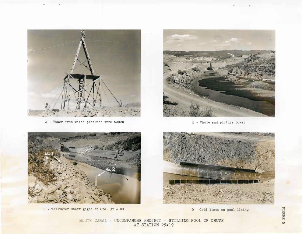
Installations. Tailwater gage No. 1 (figures J and 5 ) was set on
April 20, 19.36, and levels were run to it from a bench mark to establish
its rela.tion to sea level datum. The gage was located on the right bank
approximately 310 feet downstream from the end of the new linin g. The
zero of this gage is :=::t elevation 6421 . 24, U . S . G. S . datum. Later a
similar gage (No. 2) was placed farther out in the canal so as to record
the lower flows, (figure 5 ) .
On April 29, 1936, a break occurred in the floor of the canal below
the section generally referred to as the "Seven-drop Section, " ( figure 3) .
It was necessary to shut the water out of the canal to make repairs .
In changing the discharge in this canal the rate of change, whether an
increase or decrease , is never more than 100 second-feet per hour . At
this rate upwards of eight hours are required to empty the canal when
it is flowing full and an equal amount of time is required to raise the
flow from zero to maxirm.un discharge. As soon as the water started to
recede at the chute two men were stationed at the gages and instructed
to record the gage reading every 15 minutes. This was done and the data
were plotted on the tailwa.ter curve sheet (figure 6) .
After all of the flow was turned out of the canal several photographs
were taken (figure 7) to show the condition of the channel immediately
below the pool. To have a comparison by pictures of the flow conditions in the model and in the prototype , a grid such as was used on the model
pool wall was painted on the right wing wall of the prototype pool with
red and white kalsomine (figure 5 ) .
The location of the grid system on the model was furnished by the
Denver office . The grid consisted of four-foot squares on the center line
projected upon the right wing wall . The vertical line J was at the
intersection of the chute floor and the pool floor, and the upper
horizontal line 12 feet abc,ve the same point.
The line J was locs.te.d (figure 7D) a.nd the grid system la.id out
from it. It was found from a comparison of the model and prototype
4
Page 10
7
A - Tower from wh ich pictur es were t aken
C - Tailwater staff gages at Sta . 37 + 00
.. � �� .. - .. .. .
B - Chute and picture tower
,,��,�t�Jll1 . D - Grid lines on pool lining
SvUTH CANAL - UNCOMPAHGRE PROJECT - STILLING POOL OF CHUTE AT STATION 25*19
� H
CJ1
Page 11
-6• 24
- 2) � ::::> f-<l: Cl
(f)
0 -20(/)
::5 1--
z
- f-<l: - > w _j
-1 8 w ,_
V / ._1 6
/v
/ ,, I
V /
/441 4 0 1 0 0
I
. .
® ®
/
®
/
200
�
/
'X'. X
®
129
./ V
/ /'}
--
I
I 3 00
" X
X
(� ®
l---<-,,,-
--
F i e l d O b s e rva t i on s - _ .
X
® � ---�
'
- -
· - • � . -�·- �
X X
X
I ei
®
� ---
X
'; ---� ) '
u X
li1 ®
® "'
v ---
-
- - M o d e l Stu d i e s
-
---1--·- ---
400 5 0 0 6 0 0 DI SCHARGE C . F . S .
X x �
0 � 19 =
4- 2 1 - 3 6, , I I
' 4 - 2 2 - 36- - - ',
.. X 'X
" �®
129
--..--i.-----
I I � - 4- 2 8 - 3 6
, tt I
,:, �4 - 2 9 - 3 6
" ®Y)._ @ X@ 13,
� ®
--l----0-
---
l---
·-
® R i s i n g S t a ge I I I I I I
� F a i l i n g St age
. . -
U N C O M PA H GRE P R O J E C T C O L O.
SOUTH CANAL TAi l WATE R RATING CUR V E
CH U TE A T S TA . 2 5 + 19
700 800 900
0
L.-G --�
C
�--r--
1 0 0 0
� G') C :::0 IT1
G'l
Page 12
. "
A - Restriction below sti lling pool looking upstream
C - Painting grid lines on wall of stilling pool
B - Restrict ion below stilling pool Looking downstream
D - Pa inting grid lines on wall of st i l l ing pool
SOU'I'H CANAL - UNCOMPAHGRE PROJECT - STILLING POOL OF CHUTE AT STATION 25 i 19
's:I H
--.J
Page 13
pictures that the grid systems did not agree . A check of dimensions
of the prototype grid system disclosed that due to an error in meaS'.lre
men ts the horizontal lines had been placed six-tenths of [, foot lower
than the same lines on the model. This error resulted because the pool v;a.s filled with water to depth of approximately 6½ feet and the top of
the training wall was necessarily used as a control point.
It was necessary to construct e. tower to obtain photogr�phs of the
flow conditions similar to those from the model. The point on this tower from which the photographs were taken was 122 feet from the center
line of the stilling pool and on a line perpendicular to the centerline
at J . The base of the tower was at elevation 6454. 52 while the top was
at 6483.12 or 28½ feet above ground level (figure 5 ) . The ground level
was 27 .87 feet above the top of + he sirle vralls of the pool.
Procedure. At 5 : 00 a .m . May 2, 19;6 , the headgRte of the cansl
was opened allowing some water to pass into the tunnel . At 6 : 00 a .m.
the gate immediately above the chute and slightly below the recording
gage was opened and data were then recorded at both gages simultaneously.
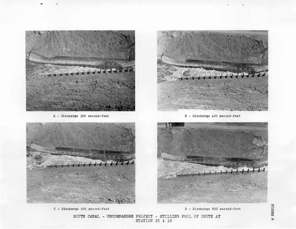
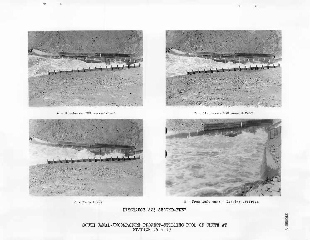
Beginning at the discharge of 300 second-feet, two still pictures and
several fe,··t of movie film were taken from the tower and several feet
of movie film were taken from two positions ne&r the pool. This procedure
was followed &t every 100 second-foot increase in discharge ( figures 6,
7 , 8, 9 and 10) . This work of picture taking and gage reading continued
until 2 :00 p.m. at which time the dischc.rge became const1: nt at 825 second
feet.
All data obtained were computed and plotted on the model tailwater
curve sheet (figure 2 ) . In studying this sheet it will be observed that
the points obt1:dned durine; the fall show a higher tailwater elevation
for 1., given discharge than the points obtainPd during the rise. This
lag was expected beca.use the grade in the earth section downstream is
very flet . A mean curve through all the points obtained is consistently higher than the curve used for the oper8tion of the model .
Page 14
•
A - Discharge JOO second-reet B - Discharge 400 second-reet
C - Discharge 500 second -re et D - Discharge 600 second-reet
SOUTH CANAL - UNCOMPAHGRE PROJECT - STILLING POOL OF CHUTE AT
STATION 25 t 19 (J)
Page 15
...
. •
,��;:H/:;;;;:;}:}::} :�J;�f-:L --� -f.� -::-�'<-.1
--- --t�-::�� ;:�. � ��-.. �
A - Di scharge 700 second-feet
:tlif jifd�tJt�:Jf:;t.� ·, .. , .••.•• <> · )
. · · -� � L ,
J -.� � "#;
, . �·- .,
,.,..,. . .
�'
B - Dis char�e 800 second-fee t
C - From tov1er D - From left bank - Looking upstream
DISCHARGE 825 SECOND-FEE!'
SOUTH CANAL-UNCOMPAHGRE PROJECT-STILLING POOL OF CHUTE AT STATION 2 5 + 19 <O
Page 16
• "' -'-' "
• ,:. - .:.· ;--- l
..__ .. . ,, :• - �I;� ..... · :
A - Discharge 865 second-feet B - Chut e & pool at Station 25 L 19
Discharge approximately 650 second-feet
Spray from pool with di scharge of 800 second-feet D - Upstream end of hydraulic jump .
SOUTH CANAL
SOUTH CANAL-UNCOMPAHGRE PROJECT-STILLING POOL OF CHUTE AT STATION 2 5 + 19
"'.I H
I-'
0