U.P.B. Sci. Bull., Series D, Vol. 81, Iss. 4, 2019 ISSN 1454-2358 STUDY OF THE PARTICLE MOTION ON A MANURE FERTILIZER SPREADER Vasilica ŞTEFAN 1 , Ladislau DAVID 2 , Lucreţia POPA 3 , Radu CIUPERCĂ 4 , Ana ZAICA 5 , Ancuţa NEDELCU 6 , Alexandra ANGHELET 7 The purpose of this study is to contribute to the development of manure fertilizer spreader for improving the distribution uniformity path. The relations between design parameters of the distribution machine and the material used are taken into consideration, relations that have logical-mathematical and theoretical foundations in classical mechanics. Also, an equation that is used to calculate the necessary time for the manure to reach the soil is given together with different working hypotheses. Based on the made hypothesis, a mathematical model was proposed, and some movement situations were simulated. The presented paper is one of a series analysing the manure spreader. Keywords: manure spreader, influence factor, spreading, simulate. 1. Introduction It is well known that any livestock production system has an unavoidable by-product such as manure. These organic fertilizers used in agriculture provide a part of the total of nutritional elements for plant feeding, and contribute to improving the physical, chemical and biological characteristics of the soil and raise the humus content [1;2]. The different and often highly variable biological, chemical, and physical properties of livestock manure can result in both positive and negative impacts on air, soil, water, fauna, and flora [1;2]. A highly valuable fertilizer and amendment for soil-crop agricultural systems when properly 1 Phd. Stud. Eng., National Institute of Research - Development for Machines and Installations Designed to Agriculture and Food Industry – INMA Bucharest, e-mail: [email protected]; 2 Prof. Phd., Biotechnical Systems Engineering, POLITEHNICA University of Bucharest, e- mail:[email protected]3 Phd. Eng., National Institute of Research - Development for Machines and Installations Designed to Agriculture and Food Industry – INMA Bucharest, e-mail: [email protected]; 4 Phd. Eng., National Institute of Research - Development for Machines and Installations Designed to Agriculture and Food Industry – INMA Bucharest, e-mail: [email protected]; 5 Phd. Stud. Eng., National Institute of Research - Development for Machines and Installations Designed to Agriculture and Food Industry – INMA Bucharest, e-mail: [email protected]6 Phd. Eng., National Institute of Research - Development for Machines and Installations Designed to Agriculture and Food Industry – INMA Bucharest, e-mail:; [email protected]; 7 Phd. Stud. Eng., Development for Machines and Installations Designed to Agriculture and Food Industry – INMA Bucharest, [email protected]
STUDY OF THE PARTICLE MOTION ON A MANURE FERTILIZER SPREADER
Vasilica ŞTEFAN1, Ladislau DAVID2, Lucreţia POPA3, Radu CIUPERCĂ4,
Ana ZAICA5, Ancuţa NEDELCU6, Alexandra ANGHELET7
The purpose of this study is to contribute to the development of manure
fertilizer spreader for improving the distribution uniformity path. The relations between design parameters of the distribution machine and the material used are taken into consideration, relations that have logical-mathematical and theoretical foundations in classical mechanics. Also, an equation that is used to calculate the necessary time for the manure to reach the soil is given together with different working hypotheses. Based on the made hypothesis, a mathematical model was proposed, and some movement situations were simulated. The presented paper is one of a series analysing the manure spreader.
It is well known that any livestock production system has an unavoidable by-product such as manure. These organic fertilizers used in agriculture provide a part of the total of nutritional elements for plant feeding, and contribute to improving the physical, chemical and biological characteristics of the soil and raise the humus content [1;2]. The different and often highly variable biological, chemical, and physical properties of livestock manure can result in both positive and negative impacts on air, soil, water, fauna, and flora [1;2]. A highly valuable fertilizer and amendment for soil-crop agricultural systems when properly
1 Phd. Stud. Eng., National Institute of Research - Development for Machines and Installations Designed to Agriculture and Food Industry – INMA Bucharest, e-mail: [email protected]; 2 Prof. Phd., Biotechnical Systems Engineering, POLITEHNICA University of Bucharest, e-mail:[email protected] 3 Phd. Eng., National Institute of Research - Development for Machines and Installations Designed to Agriculture and Food Industry – INMA Bucharest, e-mail: [email protected]; 4 Phd. Eng., National Institute of Research - Development for Machines and Installations Designed to Agriculture and Food Industry – INMA Bucharest, e-mail: [email protected]; 5 Phd. Stud. Eng., National Institute of Research - Development for Machines and Installations Designed to Agriculture and Food Industry – INMA Bucharest, e-mail: [email protected] 6 Phd. Eng., National Institute of Research - Development for Machines and Installations Designed to Agriculture and Food Industry – INMA Bucharest, e-mail:; [email protected]; 7 Phd. Stud. Eng., Development for Machines and Installations Designed to Agriculture and Food Industry – INMA Bucharest, [email protected]
368 Vasilica Ştefan , L. David, Lucreţia Popa, R. Ciupercă, Ana Zaica, Ancuţa Nedelcu, Alexandra Anghelet
managed, manure can also become an important source of pollution when the management systems are deficient.
As it was shown in [1] the main objective of any land application operation for livestock manure is to supply the receiving soil-crop system with a controlled application rate of manure that matches the local requirements of soils and crops and to distribute this manure as uniformly as possible on or under the soil surface. Application rate and uniformity control on land application equipment for livestock manure are governed by [1]:
QNL V
=⋅
(1)
where: N = desired application rate of manure (kg/m2), Q = manure flow rate coming out of the land application equipment (kg/s), L = effective application width of the equipment (m), V = travel speed of the land application equipment (m/s). Since the operators have a degree of control over all three factors (flow
rate, travel speed, application rate) the longitudinal uniformity can be seriously affected. Manure flow rate can be adjusted for all spreaders but the procedure is specific depending on design. As it is shown in [2,3] the flow rate is adjusted by changing the power take-off (PTO) speed, apron speed or ram speed. Higher speed increases flow rate and slower speed decreases flow rate. Unloading rate may also be changed by increasing or decreasing the discharge opening (hydraulic end gate on a box-type or slinger spreader or the discharge valve on a tank spreader). Changing the pressure inside a tank spreader also affects the rate of unloading. Adjusting ground speed of the application equipment, while leaving unloading rate constant, is an easy method to adjust application rate. This is also an important reason for the application operator to be diligent about maintaining a constant ground speed for uniform application [2].
An acceptable single-pass spread pattern can be described as one which is symmetrical on either side of the centreline allowing for uniform overlapping between swaths. Fig.1 presents ideal or acceptable single-pass patterns. A flat top pattern (Fig. 1 a) has a trapezoidal shape with uniform slopes on either side. An oval or Gaussian distribution pattern (Fig. 1 b) provides 60% effective coverage [2,4,5]. In other words, 20% of the swath width should be overlapped in the adjacent passes to generate a uniform distribution. The pyramid pattern (Fig. 1 c) indicates that the effective swath width should be only 50% of the theoretical spread width [6,7].
Study of the particle motion on a manure fertilizer spreader 369
(a) (b) (c)
Fig.1. Desirable single-pass distribution patterns for manure spreaders; flat top (a), oval or Gaussian (b) and pyramid-shaped (c) [4,5]
Some examples of undesirable spread patterns are presented in Fig. 2.
These spread patterns can occur due to a malfunctioning spreader, physical variability of a fertilizer, worn spreader hardware and driving pattern not adapted to the field shape [6,7]. If one of these unsatisfactory spread patterns are found during testing, then adjustment of spreader settings is required.
(a) (b) (c)
Fig.2. Skewed single-pass distribution pattern [4,5].(a) “M” shaped single-pass distribution pattern; (b) W” shaped single-pass distribution pattern, (c) Skewed single-pass
distribution pattern
Single-pass patterns help establish the pattern shape from a spreader but do not represent the resulting pattern across a field since overlap is required on adjacent spreader passes. Simulated overlap patterns are generated using a single-pass pattern, a given spread width and the direction of adjacent passes.
Fig.3. Graphical representation of using a single-pass pattern to generate the simulated
overlap spread pattern indicated by the orange dots and line.[4]
3. Material and method
As it was shown in the previous work [8] the simplest mathematical model for spreading the fertilizer particles is that of material point. It first moves on a fixed surface having the guiding role (rotors helical surface) and after it leaves this
370 Vasilica Ştefan , L. David, Lucreţia Popa, R. Ciupercă, Ana Zaica, Ancuţa Nedelcu, Alexandra Anghelet
surface it moves freely in gravity field, in the air. Obviously, the approximation of a fertilizer particle as a material point is accompanied by an abstract presentation/error that automatically leads to other errors in comparison with reality. Manure particles spread don’t have regular shape; they have an irregular surface (between 1 mm and 60 mm), different mass and can adhere between them as large groups (by cohesion). Though, at different optimum humidity and certain atmospheric conditions it can be admitted that material particles spread behave as material points [8]. Another aspect is that the air resistance was not taken into consideration because of the difficulty of choosing the shape and size of it.
As a result of arguments above, the equations of material point dynamics are used for mathematical modelling. For simplicity, we divided the trajectory of material point (fertilizer point) in two parts: the first part is the curve described on rotor helical surface, the second one being the curve described by the particle in the air [8].
Movement of one manure particle in the absolute space, where the manure is spread, is a complex movement consisting of the following movements:
- particle movement on disk, after being dislodged from the matter to be spread;
- particle movement in the air after being dislodged from the disk
Fig. 4. Rear delivery vertical-axis beaters MG5 Fig. 5. 3D model of the spreading device [8] Solutions of particle’s motion on the disk will be given for each detaching
area from the helical surface. Initial solutions, namely the manure particle’s ones on helical surface will be given in polar coordinates and then passed to Cartesian coordinate systems. By solving the equation systems on helical surface, are obtained coordinates in r and θ, till the particle detachment, that pass afterwards to Cartesian coordinates oijxijyijzij, i=1,..,4 ,j=1,2,3. Then, particle movement in gravitational field is solved, aiming to eventually determine the coordinates of trajectories crossing point with plan OXYZ (soil).
For exemplification, we shall consider the helical surface with right winding. K(r) function is considered to be equal to zero because the surface radial
Study of the particle motion on a manure fertilizer spreader 371
deformation is zero for classic plane helical surface. Helical surface equations become:
cossin( ) , 0,
x ry rz K r p p p R
θθ
θ
= = = + > ∈
(2)
According to the fundamental law of dynamics (Newton’s 2nd law), the motion equation of the material point M on surface S against a fixed reference inertial system (XOYZ) (Fig. 3), is in accordance with [9,10,11,12].
c fma F G N F= + + +
(3)
where: cF
is the centrifugal force; G
particle gravity force; N
surface reaction force; fF
the friction force between particle and surface; Coriolis acceleration and transport acceleration are negligible in
comparison with gravitational acceleration, as they have very small values according to [13].
Movement equations on radial and angular directions are: 2 2
2 2 2 2 2 2 2 2
2 22 2
2 2 2 2 2 2 2 2 2 2 2 2
2m( ) ( )( )
2 2( )( )
mgr prr rr r m r mr p r p r r p
r pmrr mgp mgr prrm r p mr p r p r p r p r r p
θθ θ µθ
θθ θθ µθ
− = − − ⋅
+ + + +
+ + + = − − − + + + + + +
(4) With initial conditions that take into account the speed of material transport
to the rotors (vt), the initial position of material particle (initial radius and angle) r0,θ0 (relations (4)), the relations for speed can be written as follows:
0 0 0
0 0 0
0 0
00
0
cos( )cos( )
r cos( )cos( )
x ry r
vtvt
r
θθθ
θθ ω
= ⋅= ⋅= ⋅
⋅= +
(5)
The solution of equation (4) is given in equation (5), which defines the radius of motion as a function of time, r(t). The movement of a manure piece along the rotor surface is also a function of time and is influenced by the coefficient of friction (μ) of the manure piece on the surface on which it moves,
372 Vasilica Ştefan , L. David, Lucreţia Popa, R. Ciupercă, Ana Zaica, Ancuţa Nedelcu, Alexandra Anghelet
the initial distance of the manure piece from the centre of rotation (r0) and the rotor angular velocity (ω).
In Cartesian coordinates, the speed is given by the following relations:
0 0 0 0 0 0
0 0 0 0 0 0
x r cos( ) r sin( )
r sin( ) r cos( )y
θ θ θ
θ θ θ
= − ⋅
= + ⋅
(6)
where vt is speed with which each particle reaches the helical surface (conveyor speed).
Eq. system (4) cannot be analytically solved, but only numerically on computer, because it contains the second derivatives of r and θ depending on first derivatives and other parameters of the system.
Motion equations in the air are determined by the theory of slanting movement [9,10] applied on manure spreader apparatus (Eqs. 7):
0 0 0
0 0 0
2 20 0 0 0 0 0
( ) ( )( ) ( )
( ) ( )2 2
x t x t t xy t y t t y
g gz t t z g t t z z t t
= − +
= − + = − + + ⋅ + − −
(7)
where t is the time passed by a flying particle up to its landing on the soil (z=0); t0 - time after which the particle leaves the rotor from its helical surface described above;
0x - initial speed of particle on axis ox; 0y - initial speed of particle on axis oy;
0z - initial speed of particle on axis oz; z0 - height from which the particle leaves the rotor; g - gravitational acceleration.
Solving the third equation from the system (7), gives the time after which the particle lands on the soil (z=0).
We shall write down the coefficients of t as follows:
2gA −
= , 0 0B z gt= + and 20 0 0 02
gC z z t t= − −
The resulting solutions are: 2
1
2
2
42
42
B B A CtA
B B A CtA
− + + ⋅ ⋅=
⋅
− − + ⋅ ⋅ = ⋅
(8)
where tlanding is maximum of t1 and t2
Study of the particle motion on a manure fertilizer spreader 373
In order to solve the differential equations (4) on the computer using the Fourth Order Runge Kutta method, a MathCad program was used. The system of differential equations (4) was introduced in explicit form, i.e. by explaining the second derivatives of r and θ depending on the first derivatives and the other parameters of the system. Equations (4) and (5) describe the movement of manure particles from the first contact with the rotor until they reach the soil surface.
4. Results and discussion
Components of the movement on helical surface in the local reference system The simulation was made on a three-spiral rotor with a total height of h=0.9 m (Fig.6). The spiral started at 1.2 m above the soil, so the first spiral of the rotor started at H=1.2 m from θ =0 to 360° and a pitch p=0.3 m, and continues the same way until the third spiral ends. The maxim height for a particle to leave the spiral is 2.1 m. The angular coordinate is given by the radius of the particle position which can be from r0=057 to r=0.172 m. Numerical simulations were made on rotor no. 4 in Fig. 5 (the left one). We consider X axis as the longitudinal axis of the machine and the Y axis in the transversal direction. The graphic representation of the rotor (upper view) in Fig. 7 is offset by 900 in the left direction, fact generated by axis representation.
Calculating their trajectories, we shall be able to estimate time, coordinates and speed of particle that leaves the surface. As criteria of leaving the helical surface by manure particles, at least two may be taken into consideration (but not at the same time):
- particle detachment from the rotor surface is given by condition 1 / 2r φ> ; 1φ being the rotor diameter, - particle detachment from the rotor surface even for / 2r φ< because of
aerodynamic force growth over the friction force with the surface and gravitational force generated by mass shape and distribution in manure particle. For exemplification a series of initial conditions were considered and the results were explained; the rotor radius (r), the rotor rotational frequency (n), the rotor vertical distance from the ground (H) and the coefficient of friction between the manure and the surface on which it slides are entered in the program. The result is a distribution pattern for a wide−angle manure spreader. Based on this distribution pattern, results can be evaluated and the boundary conditions changed.
For the boundary conditions, rotor rotational frequency n = 530 rot/min; rotor radius (r), radius of particle starting point r0 = 0.115 m; height above the soil H = 1.2 (for θ=0°); the inclination of the rotor relative to the vertical axis - 10° (Fig.7) and the coefficient of friction between the manure and the surface on
374 Vasilica Ştefan , L. David, Lucreţia Popa, R. Ciupercă, Ana Zaica, Ancuţa Nedelcu, Alexandra Anghelet
which it slides μ=0.8 are entered into the program. We consider that the machine is supplied in the 0-90° and 0-270° quadrant. That is why all the simulated points will start from here. It is expected that the particle starting point from the rotor helical surface is in the 180-270° quadrant. If any of these points gets in 90-0°, their trajectory shows that the point is sent back into the machine, in the supply zone. There may be a discussion about the point that arrives on the side rotor, but we don’t try to solve this situation at this stage of research.
Radial coordinate Fig. 8 shows the variation in time of the radial coordinate on the disk in
the time interval between the initial moment r0 = 0.015m and the moment of detachment from the disk, meaning r= 0.175 m (the dimensions of the machine). This movement happens in time t = 0.013 s.
Angular coordinate Angular coordinate θ, in the sense of the rotational speed starts at 270° and
arrives to 229° (41°) from time t0 = 0 to te = 0.013s.
Fig 6. Rotor spreader Fig. 7. Particle movement on helical surface
Study of the particle motion on a manure fertilizer spreader 375
0 5 10 3−× 0.01 0.0150.05
0.1
0.15
0.2
rad
ial
co
ord
inate
, m
time, s time, s
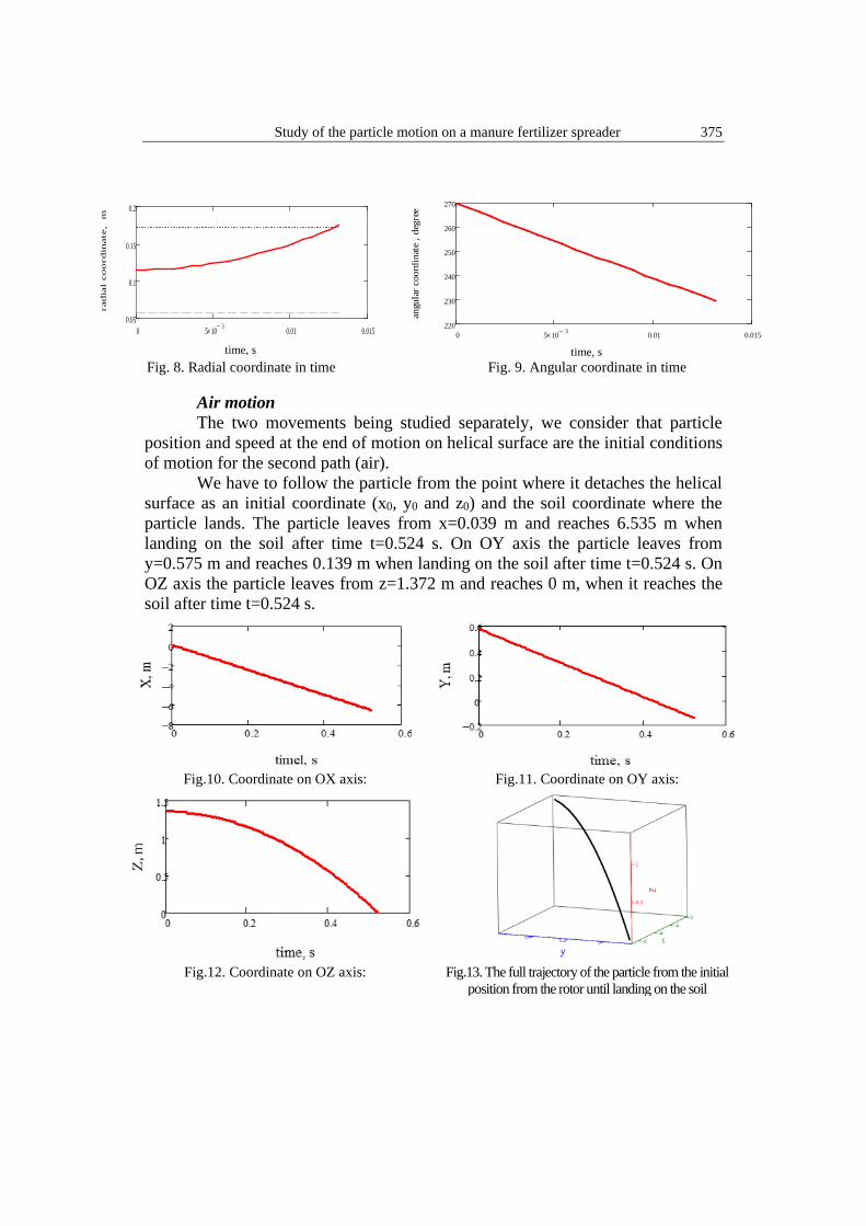
Fig. 8. Radial coordinate in time
Fig. 9. Angular coordinate in time
Air motion The two movements being studied separately, we consider that particle
position and speed at the end of motion on helical surface are the initial conditions of motion for the second path (air).
We have to follow the particle from the point where it detaches the helical surface as an initial coordinate (x0, y0 and z0) and the soil coordinate where the particle lands. The particle leaves from x=0.039 m and reaches 6.535 m when landing on the soil after time t=0.524 s. On OY axis the particle leaves from y=0.575 m and reaches 0.139 m when landing on the soil after time t=0.524 s. On OZ axis the particle leaves from z=1.372 m and reaches 0 m, when it reaches the soil after time t=0.524 s.
Fig.10. Coordinate on OX axis: Fig.11. Coordinate on OY axis:
Fig.12. Coordinate on OZ axis: Fig.13. The full trajectory of the particle from the initial
position from the rotor until landing on the soil
0 5 10 3−× 0.01 0.015220
230
240
250
260
270
angu
lar c
oord
inat
e , d
egre
e
376 Vasilica Ştefan , L. David, Lucreţia Popa, R. Ciupercă, Ana Zaica, Ancuţa Nedelcu, Alexandra Anghelet
After describing the motion of the particle, we can make some appreciations about the influence of any of the machine design parameters and material.
Movement of a manure piece on the rotor helical surface based on the rotor rotational frequency and initial position of manure piece
The curve described by a manure piece along the helical surface varies with the variation of the rotor rotational frequency, from 100 to 700 min−1 for three radii of initial piece position. Variations of the rotor rotational frequency also affect the rotor peripheral speed; thus, the speed of a piece detaching the rotor increases as the rotor rotational frequency increases. To observe changes in the path of a manure piece on the rotor, 9 simulations were made and they are shown in Fig. 14. The intersection point with the soil was found and shown in Fig 15. Xsoil coordinate is negative because we consider the positive X axis from the rotors to the tractor and minus sign from the rotors towards the area behind the machine, where the manure spreading takes place.
Table 1 Particles soil coordinate depending on rotational frequency and initial piece position
n=100 rot/min r=0.075
m
n=300 rot/min r=0.075
m
n=700 rot/min r=0.075
m
n=100 rot/min r=0.114
m
n=300 rot/min r=0.114
m
n=700 rot/min r=0.114
m
n=100 rot/min r=0.162
m
n=300 rot/min r=0.162
m
n=700 rot/min r=0.162
m x soil [m] -1.145 -3.358 -7.34 -1.193 -3.291 -7,586 -0.95 -2.588 -5.294 y soil [m] -1.052 -1.346 -2.02 -0.564 -0.265 -0.013 -0.372 -0.033 -0.506 r [rad/s] 1.632 5.379 12.442 1.534 4.927 11.95 0.813 2.612 6.144
ts [s] 0.579 0.479 0,467 0,533 0.476 0.456 0.478 0.434 0.379 The length of the manure piece path decreases with an increase in the
distance between the initial position of the piece and the rotor centre (fig. 14).
Fig.14. Movement of a manure particle for various
rotational frequencies on the helical surface Fig.15. Increasing the longitudinal distance with increasing the rotor
frequency
Study of the particle motion on a manure fertilizer spreader 377
Movement of a manure piece on the rotor based on the coefficient of friction Since in practice different fertilizer types are used for fertilization having different physical properties [14,15], the influence of friction with the metallic helical surface for different coefficients of friction (taken from the literature) is analyzed [3,7]. Four values of the coefficient of friction were used, µ = 0.3; 0.5; 0.7, 0.9 [13,16,17] for radius r = 0.115m at a speed n = 300 min-1.
Fig.16 (a). Movement of a manure piece for various coefficients of friction
Fig.16 (b). Movement of a manure piece for various coefficients of friction - detailed view
Simulation showed that the travel path length increases with an increase in
the coefficient of friction. At µ = 0.3, the manure piece rotates around the axis of rotor for about 39°, and at µ = 0.95 it is 42° (In Fig 7 are shown the senses and notations). The coefficient of friction has a smaller influence on spreading than anticipated. A change of the coefficient of friction has no significant influence on a piece’s travel on the rotor or on its speed on detaching the rotor, fact also shown in paper [13].
Movement of a manure piece on the rotor based on the rotor height For exemplification we took 3 points that leave the rotor on spiral 1, 2 and
3 at the same initial radius of the piece (r=0,115) and the same θ corresponding to each spiral at 530 min-1.
Table 2
Particles soil coordinate depending on rotor height θ xsoil [m] ysoil [m] H starting point [m]
270 – first spiral -6.535 -0.139 1.372 270+360-second spiral -7.171 -0.213 1.667 270+360x2 third spiral -7.748 -0.281 1.962
378 Vasilica Ştefan , L. David, Lucreţia Popa, R. Ciupercă, Ana Zaica, Ancuţa Nedelcu, Alexandra Anghelet
Fig.17. Particle trajectory depending on rotor height
Simulation showed that as the manure piece’s initial position is higher, the
range of the manure increases.
6. Conclusions
A theoretical model of a manure piece’s trajectory from the machine to the soil surface has been carried out in Mathcad and some possible situations have been simulated.
The simulations results indicated that design parameters can be adapted for good results. The manure piece trajectory from the rotor surface to the soil depends more on rotational frequencies, initial radius position, rotor height, rotor size and is less influenced by friction coefficient between manure and rotor surface.
The predictions of the numerical models should be in agreement with the experimental results obtained with the simulated machine. Since air resistance wasn’t taken into consideration, because of the irregular shape and size, the real trajectory is expected to be less than the theoretical one.
The results of the study indicate that the model can be used to simulate field spreading performance of the developed manure fertilizer, evaluate the uniformity of fertilizing spreading and improve the conventional empirical variable rate fertilizer application methods. In the future, the authors plan to determinate accurate fertilizer application rate varying the demand for crop using different type of solid organic fertilizers. The accuracy and validity of the simulation models can then be certified.
Study of the particle motion on a manure fertilizer spreader 379
R E F E R E N C E S
[1]. J.J. Lenehan, D. Keppel, J. Perros, I.M. Scotford and T.R. Cumby, “Development of electronic control system for SWAMP prototype slurry tanker”, EurAgEng Paper No. 98-E-011, Silsoe, UK, 1998.
[3]. V. Ştefan (Popa), L. David, A. Petcu, A. Zaica, G. Lazar, L. Popa, R. Ciupercă,A. Nedelcu and D. Veringa (2015), “Considerations on the construction of the distributing equipment of solid organic fertilizers”, International Symposium ISB - INMA TEH, 29 oct. – 31 oct. 2015, Romania, pp.697-704.
[4]. K. T. Ravinder, Effect of vane shape and fertilizer product on spread uniformity using a dual-disc spinner spreader. Master Thesis, Faculty of Auburn University, 2014.
[5]. J. P. Fulton and C. Ogburn, “Calibrating Dry Broadcast Fertilizer Applicators”, Alabama Cooperative Extension System, ANR-0724, 1–4 (ACES, 2010).
[6]. L. Stewart and A. Bandel, “Uniform lime and fertilizer spreading”. Maryland Cooperative Extension. University of Maryland, College Park, MD, EB-254, pp. 1-12, 2002.
[7]. ASABE Standards.S341.4: Procedure for measuring distribution uniformity and calibrating granular broadcast spreaders. St. Joseph, Mich., ASABE 2009.
[8]. V Ștefan, P. Cârdei., N.V. Vlăduţ, L. Popa, R. Ciupercă and N. Ungureanu , “Mathematical model for particle motion applied on a manure spreading apparatus used in environmentally friendly technology”, Environmental Engineering and Management Journal, , Vol.17, “Gheorghe Asachi” Technical University of Iasi, Romania, p 217-227, IF 1.096, January 2018.
[9]. V.Vâlcovici, Ş. Bălan and R.Voinea R. Mecanica teoretica - editia a treia (Theoretical Mechanics-third edition), Editura Tehnică Bucureşti,1968.
[10]. I. Cândea, I. Comănescu, I. Cojocaru and I. Sîrbu, Mecanica. Dinamica. Teorie şi aplicaţii (Mechanics. Dynamics. Theory and Applications), Universitatea Transilvania, Brașov, Romania,2003.
[11]. M. Atanasiu, Mecanică (Mechanics), Editura didactica şi pedagogică,Bucureşti, România, 1973.
[12]. I. Roşca I.and C. Ion, Lectures in Mechanics. Kinematics – Dynamics, Polytechnic Institute of Bucharest, Romania.1981.
[13] J. Duhovnik, J. Benedičič and R. Bernik, “Analysis and Design Parameters for Inclined Rotors Used for Manure Dispersal on Broadcast Spreaders for Solid Manures” Transactions of the ASAE, vol. 47(5), pp 1389-1404, 2004.
[14]. V. Ştefan, R. Ciupercă, L. Popa, A. Nedelcu, G. Lazăr, A.S. Petcu and A. Zaica , ”The influence of physical characteristics of solid organic fertilizers on quality of land spreading / Influenţă caracteristicilor fizice ale îngrăşămintelor organice solide asupra calităţii lucrării de împrăştiere”, INMATEH-Agricultural Engineering, vol.46-2, ISSN print: 2068 – 4215, ISSN electronic: 2068 – 2239,.pg.77-84,2015.
[15]. V. Stefan, L. David, L. Popa and Al. Zaica, “Use of theoretical mathematical relations for calculating the application and mass flow rate of a rear delivery vertical-axis manure spreader”, Engineering for Rural Development, pp.1284-1291 Jelgava, 24-26.05.2017.
[16]. J. L Glancey and S. C. Hoffman,” Physical properties of solid waste materials”, Applied Engineering in Agriculture, vol. 12(4), pp. 441−446, 1996.
[17]. F. Pezzi and V. Rondelli, Evaluation of a prototype spreader in the distribution of poultry manure”, Applied Engineering in Agriculture, vol.18(3), pp. 285−291. 2002.