Research ArticleStudy of the Press Fit Bearing-Shaft Joint DimensionalParameters by Analytical and Numerical Approach
Zuzana Murcinkova Petr Baron and Martin Pollak
Faculty of Manufacturing Technologies with a Seat in Presov Technical University of Kosice Kosice Slovakia
Correspondence should be addressed to Martin Pollak martinpollaktukesk
Received 13 February 2018 Revised 5 April 2018 Accepted 11 April 2018 Published 10 May 2018
Academic Editor Aniello Riccio
Copyright copy 2018 Zuzana Murcinkova et al +is is an open access article distributed under the Creative Commons AttributionLicense which permits unrestricted use distribution and reproduction in any medium provided the original work isproperly cited
+e study of press fit bearing-shaft joint dimensional parameters by means of analytical and numerical calculations in order toidentify those parameters of the press fit joints which significantly influence the life of the bearings fitted by pressing is dealt in thispaper +e mounting and conditions of fit joint are the significant factors affecting the operability and life of the bearings andconsequently that of rotating machines and the whole technical units +e aim of the analysis and study is to determine thetangential and radial stress the radial displacement and the influence of the shape features and the size of the interference on thechange of the radii in the press fit bearing-shaft joint in particular the ball bearings of 6014 2RSR C3 type Moreover on the basisof obtained results the paper discusses the impact of shaft dimensional and geometrical accuracy on the bearing lifetime
1 Introduction
+e rolling bearing itself is the multiparameter system andits lifetime is influenced by many parameters Rollingbearings represent reliable parts of long-life machinesprovided they are properly mounted and maintained Re-liable operation of rolling bearings does not lie exclusively inthe quality of the bearings themselves +e life of a rollingbearing is influenced by other factors too +ese are mainlythe operating environment professional installation andproper maintenance +e real operating conditions ofbearings may strongly change the theoretically estimatedbearing life +e well-known equation of bearing life L
calculation is in the form
L aC
F1113874 1113875
p
(1)
where a is the coefficient in range 01divide10 according toexperiences and measurements depending on specialbearing properties and operating conditions C is the basedynamic load rating (in catalogues) it means the load thatresponds to basic bearing life of million revolutions F is theapplied load (the load F is substituted by Femdashequivalentdynamic load) and p is the exponent that is chosen in
accordance with the outcomes of experiments (p 3 for ballbearings and p 103 for roller bearings)
It should be noticed that the range of coefficient a is verywide+e signs of bearing failure can appear in several yearsmonths also in a few days or even a few hours of operation[1] In order to take advantage of the bearingrsquos life potentialinside the machine it is necessary to observe relatively strictrequirements for mounting lubrication clearance bearingsetting and other such requirements If these requirementsare met the bearing is able to work for a long period of time
+e issues of the bearing housing and joint are among themost important factors that may cause subsequent bearingfailures +e bearing properties are fully utilized only whenthe bearing rings are supported throughout the circumferenceand over the entire bearing race width +e fixed contactsurface may be cylindrical or conical in shape alternately itmay be planar in case of the axial bearings +e contactsurfaces must be manufactured with adequate accuracyAppropriate radial locking and adequate fit will only beachieved if the bearing-shaft joint involves interference [2]However there can be a requirement of simple assemblingand dismantling or of enabling the axial displacement of theaxial bearing In these cases it is not possible to choose pressfit joint for the bearing rings In cases where the transition fit
HindawiAdvances in Materials Science and EngineeringVolume 2018 Article ID 2916068 10 pageshttpsdoiorg10115520182916068
is proposed the steps to prevent the possible wear caused byring sliding have to be made [3 4]
2 Literature Review
At present the analytical and numerical methods are availableto design or analyze the t joint In the eld of press t jointsthe analytical solution was used by Lippmann to indicate thatcontact pressure varies with temperature He said that theincrease in temperature leads to a decrease in yield stresscorrecting which causes deformation of the plastic materialthereby reducing the load capacity of the joint [5]
e analytical techniques used to design press t on Lamersquosequations are based on two-dimensional stress analysis in theelastic range Lamersquos solution is limited by its simplistic as-sumptions Zhang et al analyzed a press t joint betweena stepped shaft and ring gear using both analytical and nu-merical methods and concluded that Lamersquos equations un-derestimate the contact pressure by up to 78 [6] eanalytical models have been used to study the contact pressureand stress distribution in press t joints the eect of surfaceroughness and thermal cycles Yang et al highlight the im-portance of surface roughness in the press t joint anddemonstrate experimentally that the extraction load uctuatesup to 300 for Ra values of 024ndash682μm [7] Wang comparedthe performance of lugs under various clearance and in-terference values and he concluded that the use of a carefullyadjusted press t increases the durability of the joint [8]Croccolo et al developed an analytical model to determine thecontact pressure between two dierent materials and said thatif the stiness of both parts is close the actual interference willprobably be less than the estimated interference [9] Mori et algive a broad overview concerning the connection processincluding the connection to ensure the overlap of the pressconnection For ring-tube joining by expansion the authorspoint out that the optimal forming pressure is achieved beforedeformation of the ring that begins to deform plastically At thesame time they suggest that any further increase in the formingpressure results in a negligible increase in the interferencepressure and joint strength e strength of the joint can beincreased by increasing the surface roughness or by cleaningthe contact surfaces [10] Zhang et al have studied the stressdistribution at the interface of a ball bearing in particular onthe edges with the nite element method ey establisheda strength criterion based on two safety factors λs (factor ofsafety to ensure component strength) and λp (factor of safety toensure no slippage on mating surfaces) Boutoutaou et al usednite elements modeling to design a tool for forging shrunkparts to ensure the nal dimensions of the nished product[11] Some recent studies show the advantage of higher res-olution models to understand interference-t joints better
In this paper we analyze and demonstrate the impor-tance of press t joint dimensional parameters and thus wequantify the importance of individual parameters based onboth the analytical and numerical approach e study ofpress t joint is applied on the joint of the ball rolling bearingand the shaft because the accuracy of bearing production isin the micrometer order but in most cases the mounting ofbearing is done by users of shafts that can be manufactured
in dierent accuracies both dimensional and geometricalBoth our analytical and numerical models analyze the di-mensional parameters in the elastic range without takinginto account the roughness of contact surfaces and tem-perature changes caused by the operating state
3 Press Fit Joint and Its Parameters
e press t (also called interference or force t) joint isdened as a xed nondismountable joint ere are someauthors who dened the press t joint as very dicult todismount e mounting of this joint is based on the elasticdeformations in the contact surfaces that are pressed to-gether [12] e contact surfaces are mostly cylindrical inshape but they can also be slightly conical e press tjoints do not require the use of shaft keys as feathers ortappers and slots which would otherwise reduce the strengthof the joint rough this the press t joints can be smaller
In order to obtain a press t joint the following conditionmust be met the mounting diameter of the inner componentmust be larger than the mounting diameter of the outer com-ponent Such a dierence is called interferenceis results in thealreadymentioned elastic deformation which causes stress in thecomponents e stress state can be considered as plane stress(stress generated in the axial direction may be neglected) A tan-gential stress is generated in the tangent direction σt and a radialstress σr is generated in the radial direction (Figure 1) [13 14]
e radial and tangential stress as well as the contactpressure can be calculated analytically according to thethick-walled pressure cylinders theory e tangential stressσt and the radial stress σr are given by
σtr(r) A plusmnB
r2 (2)
where A and B are the integration constants determined byboundary conditions and r is the radius Contact pressurep2 which occurs after the shaft I and the hub II is pressed
d3
d2
σr
σt
σt
σr
Figure 1 Radial and tangential stress occurring in the press tbearing-shaft joint
2 Advances in Materials Science and Engineering
p2 δE
2r2
r23 minus r22( 1113857
2r23 (3)
where δ is the interference E is Youngrsquos modulus of elas-ticity r2 middot (d22) is the radius of shaft I and r3 middot (d32) is theouter radius of hub II (Figures 1 and 2)
+e interference δ is equal to the difference in the outerdiameter of the inner ringmdashhollow shaft and the innerdiameter of the outer ringmdashhub (Figure 2) After pressingthe rI2 radius reduction occurs by ΔrI2 value of the inner ring(hollow shaft) and the outer ring II (hub) on rII2 the radiusincreases by the ΔrII2 value
Radial shaft displacement ΔrI2 (decrease of the originalshaft radiusmdashcompression)
ΔrI2 p2r2
E(1minus μ) (5)
where μ is Poissonrsquos ratioRadial hub displacement ΔrII2 (increase of the original
shaft radiusmdashexpansion)
ΔrII2 p2r2
E
r22 + r23r23 minus r22
+ μ1113888 1113889 (6)
+e load bearing capacity between the pressed hub andthe shaft is mainly due to the size of the interference and it isdetermined by
(i) the wall thickness of the outer component(ii) the type of material used for both connected
components(iii) temperature of the components during mounting
and also their operating temperature(iv) elastic deformation induced by pressing(v) joint length(vi) surface quality of contact surfaces and so on
4 Analytical Solution andNumerical Experiment
Based on our partnerrsquos request we have calculated a pressfit joint of shaft (solid and hollow) with 6014 2RSR C3ball bearing +e results of the analytical calculation wereverified by computer simulation in the environment of thePTC Creo system using the FEM methodmdashfinite element
method (p-version) +e main aim of the calculations andanalyses applied was to study the correlation of the analyticalcalculation of the stress of the press fit joint of the bearingwith the shaft with the results of its numerical simulationand to analyze the changes of the shaft radii and of the innerring of the bearing under the influence of the interference
+e calculation was made for
(i) radial stress(ii) tangential stress(iii) reduction of the radial shaft displacement(iv) increase of the radial hub displacement
41eAnalyticalCalculation of the Press Fit Joint of the Shaftand the Bearing Analysis input values (see Figure 2)
(i) Interference fit in a single-hole system φ70H7p6
(ii) Limit deviations φ70H71113874+0030
0 1113875 φ70p61113874+0051+0032 1113875
(iii) Material steel μ 03 E 2105 MPa(iv) Solid shaft rI1 0 mm rI2 35 mm(v) Hollow shaft rΙ1 20 mm rΙ2 35 mm(vi) Hub rII2 35 mm rII2 414 mm
(radius determined according to dimensions of theinner bearing ring here without groovemdashshapefeature)
411 Interference Calculation Maximum interference δmax
dmax minusDmin 0051 mmminus 0 0051 mm
Minimum interference δmin dmin minusDmax 0032 mmminus0030 mm 0002 mm
Maximum contact pressure according to (3) for δmax
p2 20 785 MPa (7)
Maximum reduction of ΔrI2 shaft radius according to (5)
ΔrI2 000255 mm (8)
Maximum increase of ΔrII2 hub radius according to (6)
ΔrΙΙ2 002295 mm (9)
+en interference δ isδ2
ΔrI211138681113868111386811138681113868
11138681113868111386811138681113868 + ΔrII2 000255 mm + 002295 mm
00255 mm rArr δ 0051 mm
(10)
II
I
p2r2I r2IIr1I
r3II
2δ
Δr2I
Δr2II
Figure 2 Interference in press fit joint
Advances in Materials Science and Engineering 3
412 Shaft Stress Calculation Boundary conditions of thesolid shaft
σIr r r1 0 mm( 1113857 minusp2
σIr r r2 35 mm( 1113857 minusp2(11)
After substituting (11) according to (2) we get
AI minusBI
r21 minusp2
AΙ minusBI
r22 minusp2
(12)
By solving the system of equations (12) we get in-tegration constants AI minusp2 and BI 0
+en according to (11) the tangential and radial stresson r2 radius in a solid shaft has the same value
σIt r r2( 1113857 σIt r r1( 1113857 σIr r r1( 1113857 σIr r r2( 1113857
minusp2 minus20 785 MPa(13)
Boundary conditions of the hollow shaftσIr r r1 20 mm( 1113857 0
σIr r r2 35 mm( 1113857 minusp2(14)
After substituting (14) in (2) we get
AI minusBI
r21 0
AI minusBI
r22 minusp2
(15)
By solving the system of equations (15) we get the in-tegration constants in the form
AI
minusp2 middot r22r22 minus r21
(16)
BI
minusp2 middot r21 middot r22
r22 minus r21 (17)
+en from (2) (16) and (17) the circumferential(tangential) stress in the hollow shaft σIt is
σIt r r1( 1113857 minus2 middot p2 middot r22
r22 minus r21 minus
2 middot 20 785 MPa middot 352 mm2
352 minus 202( ) mm2
minus61 725 MPa
σIt r r2( 1113857 minusp2 middot r22 + r21( 1113857
r22 minus r21
minus20 785 MPa middot 352 + 202( 1113857 mm2
352 minus 202( ) mm2
minus40 940 MPa
(18)
413 Hub Stress Calculation (Solid and Hollow Shaft)Boundary conditions of the hub
σIIr r r2 35 mm( 1113857 minusp2
σIIr r r3 414 mm( 1113857 0(19)
After completing (19 according to (2) we get
AII minusBII
r22 minusp2
AII minusBII
r23 0
(20)
By solving the system of equations (20) we get the in-tegration constants in the form
AII
p2 middot r22r23 minus r22
(21)
BII
p2 middot r23 middot r22
r23 minus r22 (22)
+en from (2) (21) and (22) the circumferential(tangential) stress in the hub σΙΙt is
σIIt r r2( 1113857 p2 middot r22 + r23( 1113857
r23 minus r22
20 785 MPa middot 352 + 4142( 1113857 mm2
4142 minus 352( ) mm2
124 931 MPa
σIIt r r3( 11138572 middot p2 middot r22
r23 minus r22
2 middot 20 785 MPa middot 352 mm2
4142 minus 352( ) mm2 104 146 MPa
(23)
+e final stress field is shown in Figure 3
42 Numerical Simulation of Press Fit Joint +e analyticallycalculated stress and displacement of the analyzed press fitjoint (φ70H7p6) were verified by the p-version of the finiteelement method (FEM) implemented in the Creo Simulatemodule of the PTC Creo parametric system In this calcu-lation the mesh of finite elements does not change duringthe computing and the required accuracy is achieved byincreasing the polynomial order of the polynomial shapefunctions [15] +e maximum polynomial order obtainablein Creo Simulate is 9 +is is the case of higher order ap-proximation +ese finite elements are designated as p-el-ements +ey are characterized by greater shape diversityand a smaller number compared to h-elements Some au-thors believe that using p-elements even complex structurescan be efficiently discretized with solid elements (three-dimensional elements) even if the aspect ratio of the ele-ments becomes very large Moreover p-version of FEM al-lows predicting the structural behavior of three-dimensional
4 Advances in Materials Science and Engineering
plates and shells with approximately the same amount ofdegrees of freedom as in the two-dimensional case yet sig-nicantly more accurate due to the three-dimensional model[16]
e presented numerical model consists of 3741 p-niteelementsmdashtetrahedrons (Figure 4) Maximum achievedpolynomial order of shape functions is 5 and the number ofequations in last pass is 104459 in this computation edetermined stress error of maximal principal stress is 01
One-eighth of the press t joint is modeled because ofsymmetrical boundary conditions Interference t isa type of model for nonlinear analysis with contact region
in the contact surface e computational method is theNewton-Raphson method Five loading intervals andlocalized mesh renement with convergence on contactforces are used for computation Figure 4 shows magni-tude of displacement elds having their maxima on thecontact surfaces
e following tables (Tables 1ndash3) show the comparisonof the radial tangential stress values and the radial dis-placements in analytical and numerical calculations eanalytical and numerical solutions match very closelyranging from 003 to 475 at the given nite elementparameter setting e model is reliable
XY
Z
XY
Z
Figure 4 Displacement eld (magnitude) of the shaft (left) and the hub with nite p-element mesh
Solid sha with the hub
Hollow sha with the hub
r3
r3
r2
r2
p2
p2
II
II
I
r1
I
IIσr (r3) = 0 IIσt (r3) = 10415
IIσt (r2) = 12493
0
0
ndash
+
+
ndash
IIσr (r2) = 2079
Iσr(r1) = 2079
I(r2) = 2079(r2) = σrIσt
IIσr (r3) = 0 IIσt (r3) = 10415
IIσt (r2) = 12493II(r2) = 2079(r2) = σrIσr
Iσr(r1) = 0Iσt (r1) = 6173
Iσt (r2) = 4094
Figure 3 Stress in the solid and the hollow shaft with the hub (MPa)
Advances in Materials Science and Engineering 5
43 Influence of Shape Features An analytical solutionexists for the shaft of a cylindrical (or tube) shape and thetube-shaped hub (without shape features) In the next stepof the analysis the effect of the geometry of the hub on thestress and displacement fields in the press fit joint wasexamined Any change in the geometry for which theanalytical solution is derived changes the resulting values+en the analytical calculation can be considered asapproximate In case the analysis deals with a bearingmounted by pressing the inner bearing ring includes theinner race that changes the original geometry of thecomputational model
A press fit joint model (Figure 5) was developed in thePTC Creo environment as an assembly of 3D geometricalmodels of the shaft and the inner ring bearing Since theexamined press fit joint is symmetrical in three planes it issufficient to use only the eighth part of the model (Figure 5)and to define symmetry conditions for entities lying in thesymmetry planes
+e 6014 2RSR C3 bearing is made of bearing steel +ismaterial is classified as a type of structural steel although itschemical composition and at the same time their propertiescorrespond more with the tool steel types Steel types forroller bearings are hypereutectoid chromium steel types withthe basic carbon content of about 1 and the chromiumcontent of about 15
Figures 6 and 7 show selected results of static analysis ofradial and tangential stress distribution along the hubthickness that is edge highlighted in Figure 5 of the pressfit joint connecting the shaft and the inner ring of thebearing
+e effect of the changed geometry that is the effect ofthe internal bearing race groove on the resulting stress and
displacement after pressing is shown in Figures 8ndash11respectively
Figure 11 shows the distribution of the displacementfield (magnitude) of the shaft and the inner bearing ring Itcan be compared with the displacement field without theshape features in Figure 4 Naturally the shape features (theinner race groove of the bearing) change the distribution andthe values of the fields In this case the change in fielddistribution is slightly modified especially in the radius ofthe inner bearing rolling race
44 Effect of the Interference Size and Discussion In the nextstep it is necessary to identify the size of the interference ofthe press fit joint and the effect of the change in the diameterdisplacement of the inner bearing rolling race ΔdII
0 whichaffects the important quantity that is size of the bearingrsquosradial clearance Values of the diameter displacement of theinner bearing rolling race ΔdII
0 for individual interferences ofpress fit Oslash70 H7k6 H7p6 H7r6 and H7s6 as a result ofpressing are processed in Figure 12
Figure 12 makes it evident that the size of the in-terference essentially influences the size of the diameterdisplacement of the inner bearing rolling race ΔdII
0 In theanalyzed press fit 88 of the size of the interference δ is thediameter displacement of the inner bearing rolling race ΔdII
0 which is a very significant proportion Moreover we ana-lyzed how the effect of the interference size on the diameterof the bearing race can be reduced +e increased hubthickness reduces the percentage of interference proportionbut not substantially At the same time it significantly in-creases contact pressure which is a disadvantage
Moreover we have to realize that any deviation of theideal shape of pressed contact surfaces considerably in-fluences the shape of the bearing rolling race and thus radialclearance of bearing +e results both analytical and nu-merical consider the ideal cylindrical surface of the shaftand the inner ring In fact the production of cylindricalsurfaces is within a certain tolerance +e accuracy of thebearing surfaces in terms of tolerances and geometric shapesis important as it is transferred to the bearing ring races+isis especially important to take into account the design of thehousing where great emphasis is placed on the accuracy ofthe operation A substantial proportion of inaccuracies istransmitted to bearing ring races with thin profiles +eanalyses show that any dimensional and geometric deviationof the shaft will affect the dimensional and geometric ac-curacy of internal race and radial clearance of the bearingthereby substantially affecting the service life of the bearing
Furthermore the models did not involve temperaturechanges caused both by mounting and by operating con-ditions +e rapid heating induces thermal variationsresulting in residual stresses that can introduce cracks orundesired effects to the machine parts [17ndash20]
5 Conclusion
+e paper analyses the press fit joints and its dimensionalparameters in order to underline the importance of the shaft
accuracy Otherwise the aim of the analysis and study was todetermine the tangential and radial stress the radial dis-placement and the eect of the shape features and the size ofthe interference on the change in radii of the press t jointconnecting the bearing namely the 6014 2RSR C3 ballbearing and the shaft e analytical calculation was veriedby computer simulation in the PTC Creo Simulate envi-ronment e analytical calculation and numerical experi-ment of radial displacement (radial and tangential stress) ofthe shaft and the bearing ring quanties the portion ofinterference size that is up to 88 in our case on innerbearing ring radial displacement after mounting the bearingonto the shaft us we can state that any inaccuracy of theshaft both dimensional and geometric strongly inuences
the dimension and shape of the bearing ring race en thisfactor aects the functionality and life of the bearing whichin turn aects the operational reliability of the entiretechnical system
We conrmed that the shaft inaccuracy is the signicantparameter inuencing the coecient a (in (1)) along withother important parameters such as tribology conditionsradial bearing clearance load and so on Naturally thedimensional and geometrical accuracy of cylindrical surfaces(of the shaft) are obtained in the process of cutting and thusthe cutting conditions and all eects during the cuttingprocess inuence the accuracy of the shaft and subsequentlythe bearing life e dimensional and geometrical inac-curacies of the shaft highly modify the bearing life
Figure 8 Radial and tangential stress (shaft) comparison
8 Advances in Materials Science and Engineering
ere are some users who solve their problems by buyingnew andor precise (expensive) bearings ey expect thereliable operation However they are not satised as thebearing lifetime is several times even one order or two ordersshorter (regarding coecient a) e source of repeatedfailure can be the accuracy of shaft e paper also con-tributes to the increase of professional awareness in this eld
Data Availability
e data used to support the ndings of this study areavailable from the corresponding author upon request
Conflicts of Interest
e authors declare that they have no conicts of interest
Acknowledgments
e authors thank the Ministry of education of SlovakRepublic for supporting this research by the grant VEGA1091017 (Research of hybrid composite material structuresin the context of their applications for improving the per-formance of belt gears) and KEGA 001TUKE-42018(Implementation of concurrent engineering philosophy toeducational tool in the eld of computer aided technologicalpreparation)
References
[1] P Adamcik ldquoSystems for diagnostics of machineryrdquo ATampPJournal vol 5 pp 20ndash22 2005
[2] P Demec ldquoe mathematical models of headstock spindle-bearings group inaccuracyrdquo Acta Mechanica Slovaca vol 12no 2-A pp 155ndash158 2008
[3] R W Maruda E Feldshtein S Legutko et al ldquoResearch onemulsion mist generation in the conditions of minimumquantity cooling lubrication (mqcl)rdquo Tehnicki Vjesnik-Technical Gazette vol 22 no 5 pp 1213ndash1218 2015
[4] J Svetlik J Busa T Brestovic J Dobransky and J Kral ldquoFilmthickness estimation for the oil applied to the inner surface ofslimrdquo Applied Sciences vol 7 no 10 p 977 2017
[5] H Lippmann ldquoe eect of a temperature cycle on the stressdistribution in a shrink trdquo International Journal of Plasticityvol 8 no 5 pp 567ndash582 1992
[6] Y Zhang B McClain and X D Fang ldquoDesign of interferencets via nite element methodrdquo International Journal of Me-chanical Sciences vol 42 no 9 pp 1835ndash1850 2000
[7] G M Yang J C Coquille J F Fontaine and M LambertinldquoInuence of roughness on characteristics of tight in-terference t of a shaft and a hubrdquo International Journal ofSolids and Structures vol 38 no 42-43 pp 7691ndash7701 2001
[8] G S Wang ldquoStress analysis for a lug under various conditionsrdquoJournal of Strain Analysis for Engineering Design vol 29 no 1pp 7ndash16 1994
[9] D Croccolo M D Agostinis and N Vincenzi ldquoDesign ofhybrid steel-composite interference tted and adhesively
Δd0II
Δd2II
IΔd2
ndash10
0
10
20
30
40
50
60
70
80
20 30 40 50 60 70 80Interference (microm)
Dia
met
er d
ispla
cem
ent Δ
d (micro
m)
Figure 12 Inner bearing rolling race diameter displacement Δd0 and relation to interference
Figure 11 Displacement eld (magnitude in millimeters)mdashmodel with shape feature
Advances in Materials Science and Engineering 9
bonded connectionsrdquo International Journal of Adhesion andAdhesives vol 37 pp 19ndash25 2012
[10] K Mori N Bay L Fratini F Micari and A E Tekkaya ldquoJoiningby plastic deformationrdquo CIRP Annals-Manufacturing Technologyvol 62 no 2 pp 673ndash694 2013
[11] H Boutoutaou M Bouaziz and J F Fontaine ldquoModeling ofinterference fits taking form defects of the surfaces in contactinto accountrdquo Materials and Design vol 32 no 7 pp 3692ndash3701 2011
[12] A Bolek and J Kochman Parts of Machines vol 1 SNTLPraha Slovakia 1989 ISBN 80-00193-5
[13] S Pavlenko J Halko and J Mascenik Machine Parts andMechanisms Faculty of Manufacturing Technologies Tech-nical university of Kosice Kosice Slovakia 2013
[14] Z Murcinkova and J Murcinko ldquoAnalysis of shaft surfacegeometry and influence on lifetime of bearing unitsrdquo Tech-nology vol 5 no 4 pp 119ndash122 2013
[15] M Zmindak L Radziszewski Z Pelagic andM Falat ldquoFEMBEM techniques for modelling of local fields in contactmechanicsrdquo Communications-Scientific Letters of the Uni-versity of Zilina vol 17 no 3 pp 37ndash46 2015
[16] A Duster H Broker and E Rank ldquo+e p-version of the finiteelement method for three-dimensional curved thin walledstructuresrdquo International Journal for Numerical Methods inEngineering vol 52 no 7 pp 673ndash703 2001
[17] E Gawronska R Dyja A Grosser and J Winczek ldquoEngi-neering calculations for complex geometric domainsrdquoMATEC Web of Conferences vol 157 p 02009 2018
[18] G Krolczyk M Gajek and S Legutko ldquoPredicting the tool lifein the dry machining of duplex stainless steelrdquo Eksploatacja iNiezawodnosc-Maintenance and Reliability vol 15 no 1pp 62ndash65 2013
[19] G Krolczyk J Krolczyk S Legutko and A Hunjet ldquoEffect ofthe disc processing technology on the vibration level of thechipper during operations processrdquo Tehnicki Vjesnik-Technical Gazette vol 21 no 2 pp 447ndash450 2014
[20] R Kumar S Chattopadhyaya S Hloch G Krolczyk andS Legutko ldquoWear characteristics and defects analysis offriction stir welded joint of aluminium alloy 6061-T6rdquo Eks-ploatacja i Niezawodnosc-Maintenance and Reliability vol 18no 1 pp 128ndash135 2016
10 Advances in Materials Science and Engineering
CorrosionInternational Journal of
Hindawiwwwhindawicom Volume 2018
Advances in
Materials Science and EngineeringHindawiwwwhindawicom Volume 2018
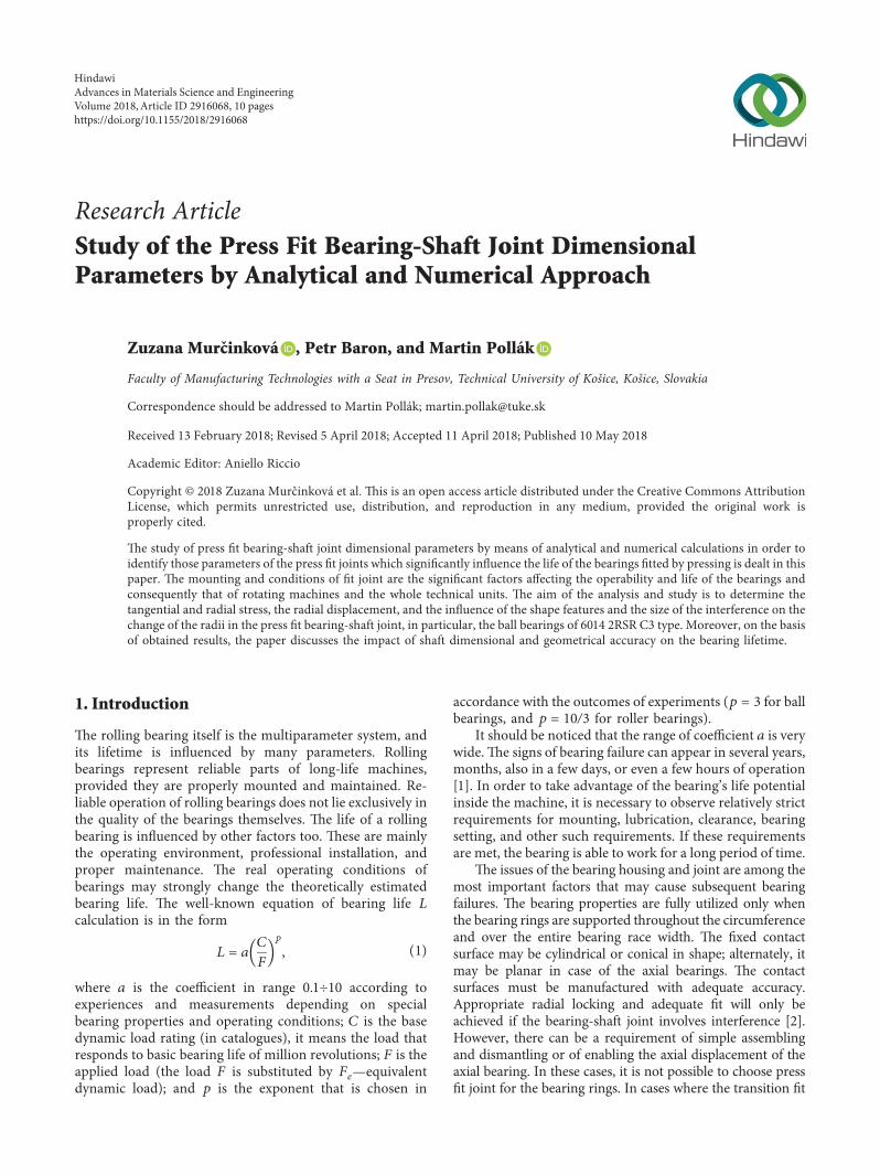

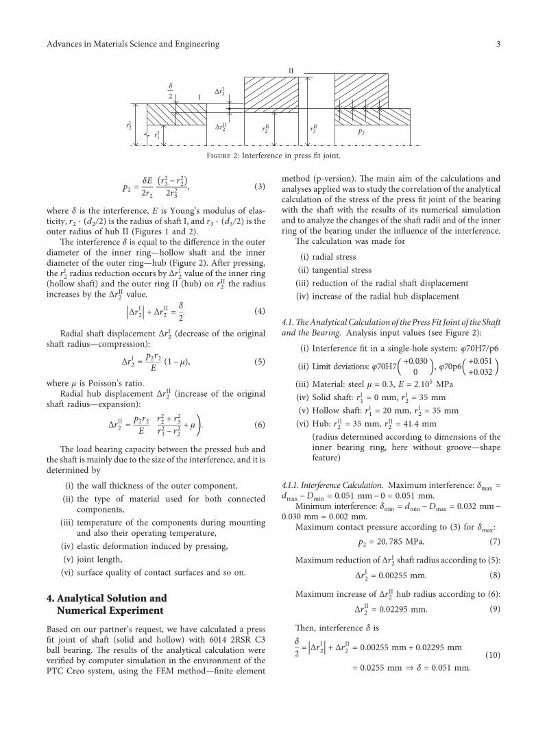
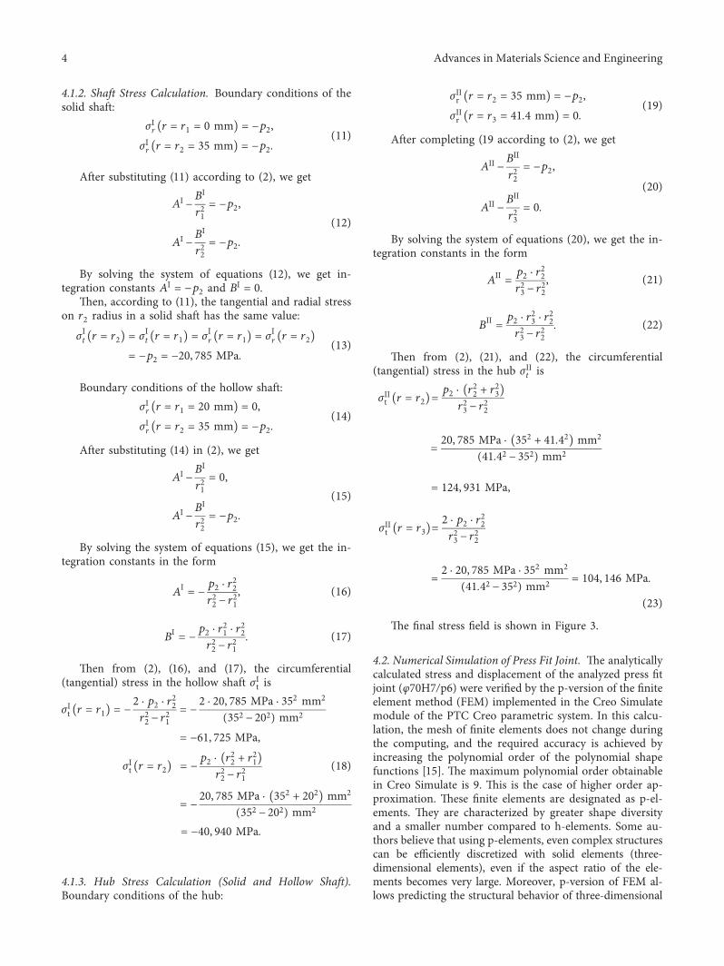
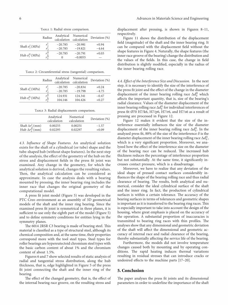


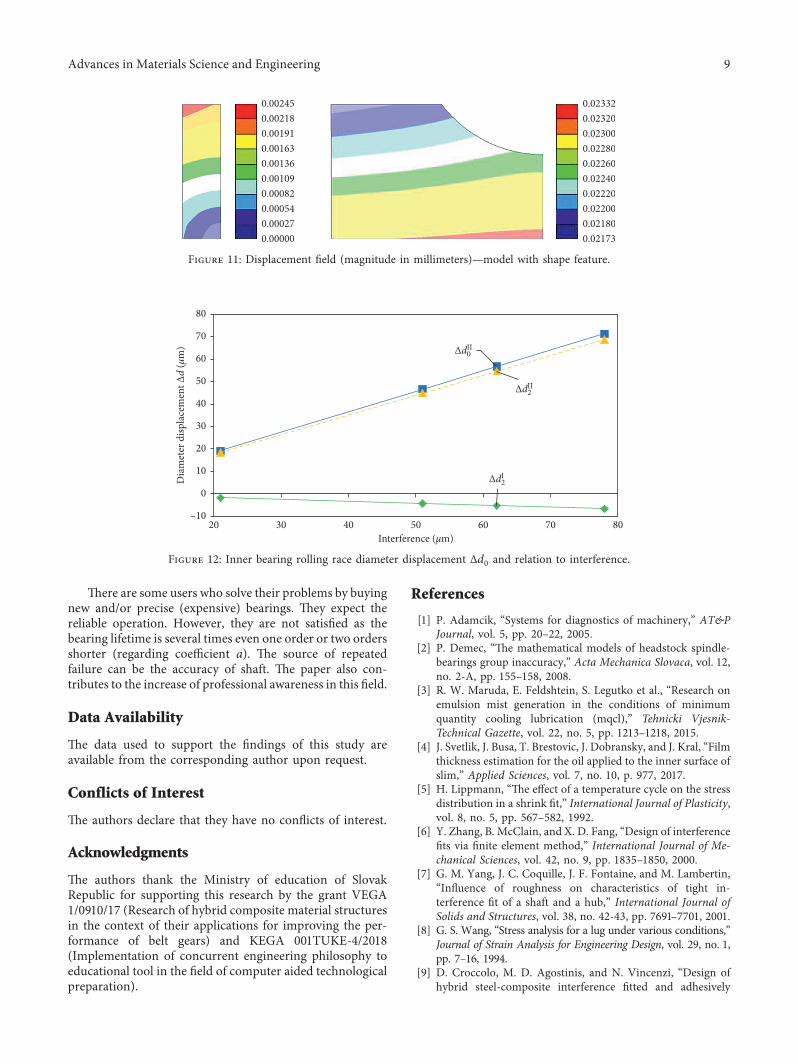


![FatigueCrack GrowthBehaviourof Nitridedand Shot PeenedSpecimens · In [Croccolo, and etc., 2002] the fatigue strength of a shot-peened nitrided low-alloy steel is investigated and](https://static.documents.pub/doc/80x56/5c66e36409d3f2e33b8cc1a3/fatiguecrack-growthbehaviourof-nitridedand-shot-in-croccolo-and-etc-2002.jpg)


