Abstract: Regarding to the limitations of several existing coal mine Measurement-While-Drilling (MWD) data transmission modes in practical application, this paper aims to achieve the application of the acoustic wave transmission technology in coal mine MWD system by using propagation characteristics of the acoustic wave in the drill pipe so as to make up for the application deficiencies of existing transmission modes in the working condition. In this paper, the attenuation and adaptative frequency of the signal in the drill pipe column are verified by the mathematical analysis of the acoustic wave propagation characteristics in the drill pipe column, the signal sources and communication strategies that meet the conditions of underground coal mine are designed, and the communication effect of the acoustic wave in the drill pipe string is verified through testing MWD data transmission, which proves the feasibility of the data transmission through acoustic wave in underground coal mine.
1. MWD Data Transmission Technology
Due to the advantages of controllable trajectory, rotary hole bottom and great drilling depth, MWD directional drilling has been increasingly used in coal mine gas extraction, prevention and control of water, exploration of the geological structure and abnormal body at home and abroad. As we know, coal mine MWD directional drilling depends on its core system, mine MWD system, whose application foundation and the key technology relies to the data transmission technology between hole-bottom instrument and hole-mouth instrument, which directly decides whether constructors can obta in a t t i tude parameters of the hole bo t tom dr i l l ing t imely and accura te ly .
At present, the MWD system that meets coal mine explosion-proof requirements has three data transmission methods: cable, mud pulse and electromagnetic wave transmission. The comparison of their performances is shown in Table 1. As the mainstream products on the market, cable data transmission system owns its advantages such as high stability, high directional drilling efficiency, while its disadvantage lies in the usage of cable drill pipe for drilling, causing high drilling cost and low drilling efficiency of the compound drilling. Mud pulse data transmission system has the characteristics of long transmission distance, low rate, which can improve the long and deep hole drilling efficiency of compound drilling, however, because of the existence of active components, maintenance of instruments is needed for long-term use. Electromagnetic wave data transmission system possesses characteristics of fast transfer rate, high efficiency for medium-short hole drilling with the cooperation of compound drilling, but transmission distance is limited, and the received signal may easily suffer electromagnetic interference by strata and peripheral equipment, which, to a certain extent, influences system stability. In summary, the existing data transmission modes can be applied to different working conditions, but they cannot completely satisfy all working conditions, such as conventional rotary shallow hole.
3rd International Conference on Advances in Materials, Mechatronics and Civil Engineering (ICAMMCE 2018)
System Stability Sealed Drill Pipe Mud Pump, Active Stratum, Ground
Transmission Distance 0~2km 0~2km 0~1km
As a research hotspot in the field of oil and gas exploration in recent years, MWD data acoustic transmission technology exploits the transmission characteristics of acoustic waves in drill pipe column to transmit the signal from the hole bottom to hole mouth. As shown in Fig. 1, with simple structure and fast signal transmission speed, it also supports the use of rotary drilling of conventional drill pipe, without being influenced by stratum conditions. Although the progress in the field of oil and gas exploration is relatively slow, due to different working conditions, it has great application prospects in the field of coal mine drilling.
Fig. 1. Acoustic transmission principle of MWD data on underground coal mine
2. Analysis of Acoustic Wave Transmission Characteristics in Drill Pipe Column
The drill pipe column is consisted of many single drill pipes connected by screw threads. The two ends of the drill pipe are the male screw and female thread respectively, and the string of pipes connected to each other constitutes the drill pipe column with periodic structure.
In order to explore the acoustic wave propagation in the drill pipe column, the ideal condition of drill pipe column structure (assuming the screw threads are closely connected with no cracks) is established, and the characteristics of acoustic wave propagation in the drill pipe column are analyzed through the establishment of mathematical model based on the above structure model.
There are three different acoustic wave propagation forms in the drill pipes: bending wave, transverse wave and longitudinal wave. Bending wave transmits very slowly, and can be easily dispersed and attenuated, which goes against signal transmission. While the wave lengths of the longitudinal wave and the transverse wave are longer than the normal diameter of the tubing string, these waves cannot easily scatter during transmission, instead, they reflect at each interface position. Since transverse wave generates more reflection and thus more attenuation at each interface position than longitudinal wave does, it produces relatively inaccurate transmission results. Therefore, longitudinal wave is applied to information transmission.
Advances in Engineering Research, volume 162
203
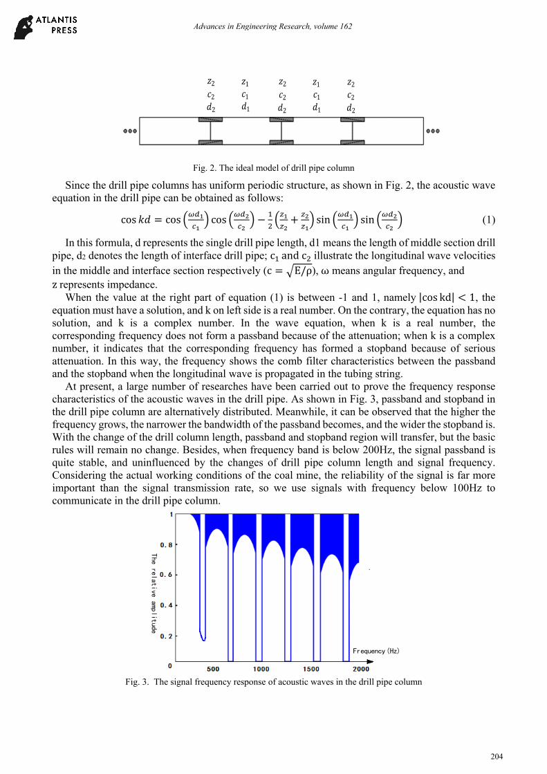
Fig. 2. The ideal model of drill pipe column
Since the drill pipe columns has uniform periodic structure, as shown in Fig. 2, the acoustic wave equation in the drill pipe can be obtained as follows:
cos 𝑘𝑑 cos cos sin sin (1)
In this formula, d represents the single drill pipe length, d1 means the length of middle section drill pipe, d2 denotes the length of interface drill pipe; c and c illustrate the longitudinal wave velocities in the middle and interface section respectively (c E/ρ), ω means angular frequency, and z represents impedance.
When the value at the right part of equation (1) is between -1 and 1, namely |cos kd| 1, the equation must have a solution, and k on left side is a real number. On the contrary, the equation has no solution, and k is a complex number. In the wave equation, when k is a real number, the corresponding frequency does not form a passband because of the attenuation; when k is a complex number, it indicates that the corresponding frequency has formed a stopband because of serious attenuation. In this way, the frequency shows the comb filter characteristics between the passband and the stopband when the longitudinal wave is propagated in the tubing string.
At present, a large number of researches have been carried out to prove the frequency response characteristics of the acoustic waves in the drill pipe. As shown in Fig. 3, passband and stopband in the drill pipe column are alternatively distributed. Meanwhile, it can be observed that the higher the frequency grows, the narrower the bandwidth of the passband becomes, and the wider the stopband is. With the change of the drill column length, passband and stopband region will transfer, but the basic rules will remain no change. Besides, when frequency band is below 200Hz, the signal passband is quite stable, and uninfluenced by the changes of drill pipe column length and signal frequency. Considering the actual working conditions of the coal mine, the reliability of the signal is far more important than the signal transmission rate, so we use signals with frequency below 100Hz to communicate in the drill pipe column.
The
relative
amplit
ude
Frequency(Hz)
Fig. 3. The signal frequency response of acoustic waves in the drill pipe column
𝑑2 𝑑1 𝑑2 𝑑1 𝑑2
𝑐1𝑐2 𝑐1𝑐2 𝑐2
𝑧1 𝑧2 𝑧1 𝑧2 𝑧2
Advances in Engineering Research, volume 162
204
3. Design of Signal Source
To transmit signals by acoustic wave propagation in drill pipe columns, a reliable signal acoustical generator, namely, signal source is required. Combining with the latest research achievements of magnetostrictive materials, we adopt giant magnetostrictive alloy as the core material to design the signal source suitable for the coal mine working environment. Its structure is shown in Fig. 4.
The locking bolt and the belleville spring exert certain prestress on the giant magnetostrictive alloy, which can produce more deformation under compressive stress. The excitation coil is used to exert the excitation current signal to produce alternating magnetic field. As the driving element of transducer, and in the variational magnetic field environment, giant magnetostrictive material produces stretching vibration, which drives the knocking block to generate vibration and radiate acoustic waves. Thus, knocking block is the final output element.
Fig. 4. The vocal structure of the signal source
The performance of signal source depends on the cooperation of mechanical parameters of the sound structure and the driving circuit. In order to meet the requirements, the driving circuit should possess two properties: (1) the emission power is large enough to enhance the radiative energy of the acoustic signal, and increase the transmission distance; (2) the frequency should be appropriate, because over-high frequency will cause more attenuation during the propagation in the pipe string, and over-low frequency will reduce the signal transmission rate. Either will degrade the performance of data transmission. Driving circuit designed based on the above two properties is shown in Fig. 5, which is divided into four parts: power supply circuit, DC high voltage source, synchronous control circuit and transmission circuit.
Fig.5. The structure diagram of the acoustic generator driving circuit
The power supply circuit provides DC input electric energy, which can be provided by the battery and input into the DC high voltage source circuit, then, high voltage pulsating direct current is obtained through boosting by push-pull converter. The transmitting circuit energy storage element is charged by the pulsating current. When the external signal is triggered and the circuit is synchronously controlled, the pulse current with adjustable width can be obtained. External trigger signal, resulting from pulse control signal modulated by MWD data, together with synchronous control circuit controls capacitor discharge of the transmission circuit through turning on and off the power tube of the drive switch so as to achieve the purpose of short-time pulse voltage output, namely, the control of knocking motion.
Advances in Engineering Research, volume 162
205
4. Data Transmission Experiment
In order to accurately test the acoustic transmission effect of MWD data, a test platform as Fig. 6 is set up, and the drill pipe column is composed of 30 external flat drill pipes with the size of φ73mm 1m. The sending computer randomly sends a set of MWD data (dip angle, azimuth angle, tool face angle). After signal conversion, the signal source knocks in accordance with the established way and acoustic signals generated are transmitted vertically along the drill pipe column; at the other end, vibration sensors convert the received acoustic signal in the drill pipe into voltage signal, which is then sent to the acquisition circuit filter for enlargement and demodulation. The demodulated results are uploaded to the receiving computer to display the data. By comparing the sending and received data of two computers, we can get the effect of MWD data transmission.
Signal Source
Drill Column
Vibration Sensor
Signal Conversion
Computer (Send)
Computer (Receive)
Signal Acquisition
Fig.6. The connection of the experiment
Before testing the data transmission effect, it is necessary to determine the driving current value and pulse width of the signal source so as to achieve the best transmission effect. Different pulse current peaks can be obtained by varying the capacitance capacity of the transmission circuit. The tested current peaks of the output pulse of the driving power here are 1A and 1.5A respectively. And the width of the pulse starts at 5μs till it goes up to 100 μs and it increases progressively per 5μs. The relationship curve of pulse width and output amplitude is shown in Fig. 7. (a) Pulse current with peak of 1.5A. (b) Pulse current with peak of 1A. From Fig. 7, it can be seen that with the increase of pulse width, the output amplitude of the signal source presents linear increase. When the pulse width increases to a certain value, the output amplitude increment of the signal source is not very obvious, and it approximates to a straight line. It can also be seen from the figure that the maximum amplitude of 1.5A pulse current excitation is obviously higher than that of 1A pulse current, and it enters into the saturated zone of magnetostrictive materials when the pulse width is relatively small. Therefore, we adopt 50μs pulse width and 1.5A drive current to stimulate the vibration of giant magnetostrictive alloy to generate the acoustic signal. In addition, in order to avoid interference of residual vibration, when the external trigger signal is modulating signals, it is necessary to increase the pulse width of the modulation signal to more than 10ms to test MWD acoustic transmission data.
(a)Pulse current with peak of 1.5A
Advances in Engineering Research, volume 162
206
(b)Pulse current with peak of 1A
Fig.7. The relationship curve of pulse width and output amplitude
When experiment equipment was connected and the parameters were set according to Fig. 6, sets of MWD data were sent hundreds of times irregularly, then transmission effect of MWD data was checked on the receiving computer. In Table 2, only three groups of typical data received were listed. When the data was received through single channel, the inaccuracy rate is between 1% and 2%; while dual channels mean two groups of vibration sensors both collect signals at the receiver end, and they verify each other so that reliable data can be obtained. Thus, the inaccuracy rate is 0.
5. Conclusion
Based on the above theory and experimental verification, we can see that it is completely feasible for coal mine MWD system to use acoustic wave to carry out low-frequency data transmission and giant magnetostrictive alloy materials to design signal source, which can basically overcome problems such as signal attenuation, stopband alternates in drill pipe columns and residual vibration. It can also solve the transmission distance and structural design problems of conventional rotary drill. However, actual working conditions are far more complexed and severe than our experiment conditions, therefore, further experiments still need to be done under more complexed test conditions, for example, there’s water inside and outside the pipe columns, the closeness of drill pipe columns are different, and transmission length increases, etc..
Table 2. Experiment Record of Data Transmission
project irregular
data
data received through single channel data received through dual channels
1 2 3 inaccuracy
rate1 2 3
inaccuracy rate
dip angle /° (-90.0~90.0)
5.5 5.5 5.5 / 1% 5.5 5.5 5.5 0
azimuth angle /° (0.0~360.0)
135.3 135.3 / 153.2 2% 135.3 135.3 135.3 0
tool face angle /° (0.0~360.0)
269.9 269.9 269.9 / 1% 269.9 269.9 269.9 0
References
[1] Gao Jun. Research on Data Transmission Technology in Mine MWD Systems [J]. Zhongzhou Coal, vol.4, pp. 115-117+121, 2016.
[2] Wasserman, Ingolf,Hahn, Detlef, Nguyen, Dang Hai,Reckmann, Hanno,Macpherson, John. Mud-pulse telemetry sees step-change improvement with oscillating shear valves [J]. Oil & Gas Journal, vol.24, pp. 106-109, 2008.
[3] Ya Yuan. Structure Design and Performance Optimi- zation of rare earth Magnetostrictive Transducer [D]. Xiangtan University, 2013.
Advances in Engineering Research, volume 162
207
[4] Wei Yang. Optimization and Applications of Rare Earth Gaint Magnetostrictive Transducer Drive Power [D]. Xiangtan University, 2011.
[5] Akkaya Y, Voigt T, Subramaniam K V, et al. Nondestructive measurement of concrete strength gain by an ultrasonic wave reflection method [J]. Materials & Structures, vol. 8, pp. 507-514, 2003.
[6] Zou B, Yu Y, Huang X, et al. All-Optical Format Conversion for Multichannel QPSK Signals [J]. Journal of Lightwave Technology, vol.3, pp. 375-384, 2012.
[7] He Yanxia. Research on Detection Technology of Downhole Acoustic Transmission Signal [D]. Xi’an Shiyou University, 2013.
[8] Li Chao. The Research and Development of MWD Data Acoustic Transmission Technology Based on Drill Pipe [D]. China University of Petroleum, 2010.
[9] Gao L, Gardner W R, Robbins C, et al. Limits on Data Communication along the Drillstring Using Acoustic Waves [J]. Spe Reservoir Evaluation & Engineering, vol.1, pp. 141-146, 2008.
[10] GAO L,GARDNER W, etal. Acoustic telemetry can deliver more real-time downhole data in underbalanced drilling operations [C]. SPE/IADC Drilling Conference, 2006.
[11] Neff J, Camwell P. Field-Test Results of an Acoustic MWD System[C]. SPE/IADC Drilling Conference, 2007.
[12] Vimal S, Wallace G, Johnson D H, et al. Design Considerations for a New High Data Rate LWD Acoustic Telemetry System[C]. Society of Petroleum Engineers, 2004.
[13] Shang H, Zhou J, Yan B. On Simulation of Acoustic Drill String Channel and Information Transmission [J]. Well Logging Technology, 2015.
[14] Ustun B, Avci K. A New hybrid window based on Cosh and Hamming windows for nonrecursive digital filter design[C]. Signal Processing and Communications Applications Conference, 2015.
[15] Che X H, Qiao W X, Jun L I, et al. Acoustic spectral characteristics of drill string of logging while drilling [J]. Journal of China University of Petroleum, vol.6, pp. 66-70, 2008.