Study on Dynamic Characteristics of Hydraulic Pumping Unit onOffshore PlatformCHANG Zong-yua, YU Yan-quna, b, *, QI Yao-guangbaCollege of Engineering, Ocean University of China, Qingdao 266100, ChinabCollege of Mechanical and Electronic Engineering, China University of Petroleum, Qingdao 266580, China
Received February 22, 2017; revised April 26, 2017; accepted June 22, 2017
AbstractA new technology of offshore oil rod pumping production is developed for offshore heavy oil recovery. A new typeof miniature hydraulic pumping unit with long-stroke, low pumping speed and compact structure is designed basedon the spatial characteristics of offshore platforms. By combining the strengths of sinusoidal velocity curve andtrapezoidal velocity curve, a kinematical model of the acceleration, the velocity and displacement of the pumpingunit’s hanging point is established. The results show that the pumping unit has good kinematic characteristics ofsmooth motion and small dynamic load. The multi-degree-of-freedom dynamic model of the single-well pumpingunit is established. The first and second order natural frequencies of the sucker rod string subsystem and the pumpingunit subsystem are studied. The results show that the first and the second order natural frequencies among thepumping rod string, pumping unit-platform subsystem and the dynamic excitation have differences over 5 times fromeach other, indicating that resonance phenomenon will not appear during the operation and the dynamic requirementsfor field use are met in the system.Key words: offshore platform, platform pumping unit, kinematic model, dynamic model, multiple degrees of freedom
Citation: Chang, Z. Y., Yu, Y. Q., Qi, Y. G., 2017. Study on dynamic characteristics of hydraulic pumping unit on offshore platform. ChinaOcean Eng., 31(6): 693–699, doi: 10.1007/s13344-017-0079-1
1 Introduction25% of the proved reserves and 45% of the ultimate re-
coverable reserves on earth are ascertained from the ocean.The future focus of the world’s oil production will gradu-ally shift from onshore to offshore (Terdre, 2011; Shariatin-ia et al., 2013; Dev et al., 2016). The main producing areasof Chinese offshore oilfield have transited from the north-ern oil fields of the South China Sea in the last century tothe Bohai oilfield nowadays (Guo et al., 2010). Currently,proved oil reserves with viscosity above 350 MPa·s in theBohai Bay region are over 7.41×10⁸ t and un-producingproved reserves reach up to 6.5×10⁸ t, which accounts for87.3% of the total (Li et al., 2016). Therefore, research onthe high-efficient development of offshore heavy oil occu-pies a pivotal position in the reserve discovery and recov-ery, productivity construction and oilfield production in theBohai Bay region.
Steam stimulation, of easy operation, quick results, wideapplication to various types of heavy oil reservoirs, is thecurrent main technology for heavy oil production. Owing tothe limitation of the platform space, electric submersible
pump is the main lifting equipment of offshore oil recovery(Dong et al., 2008). The pump units and the cables have lowtemperature resistance, which will influence the implanta-tion temperature and dryness of the steam, thereby affectingthe stimulation effect. Thus, a new method of artificial lift-ing is urgently needed to meet the requirement of high-effi-cient development of offshore heavy oil (Yu et al., 2016).The structure and performance of the platform pumping unitare the key points in the offshore rod pumping productionsystem. The structure of the pumping unit is mainly de-scribed in this paper. The kinematic and dynamic perform-ances of the pumping unit are emphatically studied.
2 Design of the hydraulic pumping unit for the offshoreplatformThe target offshore platform is located in LD27-2 oil-
field in the eastern Bohai Sea. The platform is divided intofive decks. The height of the bottom deck, middle deck andtop deck is 5 m, and the distance between the platform well-heads is 1.8 m×2.0 m. The work area of the offshore pump-ing unit is shown in Fig. 1.
China Ocean Eng., 2017, Vol. 31, No. 6, P. 693–699DOI: 10.1007/s13344-017-0079-1, ISSN 0890-5487http://www.chinaoceanengin.cn/ E-mail: [email protected]
Foundation item: This work was financially supported by the National Natural Science Foundation of China (Grant No. 51174224), the National Scienceand Technology Major Projects of Oil and Gas (Grant Nos. 2016ZX05066 and 2016ZX05042), and the Natural Science Foundation of ShandongProvince (Grant No. ZR2014El015).*Corresponding author. E-mail: [email protected]
Because of the wellhead space constraints and workover operations’ requirement, the new hydraulic pumpingunit on the offshore platform must be of compact structureand small occupied area. The current design of the smallland-use hydraulic pumping unit is shown in Fig. 2a. Theuse of the two-stage telescopic hydraulic cylinder can re-duce the height of the pumping unit with a single-stage hy-draulic cylinder by half and the whole mass of the unit isaround 800 kg. The unit can meet the need of 5-meter strokeon the offshore platform. The overall structure is shown inFig. 2b.
3 Research on kinematics of hydraulic pumping unit onoffshore platformThe speed curve of the pumping unit can be designed as
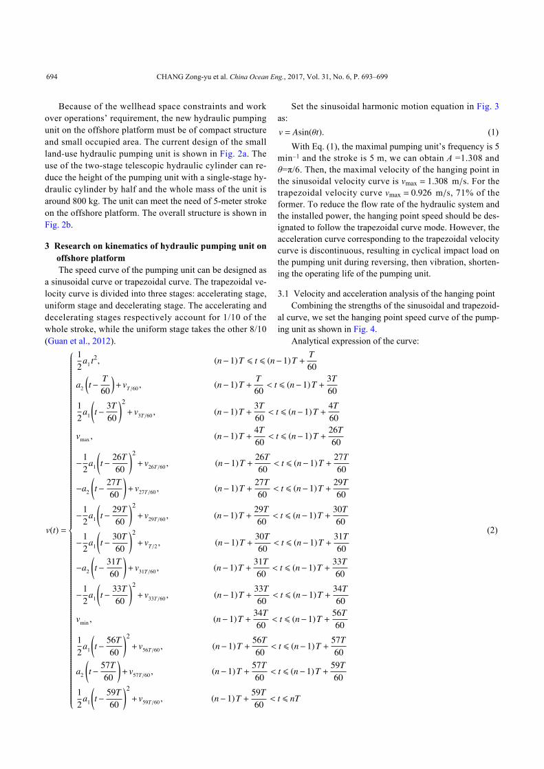
a sinusoidal curve or trapezoidal curve. The trapezoidal ve-locity curve is divided into three stages: accelerating stage,uniform stage and decelerating stage. The accelerating anddecelerating stages respectively account for 1/10 of thewhole stroke, while the uniform stage takes the other 8/10(Guan et al., 2012).
Set the sinusoidal harmonic motion equation in Fig. 3as:v = Asin(θt). (1)
vmax = 1.308 m/svmax = 0.926 m/s
With Eq. (1), the maximal pumping unit’s frequency is 5min–1 and the stroke is 5 m, we can obtain A =1.308 andθ=π/6. Then, the maximal velocity of the hanging point inthe sinusoidal velocity curve is . For thetrapezoidal velocity curve , 71% of theformer. To reduce the flow rate of the hydraulic system andthe installed power, the hanging point speed should be des-ignated to follow the trapezoidal curve mode. However, theacceleration curve corresponding to the trapezoidal velocitycurve is discontinuous, resulting in cyclical impact load onthe pumping unit during reversing, then vibration, shorten-ing the operating life of the pumping unit.
3.1 Velocity and acceleration analysis of the hanging pointCombining the strengths of the sinusoidal and trapezoid-
al curve, we set the hanging point speed curve of the pump-ing unit as shown in Fig. 4.
Analytical expression of the curve:
v(t) =
12
a1 t2, (n−1)T ⩽ t ⩽ (n−1)T +T60
a2
(t− T
60
)+ vT/60 , (n−1)T +
T60< t ⩽ (n−1)T +
3T60
12
a1
(t− 3T
60
)2
+ v3T/60 , (n−1)T +3T60< t ⩽ (n−1)T +
4T60
vmax , (n−1)T +4T60< t ⩽ (n−1)T +
26T60
−12
a1
(t− 26T
60
)2
+ v26T/60 , (n−1)T +26T60< t ⩽ (n−1)T +
27T60
−a2
(t− 27T
60
)+ v27T/60 , (n−1)T +
27T60< t ⩽ (n−1)T +
29T60
−12
a1
(t− 29T
60
)2
+ v29T/60 , (n−1)T +29T60< t ⩽ (n−1)T +
30T60
−12
a1
(t− 30T
60
)2
+ vT/2 , (n−1)T +30T60< t ⩽ (n−1)T +
31T60
−a2
(t− 31T
60
)+ v31T/60 , (n−1)T +
31T60< t ⩽ (n−1)T +
33T60
−12
a1
(t− 33T
60
)2
+ v33T/60 , (n−1)T +33T60< t ⩽ (n−1)T +
34T60
vmin , (n−1)T +34T60< t ⩽ (n−1)T +
56T60
12
a1
(t− 56T
60
)2
+ v56T/60 , (n−1)T +56T60< t ⩽ (n−1)T +
57T60
a2
(t− 57T
60
)+ v57T/60 , (n−1)T +
57T60< t ⩽ (n−1)T +
59T60
12
a1
(t− 59T
60
)2
+ v59T/60 , (n−1)T +59T60< t ⩽ nT
(2)
694 CHANG Zong-yu et al. China Ocean Eng., 2017, Vol. 31, No. 6, P. 693–699
ai(i = 1,2)where, T is the period of the pumping unit (s); n is naturalnumber; is the velocity coefficient.
3.2 Solution of the hanging point kinematic characteristicsWith the pumping unit’s frequency of 5 min–1(i.e. T=12
s), and stroke L=5 m, we have:6∫0
v(t)tdt = 5;12∫0|v(t)t|dt = 10. (3)
a1 = 8.013 a2 = 1.603With the simultaneous Eqs. (2) and (3), the solution:
, .The acceleration equation of the pumping unit is:
a(t)=
a1 t, 6(n−1) ⩽ t ⩽ 6(n−1)+0.2a2 , 6(n−1)+0.2 < t ⩽ 6(n−1)+0.6a2 −a1 (t−0.6) , 6(n−1)+0.6 < t ⩽ 6(n−1)+0.80, 6(n−1)+0.8 < t ⩽ 6(n−1)+5.2−a1 (t−5.2) , 6(n−1)+5.2 < t ⩽ 6(n−1)+5.4−a2 , 6(n−1)+5.4 < t ⩽ 6(n−1)+5.8a1 (t−5.8)−a2, 6(n−1)+5.8 < t ⩽ 6n
(4)The hanging point of the pumping unit has a continuous
acceleration curve, which effectively reduces the impact ofthe load on the pumping unit and improves its stability. Theacceleration period is 6 s and the maximum acceleration is
1.603 m/s2. The acceleration value is small, indicating thatthe pumping unit runs smoothly with small dynamic load.The pumping speed period is 12 s and the maximum velo-city is 0.962 m/s, which is 73.5% of the maximum velocityin sinusoidal curve as shown in Fig. 3.
4 Dynamics study on offshore platform hydraulicpumping unitThe Structure of offshore platform–hydraulic pumping
unit–sucker rod string system is shown in Fig. 5.The oil recovery system shown in Fig. 5 can be divided
into two subsystems: the sucker rod string system and thepumping unit-platform support system.
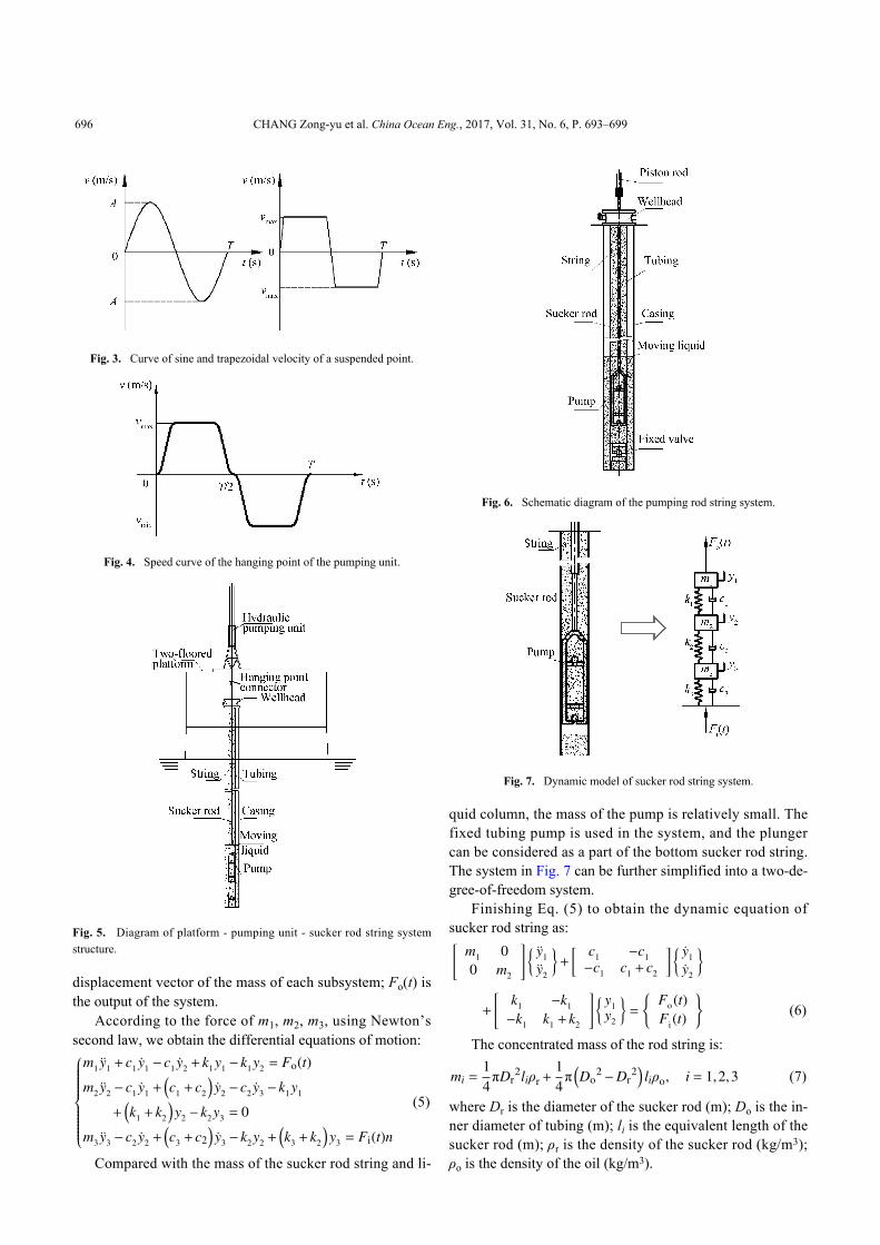
4.1 Dynamic analysis of sucker rod string systemIn the pumping unit prediction models, the method of
solving the wave equation of the sucker rod string is mostlyused, which has a huge work load. The mechanical systemof mass-spring-damping as the dynamic model to describethe longitudinal vibration of the sucker rod is the trend (Li,X.Y. et al., 2016; Zhang, 2007). The structure of the suckerrod string is shown in Fig. 6.
The oil sucker rod strings are separated into n mass-con-centrated and spring components, and the correspondingstrings can form n mass-spring-damping sub-systems.
4.1.1 Dynamic model of sucker rod systemTarget well LD27-2-A22H is with the vertical depth of
1180 m, primary sucker rod diameter of 19 mm, verticaldepth of 420 m; secondary sucker rod diameter of 22 mm,vertical depth of 760 m. The simplest kinetic model for thesucker rod string can apply the two-degree-of-freedom sys-tem simulation; and the entire rod string system can be ana-lyzed with three-degree-of-freedom. The dynamic model isshown in Fig. 7.
In Fig. 7, Fi(t) is the input of the system; mi (i=1, 2, 3) isthe concentrated mass of each subsystem; ki (i=1, 2, 3) is theequivalent stiffness of each subsystem; ci (i=1, 2, 3) is theequivalent damping of each subsystem; yi (i=1, 2, 3) is the
Fig. 1. Schematic diagram of the working area of the
target offshore platform.
Fig. 2. Hydraulic pumping unit in the onshore and offshore oilfield.
CHANG Zong-yu et al. China Ocean Eng., 2017, Vol. 31, No. 6, P. 693–699 695
displacement vector of the mass of each subsystem; Fo(t) isthe output of the system.
According to the force of m1, m2, m3, using Newton’ssecond law, we obtain the differential equations of motion:
m1 y1 + c1 y1 − c1 y2 + k1y1 − k1y2 = Fo(t)
m2 y2 − c1 y1 +(c1 + c2
)y2 − c2 y3 − k1y1
+(k1 + k2
)y2 − k2 y3 = 0
m3 y3 − c2 y2 +(c3 + c2
)y3 − k2y2 +
(k3 + k2
)y3 = Fi(t)n
(5)
Compared with the mass of the sucker rod string and li-
quid column, the mass of the pump is relatively small. Thefixed tubing pump is used in the system, and the plungercan be considered as a part of the bottom sucker rod string.The system in Fig. 7 can be further simplified into a two-de-gree-of-freedom system.
Finishing Eq. (5) to obtain the dynamic equation ofsucker rod string as:[
m1 00 m2
]{ y1
y2
}+
[ c1 −c1−c1 c1 + c2
]{ y1
y2
}+
[k1 −k1
−k1 k1 + k2
]{ y1y2
}=
{Fo (t)Fi (t)
}(6)
The concentrated mass of the rod string is:
mi =14πDr
2liρr+14π(Do
2−Dr2)liρo, i = 1,2,3 (7)
where Dr is the diameter of the sucker rod (m); Do is the in-ner diameter of tubing (m); li is the equivalent length of thesucker rod (m); ρr is the density of the sucker rod (kg/m3);ρo is the density of the oil (kg/m3).
Fig. 3. Curve of sine and trapezoidal velocity of a suspended point.
Fig. 4. Speed curve of the hanging point of the pumping unit.
Fig. 5. Diagram of platform - pumping unit - sucker rod string systemstructure.
Fig. 6. Schematic diagram of the pumping rod string system.
Fig. 7. Dynamic model of sucker rod string system.
696 CHANG Zong-yu et al. China Ocean Eng., 2017, Vol. 31, No. 6, P. 693–699
Equivalent stiffness:
ki =EAi
li=
14πDi
2 Eli, (8)
where, E is the elastic modulus of the rod material, 210GPa; Ai is the sucker rod cross-sectional area (m2).
Equivalent damping (Zhan and Wang, 1984):
Ci =2πμρrAr
1lnm+
4B2
(B1+1)
B1+
2a(sin
ωLa+ cos
ωLa
)ωL
(9)
μwhere is the average viscosity of the liquid (MPa·s); ρr isthe density of sucker rod (kg/m3); Ar is the cross-sectional
area of sucker rod, (m2); a is the propagation velocity ofstress wave (m/s); ω is the angular velocity converted intothe crank (rad/s); L is the length of sucker rod (m).
m =D0
Dr; B1 =
m2−12lnm
−1; B2 = m4−1−
(m2−1
)2
lnm.
4.1.2 Natural frequency of the rod string systemThe characteristic matrix equation of the sucker rod
string system of Eq. (6) is:∣∣∣∣K−ω2n j M
∣∣∣∣= ∣∣∣∣∣∣[
k1 −k1
−k1 k1 + k2
]−ωn j
2[
m1 00 m2
]∣∣∣∣∣∣= 0 (10)
By solving Eq. (10), the first- and second-order naturalfrequencies of the system are:
ωn1,2 =
√√√√√√k1m2 +
(k1 + k2
)m1
2m1m2
∓ 12
√√√√k1m2 +(k1 + k2
)m1
m1m2
2
−4k1k2
m1m2
. (11)
ωn1 = 2.858 s−1
ωn2 = 8.942 s−1
The concentrated mass m1=6.691×10³ kg, the equival-ent stiffness k1=1.050×10⁵ N/m; the concentrated massm2=3.407×10³ kg, and the equivalent stiffness k2=1.418×10⁵N/m. From Eq. (11) respectively, we have the first-ordernatural frequency , and the second-order fre-quency .
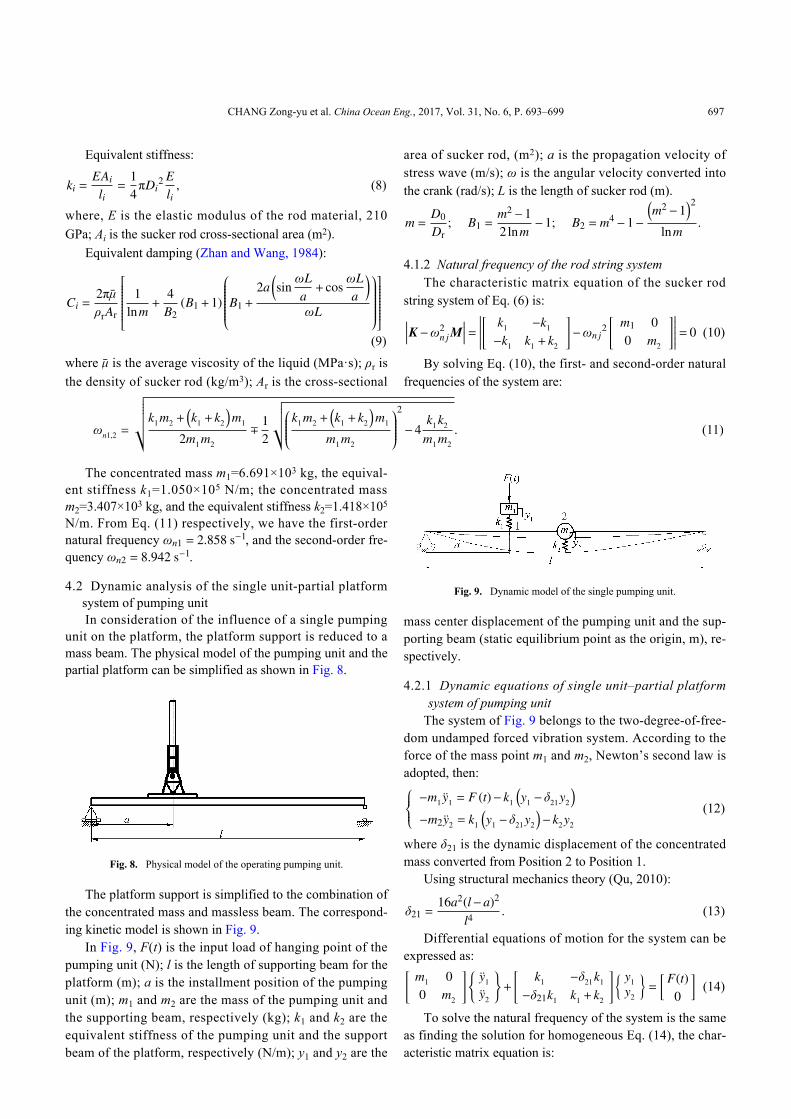
4.2 Dynamic analysis of the single unit-partial platformsystem of pumping unitIn consideration of the influence of a single pumping
unit on the platform, the platform support is reduced to amass beam. The physical model of the pumping unit and thepartial platform can be simplified as shown in Fig. 8.
The platform support is simplified to the combination ofthe concentrated mass and massless beam. The correspond-ing kinetic model is shown in Fig. 9.
In Fig. 9, F(t) is the input load of hanging point of thepumping unit (N); l is the length of supporting beam for theplatform (m); a is the installment position of the pumpingunit (m); m1 and m2 are the mass of the pumping unit andthe supporting beam, respectively (kg); k1 and k2 are theequivalent stiffness of the pumping unit and the supportbeam of the platform, respectively (N/m); y1 and y2 are the
mass center displacement of the pumping unit and the sup-porting beam (static equilibrium point as the origin, m), re-spectively.
4.2.1 Dynamic equations of single unit–partial platformsystem of pumping unitThe system of Fig. 9 belongs to the two-degree-of-free-
dom undamped forced vibration system. According to theforce of the mass point m1 and m2, Newton’s second law isadopted, then: −m1 y1 = F (t)− k1
(y1 −δ21 y2
)−m2y2 = k1
(y1 −δ21 y2
)− k2y2
(12)
where δ21 is the dynamic displacement of the concentratedmass converted from Position 2 to Position 1.
Using structural mechanics theory (Qu, 2010):
δ21 =16a2(l−a)2
l4. (13)
Differential equations of motion for the system can beexpressed as:[
m1 00 m2
]{y1
y2
}+
[k1 −δ21 k1
−δ21k1 k1 + k2
]{ y1y2
}=
[ F(t)0
](14)
To solve the natural frequency of the system is the sameas finding the solution for homogeneous Eq. (14), the char-acteristic matrix equation is:
Fig. 8. Physical model of the operating pumping unit.
Fig. 9. Dynamic model of the single pumping unit.
CHANG Zong-yu et al. China Ocean Eng., 2017, Vol. 31, No. 6, P. 693–699 697
∣∣∣∣K−ω2n j M
∣∣∣∣ = ∣∣∣∣∣∣[
k1 −δ21 k1
−δ21 k1 k1 + k2
]−ω2
n j
[m1 0.0 m2
]∣∣∣∣∣∣ = 0. (15)
Therefore, the natural frequency of the system is:
ωn1,2 =
√√√√√√k1m2 +
(k1 + k2
)m1
2m1m2
∓ 12
√√√√k1m2 +(k1 + k2
)m1
m1m2
2
−4k1
(k1 + k2
)−δ2
21k21
m1 m2
. (16)
4.2.2 Natural frequency of the single unit- partial platformsystem of the pumping unitThe supporting structure of the pumping unit is simpli-
fied as the series spring system shown in Fig. 10 to solve theequivalent stiffness of the pumping unit support. The forcesegment of the support is divided into Segments 1, 2 and 3.Set the stiffness respectively as kz1, kz2, kz3, and the basestiffness as kz4.
Based on Fig. 10, the equivalent stiffness of the supportof the pumping unit satisfies the following formula:1kz=
Under the load of W=10 t, the static deflections of eachequivalent section are respectively δz1 = 0.979 –3m; δz5 =
The equivalent stiffness of each segment is:
kzi =Wδzi, i = 1,2,3,4 (19)
k1 = 0.905×10⁷ N/mTake Eq. (19) into Eq. (18), then the equivalent stiff-
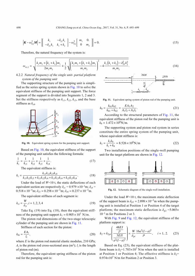
ness of the pumping unit support .The piston rod dimensions of the two-stage telescopic
cylinder of the pumping unit are shown in Fig. 11.Stiffness of each section for the piston:
khi =EAi
li, (20)
where E is the piston rod material elastic modulus, 210 GPa;Ai is the piston rod cross-sectional area (m2); li is the lengthof piston rod (m).
Therefore, the equivalent spring stiffness of the pistonrod for the pumping unit is:
kh =kh1kh2
kh1+ kh2=
EA1A2
A1l2+A2l1. (21)
kh = 1.472×10⁸N/m.
According to the structural parameters of Fig. 11, theequivalent stiffness of the piston rod for the pumping unit is
The supporting system and piston rod system in seriesconstitute the entire spring system of the pumping unit,whose equivalent stiffness is:
k1 =kzkh
kz+ kh= 8.526×10⁶N/m (22)
Two installation positions of the single-well pumpingunit for the target platform are shown in Fig. 12.
δp1 = 2.898×10⁻³m
5.065×
Under the load W=10 t, the maximum static deflectionof the support beam is when the pump-ing unit is installed at Position 1 or Position 4 of the targetplatform; the maximum static deflection is δp2 =10–3 m for Positions 2 or 3.
With Fig. 9 and Fig. 12, the equivalent stiffness of theplatform support is:
k2 = k2pi
48EI
l33EIl
a2(l−a)2
= Wδpi
16a2(l−a)2
l4, i = 1, 2. (23)
×107
×107
Based on Eq. (23), the equivalent stiffness of the plat-form beam is k2=1.703 N/m when the unit is installedat Position 1 or Position 4; The effective stiffness is k2=0.974 N/m for Position 2 or Position 3.
Fig. 10. Equivalent spring system for the pumping unit support.
Fig. 11. Equivalent spring system of piston rod of the pumping unit.
Fig. 12. Schematic diagram of the single-well installation.
698 CHANG Zong-yu et al. China Ocean Eng., 2017, Vol. 31, No. 6, P. 693–699
×103
×106
×103
×107 ×107
With the total unit mass m1=1.266 kg, equivalentstiffness k1=8.526 N/m, the mass of the simplifiedbeam m2=3.248 kg, the equivalent stiffness of the beamk2=1.703 N/m (Position 1 or 4), k2=0.974 N/m(Position 2 or 3). Based on Eq. (16), for Position 1 or Posi-tion 4, the first order natural frequency of the single pump-ing unit is 55.306 s–1, the second order natural frequency is107.443 s–1; for Positions 2 and 3, the first order natural fre-quency of the single pumping unit is 44.024 s–1 and thesecond order natural frequency is 102.078 s–1.
4.3 Study of the hydraulic cylinder excitation impact on thesystemThe pumping unit is connected with the sucker rod
string through the hydraulic cylinder. The working force ofthe hydraulic cylinder is the excitation source of the abovetwo subsystems. In accordance with the requirements of theproduced fluids of the oil well, the pumping speed is 2 to 5times per min, i.e. the excitation frequency is 0.033 to 0.083s–1. The relationship between the subsystems and excitationfrequency is shown in Table 1.
From Table 1, the first and second order natural fre-quencies of the two subsystems and the excitation fre-quency differ by more than 5 times, which means that therewill be no resonance phenomenon in the rod production sys-tem of the offshore platform during the working process.
5 ConclusionA new technology of offshore oil rod pumping produc-
tion is developed for the thermal recovery of offshore heavyoil, and a small, two-stage telescopic hydraulic pumpingunit for the offshore platform is studied. The kinetical mod-el of the hanging point for the pumping unit is established.The maximal acceleration of the pumping unit is 5 min–1,the stroke is 5 m, the maximum velocity of suspension is0.962 m/s, the maximum acceleration is 1.603 m/s2, and theacceleration curve is continuous with small extreme value,indicating that the pumping unit movement is smooth, ofsmall dynamic load. The multi-body dynamics model of thesucker rod string, the pumping unit and platform is estab-lished to study the first- and second-order natural frequen-cies of the two subsystems of the pumping unit-platformand sucker rod string. The results show that the first and thesecond order natural frequencies for the sucker rod string,pumping unit-platform subsystem and the dynamic excita-tion frequency have differences over 5 times from each oth-er, indicating no resonance phenomenon in the rod pump-ing and little dynamic impact on the platform from the unit.
ReferencesDev, B., Samudrala, O. and Wang, J.F., 2016. Characterization of leakrates in thermoplastic barrier valve seals under high static and cyc-lic pressure loads, Journal of Petroleum Science and Engineering,145, 279–289.
Dong, Z.G., Zhang, M.J., Zhang, X. and Pang, X.D., 2008. Study onreasonable choice of electric submersible pump, Acta Petrolei Sin-ica, 29(1), 128–131. (in Chinese)
Guan, D.Y., Wang, X., Li, C., Gao, K.S. and Wei, Z.H., 2012. Analys-is of heavy oil characteristics and densification factors of PLA oil-bearing structures in the water area of Bohai, Petroleum Geologyand Engineering, 26(3), 69–71, 75. (in Chinese)
Guo, Y.H., Zhou, X.H., Li, J.P., Ling, Y.X. and Yang, J.M., 2010.Crude features and origins of the Neogene heavy oil reservoirs inthe Bohai Bay, Oil & Gas Geology, 31(3), 375–380, 385. (inChinese)
Li, P., Liu, Z.L., Zou, J., Liu, H.Y., Yu, J.F. and Fan, Y.T., 2016. In-jection and production project of pilot test on steam huff-puff in oil-field LD27–2, Bohai Sea, Acta Petrolei Sinica, 37(2), 242–247. (inChinese)
Li, X.Y., Gao, X.W., Hou, Y.B. and Wang, H.R., 2016. Coupled dy-namic modeling for polished rod load of beam pumping unit, Journ-al of Northwestern University (Natural Science), 37(9), 1225–1229.(in Chinese)
Ou, Z.G., 2010. Engineering Vibration, second ed., Wuhan UniversityPress, Wuhan. (in Chinese)
Shariatinia, Z., Haghighi, M., Feiznia, S., Alizai, A.H. and Levresse,G., 2013. Hydrocarbon migration in the Zagros Basin, offshore Iran,for understanding the fluid flow in the Oligocene-Miocene carbon-ate reservoirs, Russian Geology and Geophysics, 54(1), 64–81.
Terdre, N., 2011. Peregrino producing heavy oil for Statoil offshoreBrazil, Offshore, 71(12), 36.
Yu, Y.Q., Chang, Z.Y., Qi, Y.G., Xue, X. and Zhao, J.N., 2016. Studyof a new hydraulic pumping unit based on the offshore platform,Energy Science & Engineering, 4(5), 352–360.
Zhang, H.Y., 2007. Dynamics Analysis of Beam Pumping Unit andSucker Rod System, MSc. Thesis, Daqing Petroleum Institute. (inChinese)
Zhang, Q. and Wu, X.D., 1984. Pumping well diagnostic techniqueand its application, Journal of East China Petroleum Institute, 8(2),144–159. (in Chinese)
Table 1 Relationship between the subsystems and excitation frequencySubsystems Hydraulic cylinder Sucker rod string system Position 1 or 4 system Position 2 or 3 system
Frequency (s–1) Excitation frequency I II I II I II0.033–0.083 2.858 8.942 55.306 107.443 44.024 102.078
I: the first-order natural frequency; II: the second-order natural frequency.
CHANG Zong-yu et al. China Ocean Eng., 2017, Vol. 31, No. 6, P. 693–699 699