Page 1
Journal of Engineering Science and Technology Vol. 10, No. 7 (2015) 865 - 877 © School of Engineering, Taylor’s University
865
STUDY ON EMPIRICAL SEISMIC CODAL GUIDELINES FOR MASONRY BUILDINGS IN KOLLAM, KERALA, INDIA
N. S. POTTY1,*, M. SIRAJUDDIN
2
1Department of Civil Engineering,
Mohandas College of Engineering & Technology, Trivandrum - 695544, India 2Department of Civil Engineering, TKM College of Engineering, Kollam, Kerala, India
*Corresponding Author: [email protected]
Abstract
Masonry structures fail miserably due to lateral loads. Recent earthquakes in
India and the world and the resulting losses highlighted the structural inadequacy of masonry buildings to seismic loads. Increase in frequency of
earthquake in Kerala recently and increasing concern motivated the study.
Localized survey at Kollam town in Kerala found that most of the structures
were masonry. Kerala falls in Zones II and III. IS 13828 and IS 4326 provides
masonry structures’ empirical design and construction features which may raise
the earthquake resistance. The study is concerned with the numerical analysis of
brick masonry walls (with and without seismic resistive features) subjected to
dynamic loading with emphasis on their non-linear behaviour. Mechanical
properties of three varieties of brick and three different mix proportion of
mortar were determined. Using the material properties, nonlinear dynamic
analysis of a masonry wall panel was done using ANSYS software and the
ground motion record of Bhuj earthquake. The effect of size and position of openings in the masonry walls, the pier size, provision of lintels and the effect
of mortar on resistance of walls under dynamic loads are discussed and possible
retrofitting measures are suggested to strengthen the masonry brick wall.
Keywords: Localised survey, Masonry structures, Empirical guidelines, Seismic
resistance, Dynamic analysis, Wall model.
1. Introduction
In different parts of world and India the occurrence of high intensity earthquakes
have received more attention recently. The resulting losses have highlighted the
structural inadequacy of buildings to carry seismic loads. The post-earth-
quake surveys have proved that the masonry buildings (compared to other types
of buildings) are most vulnerable and have suffered maximum damages in the
Page 2
866 N. S. Potty and M. Sirajuddin
Journal of Engineering Science and Technology July 2015, Vol. 10(7)
Nomenclatures
CM Cement Mortar
d Door
“g” Gravitational acceleration
GOK Government of Kerala
MW Masonry Wall
ND Not Done
RCC Reinforced Cement Concrete
UNDP United Nations Development Fund
URM Unreinforced Masonry
w Window
past earthquakes [1]. Masonry buildings of brick and stone are superior with
respect to durability, fire and heat resistance and formative effects [1, 2]. Because
of the easy availability of materials, economic reasons and merits mentioned
above this type of construction is employed in the rural, urban and hilly regions. It
is flexible enough to accommodate itself according to the prevailing
environmental conditions. Surveys of the affected areas in past earthquakes in
India like Bhuj in 2001, Chamoli in 1999, Jabalpur in 1997, Killari in 1993,
Uttarkashi in 1991 and Bihar - Nepal 1988 has clearly demonstrated that the
major losses of lives were due to collapse of low strength masonry buildings [1].
Based on these experiences, low strength masonry was advised to be avoided
in seismic zones. The Indian Standards IS 13828 states that inclusion of special
earthquake design and construction features may raise the earth quake resistance
of the masonry structures [3]. This type of construction is treated as non-
engineered construction. The plight is that even after gaining knowledge of
earthquake engineering during the last three decades, a proper method has not
been developed for seismic analysis and design of masonry buildings in spite of
the fact that 90% of the population lives in masonry buildings [1]. Masonry
buildings in India are generally designed on the basis of IS 1905 [4]. The
procedure for seismic analysis and design of masonry buildings has still not
received adequate attention in India. There is an urgent need for assessment of the
present condition of components of the buildings and the strength of materials. IS
4326 [5], IS 13827 [6] and IS 13828 [3] provide guidance on seismic resistant
construction of structures. However, the efficiency of these guidelines has not
been examined in detail. The research reported in this paper covers the following
objectives: (1) The extend of compliance of the buildings in Kollam (as a case
study) to the empirical seismic resistant guidelines in the codes, (2) Examination
of properties of masonry materials (masonry units and mortar), and (3) Evaluation
of the guidelines through a non- linear dynamic analysis of a typical masonry wall
with and without compliance to the guidelines.
2. Literature Review
The empirical seismic provisions in the codes required for preparation of the
questionnaire were identified. The response to the questionnaire will identify the
extent of compliance to the codes. The methods of determining the properties of
masonry units and mortar were identified. The parameters (which are important
Page 3
Study of Empirical Seismic Codal Guidelines for Masonry Buildings in . . . . 867
Journal of Engineering Science and Technology July 2015, Vol. 10(7)
for modelling masonry walls using Finite Element namely compressive strength,
water absorption, modulus of elasticity, Poisson Ratio, density of brick and
mortar) were identified from the review of earlier works.
Studies conducted on seismic events in Kerala indicate that intensity varies
according to region [7]. Their studies revealed that Pathanamthitta, Kottayam,
Alapuzha and Ernakulam districts showed highest value of PGA ranging from
0.234g to 0.278g; which indicates that these regions are more susceptible to high
magnitude earthquakes. It also showed that North and South Kerala regions are of
low seismicity. The vulnerability of Kerala as an earthquake-prone state was
highlighted at a meeting of Government and non-government organizations held
recently in association with UNDP [8]. The density of population is 819 persons
per sq. km which is the second highest density in the country [9]. Jaya and
Remmya [10] carried out seismic micro zonation of Thiruvananthapuram.
Seismic Micro-zonation studies of Kochi are being undertaken by Centre for
Earth Science Studies. The aim is to identify sites prone to ground motion
amplification based on available information on geology, geomorphology,
lineament pattern, soil/ lithology, structural features, earthquakes, etc. [11].
Masonry is the most common type of construction for housing in Kerala.
Walls were of load bearing type. Though stone, cut laterite blocks, clay bricks,
mud blocks with lime mortar or cement mortar were used, in last two decades,
brick wall construction became more popular. The scarcity of good quality clay
has led to alternatives like hollow concrete block, solid concrete blocks,
interlocking blocks, whose their strength varies with manufacturer [12].
When dealing with masonry structures, the most common idealizations of
material behaviour are elastic behaviour, plastic behaviour and nonlinear behaviour.
By adopting a nonlinear analysis instead of a linear analysis, a more comprehensive
insight into the structural response can be obtained, with a higher cost, both in terms
of necessary input data and required knowledge of the analyst [13]. Different
modelling methods are available, depending on the level of accuracy, the simplicity
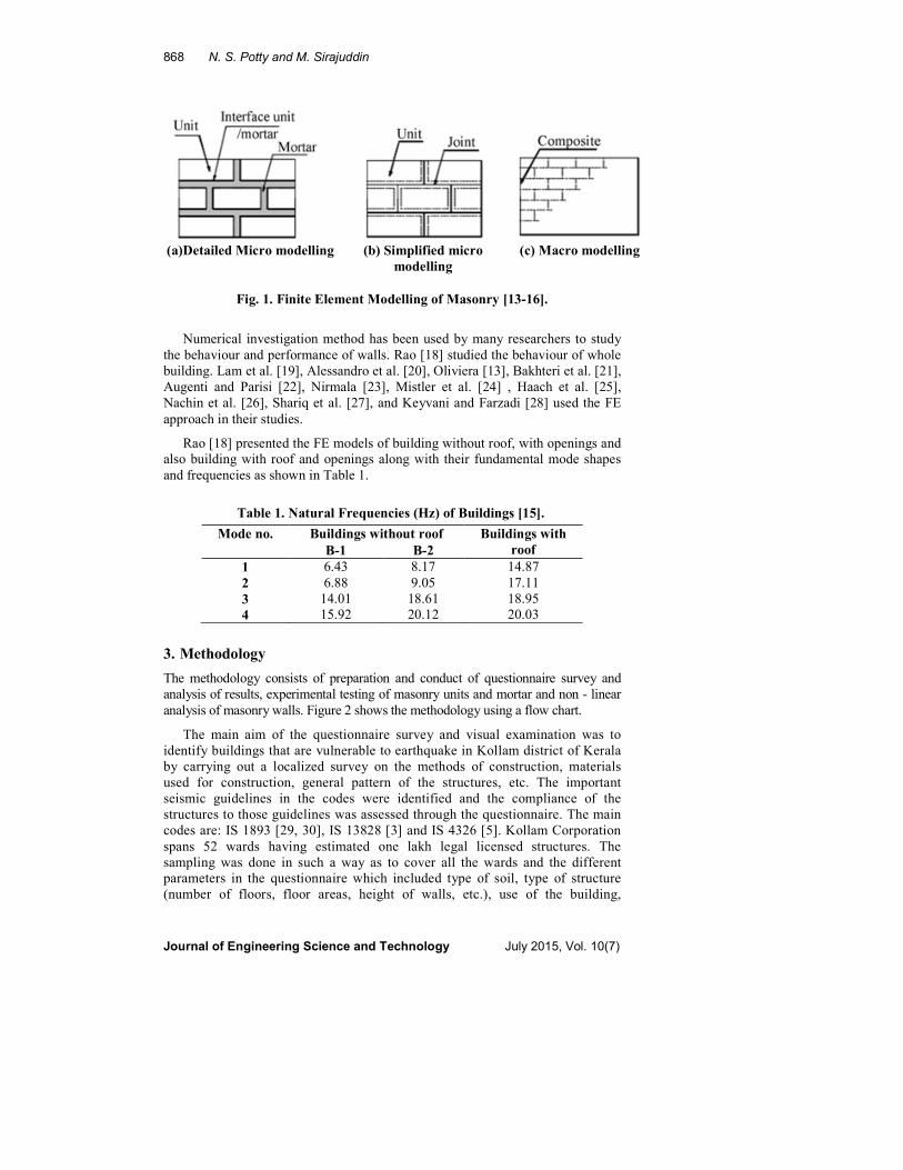
desired and the application field [14-16]. The present research uses detailed micro
modelling, in which units and mortar joints are represented by continuum elements
whereas the unit-brick interface is represented by discontinuous elements. Figure
1(a) shows the detailed micro modelling. The main advantage of detailed micro
modelling is that almost all the failure modes can be considered. But it is not
convenient for the modelling of large scale masonry structure, because the number
of elements that must be used can be huge, and consequently the cost of calculation
time increase tremendously. Memory requirements are also very high. In Simplified
Micro modelling, expanded units are represented by continuum elements whereas
the behaviour of the mortar joints and unit-mortar interface is lumped in
discontinuous elements. These interface elements represent the preferential crack
locations where tensile and shear cracking occur.
Figure 1(b) shows the simplified micro modelling. In Macro modelling, the
units, mortar and unit-mortar interface are smeared out in the continuum.
Figure 1(c) shows the Macro modelling. Macro modelling is more practice
oriented due to the reduced time and memory requirements as well as user
friendly mesh generation. This type of modelling is most valuable when a
compromise between accuracy and efficiency is needed [13-16]. More details
are reported in Potty and Sirajuddin [17].
Page 4
868 N. S. Potty and M. Sirajuddin
Journal of Engineering Science and Technology July 2015, Vol. 10(7)
(a)Detailed Micro modelling (b) Simplified micro
modelling
(c) Macro modelling
Fig. 1. Finite Element Modelling of Masonry [13-16].
Numerical investigation method has been used by many researchers to study
the behaviour and performance of walls. Rao [18] studied the behaviour of whole
building. Lam et al. [19], Alessandro et al. [20], Oliviera [13], Bakhteri et al. [21],
Augenti and Parisi [22], Nirmala [23], Mistler et al. [24] , Haach et al. [25],
Nachin et al. [26], Shariq et al. [27], and Keyvani and Farzadi [28] used the FE
approach in their studies.
Rao [18] presented the FE models of building without roof, with openings and
also building with roof and openings along with their fundamental mode shapes
and frequencies as shown in Table 1.
Table 1. Natural Frequencies (Hz) of Buildings [15].
Mode no. Buildings without roof Buildings with
roof B-1 B-2
1 6.43 8.17 14.87
2 6.88 9.05 17.11
3 14.01 18.61 18.95
4 15.92 20.12 20.03
3. Methodology
The methodology consists of preparation and conduct of questionnaire survey and
analysis of results, experimental testing of masonry units and mortar and non - linear
analysis of masonry walls. Figure 2 shows the methodology using a flow chart.
The main aim of the questionnaire survey and visual examination was to
identify buildings that are vulnerable to earthquake in Kollam district of Kerala
by carrying out a localized survey on the methods of construction, materials
used for construction, general pattern of the structures, etc. The important
seismic guidelines in the codes were identified and the compliance of the
structures to those guidelines was assessed through the questionnaire. The main
codes are: IS 1893 [29, 30], IS 13828 [3] and IS 4326 [5]. Kollam Corporation
spans 52 wards having estimated one lakh legal licensed structures. The
sampling was done in such a way as to cover all the wards and the different
parameters in the questionnaire which included type of soil, type of structure
(number of floors, floor areas, height of walls, etc.), use of the building,
Page 5
Study of Empirical Seismic Codal Guidelines for Masonry Buildings in . . . . 869
Journal of Engineering Science and Technology July 2015, Vol. 10(7)
strategic importance of buildings, general strength of masonry (considering
types of masonry, mortar composition, plastering, length of longest wall, use of
water proof plaster, etc.), size and positions of openings in bearing walls (most
important criteria in IS 4326 [5] and IS 13828 [3]). Similarly the pier width
between consecutive openings, distance of the first opening from inside corner
of outside wall, etc., were included.
Various materials are nowadays used as building blocks. So laterite, wire cut
and country burnt bricks, Hollow cement block, solid cement block, Random
Rubble masonry, Interlocking bricks, wooden planks, etc., were included. Type of
roof, provision of all round lintel and lintel thickness, symmetry and age of
structure, type of sub structure, average number of occupants, use of the structure,
soft storey, presence and placement of high weight RCC overhead tanks
(placement of water tank at the geometric centroid of plan area and importance of
tying it to the structure were also considered). Further the type of water tank
(Fibre reinforced, RCC or masonry) was also noted. The presence of high rise
towers adjacent to the assessed structure, attachment of staircase to the structure,
loss of symmetry due to expansion of the building and quality of work and long
term durability was also considered. The questionnaire was prepared based on the
detailed study of IS 1893 [29], IS 4326 [5], IS 13827 [6], IS 13828 [7], IS 13920
[31] and IS 1905 [4]. The questionnaire had 30 questions.
The experimental work consists of two parts. Evaluation of properties of wall
materials included the compressive strength, water absorption and efflorescence of
laterite blocks, country burnt bricks, wire-cut bricks, concrete blocks, hollow blocks
and interlocking blocks. Evaluation of the basic material properties of brick units
and mortar units such as Poisson’s ratio, modulus of elasticity and compressive
strength are necessary for numerical modelling and seismic analysis of masonry
wall. Only bricks were considered in the numerical modelling since they constitute
the major share of the building stock (44.9% of the total housing stock).
Experimental study was conducted on three varieties of brick units which included
two types of wire cut bricks and one type of country burnt brick, collected from
different kilns of Kollam District. The properties of brick and mortar were evaluated
(and not the wall) since for the numerical modelling the micro – modelling
approach of brick and mortar was used. In the assessment of safety of the walls
under applied loads, a permissible compressive stress of 0.35 N/m2 was assumed
based on Varghese [32] and IS 13828 [7].
Test on compressive strength and water absorption test were carried out as per
IS 3495 (part 1 to 4) [33]. The strength of masonry depends on strength of brick and
mix proportion of mortar. In India, lower mix proportion of cement and sand is
often used. But IS 4326 [5] recommends minimum 1:6 mix proportion of cement
and sand. In this experimental study, three different mix proportions of cement and
sand were considered for the mortar preparation.
The finite element method and ANSYS [34] was used for the numerical
investigation of masonry walls. The numerical investigation of wall consisted of
two stages (1) Modal analysis – which was used to study the mode shapes and
natural frequency of vibration of masonry wall models. The modal analyses of
masonry walls without opening were carried out for various mortar mixes such as
1:4 mix, 1:6 mix and 1:8 mix. Model 1 was used for this part of study (2) The
nonlinear dynamic analysis of wall model with and without incorporating some
Page 6
870 N. S. Potty and M. Sirajuddin
Journal of Engineering Science and Technology July 2015, Vol. 10(7)
prescriptive guidelines provided in the codes for checking their efficacy was
carried out in three sub - phases.
Fig. 2. Flow Chart of Methodology for
Questionnaire Survey and Experimental Work.
(a) Sub- stage 1: Model 1 was subjected to only in-plane ground motion for
mortar 1:4, 1:6 and 1:8. The purpose is to assess the impact of mortar type on
the stresses.
Page 7
Study of Empirical Seismic Codal Guidelines for Masonry Buildings in . . . . 871
Journal of Engineering Science and Technology July 2015, Vol. 10(7)
(b) Sub – stage 2: Models 2, 3, 4 and 5 subject to in-plane and out of plane
ground motions for mortars 1:4 and 1:6 only. The aim was to identify the effect of
openings and pier size.
(c) Sub – stage 3: Model 6, 7 and 8 subject to in-plane and out-of-plane
ground motions for mortar mix 1:6 only. The aim was to identify the effect of
providing frames/ lintels around and over openings and to evaluate the stress
change due to the frame/ lintel.
The wall used for study having size 3.6 m length×2.7 m height was modelled
using Solid 65 element.
The details of the 8 models are: (1)Wall without opening, (2) Wall with
window of size 1.5 m×1.0 m, (3) Wall with door (0.9 m×2.0 m) and window of
size (1.2 m×1.0 m) located at the centre of wall keeping pier distance as 0.6 m, (4)
Wall with door (0.9 m×2.0 m) and window of size (1.2 m×1.0 m) located at the
centre of wall keeping pier distance as 0.34 m, (5) Wall with door (1.0 m×2.0 m)
and window of size (1.35 m×1.2 m) located at the centre of wall keeping pier
distance as 0.60 m. Edge distance was 0.325 m, (6) Wall with door (0.9 m×2.0 m)
and window of size (1.0 m×1.2 m) located at the centre of wall keeping pier
distance as 0.34 m. A concrete frame of thickness 0.12 m provided around the
opening (7) Wall with window of size (1.5 m×1.0 m) located at the centre of wall.
A concrete frame of thickness 0.12 m provided around the opening (8) Wall with
door of size (1.0 m×2.0 m) and window opening of size 1.35 m×1.2 m located at
the centre of wall by keeping pier distance as 0.6 m. A concrete frame of
thickness 0.12 m is provided around the opening. The models are compared in
Table 2. Models 5 and 8 did not comply with the requirement that opening width
should be less than or equal to L/3.
The mortar mix proportions of 1:4 and 1:6 were used since 1:8 mix proportion is
not recommended for earthquake prone areas. The base of each model is assumed as
“fixed”. Each model was subjected to uniform distributed vertical load of intensity of
6kN/m. In this study, acceleration time data of Bhuj earthquake was normalised by
multiplying with a factor 0.7326 to make it equivalent to that of the ground motion of
Kerala region for a period of 20 seconds. The multiplying factor is obtained by
dividing the maximum expected PGA value of Kerala 0.278g with the PGA value of
Bhuj EQ 0.36g (0.278g\0.36g=0.7326). The normalised acceleration time data of
Bhuj earthquake was adopted for the study. The ground motion equivalent to that of
the Bhuj earthquake was applied on the models, both in - plane and out - of - plane to
the masonry wall and the stresses on the walls were evaluated.
4. Results and Discussion
The first four natural frequencies of vibration of the modelled brick wall for three
different mortar proportions fall in the range of 1-13 Hz. The results of Rao [18]
are having higher natural frequencies namely 6-20 Hz for the whole structure
since the whole structure is more rigid. The results of Lam et al. [19] fall in the
range 5-10 Hz where walls were modelled. Amrheim [35] noted that URM
buildings are stiff structures with natural frequencies in the range 2 - 10 Hz. Hence
the current micro finite element modelling of the masonry wall is also verified.
Page 8
872 N. S. Potty and M. Sirajuddin
Journal of Engineering Science and Technology July 2015, Vol. 10(7)
Table 2. Summary of Parameters of
Models Tested for its Influence on Seismic Resistance.
+ Concrete frame of thickness 0.12 m provided around the openings
Φ Concrete beam around the openings
β concrete frame of 0.12 m thickness
4.1. Questionnaire survey results
A total of 6800 data was used for the analysis. The statistics of the buildings
analysed consisted of residential buildings (64.2%), commercial buildings
(19.2%), industrial buildings (1%), government buildings (3.5%), hospitals and
public buildings, and educational buildings (5.1%). The detailed analysis of the
buildings on their compliance with the seismic resistant provisions was presented
in Potty and Sirajuddin [36, 37].
Many buildings in Kollam city seem to have sufficient resistance against
moderate earthquakes as per Indian standard specifications and general
criteria. Immediate and important attention is required for the residential
structures. The growth rate of residential structures is very high and just a few
have got seismic resistance of its own. Government should impose new rules
regarding seismic resistance regulations and should educate the public about
the possible damages due to earthquakes. The tendency of providing large
openings and asymmetric designs are to be curbed. Economic retrofits in the
form of wire meshed concrete on the corners of masonry walls in tiled roof
structures and division of longer walls to shorter ones can be done for
structures greater than 30 years of age. In commercial structures strict rules
must be imposed to avoid huge capacity overhead water tanks. Also the
provision of open cellar area for parking must be avoided. Tie beams at
regular intervals should be provided for structures having floor height higher
than 4 m. Alternate technology must be developed to remove the mobile
service towers from highly occupied areas due to danger of collapse. Schools
should be of single storey as far as possible. The water tanks must be kept
away from the buildings in the school campus. The structural support between
roof and walls of old tiled buildings should be improved by using cleat and
angles connection. Long and big construction in a single stretch must be
avoided. Smaller structure must be placed well apart [36-38].
Mod
el
L (
m)
H (
m)
Win
dow
size
(m
)
Do
or
size
(m)
%
Op
enin
g
wid
th n
ot
gre
ate
r
than
L/3
CM
Pie
r si
ze
(m)
1 3.6 2.7 - - - OK 1:4, 1:6,
1:8
-
2 3.6 2.7 1.5×1.0 - 15.42 OK 1:4, 1:6, - 3 3.6 2.7 1.2×1.0 0.9×2.0 30.86 OK 1:4, 1:6 0.6
4 3.6 2.7 1.2×1.0 0.9×2.0 30.86 OK 1:4, 1:6 0.34
5 3.6 2.7 1.35×1.2 1.0×2.0 37.24 Not OK 1:4, 1:6 0.6
Edge distance =0.325
6+ 3.6 2.7 1.0×1.2 0.9×2.0 30.86 OK 1:4, 1:6 0.34 7Φ 3.6 2.7 1.5×1.0 - 15.43 OK 1:6 -
8β 3.6 2.7 1.35×1.2 1.0×2.0 37.24 Not OK 0.6
Page 9
Study of Empirical Seismic Codal Guidelines for Masonry Buildings in . . . . 873
Journal of Engineering Science and Technology July 2015, Vol. 10(7)
4.2. Experimental tests on masonry units and mortar
The experimental testing was structured to identify the properties of the masonry
units and mortars prepared locally. The properties of the bricks and blocks were
compared with the limits proposed in the codes namely IS 2185 [39] and IS 1077
[40]. The experimental study on materials for wall construction revealed that,
most of them failed to meet the standard specified by IS. It is mainly due to poor
quality control and use of inferior quality raw materials. It was found that wire cut
bricks were the most ideal material available for construction of walls. It meets
strength requirements and it is economical.
Basic material properties such as Compressive Strength, Modulus of Elasticity
and Poisson’s ratio of the three varieties of brick and the Compressive Strength,
Modulus of Elasticity and Poisson’s ratio of the three different mix proportions of
mortar were experimentally determined. The choice of wire cut and fired brick
and three mortars (1:4, 1:6 and 1:8) were identified for numerical analysis.
4.3. Evaluation of efficiency of the empirical seismic guidelines for
masonry buildings
The results of modal analysis of masonry wall of three different mortar mixes and
without opening were compared. The masonry walls with richer mortar mixes
have higher frequencies because they are stiffer, as expected. The frequencies also
agree well with frequencies of models of masonry walls and whole houses, which
verifies the micro finite element models.
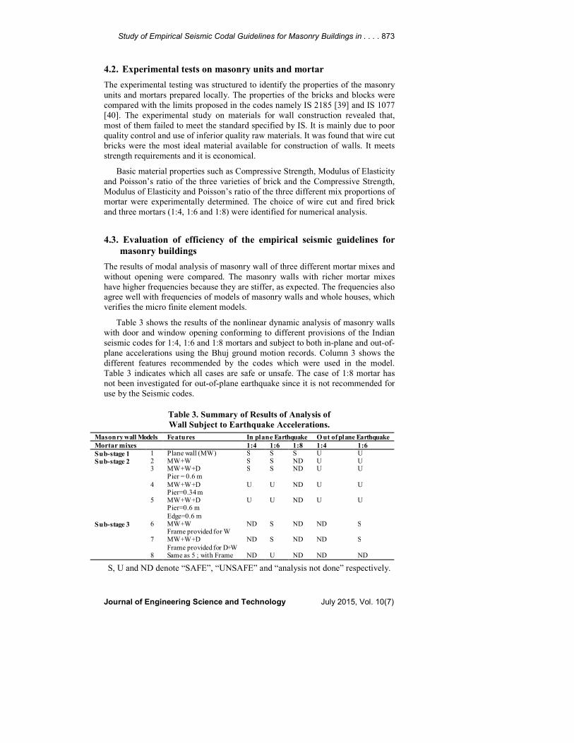
Table 3 shows the results of the nonlinear dynamic analysis of masonry walls
with door and window opening conforming to different provisions of the Indian
seismic codes for 1:4, 1:6 and 1:8 mortars and subject to both in-plane and out-of-
plane accelerations using the Bhuj ground motion records. Column 3 shows the
different features recommended by the codes which were used in the model.
Table 3 indicates which all cases are safe or unsafe. The case of 1:8 mortar has
not been investigated for out-of-plane earthquake since it is not recommended for
use by the Seismic codes.
Table 3. Summary of Results of Analysis of
Wall Subject to Earthquake Accelerations.
S, U and ND denote “SAFE”, “UNSAFE” and “analysis not done” respectively.
Masonry wall Models Features In plane Earthquake O ut of plane Earthquake
Mortar mixes 1:4 1:6 1:8 1:4 1:6
Sub-stage 1 1 Plane wall (MW) S S S U U
Sub-stage 2 2 MW+W S S ND U U 3 MW+W+D
Pier = 0.6 m S S ND U U
4 MW+W+D Pier=0.34 m
U U ND U U
5 MW+W+D Pier=0.6 m
Edge=0.6 m
U U ND U U
Sub-stage 3 6 MW+W Frame provided for W
ND S ND ND S
7 MW+W+D
Frame provided for D+W
ND S ND ND S
8 Same as 5 ; with Frame ND U ND ND ND
Page 10
874 N. S. Potty and M. Sirajuddin
Journal of Engineering Science and Technology July 2015, Vol. 10(7)
5. Conclusions
From the questionnaire survey analysis, the following general conclusions can be made.
• In general, many buildings in Kollam city seem to have sufficient resistance
against moderate earthquakes as per Indian standard specifications and
general criteria.
• The rapid growth of residential structures and lack of seismic resistance
requires attention of authorities. Government should impose new rules
regarding seismic resistance regulations and should educate the public about
the possible damages due to earthquakes.
• The tendency of providing large openings and asymmetric designs are to be curbed.
• Economic retrofits in the form of wire meshed concrete on the corners of
masonry walls in tiled roof structures and division of longer walls to shorter
ones can be done for structures greater than 30 years of age.
• In commercial structures strict rules must be imposed to avoid huge capacity
overhead water tanks. Also the provision of open cellar area for parking must
be avoided. Tie beams at regular intervals should be provided for structures
having floor height higher than 4 m.
• Alternate technology must be developed to remove the mobile service towers
from highly occupied areas due to danger of collapse.
• Schools should be of single storey as far as possible. The water tanks must be
kept away from the buildings in the school campus.
• The structural support between roof and walls of old tiled buildings should be
improved by using cleat and angles connection.
• Long and big construction in a single stretch must be avoided. Smaller
structure must be placed well apart.
From the nonlinear analysis on the eight wall models structures to examine the
seismic provisions of the code, the conclusions are
• In the masonry wall with rich mortar mix proportion, the magnitude of
maximum stresses developed was found to be small under the nonlinear
dynamic analysis.
• Wall was more vulnerable to earthquake in out-of-plane direction than to
earthquake in in-plane direction. When the wave hit in the out-of-plane
direction of wall, the stiffness offered by the wall was less, or the height to
thickness ratio was much greater.
• The wall was safe in in-plane dynamic loading when the pier distance was
kept at 0.6 m for mortar mix proportion of 1:4 and 1:6. But it was not safe
against out-of-plane loading.
• When the pier distance was reduced to 0.34 m, the equivalent stress
developed on the wall was more than the stress developed in the case of pier
distance of 0.6 m, for mortar mix proportion 1:4 and 1:6. In this case, the
maximum stress developed was more than the permissible crushing or
compressive strength (0.35 N/mm2) of masonry, for both mortar mix
proportions. So masonry wall was not safe in both in-plane and out-of-plane
dynamic loading for a pier distance of 0.34 m. So in this case, the IS code
recommendation is not being satisfied, even in the in-plane loading.
Page 11
Study of Empirical Seismic Codal Guidelines for Masonry Buildings in . . . . 875
Journal of Engineering Science and Technology July 2015, Vol. 10(7)
• When sizes of openings were increased and the positions of openings were
kept near the edge of the wall, the maximum equivalent stress was found to
be developed at the bottom corner of the opening. Here the opening from the
edge of the wall is at a distance of 0.325 m, which is more than the thickness
of the wall. Even in this case, the wall is not safe in in-plane and out-of-plane
dynamic loading and it does not satisfy the code recommendation for
minimum edge distance.
• It was found that providing a concrete frame around the openings of the wall
with a pier distance of 0.34 m will make the existing unreinforced brick
masonry structure safe against collapse. In this case, concrete frame takes the
stresses acting on the wall. The maximum equivalent stress (1.69 N/mm2 in
in-plane and 1.7 N/mm2 in out-of-plane loading) developed in the model was
less than the permissible stress of concrete (20 N/mm2).
• It is to be noted that the concrete frame consisted of M20 concrete and
reinforcement bars as per seismic guidelines (10 cm thick beam and 8 mm
diameter reinforcement bar).
• When the size of opening was increased and the position of opening was kept
near the edge of the wall, the structure was not safe even in the in-plane
loading. So the opening near the edge of the wall should be avoided.
Acknowledgements
The author’s acknowledge the undergraduate and postgraduate students involved
in this work. The facilities provided by TKM College of Engineering for
laboratory testing and computer analysis is acknowledged.
References
1. Bhowmik, A.; and Mohanty, S.P. (2008). Analysis and design of earthquake
resistant masonry building. B. Tech Thesis, Department of Civil
Engineering, NIT Rourkela.
2. Constructor.org. (2012). Performance of various types of buildings during
earthquakes. Retrieved August 11, 2012, from constructor.org.
3. IS 13828. (1993). Indian standard guidelines for improving earthquake
resistance of low strength masonry buildings. BIS, New Delhi.
4. IS 1905. (1987). Indian standard code of practice for structural use of
unreinforced masonry. BIS, New Delhi
5. IS 4326. (1993). Indian standard code of practice for earthquake resistant
design and construction of buildings (2nd Revision). BIS, New Delhi.
6. IS 13827. (1993). Indian standard guidelines for improving earthquake
resistance of earthen buildings. BIS, New Delhi
7. Sajudeen, N.; and Latheswary, S. (2012). Seismic hazard assessment of
Kerala. International Conference on Challenges in Environmental Science
and Engineering, 9-13 September, Melbourne, Australia.
Page 12
876 N. S. Potty and M. Sirajuddin
Journal of Engineering Science and Technology July 2015, Vol. 10(7)
8. Staff reporter. (2004). Kerala vulnerable to earthquakes. The Hindu,
National Newspaper. Retrieved January 9, 2015, from http://www.thehindu.
com/ 2004/02/08/stories/2004020806000500.htm.
9. Kerala State Disaster Management Authority, GOK Government of Kerala.
(2012). Kerala state disaster management plan profile. Retrieved January 9,
2015, from http://www.kerenvis.nic.in/WriteReadData/UserFiles/file/49412317.
10. Jaya, V.; and Remmya, U.R. (2010). Seismic microzonation of
Thiruvananthapuram. Indian Geotechnical Conference, 667-670.
11. Sitharam, T.G.; and Anbazhagan, P. (2008). Seismic micro- zonation:
principles, practices and experiments. The Electronic Journal of
Geotechnical Engineering, Bouqet 2008, 1-61.
12. Potty, N.S.; Sirajuddin, M.; and Arjun, V.K. (2005). Wall construction using
substitute materials. International Conference on Construction and Real
Estate Management, 12-13 December, Penang, Malaysia.
13. Oliviera, D.V.D.C. (2003). Experimental and numerical analysis of blocky
masonry structures under cyclic loading. PhD thesis, School of Engineering,
University of Minho, January.
14. Lorenco, P.B. (1994). Analysis of masonry structures with interface
elements. TU Delft, The Netherlands.
15. Lorenco, P.B. (1998). Experimental and numerical issues in the modeling of
the mechanical behaviour of masonry in structural analysis of historical
constructions II. P.Roca, J.I., Gonzalez, E., E. Onate and P.B. Lourenco
(Eds.), Barcelona.
16. Lorenco, P.B. (1996). A user / programmer guide for the micro modeling of
masonry structures, Report 03.21.1.31.35, TU Delft, The Netherlands
17. Potty, N.S.; and Sirajuddin, M. (2011). Nonlinear seismic analysis of
masonry structures. Journal of Design and Built Environment, 9, 1-16.
18. Rao, K.S.N. (2012). Structural masonry: properties and behaviour.
Department of Civil Engineering, Indian Institute of Science, Bangalore, India.
19. Lam, N.T.K.; Wilson, J.L.; and Hutchinson, G.L. (1995). The seismic
resistance of unreinforced masonry cantilever walls in low seismicity areas.
Bulletin of NZ National Society for Earthquake Engineering, 28, 3, 179-195.
20. Alessandro, G.; Sergio L.; Andrea P.; and Sonia, R. (2004). Non-linear
seismic analysis of masonry structures. 13th
World Conference on Earthquake
Engineering, 8, 11-26.
21. Bakhteri, J.; Mahir, A.; Makhtar.; and Shamala, S. (2004). Finite element
modelling of structural clay brick masonry subjected to axial compression.
Journal Teknologi, 41(B), 57-68.
22. Augenti, N.; and Parisi, F. (2004). Nonlinear static analysis of masonry
structures. Journal of Earthquake Engineering, 8, 497-511.
23. Nirmala (2005). Laterite interlocking block in filled multi storied frames. M-
Tech thesis, TKM College of Engineering, Kerala University, Kollam, India.
24. Mistler, M.; Butenweg, C.; and Meskouris, K. (2006). Modelling of historic
masonry buildings under seismic excitation. Journal of Seismology, 10(4),
497-510.
Page 13
Study of Empirical Seismic Codal Guidelines for Masonry Buildings in . . . . 877
Journal of Engineering Science and Technology July 2015, Vol. 10(7)
25. Haach, V.G.; Vasconcelos, G.; Lourenço, P.B.; and Mohamad, G. (2007).
Composition study of a mortar appropriate for masonry cavities and joints. 10th
North American Masonry Conference, June 3-6, St Louis, Missouri, USA.
26. Nachin, J.; Qing, M.; and Yixiong, Z. (2007). Research on time – history
input methodology of seismic analysis. Transactions of Structural
Mechanical in Reactor Technology, 19, Toronto.
27. Shariq, M.; Abbas, H.; Irtaza, H.; and Qamaruddin, M. (2008). Influence of
openings on seismic performance of masonry building walls. Building and
Environment, 43(7), 1232-1240.
28. Keyvani, J.; and Farzadi, M. (2011). Impact of brick infill walls on the
seismic behaviour of reinforced concrete frames using finite element method.
Asian Journal of Civil Engineering (Building and Housing), 12(6), 789-802.
29. IS 1893 Part 1. (2002). Criteria for earthquake resistant design of structure:
general provisions and buildings. BIS, New Delhi.
30. IS 1893. (1984). Criteria for earthquake resistant design of structure. BIS,
New Delhi.
31. IS 13920. (1993). Indian standard code of practice for ductile detailing of
reinforced concrete structures subjected to seismic forces. BIS, New Delhi
32. Varghese, P.C. (2005). Building Materials. Eastern Economic Edition,
Prentice Hall India, New Delhi. ISBN-81-203-2848-5.
33. IS 3495 (Part 1 to 4). (1992). Indian standard methods for test for burnt clay
building bricks. BIS, New Delhi, India.
34. ANSYS Inc. (2003). ANSYS User’s manual for Revision 8.0.
35. Amrhein, J.E. (1998). Reinforced masonry handbook: clay and concrete
masonry. MIA, Los Angeles, California, USA.
36. Potty, N.S.; and Sirajuddin, M. (2011). Seismic risk assessment of buildings
in Kollam India. International Building and Infrastructure Technology
Conference, Universiti Sains Malaysia, June 7-8.
37. Potty, N.S.; and Sirajuddin, M. (2011). Assessment of building for seismic
resistance. Malaysian Journal of Civil Engineering, 23(1), 86-104.
38. Narayanan, S.; and Sirajuddin, M. (2004). Strategies for improving
earthquake resistance of masonry structures in Kerala. National Conference
on Recent Advances in Civil Engineering, CUSAT, Kerala.
39. IS 2185 Part 1. (1979) (Reaffirmed 1987). Indian standard specification for
concrete masonry units: hollow and solid concrete blocks. 2nd
Revision, BIS,
New Delhi.
40. IS 1077. (1992). Specification for common burnt clay building bricks (third
revision). BIS, New Delhi.