Study on Evaluation of Fine Fraction Content of Soil Using Soil-Metal Friction Sound for Liquefaction Assessment by Swedish Ram Sounding Suguru YAMADA and Akihiko OSHIMA (Received October 2, 2015) Synopsis This article presents a possible idea for evaluating fine fraction content of subsurface soil through an operation of Swedish Ram Sounding (SRS) by employing acoustic properties of friction sound generating by friction occurs between surface of metallic penetration cone and surrounding soil. A series of soil-metal friction test was performed on silica sand with various fines content using a modified direct box shear apparatus to simulate a friction phenomenon between SRS cone and surrounding soil. As a result of experiments, it was found that the sound pressure level (SPL) of friction sound was depended on relative density as well as fines content of sandy specimen. Based on obtained testing results, an idea for evaluating fines content of ground by SRS was tentatively proposed. KEYWOEDS: Liquefaction, Dynamic corn penetration, Friction, Sound pressure level 1. Introduction In response to liquefaction-caused severe damages in residential ground during the 2011 off the Pacific coast of Tohoku Earthquake, demands for applying measures against liquefaction to residential properties has been risen up in Japan. It is, however, not simple to assess the safeness against liquefaction in an individual residential property with applying conventional FL method, in which grain-size properties of particular stratum are required, because of the difficulty to take soil samples from ground by conventional field investigation techniques which have been employed in the small house constructions. Therefore, it is necessary to develop technologies, with reasonable cost, evaluating grain-size properties of soil for the residential ground, in order to achieve liquefaction assessment to residential properties. In the present study, it was attempted evaluating fines content by employing the friction sound generating underground during the work of Swedish Ram Sounding (SRS). The SRS, a dynamic cone penetration test, has been recently becoming a major field investigation technique for residential property in Japan. As a part of process in SRS work, the torque is measured by rotating a penetration rod at every 0.2m in the penetration length to correct the effect of skin friction resistance on number of blow (N dm ). A stainless steel cone with a diameter of 45mm was made 2 turns at an angular velocity approximately 47deg/sec in the ground during torque measurement. Meanwhile, the generated friction sound by the friction of cone with soil was recorded. If this frictional behaviour is assumed as the shear occurs between stainless steel and soil, it can be thought that the recorded sound was generated when large shear deformation was developed between stainless steel and soil. Therefore in this study, a series of direct box shear test was performed on silica sand with various fines content using a direct box shear apparatus, simulating the friction behaviour between stainless steel and soil in the torque measurement. The friction sound was recorded during shear, then relations between sound pressure level (SPL) of friction sound and fines content was well as relative density of specimens were investigated. 2. Apparatus and Experimental Procedure Direct box shear test Direct box shear tests were performed using a standard type direct box shear apparatus (JGS 0560-2000) 1) . An upper shear box of the apparatus was switched to a plate of stainless steel (SUS304) in which a piezoelectric Lecturer, Department of Urban Engineering Professor, Department of Urban Engineering -29-
Transcript
Study on Evaluation of Fine Fraction Content of Soil Using Soil-Metal Friction Sound for Liquefaction Assessment by Swedish Ram Sounding
Suguru YAMADA and Akihiko OSHIMA
(Received October 2, 2015)
Synopsis
This article presents a possible idea for evaluating fine fraction content of subsurface soil through an operation of Swedish Ram Sounding (SRS) by employing acoustic properties of friction sound generating by friction occurs between surface of metallic penetration cone and surrounding soil. A series of soil-metal friction test was performed on silica sand with various fines content using a modified direct box shear apparatus to simulate a friction phenomenon between SRS cone and surrounding soil. As a result of experiments, it was found that the sound pressure level (SPL) of friction sound was depended on relative density as well as fines content of sandy specimen. Based on obtained testing results, an idea for evaluating fines content of ground by SRS was tentatively proposed. KEYWOEDS: Liquefaction, Dynamic corn penetration, Friction, Sound pressure level
1. Introduction In response to liquefaction-caused severe damages in residential ground during the 2011 off the Pacific coast
of Tohoku Earthquake, demands for applying measures against liquefaction to residential properties has been risen up in Japan. It is, however, not simple to assess the safeness against liquefaction in an individual residential property with applying conventional FL method, in which grain-size properties of particular stratum are required, because of the difficulty to take soil samples from ground by conventional field investigation techniques which have been employed in the small house constructions. Therefore, it is necessary to develop technologies, with reasonable cost, evaluating grain-size properties of soil for the residential ground, in order to achieve liquefaction assessment to residential properties.
In the present study, it was attempted evaluating fines content by employing the friction sound generating underground during the work of Swedish Ram Sounding (SRS). The SRS, a dynamic cone penetration test, has been recently becoming a major field investigation technique for residential property in Japan. As a part of process in SRS work, the torque is measured by rotating a penetration rod at every 0.2m in the penetration length to correct the effect of skin friction resistance on number of blow (Ndm). A stainless steel cone with a diameter of 45mm was made 2 turns at an angular velocity approximately 47deg/sec in the ground during torque measurement. Meanwhile, the generated friction sound by the friction of cone with soil was recorded. If this frictional behaviour is assumed as the shear occurs between stainless steel and soil, it can be thought that the recorded sound was generated when large shear deformation was developed between stainless steel and soil. Therefore in this study, a series of direct box shear test was performed on silica sand with various fines content using a direct box shear apparatus, simulating the friction behaviour between stainless steel and soil in the torque measurement. The friction sound was recorded during shear, then relations between sound pressure level (SPL) of friction sound and fines content was well as relative density of specimens were investigated.
2. Apparatus and Experimental Procedure
Direct box shear test
Direct box shear tests were performed using a standard type direct box shear apparatus (JGS 0560-2000)1). An upper shear box of the apparatus was switched to a plate of stainless steel (SUS304) in which a piezoelectric
Lecturer, Department of Urban Engineering Professor, Department of Urban Engineering
-29-
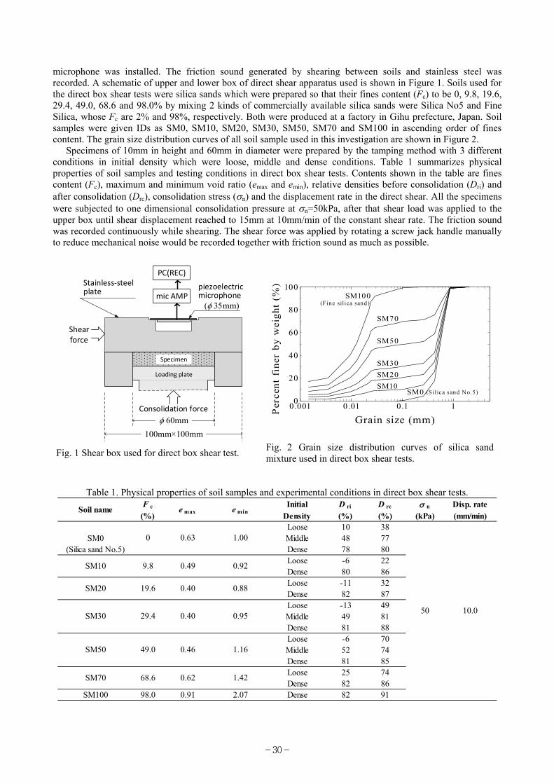
microphone was installed. The friction sound generated by shearing between soils and stainless steel was recorded. A schematic of upper and lower box of direct shear apparatus used is shown in Figure 1. Soils used for the direct box shear tests were silica sands which were prepared so that their fines content (Fc) to be 0, 9.8, 19.6, 29.4, 49.0, 68.6 and 98.0% by mixing 2 kinds of commercially available silica sands were Silica No5 and Fine Silica, whose Fc are 2% and 98%, respectively. Both were produced at a factory in Gihu prefecture, Japan. Soil samples were given IDs as SM0, SM10, SM20, SM30, SM50, SM70 and SM100 in ascending order of fines content. The grain size distribution curves of all soil sample used in this investigation are shown in Figure 2.
Specimens of 10mm in height and 60mm in diameter were prepared by the tamping method with 3 different conditions in initial density which were loose, middle and dense conditions. Table 1 summarizes physical properties of soil samples and testing conditions in direct box shear tests. Contents shown in the table are fines content (Fc), maximum and minimum void ratio (emax and emin), relative densities before consolidation (Dri) and after consolidation (Drc), consolidation stress (n) and the displacement rate in the direct shear. All the specimens were subjected to one dimensional consolidation pressure at n=50kPa, after that shear load was applied to the upper box until shear displacement reached to 15mm at 10mm/min of the constant shear rate. The friction sound was recorded continuously while shearing. The shear force was applied by rotating a screw jack handle manually to reduce mechanical noise would be recorded together with friction sound as much as possible.
Table 1. Physical properties of soil samples and experimental conditions in direct box shear tests. F c Initial D ri D rc n Disp. rate(%) Density (%) (%) (kPa) (mm/min)
Fig. 1 Shear box used for direct box shear test. Fig. 2 Grain size distribution curves of silica sand mixture used in direct box shear tests.
-30-
Swedish Ram Sounding (SRS) Swedish Ram Sounding (SRS) which is corresponding to a DPSH-A (Super Heavy-A) in the dynamic probing
category according to ISO 22476-2(2005)2), measures two parameters; the one is the number of blow (Ndm) per 0.2m in penetration length with dropping a hammer having the mass of 63.5kg from the height of 0.5m, the other is the toque (Mv) required to rotate the rod at every 0.2m of penetration length in N-m. The SRS Nd-value can be given by following equation, in which Mv is employed to correct the skin friction resistance from Ndm (Dahlgerg and Bergdahl, 19743) and Oshima, 20134)). The SRS Nd-value can be considered nearly equal to the SPT N-value (NSPT) because the equal potential energy of free-falling hammer per unit penetration length has been adopted in both tests.
vdmSPT 04.0 MNN (1)
Figure 3 is a schematic of a condenser microphone embedded penetration cone used for recording friction sound by SRS. Note, the reason for employing the condenser microphone which is different kind from that used in the direct box shear test was to prevent the microphone from breaking or coming off during SRS work. A condenser microphone has higher structural strength than a piezoelectric microphone. The cone was screwed to the penetration rod, so that both could rotate together while the torque measurement. The torque was measured at every 0.2m of penetration depth by rotating penetration rod. The friction sound recording was continued while each 1m dynamic penetration would be completed.
PC(REC)
mic AMP
Hollow rod
Cone(Stainless-steel)
Condenser microphone
mic cap
Spring
(mm)
90°
Anvil(Stainless-steel)
mm
105m
m
Fig. 3 Schematic of penetration cone used for SRS.
Measurement and Analysis of Friction Sound The sound sensed by a microphone was amplified by a mic-amplifier then recorded at a sampling frequency of
44.1 kHz using PC software in both of direct box shear test and SRS. Employing a recorded sound by SRS performed at Urayasu city (Yamada and Oshima, 2015)5) as an example, the procedure of analyzing the friction sound is described below.
Figure 4 shows a waveform of sound which was recorded continuously during 1 m dynamic penetration, the corresponding penetration depth was from 10.4m to 11.4m. The process of SRS work and the position of microphone, which is equal to depth of the cone, are indicated in the figure. Where, “blow” and “tor” indicate the rammer blow process and the torque measurement process, respectively. It is observed that amplitude of sound recorded in all blow process was over the range of recordable volume, and amplitude in every torque measurements process demonstrates almost constant values. Considering facts that the cone was stationary in the
-31-
ground and almost no signal was observed at the time from the end of “blow” to the start of “tor”, the sound recorded in the torque measurement process can be determined as the sound generated by friction between outer periphery of stainless steel cone and surrounded soil.
blow blow blow blow blowtor tor tor tor torSRSprocess
mic position (depth)
10.6m10.8m 11.0m
11.2m11.4m
10.4m
Soun
d pr
essu
re (
Pa)
or
Sou
nd p
ress
ure
leve
l (dB
)
Fig. 4 Example of waveform recorded in SRS (Yamada and Oshima, 2015).
Figure 5 (a) shows a time history of sound pressure recorded at 10.6m in depth shown in Figure 4. The data shown in the figure is the signal of friction sound which was extracted from a raw data by applying the spectral subtraction (Boll, 1979)6). The data of 2 seconds before the start of torque measurement, cone was stationary at this time, were applied as a noise sample to the denoising. Figure 5(b) shows the corresponding sound pressure level (SPL) to Figure 5(a). The SPL can be calculated by following equation as an expression in Decibel.
20
2
10log10p
pSPL (in dB) (2)
Where, p is the sound pressure in Pa and p0 is a referential sound pressure equal to 20Pa which is known as minimum sound pressure human being can recognize.
Figure 5(c) shows a spectrogram calculated from the data shown in Figure 5(a) in the gray scale display in which the larger SPL is indicated by deeper black color. Where, the spectrogram is often-used expression in the acoustic phonetics which expresses a time series variation of the frequency spectrum indicating the intensity of frequency component by color gradations. It can be understood from Figures 5(b) and (c) that the friction sound recorded during the torque measurement is indicating stable SPL with approximately 65dB as well as showing the less variation in the frequency spectrum along time. In the present study, therefore, an average of SPL of entire data recorded in single torque measurement is defined as the mean SPL, representing an acoustic property of the friction sound.
3. Experimental Result
As an example of the field measurement by SRS, the results obtained at a site in Osaka city is shown in Figure 6. As for details of site profile etc., refer Mine et al. (2015)7). The figure illustrates relations between mean SPL and Fc at same depth. The data of Fc were obtained from soil samples of SPT performed at same date. Symbols are indicating an individual soil classifications. A general trend can be observed that the mean SPL decreases with an increasing in Fc, the trend seems to be independent from the difference of soil type. This result may suggest that there is a correlation between the loudness of the friction sound and the grain-size characteristics.
-32-
SRS, Urayasu Minato, 10.6m
(c)
(a)
(b)
Time (sec)
4050
(dB)
60
freq
uen
cy,
(Hz)
So
un
d P
ress
ure
,
p(P
a)S
PL
(d
B)
Torque measurement (approx. 15.3sec)
-2 0 2 4 6 8 10 12 14 16 1810
2
103
104
-0.10
-0.05
0.00
0.05
0.10
30
40
50
60
70
80
Fig. 5 Time histories: (a) sound pressure, (b) sound pressure level and (c) power spectrum.
0 10 20 30 40 50 60 70 80 90 1000
10
20
30
40
50
SRS
mea
n S
PL
(d
B)
Fines content, Fc (%)
Suminoe-ku, Osaka
: CH: CLS: CL-S: CLS-G
: MLS: ML-S
: SF: SFG: S-FG
Fig. 6 Relation between SPL and fines content, result of field measurement by SRS.
Figure 7(a) and (b) show relations between shear stress and shear displacement as well as SPL and shear displacement obtained from direct box shear test on SM10 with loose density. In Figure 7(b), the Black colored indicates SPL recorded with 44.1 kHz in sampling frequency and the Yellow colored indicates data of their 4096 period (approximately 0.09 sec) moving average. The shear stress indicates almost constant value with small fluctuation after peak shear stress appeared at the beginning of the shearing. It can be observed in Figure 7(b) that SPL indicates larger value at the shear displacement less than approximately 1mm, and after that it indicates constant value in average showing large fluctuations in conjunction with the change of shear stress. Since almost constant value in both shear stress and SPL were obtained from all test conducted in the present study, the mean SPL which is a parameter represents an acoustic property of the friction sound was defined as an averaged SPL value obtained from 10 second’s data between 35 and 45 sec, which is corresponding to the range of the shear displacement from 5.8 to 7.5mm.
-33-
0 5 10 1510
30
50
700
5
10
SP
L (
dB
)
Disp. rate: 10mm/min
Direct shear test,n=50kPa, Fc=10%, Dri=0%
(a) 35~45sec
extracted Yellow: moving averagedeviations
(b)
Sh
ear
stre
ss
(k
N/m
2)
Shear Displacement (mm)
Fig. 7 Example result of direct box shear test: (a) Shear stress vs. shear disp.; (b) SPL vs. shear disp.
Figure 8 shows a relationship between mean SPL and Fc obtained from all direct box shear test performed. It should be mentioned that there is large difference in the mean SPL between SRS and direct box shear test. This difference can be considered to be due to that there were differences in the type of microphone, the shape of apparatus and the shear rate among the tests. However, a general trend can be observed that the mean SPL decreases with increasing in Fc except for the results of SM0 (Fc=0%) specimens. This observed trend is agreed with that shown in Figure 6 which was obtained from the field measurement by SRS. A probable reason for the smaller mean SPLs were resulted on SM0 is that most of particles were hard to move during shear because SM0 has narrow grain size range i.e. there is a minor difference in grain size among adjoining particles. Same reason might be applicable to the result on SM100. Figure 9 illustrates relations of mean SPL and relative density after consolidation (Drc). Lines indicated in the figure can be given by Equation 2 will be described later. It is evidence that mean SPLs of sandy soil with constant Fc are depended on Drc and they decrease with an increases in Drc. It can be considered that soil particles in specimens with high density should be difficult to move because the degree of confinement acting to soil particles to be greater when density of specimen is higher.
0 10 20 30 40 50 60 70 80 90 1000
5
10
15
20
25
30
Fines content, Fc (%)
mea
n S
PL
(d
B)
35-45sec
: Loose
n=50kPaDirect shear test
: Middle: Dense
0 10 20 30 40 50 60 70 80 90 1000
5
10
15
20
25
30
35
Fc=0%
10%
20%
30%
50% 70%
Direct shear test
Mea
n S
PL
(d
B)
Relative density, Drc (%)
n=50kPa
: SM0: SM10: SM20: SM30
: SM50: SM70
Fig. 8 Relation between mean SPL and fines content. Fig. 9 Relation between mean SPL and relative density after consolidation.
-34-
4. An idea for evaluating fine fraction content of soil by SRS
Based on experimental results discussed above, a tentative idea for evaluating Fc at site by SRS is described below. If relations between the mean SPL and Drc shown in Figure 9 are able to be assumed to be linearly approximated on each Fc, the intercepts of approximated lines are equivalent to the mean SPLs at Drc=0%. By defining these intercepts as SPL0, a relation of SPL0 and Fc is illustrated in Figure 10. The SPL0 indicates almost same value in the range of Fc from 0 to 30%, and it increases linearly with increasing of Fc when Fc is greater than 30%. This trend may indicates that fine particles does not contribute to the magnitude of friction sound of very loose sandy soils in the range of Fc up to 30%. However, there is some doubt about the reliability on SPL0s of Fc =50 and 70% because they were obtained from results of two experiments on specimens whose Drc were greater than 70%. Additional experiments are needed to confirm the accuracy of this trend.
In order to define the available range of the mean SPL of friction sound of soils having various relative densities and Fc, the normalized mean SPL was determined by dividing measured mean SPL by SPL0. Hence, every relation between the mean SPL and Drc can be approximated by a straight line passing through an intercept 1 as shown in Figure 11. The slopes of approximation lines taking negative value represent the magnitude of dependency on relative density in the mean SPL. By reading slopes (n) of each lines from Figure 11, a relationship between n and Fc was illustrated in Figure 12. The values of n are corresponded to the range of variation in the mean SPL shown in Figure 8.
Therefore, the mean SPL can be expressed in the linear expression given by Equation 3. The lines drawn for each Fc in Figure 9 were calculated by Equation 3.
0 10 20 30 40 50 60 70 80 90 1000
20
40
60
80
100
SP
L0 (
dB
)
Fines content, Fc (%)
n=50kPaDirect shear test
0 10 20 30 40 50 60 70 80 90 1000.0
0.2
0.4
0.6
0.8
1.0
n=50kPa
1n
(Mea
n S
PL
) /
(SP
L0)
Relative density, Drc (%)
Direct shear test
: SM0: SM10: SM20: SM30
: SM50: SM70
Fig. 10 Relationship between SPL for Drc=0% and fines content.
Fig. 11 Normalized mean SPL versus Relative density after consolidation.
0 10 20 30 40 50 60 70 80 90 100-1.0
-0.8
-0.6
-0.4
-0.2
0.0 ×10⁻²
Slo
pe,
n
Fines content, Fc (%)
n=50kPaDirect shear test
0 5 10 15 20 250
5
10
15
20
25
30
35958574604319
Cal
cula
ted
mea
n S
PL
(d
B)
SRS Nd
Relative density, Dr (%)
Fc=0%
10%
20%30%
50% 70%
Fig. 12 Relation between relative density dependence factor n and fines content.
Fig. 13 Relation between Calculated mean SPL and SRS Nd-value.
-35-
0mean SPLnDSPL r (in dB) (3)
According to the well-known expression of Meyerhof (1957)8), the relative density (Dr) can be expressed in a
function of SPT N-value (NSPT) and the effective overburden stress v’ as below,
987.0
21'v
SPTr
ND (in Percent) (4)
This equation has been employed for evaluating liquefaction resistance by insitu sounding (e.g. Ishihara,
19969)). Additionally, the NSPT in Equation 4 can be considered to be equal to SRS Nd-value when the torque Mv=0 is substituted in Equation 1, for a simple assumption. Hence, the mean SPL can be expressed in a function of SRS Nd-value by substituting Equation 4 in Equation 3.Then, relationships between calculated mean SPL and SRS Nd-value can be obtained as shown in Figure 13. Note that all the value shown in the figure were calculated with the effective overburden stress v’=50kPa which is equal to the normal stress applied to specimens in direct box shear tests. Although Figure 13 was derived from the direct box shear tests on limited number of silica sands contain non-plastic fines, it may be indicating a prospect that the fines content of particular stratum can be estimated by measuring the friction sound adding to the conventional measurement of Ndm and Mv in a single SRS work.
5. Conclusions
Direct box shear tests were performed on silica sands with various fines content, simulating the friction of stainless steel cone with surrounding soil occurring during the torque measurement in SRS. The results indicates that the mean SPL obtained from both SRS test and direct box shear tests are affected by the relative density as well as by fines content. An idea to determine the fines content from conventional SRS work was proposed. However, the idea is tentative and should not be applied in practice at this moment, because it was based on results of direct box shear tests performed under considerably limited conditions, not only carried out using different equipment from that used in the field measurement by SRS. In order to develop an evaluating method of fines content using Soil-Metal friction sound by SRS, it is necessary to accumulate more experimental data on various kinds of soil by further testing in which reasonable conditions in the field measurement should be considered.
6. References 1) Japanese Geotechnical Society, Method for consolidated constant pressure direct box shear test on soils. JGS
0561-2000 (2000) 2) International Organization for Standardization, Geotechnical investigation and testing –Field testing- Part 2;
Dynamic probing. ISO 22476-2: 2005 (2005) 3) R. Dahlberg, and V. Bergdahl, Investigations of the Swedish Ram Sounding method, Proc. European
Symposium on Penetration Testing, 2, 93 (1974) 4) A. Oshima, Geotechnical engineering magazine, 61, 40 (2013) (in Japanese) 5) S. Yamada, and A. Oshima, Proc. of 15th ARC of SMGE (2015) (in press) 6) S. F. Boll, IEEE Transactions on Acoustics. Speech and Signal Processing, 27, 113 (1979) 7) S. Mine, et al. Ground investigation at Suminoe-ku, Osaka (Part1: Sounding), Proc. of 50th annual conf. of
JGS, 169-170 (2015) (in Japanese) 8) G. G. Meyerhof, Proc. 4th Int. Conf. on SMFE, 1, 110 (1957) 9) K. Ishihara, OXFORD engineering science series, 56, 287 (1996)


![dlisv03.media.osaka-cu.ac.jpdlisv03.media.osaka-cu.ac.jp/contents/osakacu/kiyo/DB00010673.pdf · Jakobson, Roman. 1971 [1956]. Two aspects Of language and two types of aphasic disturbances.](https://static.documents.pub/doc/80x56/5e6fadfc990c1c44d80cb462/jakobson-roman-1971-1956-two-aspects-of-language-and-two-types-of-aphasic-disturbances.jpg)


