+ All Categories
Home > Documents > Study on Grade 75 and 60 Reinforcement in RC design · PDF filepaper comparative study has...

Study on Grade 75 and 60 Reinforcement in RC design · PDF filepaper comparative study has...

Date post: 12-Mar-2018
Category:
Upload: phamkhue
View: 217 times
Download: 3 times
Share this document with a friend
12
BSRM Seminar, 12 April 2008 Study on Grade 75 and 60 Reinforcement in RC design Noor, M. A. a* and Ahmed A. U. b a* Associate Professor, Department of Civil Engineering, BUET b Graduate Student, Department of Civil Engineering, BUET Abstract In civil construction a variety of materials are in competition and this is initiating a continuous technological innovation. This innovation not only concerns the improvement of the materials themselves, but also results in the introduction of new technologies and methods for fabrication, joining and construction. At present Grade 75 (75 ksi, 525 MPa) steel is available for structural construction. In structural design the common practice is to use Grade 60. It is necessary to know about the advantages and disadvantages of Grade 75 steel over Grade 60. A structural engineer should have adequate knowledge about effect of Grade 75 steel in reinforced concrete design for an efficient and economical design. In this paper comparative study has been performed between Grade 75 and 60 steel for column and beam design. Column interaction diagrams and moment curvature diagrams have been drawn for same steel area for Grade 75 and 60 steel and with different concrete strength. Ultimate moment capacity of a beam section has been compared for Grade 75 and 60 steel. Design charts have been produced for Grade 75 and 60 steel with different steel ratio to have a clear idea about nominal moment capacity of rectangular section. From the serviceability point of view deflection controls the cross section area of a member. Deflection of a simply supported beam designed with Grade 75 and 60 steel has been compared. Development length of Grade 75 and 60 steel for different bar diameter have also been compared. Force-displacement characteristics of a structure are important for structural behavior under seismic load. Nonlinear pushover analysis has been performed for a portal frame designed with Grade 75 and 60 steel. A comparative study have been performed using Grade 75 and 60 steel to find the economical advantage, if any. It can be concluded that Grade 75 steel gives higher moment capacity thus reducing reinforcement requirement but at the same time deflection criterion must be taken care of. Ductility is less in higher grade steel than the lower grade. Concrete strength more than 4 ksi is recommended to get the full advantage of using Grade 75 steel. Key words: Grade 75 and 60 steel, interaction diagram, moment curvature relation, ductility 1. Introduction Steel has been established for more than 100 years as a construction material and the Eiffel Tower in Paris is a world-wide recognized example demonstrating not only impressively the merits of steel but also its impact on architectural creativity. Probably the most relevant innovation for steel construction within the last century came with the introduction of welding as the major joining technology. Furthermore, the application of high strength steels supported the economics and the elegance of steel as well as reinforced steel concrete constructions. High rise buildings, car park decks, offshore platforms, ocean vessels, bridges, etc. demonstrate the widespread penetration of steel into concrete construction engineering. In civil construction a variety of materials are in competition and this is initiating a continuous technological innovation. This innovation not only concerns the improvement
Transcript

BSRM Seminar, 12 April 2008

Study on Grade 75 and 60 Reinforcement in RC design

Noor, M. A.a* and Ahmed A. U.b

a*Associate Professor, Department of Civil Engineering, BUETbGraduate Student, Department of Civil Engineering, BUET

Abstract

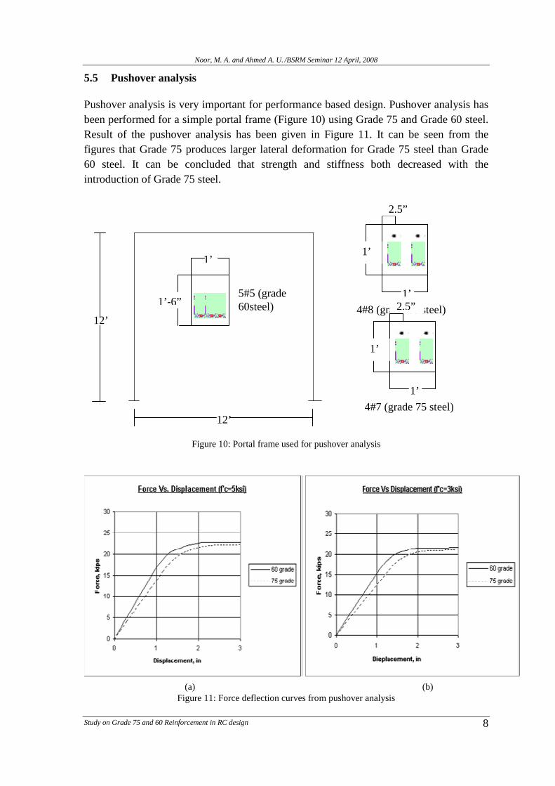
In civil construction a variety of materials are in competition and this is initiating a continuoustechnological innovation. This innovation not only concerns the improvement of the materials themselves,but also results in the introduction of new technologies and methods for fabrication, joining andconstruction. At present Grade 75 (75 ksi, 525 MPa) steel is available for structural construction. Instructural design the common practice is to use Grade 60. It is necessary to know about the advantages anddisadvantages of Grade 75 steel over Grade 60. A structural engineer should have adequate knowledgeabout effect of Grade 75 steel in reinforced concrete design for an efficient and economical design. In thispaper comparative study has been performed between Grade 75 and 60 steel for column and beam design.Column interaction diagrams and moment curvature diagrams have been drawn for same steel area forGrade 75 and 60 steel and with different concrete strength. Ultimate moment capacity of a beam section hasbeen compared for Grade 75 and 60 steel. Design charts have been produced for Grade 75 and 60 steel withdifferent steel ratio to have a clear idea about nominal moment capacity of rectangular section. From theserviceability point of view deflection controls the cross section area of a member. Deflection of a simplysupported beam designed with Grade 75 and 60 steel has been compared. Development length of Grade 75and 60 steel for different bar diameter have also been compared. Force-displacement characteristics of astructure are important for structural behavior under seismic load. Nonlinear pushover analysis has beenperformed for a portal frame designed with Grade 75 and 60 steel. A comparative study have beenperformed using Grade 75 and 60 steel to find the economical advantage, if any. It can be concluded thatGrade 75 steel gives higher moment capacity thus reducing reinforcement requirement but at the same timedeflection criterion must be taken care of. Ductility is less in higher grade steel than the lower grade.Concrete strength more than 4 ksi is recommended to get the full advantage of using Grade 75 steel.

Key words: Grade 75 and 60 steel, interaction diagram, moment curvature relation, ductility

1. Introduction

Steel has been established for more than 100 years as a construction material and the

Eiffel Tower in Paris is a world-wide recognized example demonstrating not only

impressively the merits of steel but also its impact on architectural creativity.

Probably the most relevant innovation for steel construction within the last century came

with the introduction of welding as the major joining technology. Furthermore, the

application of high strength steels supported the economics and the elegance of steel as

well as reinforced steel concrete constructions. High rise buildings, car park decks,

offshore platforms, ocean vessels, bridges, etc. demonstrate the widespread penetration of

steel into concrete construction engineering.

In civil construction a variety of materials are in competition and this is initiating a

continuous technological innovation. This innovation not only concerns the improvement

Noor, M. A. and Ahmed A. U. /BSRM Seminar 12 April, 2008

Study on Grade 75 and 60 Reinforcement in RC design 2

of the materials themselves, but also results in the introduction of new technologies and

methods for fabrication, joining and construction.

At present Grade 75 (75 ksi, 525 MPa) steel is available for structural construction. In

structural design the common practice is to use Grade 60. It is necessary to know about

the advantages and disadvantages of Grade 75 steel over Grade 60. A structural engineer

should have adequate knowledge about effect of Grade 75 steel in reinforced concrete

design for an efficient and economical design. In this paper comparative study has been

performed between Grade 75 and 60 steel for column and beam design.

Column interaction diagrams and moment curvature diagrams have been drawn for same

steel area for Grade 75 and 60 steel with different concrete strength. Ultimate moment

capacity of a beam section has been compared for Grade 75 and 60 steel. Design charts

have been produced for Grade 75 and 60 steel with different steel ratio to have a clear

idea about nominal moment capacity of rectangular section. From the serviceability point

if view deflection controls the cross section area of a member. Deflection of a simply

supported beam designed with Grade 75 and 60 steel has been compared. Development

length of Grade 75 and 60 steel for different bar diameter has also been compared. Force-

displacement characteristic of a structure is important for structural behavior under

seismic load. Nonlinear pushover analysis has been performed for a portal frame designed

with Grade 75 and 60 steel. A comparative study have done for Grade 75 and 60 steel to

find the economical advantage achieved from Grade 75 steel, if any.

2. Objectives

The main objectives of this study are(i) to compare the column interaction diagrams constructed using Grade 75 and 60

steel with varying the concrete strength,(ii) to find out the effect of Grade 75 steel over Grade 60 in beam moment capacity

and deflection,(iii) to compare the ductility between the two Grades.

3. Methodology

In this study ACI 2002 has been used code for every analysis. Deflection calculation is

based on assumption that section is cracked transformed. Moment curvature relationship

and nonlinear pushover analysis have been performed using finite element analysis

software named, OPENSEES (ver.1.7.5). Development length for different bar diameter

has been calculated using formula given in ACI 2002. The column design for the portal

frame to investigate economical benefit has been done with PCACOLUMN (ver. V2.2)

software.

4. Materials

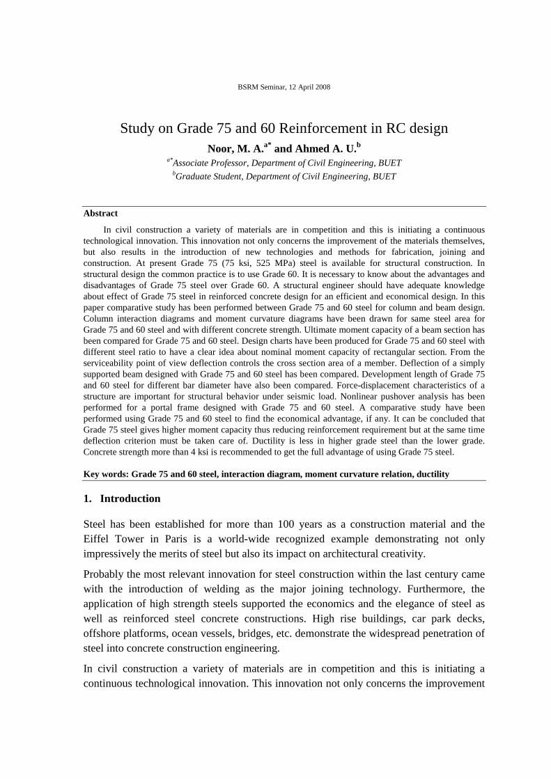
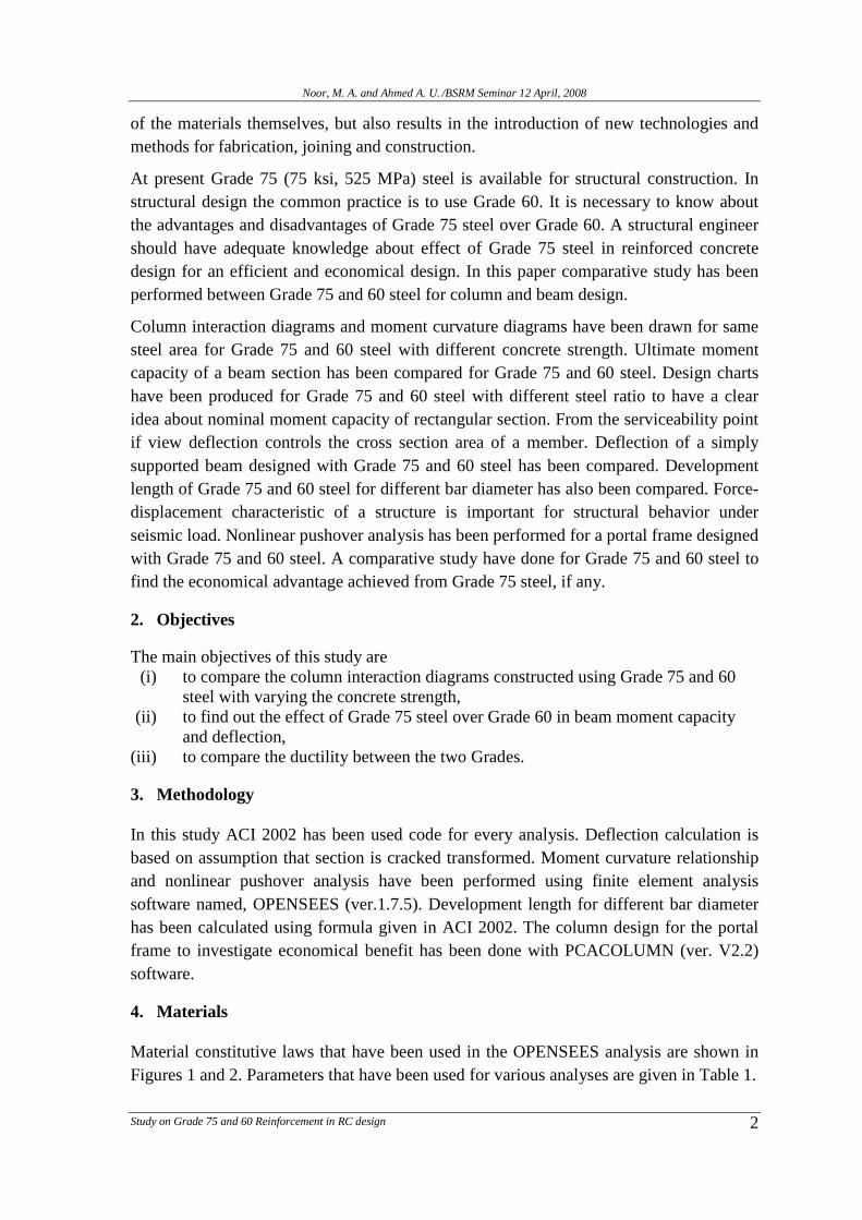
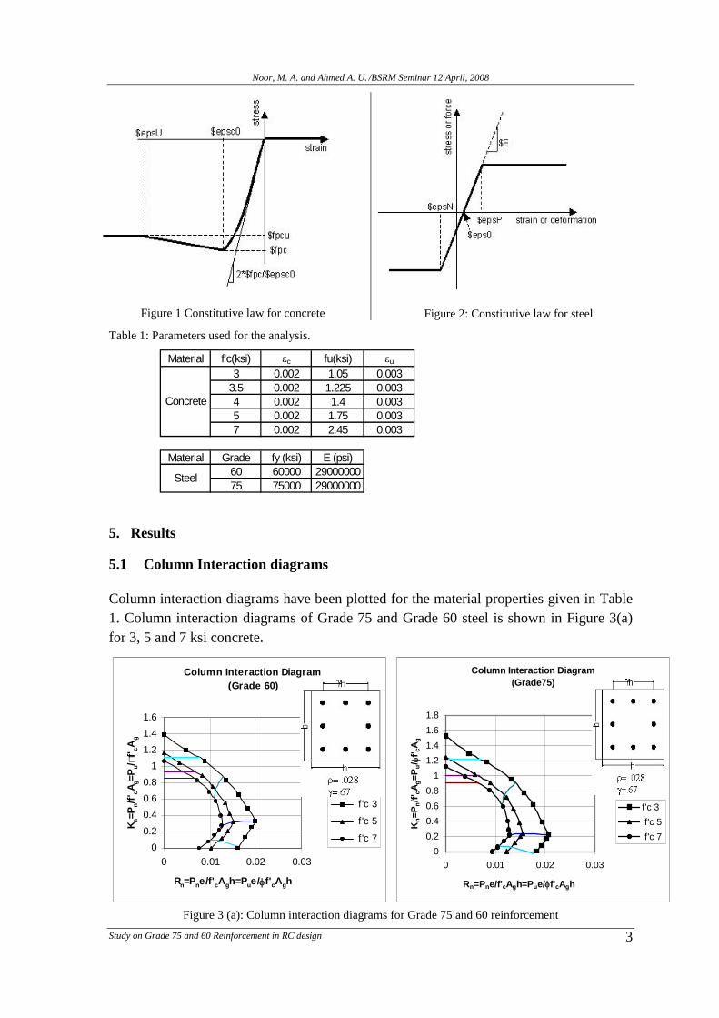
Material constitutive laws that have been used in the OPENSEES analysis are shown in

Figures 1 and 2. Parameters that have been used for various analyses are given in Table 1.

Noor, M. A. and Ahmed A. U. /BSRM Seminar 12 April, 2008

Study on Grade 75 and 60 Reinforcement in RC design 3

Figure 1 Constitutive law for concrete Figure 2: Constitutive law for steel

Table 1: Parameters used for the analysis.

Material f'c(ksi) c fu(ksi) u

3 0.002 1.05 0.003

3.5 0.002 1.225 0.0034 0.002 1.4 0.0035 0.002 1.75 0.003

7 0.002 2.45 0.003

Material Grade fy (ksi) E (psi)60 60000 29000000

75 75000 29000000

Concrete

Steel

5. Results

5.1 Column Interaction diagrams

Column interaction diagrams have been plotted for the material properties given in Table

1. Column interaction diagrams of Grade 75 and Grade 60 steel is shown in Figure 3(a)

for 3, 5 and 7 ksi concrete.

Figure 3 (a): Column interaction diagrams for Grade 75 and 60 reinforcement

Column Interaction Diagram

(Grade 60)

0

0.2

0.4

0.6

0.8

1

1.2

1.4

1.6

0 0.01 0.02 0.03

Rn=Pne/f'cAgh=Pue/f'cAgh

Kn=P

n/f

' cA

g=P

u/

f'cA

g

f 'c 3

f'c 5

f'c 7

Column Interaction Diagram

(Grade75)

0

0.2

0.4

0.6

0.8

1

1.2

1.4

1.6

1.8

0 0.01 0.02 0.03

Rn=Pne/f'cAgh=Pue/f'cAgh

Kn=

Pn/f

' cA

g=

Pu/

f'cA

g

f'c 3

f'c 5

f'c 7

Noor, M. A. and Ahmed A. U. /BSRM Seminar 12 April, 2008

Study on Grade 75 and 60 Reinforcement in RC design 4

Designers need uni-axial column interaction curves for column design. Currently no

column interaction diagrams are available for Grade 75 steel. In this paper efforts have

been made to prepare some column interaction charts for designers. Some typical design

charts for uni-axial column design are given below (Figure 3(b)). Complete charts will be

published in next publication.

Figure 3 (b): Column interaction diagrams for Grade 75 and 60 reinforcement

Interaction diagram

f'c=4 ksi, fy=75ksi

t=0.002

fs=fy

t=0.005

g

g=0.02

g=0.03

g=0.04

fs=0

0

0.2

0.4

0.6

0.8

1

1.2

1.4

1.6

0 0.05 0.1 0.15 0.2 0.25 0.3

Rn=Pne/f'cAgh=Pue/f'cAgh

Kn=

Pn/f

' cA

g=

Pu/ f

f'cA

g

Interaction diagram

f'c=4 ksi, fy=75ksi

=0.80

fs=fy

t=0.002

t=0.005

g=0.01

g=0.02

g=0.04

g=0.03

fs=0

0

0.2

0.4

0.6

0.8

1

1.2

1.4

1.6

0 0.05 0.1 0.15 0.2 0.25 0.3 0.35

Rn=Pne/f'cAgh=Pue/f'cAgh

Kn=

Pn/f

' cA

g=

Pu/ f

f'cA

g

Interaction diagram

f'c=4 ksi, fy=75ksi

=0.90

t=0.002

fs=fy

t=0.005

g=0.01

g=0.02

g=0.03

g=0.04

fs=0

0

0.2

0.4

0.6

0.8

1

1.2

1.4

1.6

0 0.05 0.1 0.15 0.2 0.25 0.3 0.35

Rn=Pne/f'cAgh=Pue/f'cAgh

Kn=

Pn/f

' cA

g=

Pu/ f

f'cA

g

Noor, M. A. and Ahmed A. U. /BSRM Seminar 12 April, 2008

Study on Grade 75 and 60 Reinforcement in RC design 5

Same interaction diagram have been redrawn to compare the difference between Grade 75

and Grade 60 steel for a particular concrete strength. Capacity of column increases if

Grade 75 steel is used (Figure 4). From these figure very little benefit will be derived if

the column has been design near the balanced steel ratio.

(a) (b)

(c)

Figure 4: Variation of column interaction diagram for Grade 75 and 60 reinforcement using differentconcrete strength

5.2 Congestion relief

So far, the main demand for high strength reinforcing steel has been in seismic areas on

the West Coast of USA where congestion (Figure 5) issues, especially at beam-column

intersections continue to plague rebar placing and design. A recent 31-story condominium

project in Seattle proved the potential benefits of 100 ksi reinforcing steel in just such a

situation. “Typical spacing of the confinement steel in the columns is 4 to 5 inches using

standard Grade 60 #4 bars,” says Brian Booth of Harris Rebar Seattle Inc., Tacoma,

Interaction Diagram for different Grade

Reinforcement (f'c=3 ksi)

0

0.2

0.4

0.6

0.8

1

1.2

1.4

1.6

0 0.01 0.02 0.03

Kn=P

n/f

' cA

g=P

u/

f'cA

g

60 grade

75 grade

Rn=Pne/f'cAgh=Pue/f'cAgh

Interaction Diagram for different Grade

Reinforcement (f'c=5 ksi)

0

0.2

0.4

0.6

0.8

1

1.2

1.4

1.6

0 0.005 0.01 0.015 0.02

Kn=P

n/f

' cA

g=P

u/

f'cA

g

60 grade

75 grade

Rn=Pne/f'cAgh=Pue/f'cAgh

Interaction Diagram for different Grade

Reinforcement (f'c=7 ksi)

0

0.2

0.4

0.6

0.8

1

1.2

1.4

1.6

0 0.005 0.01 0.015

Kn=

Pn/f

' cA

g=

Pu/

f'cA

g

60 grade

75 grade

Rn=Pne/f'cAgh=Pue/f'cAgh

Noor, M. A. and Ahmed A. U. /BSRM Seminar 12 April, 2008

Study on Grade 75 and 60 Reinforcement in RC design 6

Wash. “This creates severe congestion issues at the intersection areas. By switching to #5

bars made of Grade 100 steel, the spacing increased to between 8 to 12 inches, allowing

faster construction and easier placement of the concrete.”

Figure 5: Reinforcement congestion relief

5.3 Moment Capacity

Variation of Moment capacity has also been computed using Grade 75 and 60 steel.

Figure 6 shows the ultimate moment capacity of rectangular beam designed with different

grade steel and different concrete strength. It has been found that moment capacity is

increased significantly.

Figure 6: Moment capacity for rectangular beam using Grade 75 and 60 reinforcement

From Figure 7 it can be observed that for same percentage of steel beam with Grade 75

gives higher R value than Grade 60 steel, which will eventually reduce the steel

Ultimate Moment Capacity for

Different Grade Reinforcement

0

500

1000

1500

2000

2500

3000

0 2 4 6 8

f'c (kips)

mo

men

t(k

ips-i

n)

grade 60

grade 75

Noor, M. A. and Ahmed A. U. /BSRM Seminar 12 April, 2008

Study on Grade 75 and 60 Reinforcement in RC design 7

requirement if the depth of the beam kept constant. It has been observed that due to less

steel area requirement the deflection may increase.

Figure 7: R value for Grade 75 and 60 reinforcement

5.4 Deflection of Beam

For the beam shown in Figure 8 deflection at ultimate stage has been calculated using

OPENSEES. The simply supported beam has been used for calculate deflection. Figure 9

shows the variation of deflection for Grade 75 and Grade 60 steel. The comparison shows

that deflection is higher when Grade 75 steel is used.

Figure 8: Schematic of beam used for deflection calculation

.

Figure 9: Beam deflection

Moment Capacity of

Rectangular Section

0

100

200

300

400

500

600

700

0 0.005 0.01 0.015

= As/bd

R=

Mn/b

d2,

psi

grade 75 f'c 3ksi

grade 75 f'c 5ksi

grade 75 f'c 7ksi

grade 60 f'c 3ksi

grade 60 f'c 5ksi

grade 60 f'c 7ksi

Variation of Deflection for 60 & 75 grade

reinforcement and Different f'c

0

0.2

0.4

0.6

0.8

1

1.2

0 2 4 6 8

f'c, ksi

Defl

ecti

on

,in

60(aci)

75(aci)

60(opensees)

75(opensees)

Noor, M. A. and Ahmed A. U. /BSRM Seminar 12 April, 2008

Study on Grade 75 and 60 Reinforcement in RC design 8

5.5 Pushover analysis

Pushover analysis is very important for performance based design. Pushover analysis has

been performed for a simple portal frame (Figure 10) using Grade 75 and Grade 60 steel.

Result of the pushover analysis has been given in Figure 11. It can be seen from the

figures that Grade 75 produces larger lateral deformation for Grade 75 steel than Grade

60 steel. It can be concluded that strength and stiffness both decreased with the

introduction of Grade 75 steel.

Figure 10: Portal frame used for pushover analysis

(a) (b)Figure 11: Force deflection curves from pushover analysis

12’

1’

1’-6”5#5 (grade60steel)

12’4#8 (grade 60 steel)

1’

1’

2.5”

4#7 (grade 75 steel)

1’

1’

2.5”

Noor, M. A. and Ahmed A. U. /BSRM Seminar 12 April, 2008

Study on Grade 75 and 60 Reinforcement in RC design 9

5.6 Development Length

Figure 12(a) and Figure 12(b) show the difference in development length for Grade 75

and 60 steel having different bar diameter. Development length for Grade 75 steel is

higher than development length for Grade 60.

(a) (b)

Figure 12: Development length diagrams for Grade 75 and 60 reinforcement

5.7 Moment Curvature Relationship

Moment curvature relationship (Figure 13) for a particular cross section is very important

because information of ductility can be inferred from that. It can be said from the figure

that ductility increases with the increase of concrete strength. Low grade concrete

behaves poorly with high grade steel.

Figure 13: Moment curvature diagrams for Grade 75 and 60 reinforcement

Moment Curvature Relationship (grade 75)

f 'c=7ksi

f 'c=5ksif 'c=4ksi

f 'c=3.5ksif 'c=3ksi

0

500

1000

1500

2000

2500

3000

3500

0.0000 0.0002 0.0004 0.0006 0.0008 0.0010

Curvature,

Mo

men

t(k

ips-i

n)

Moment Curvature Relationship (grade 60)

0

f'c=5ksi f'c=7ksif'c=4ksi

f'c=3.5ksif'c=3ksi

0

500

1000

1500

2000

2500

0.0000 0.0003 0.0005 0.0008 0.0010 0.0013 0.0015

Curvature,

Mo

men

t(k

ips-i

n)

Noor, M. A. and Ahmed A. U. /BSRM Seminar 12 April, 2008

Study on Grade 75 and 60 Reinforcement in RC design 10

Figure 14: Moment curvature diagrams for Grade 75 and 60 reinforcement

Moment Curvature Relationship (f'c=3 ksi)

0

500

1000

1500

2000

2500

3000

0.0000 0.0001 0.0002 0.0003 0.0004 0.0005

Curvature,

Mo

men

t(k

ips-i

n)

grade 60

grade 75

Moment Curvature Relationship (f'c=7 ksi)

0

500

1000

1500

2000

2500

3000

3500

0.0000 0.0003 0.0006 0.0009 0.0012

Curvature,

Mo

men

t(k

ips-i

n)

grade 60

grade 75

Moment Curvature Relationship (f'c=5 ksi)

0

500

1000

1500

2000

2500

3000

3500

0.0000 0.0002 0.0004 0.0006 0.0008

Curvature,

Mo

men

t(k

ips-i

n)

grade 60

grade 75

Moment Curvature Relationship (f'c=3.5 ksi)

0

500

1000

1500

2000

2500

3000

0.0000 0.0002 0.0004 0.0006

Curvature,

Mo

men

t(k

ips-i

n)

grade 60

grade 75

Moment Curvature Relationship (f'c=4 ksi)

0

500

1000

1500

2000

2500

3000

0.0000 0.0002 0.0004 0.0006 0.0008

Curvature,

Mo

men

t(k

ips-i

n)

grade 60

grade 75

Noor, M. A. and Ahmed A. U. /BSRM Seminar 12 April, 2008

Study on Grade 75 and 60 Reinforcement in RC design 11

From Figure 14 it can be said that for any concrete grade, high grade steel (Grade 75)

gives lower ductility than low grade steel (Grade 60).

5.8 Economic Benefit

5.8.1 Column

To investigate economic benefit from Grade 75 steel, a column section having dimension

of 12x12 in has been designed for factored moment Mu =30 kips-ft and a factored load Pu

= 330 kips with both Grade 75 and 60 steel. The steel requirement has been found 4#8 bar

for Grade 60 steel and 4#7 bar for Grade 75 steel (Figure 15)

Figure 15: Cross section used for beam design

The ratio of reinforcement required by Grade 75 to 60 = (.79*4/.6*4)

= 0.76 =76%

i.e. steel required by Grade 75 is 76% of steel required by Grade 60 steel.

5.8.2 Beam

For a beam it is known that, Mn = As * fy * (d-a/2)

Beam with Grade 60 steel,

Mn = As60 * fy60 * (d-a/2) (1)

Beam with Grade 75 steel,

Mn = As75 * fy75 * (d-a/2) (2)

From Equation (1) and (2)

As75 = ( fy60/ fy75) * As60

As75 = 0.8*As60

It can be said ignoring all other requirement, only from flexural requirement 20% steel

can be saved by using Grade 75 steel.

6. CONCLUSIONS

It has been found that Grade 75 steel have some advantages over Grade 60 steel except in

development length and deflection of beam and ductility. Economy may also be achieved

4#7 (grade 75 steel)

1’

1’

2.5”

4#8 (grade 60 steel)

1’

1’

2.5”

Noor, M. A. and Ahmed A. U. /BSRM Seminar 12 April, 2008

Study on Grade 75 and 60 Reinforcement in RC design 12

by using Grade 75 steel. Main advantage of using Grade 75 steel is to remove the steel

congestion at beam column joint. To get maximum benefits from Grade 75 steel good

engineering judgments are required. Steel is a very versatile material for construction.

With increasing yield strength of material cost reductions can be achieved for high rise

buildings. Low rise buildings may not produce cost reduction using Grade 75 steel.

Another important factor is concrete strength. Concrete strength more 4 ksi is

recommended to achieve the added benefit by introducing the Grade 75 steel. Proper

supervision in the concrete construction site is required for these purposes. These benefits

can be applied only if the construction is safe. Actual design codes allow safety

considerations to avoid brittle fracture based on fracture mechanics and using small test

samples.


Recommended