Study On The Edge Defects of High Volume Fraction 70% SiCp/Al Composites In Ultrasonic-Assisted Milling Peicheng Peng Henan Polytechnic University Daohui Xiang ( [email protected]) Henan Polytechnic University https://orcid.org/0000-0002-3811-210X Xiaofei Lei Henan Polytechnic University Zhanli Shi Henan Polytechnic University Bo Li Henan Polytechnic University Gaofeng Liu Henan Polytechnic University Bo Zhao Henan Polytechnic University Guofu Gao Henan Polytechnic University Research Article Keywords: 70% SiCp/Al composites, ヲnite element simulation, edge defects, ultrasonic-assisted milling Posted Date: August 17th, 2021 DOI: https://doi.org/10.21203/rs.3.rs-782256/v1 License: This work is licensed under a Creative Commons Attribution 4.0 International License. Read Full License
Transcript
Study On The Edge Defects of High Volume Fraction70% SiCp/Al Composites In Ultrasonic-AssistedMillingPeicheng Peng
Abstract Directing at the hard machinability of high volume fraction 70% SiCp/Al composites,
a longitudinal and torsional ultrasonic-assisted milling method is proposed to improve the edge quality and machining efficiency. By observing the metallographic structure of the material, the three-dimensional finite element model of SiC particles with spherical, ellipsoidal and random polyhedra is established and analyzed by ABAQUS simulation software. The formation mechanism of edge defects, stress distribution, defect characteristics and the effect of machining parameters on milling force are investigated during ultrasonic-assisted milling. The results show that the edge defects appear at the inlet, outlet and middle edge position, especiallyis more serious at the outlet position. The SiC particles failure modes mainly include particle pullout, particle shearing, crushing, and the edge defects mainly include matrix tearing, edge breakage, burrs, bulgesandpits. In a certain range of ultrasonic amplitude, ultrasonic-assisted milling can effectively reduce the surface fragmentation rate and milling force, slow down the expansion of cracks, increase the plastic flow of material, and obtain better edge quality compared with traditional machining method. By comparing the results of finite element simulation and experimental tests, it shows that the simulation results are in good agreement with the experimental tests. Keywords: 70% SiCp/Al composites﹒finite element simulation﹒edge defects﹒ultrasonic-assisted milling
1 Introduction
SiCp/Al composites own excellent properties of high specific strength, specific stiffness, specific modulus, good wear resistance and low heat expansion coefficient. So they are widely used in military, aerospace and electronic packaging [1-4]. However, It’s difficult to machine because SiCp/Al composites have high brittleness and low toughness. SiCp/Al composites are machined by traditional machining methods with low processing efficiency, poor surface quality, and edge defects such as spalling, edge collapse, burr and fragmentation are easy to appear at the end of workpiece [5-6]. These irreparable defects seriously affect the accuracy of the workpiece, which greatly increases the processing cost [7]. Therefore, how to obtain reduce edge defects and high quality surfaces for high volume fraction SiCp/Al composites is a crucial issue to be solved during machining.
In recent years, some scholars have done a lot of research on the edge defects. G.L.
Chern et al. [8] discovered that the burr formation mainly occured in the material with strong plasticity and the fracture surface of the plastic material was accompanied by pits, while the fracture surface is formed at the exit of the material with high hardness through orthogonal cutting experiments on aluminum materials. G. Mathai et al. [9] explored the process of abrasive-assisted brush milling deburring on steel and copper, and founded that the burr removal rate and initial height of the burr increased with increasing spindle speed. I.S.Shyha et al[10]. founded that crown burrs appeared at the exit of the hole when rotating at high speed and using spray by drilling experiments on stacks of carbon fiber metal matrix composites. Based on scholars' research on machining mechanism and machining parameters, many non-traditional processing methods have emerged to improve the quality of edges, including ultrasonic-assisted machining [11-12], laser machining [13-14] etc. The difference between ultrasonic-assisted machining and traditional machining is that periodic ultrasonic vibrations are applied to the tool or workpiece, then the tool and workpiece produce periodic separation, which is more commonly used in hard and brittle materials and other difficult machining materials. P. Feng et al. [15] effectively reduced the substrate tear area by rotary ultrasound-assisted drilling for C/Sic materials. C. Ma et al. [16] built a theoretical model and verified that the height of burrs can be reduced by using ultrasonic elliptical vibration cutting. In addition, finite element simulation has been a hot spot as an important guide in the actual research work. L.Zhou et al. [5] discovered that the fracture surface at the exit was very rough and the SiC particles occurred brittle fracture by two-dimensional orthogonal finite element simulation and experiments. B. Zhang et al. [17] founded that the exit burrs and cracks were mainly distributed in the regions corresponding to the shear angles of 90°and 0° by three-dimensional finite element simulation of carbon fiber composite materials. A.K.Yadav et al. [18] conducted finite element simulation and experimental research on Ti6Al4V material, and founded that the burr height can be predicted through two-dimensional Finite element simulation.
From the above study on edge defects, it can be seen that there are more researches
on the burrs phenomenon in plastic materials and low volume fraction SiCp/Al composites, while less researches on the mechanism and characteristics of ultrasonic-assisted milling of high volume fraction 70% SiCp/Al composites. Moreover, the finite element simulation mode built mainly focuses on two-dimensional and three-dimensional of homogeneous materials, while there are few researches on three-dimensional of heterogeneous materials. Since SiCp/Al composites are composed of SiC particles and aluminum matrix, the interaction between SiC particles and aluminum matrix and the fracture of SiC particles should be considered. In this paper, a three-dimensional finite element model was built with enhanced phase shape of sphere, ellipsoid, and random polyhedron by ABAQUS simulation software for the practical need of machining process and to find a better way to control edge defects. The edge defects forming process and the effect of machining parameters on milling force for 70% SiCp/Al composite material were investigated during ultrasonic-assisted milling through Finite element simulation. Finally, the simulation results are compared with the experimental results. By studying the edge defects forming process, this paper found the formation mechanism of edge defects and proposed a method to improve the quality of edge and the efficiency of processing.
2 Finite element simulation of longitudinal and torsional ultrasonic-
assisted milling
2.1 Mechanism of longitudinal and torsional ultrasonic-assisted milling
The principle of ultrasonic vibration cutting refers to the application of ultrasonic vibration on the basis of traditional machining. Periodic vibration is usually applied to the tool or workpiece to meet the needs of ultra-precision machining. However, no matter what direction of vibration is applied, it can be seen as a simple harmonic motion on the tool. Longitudinal and torsional ultrasonic-assisted is to exert the same frequency of circumferential torsional vibration based on longitudinal ultrasonic vibration. Fig.1 is a schematic diagram of longitudinal torsion ultrasonic-assisted milling.
Fig. 1 Schematic diagram of longitudinal and torsional ultrasonic-assisted milling
As follows, according to the traditional milling cutting edge motion trajectory equation, the trajectory equation is obtained by applying longitudinal and torsional ultrasonic vibration in Eq. (1):
In the formula, vf is the feed speed of the milling cutter, r is the radius of the cutter, n is the speed of the milling cutter, f is the frequency of the ultrasonic vibration, and 𝐴1, 𝜑1 are respectively the amplitude and initial phase of the longitudinal ultrasonic vibration, and 𝐴2, 𝜑2 are respectively the amplitude and initial phase of the torsional ultrasonic vibration.
As shown in Fig. 2, the cutter of longitudinal and torsional vibrationis periodically separated from the workpiece, which can reduce the extrusion of the flank face on the machined surface. So it effectively reduces the cutting force and improves the machining quality.
Fig. 2 Cutter point trajectory of longitudinal and torsional vibration-assisted milling
2.2 Finite element simulation model
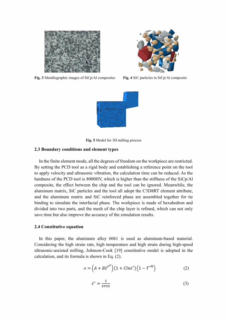
Fig. 3 shows the microstructure of high volume fraction 70% SiCp/Al composite with the size of 20×15×10mm3. By comparing the shape and distribution of SiC particles in the metallographic photos of SiCp/Al composite, the model of SiC particles showed in Fig.4 is established for reflecting the actual machining process and the stress change. The volume of reinforced SiC particles accounts for 70% of the composite, and the average diameter is 45μm . The SiC particles are randomly distributed in the aluminum matrix material, and the reinforced phase can be penetrated. Meanwhile, the boundary conditions are defined as periodic boundary conditions. Fig. 5 shows the model of 3D milling process, where the main shapes of the model reinforcing phase SiC are 24-sided, 12-sided, spherical, and ellipsoidal.
Fig. 3 Metallographic images of SiCp/Al composites Fig. 4 SiC particles in SiCp/Al composite
Fig. 5 Model for 3D milling process
2.3 Boundary conditions and element types
In the finite element mode, all the degrees of freedom on the workpiece are restricted. By setting the PCD tool as a rigid body and establishing a reference point on the tool to apply velocity and ultrasonic vibration, the calculation time can be reduced. As the hardness of the PCD tool is 8000HV, which is higher than the stiffness of the SiCp/Al composite, the effect between the chip and the tool can be ignored. Meanwhile, the aluminum matrix, SiC particles and the tool all adopt the C3D8RT element attribute, and the aluminum matrix and SiC reinforced phase are assembled together for tie binding to simulate the interfacial phase. The workpiece is made of hexahedron and divided into two parts, and the mesh of the chip layer is refined, which can not only save time but also improve the accuracy of the simulation results.
2.4 Constitutive equation
In this paper, the aluminum alloy 6061 is used as aluminum-based material. Considering the high strain rate, high temperature and high strain during high-speed ultrasonic-assisted milling, Johnson-Cook [19] constitutive model is adopted in the calculation, and its formula is shown in Eq. (2).
𝜎 = (𝐴+𝐵�̅�𝑃𝑁) (1+ 𝐶𝑙𝑛�̇�∗) (1 − 𝑇∗𝑀) (2)
𝜀̇∗ = �̇̅�𝐸𝑃𝑆𝑂 (3)
𝑇∗ = 𝑇−𝑇𝑟𝑜𝑜𝑚𝑇𝑚𝑒𝑙𝑡−𝑇𝑟𝑜𝑜𝑚
(4)
Where 𝜎 is the yield stress, EPSO is the reference strain rate. A is the initial yield stress, B is the stress hardening constant, ε̇∗is the effective total strain rate, N is the stress hardening index, M is the strain rate constant, 𝐶 is the softening index, 𝑇∗ is the specific temperature, 𝜀�̅� is the effective plastic strain, 𝑇𝑟𝑜𝑜𝑚 is the room temperature.
The fracture strain of the material should be considered in the cutting process [20]: 𝑒𝑓 = max([𝐷1 + 𝐷2𝑒𝑥𝑝𝐷3𝜎∗][1 + 𝐷4𝑙𝑛𝜀̇∗][1 + 𝐷5𝑇∗], 𝐸𝐹𝑀𝐼𝑁) (5) Where σ∗is the ratio of pressure to effective stress, D1~D5 is the fracture constant, EFMIN is the lower limit value of fracture strain calculation, ∆𝜀�̅�is the effective plastic
strain increment.
It will lead to fracture and chip separation of materials when the damage variable D reaches 1. The Damage parameter D is in Eq. (6), and ∆𝜀�̅� is the increment of effective plastic strain.
𝐷 = (∑∆𝜀�̅� )/𝜀𝑓 (6) Table1 shows that the material constants of johnson-Cook constitutive model for
aluminum alloy matrix, and Table 2 shows the damage parameters of johnson-Cook, Table 3 shows the material performance parameters and Table 4 shows the milling parameters.
Table1 Material constants of johnson-Cook constitutive model for aluminum alloy matrix
A(Mpa) B(Mpa) C n m
240 200 0.005 0.2 2
Table2 Damage parameters of Johnson-Cook
D1 D2 D3 D4 D5
-0.77 1.45 -0.47 0 1.60
Table 3 Performance parameters of materials used in milling simulation
Table4 Cutting parameters used in milling experiments
Parameter Numerical value
Vertical amplitude(um) 0, 1.5, 2.5, 3.5, 4.5
Torsion amplitude(um) 0,1, 1.7, 2.3, 3.1
Milling speed(m/min) 45, 75, 105, 135, 165
Feed rate(mm/z) 0.007, 0.009, 0.011, 0.013, 0.015
Depth of cut(mm) 0.1,0.3,0.5,0.7,0.9
PCD tool parameters
Rake angle 𝛾0 = 5°, Tool clearance 𝛼0 = 10°,
Teeth Z=2, Cutter diameter D=8mm
3 Experiment procedures
The validity of the finite element mode is verified through experiments. The entire test process of longitudinal and torsion ultrasonic-assisted milling of SiCp/Al composite material is completed on a VMC850E three-axis vertical machining center. The PCD tool is used to milling SiCp/Al composite materials and the experimental parameters are consistent with the simulation parameters. The device of force measuring is a Kistler 9257B triaxial dynamometer. The microscopic morphology of the edge defects is observed by scanning electron microscopy.
Fig. 6 Experiment setup
4 Results and analysis
4.1 Formation mechanism and stress distribution of edge defects during machining
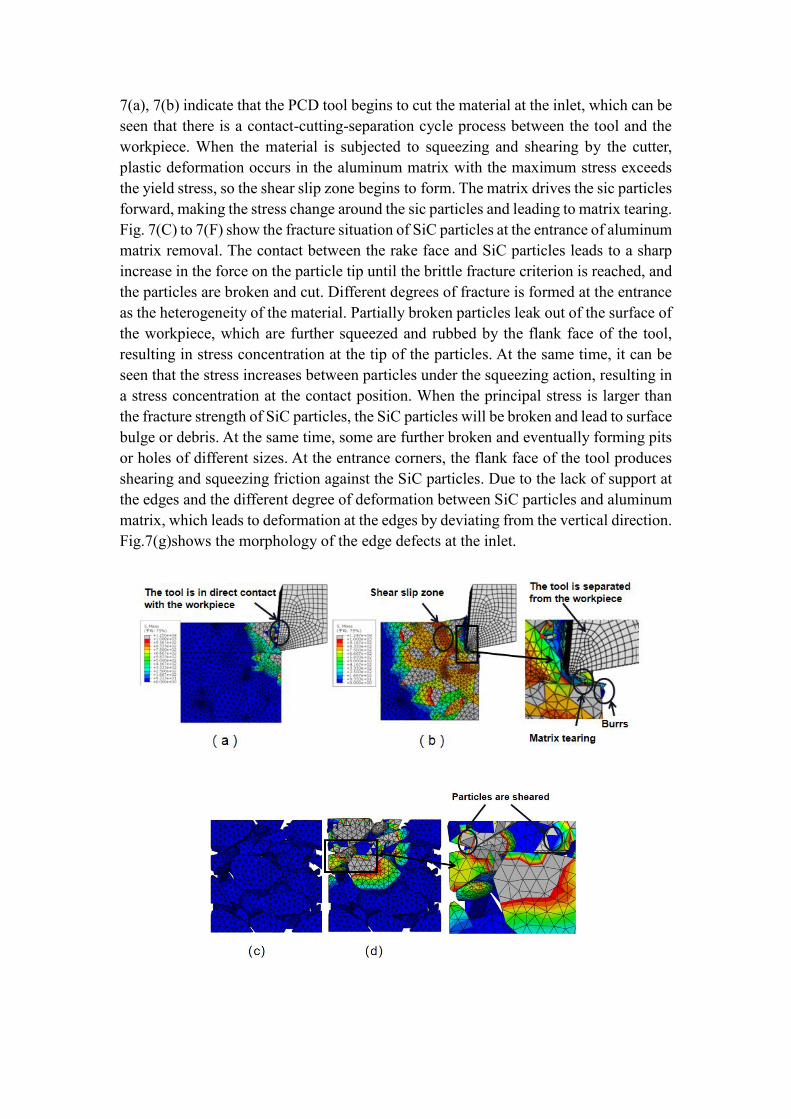
Fig. 7 shows the generation of edge defects at the inlet in the process of ultrasonic- assisted milling. In the milling process, the machining parameters are the milling depth of 0.5 mm, the feed rate of 0.007 mm/Z, the milling speed of 135 m/min, the ultrasonic longitudinal amplitude of 2.5 um and corresponding torsional amplitude of 1.7 um. Fig.
7(a), 7(b) indicate that the PCD tool begins to cut the material at the inlet, which can be seen that there is a contact-cutting-separation cycle process between the tool and the workpiece. When the material is subjected to squeezing and shearing by the cutter, plastic deformation occurs in the aluminum matrix with the maximum stress exceeds the yield stress, so the shear slip zone begins to form. The matrix drives the sic particles forward, making the stress change around the sic particles and leading to matrix tearing. Fig. 7(C) to 7(F) show the fracture situation of SiC particles at the entrance of aluminum matrix removal. The contact between the rake face and SiC particles leads to a sharp increase in the force on the particle tip until the brittle fracture criterion is reached, and the particles are broken and cut. Different degrees of fracture is formed at the entrance as the heterogeneity of the material. Partially broken particles leak out of the surface of the workpiece, which are further squeezed and rubbed by the flank face of the tool, resulting in stress concentration at the tip of the particles. At the same time, it can be seen that the stress increases between particles under the squeezing action, resulting in a stress concentration at the contact position. When the principal stress is larger than the fracture strength of SiC particles, the SiC particles will be broken and lead to surface bulge or debris. At the same time, some are further broken and eventually forming pits or holes of different sizes. At the entrance corners, the flank face of the tool produces shearing and squeezing friction against the SiC particles. Due to the lack of support at the edges and the different degree of deformation between SiC particles and aluminum matrix, which leads to deformation at the edges by deviating from the vertical direction. Fig.7(g)shows the morphology of the edge defects at the inlet.
Fig. 7 Defect formation process of inlet edge defects
Fig.8 shows that the shear zone undergoes plastic deformation and continues to extend forward, which is combined with the plastic zone on the middle edge location of the workpiece. The two stresses concentrates together under shear and extrusion by the rake face, resulting in matrix tearing of the substrate. Some of the particles are separated and broken in the form of chips, and some of the particles are exposed, which are cut by the rake face or squeezed and rolled by the flank face, leading to particle crushing and material failure around the particles. Then it forms pits and bulges of different sizes. Edge defects begin to form on the middle edge of the material.
Fig. 8 Defect formation process of middle edge
Fig. 9 shows the formation of edge defects at the exit. It can be seen from Fig.(9a) that the maximum stress is concentrated at the lower left and front lower positions of the milling tool, which deviates from the milling position of the milling tool, and the stress around the particles is the largest. Fig.(9b)shows that the bonding surface between the matrix interface and the SiC reinforcement particles produces slipping deformation. The workpiece lacks support position,so it can no longer withstand the stress and the material breaks at the exit. Fig.(9c)hides off the aluminum substrate. It can be seen that the maximum stress is concentrated between the particles , and there is extrusion crushing between the particles, which leads to the failure of the materials surrounding of the particles and finally debonding. The whole grain appears to be peeled off at the edge, forming a wide range of fractures with a large fracture depth and some chips left on the surface of the workpiece. As shown in Fig.(9e), an obvious separation interface is formed. Due to the random distribution of particles, the stress at the outlet is different, which leads to different sizes of pits.
The edge defects appeared at the inlet, outlet and middle edge, and were more serious at the outlet. The particle failure modes mainly include particle pullout, particle shearing, crushing, and the edge defects mainly include matrix tearing, chipping, burrs, bumps, pits, etc.
Fig. 9 Defect formation process of outlet edge
4.2 Milled surface topography
In order to verify the simulation results and compare the effects of different ultrasonic machining parameters on the formation of edge defects, the ultrasonic longitudinal amplitudes are selected as 0um and 2.5um, and the torsional amplitudes are selected as 0um and 1.7um, respectively. The other machining parameters are consistent with the simulation parameters. The experimental machining results are observed by scanning electron microscope (SEM). Fig.(10a),10(b) show the morphology of ultrasonic-assisted machining and ordinary machining morphology at the inlet edges and tips, respectively. There are matrix tears, cracks, small cracks and pits at the inlet. However, the entrance of ultrasonic-assisted milling is relatively flat, and the damage size is smaller than ordinary milling. In addition to these characteristics, the form of the material breakage is mainly the toughness breakage and the size of the SiC particles broken is mainly the small particles at the fracture location. But a phenomenon of over-cutting at the top corners has appeared in ordinary machining, causing large pieces of the top to fall off. At the same time, there are burrs, particle pressing, large crack, overall particle pulling out and overall particle shearing appeared, resulting in the edge defects at the inlet. It is proved that ultrasonic assisted milling can restrain the appearance of burrs and cracks and reduce the entrance impact force.
Fig .10 Microstructure at the inlet
Fig. 11(a) and 11(b) show the micro-morphology of middle position in ultrasonic- assisted machining and ordinary machining respectively, both of which form pits of different sizes. The edge is flatter and the material removal method is mainly plastic removal in ultrasonic-assisted milling. However, it has large plastic bumps and pits caused by large particle fractures in ordinary milling, accompanied with burrs and large cracks. This is due to the high temperature during the machining process and the large thermal deformation caused by ordinary milling. But the high-frequency vibration of ultrasonic-assisted milling reduces the plastic deformation and enhances the plastic flow, which improves the ductility of the material and reduces the large gap caused by the matrix debonds.
Fig.11 Microstructure at the middle edge
Fig. 12(a) and 12(b) show the micro-morphology of outlet position in ultrasonic- assisted milling and ordinary milling respectively. Both of which form a whole edge fracture, but the fracture depth of ordinary milling is larger and accompanied with debris and burrs. Since ultrasonic milling produces a large number of tiny cracks and powdering under high frequency hammering, less force is required to achieve material removal, thus reducing edge defects at the exit.
The results of edge defects appearing in the experiment are consistent with the simulation results. Compared with the ordinary cutting, the method of ultrasonic-assisted milling helps to suppress burrs and cracks generation and the material removal way is mainly plastic removal mode, which improves the quality of the edges. Therefore, it is necessary to study the effect of different ultrasonic machining parameters on the edge defects.
Fig.12 Microstructure at the outlet
4.3 Influence of machining parameters on cutting force
Since the cutting force is an important factor affecting the deformation and damage of the workpiece, this section explores the effect of machining parameters on the milling force, which indirectly responds to the degree of edge defect breakage and provides a basis for reducing edge defects. Fig. 13 shows that the comparison between the simulation and experiment values of axial force for conventional milling and ultrasonic-assisted milling with different machining parameters. It is found that the cutting force increases with the increase of feed rate and depth of cut; the cutting force first increases and then decreases with the increase of cutting speed. The workpiece becomes softening because of the rising temperature in the cutting zone at large cutting speeds, resulting in a reduction in cutting force. The cutting force first decreases and then increases with
the increase of ultrasonic amplitude. Because if the amplitude is too large, it will cause the tool vibrate strongly and the cutting force increases, resulting in more serious damage. Moreover, the ultrasonic-assisted cutting force is less than traditional machining, and the simulation value is less than the experiment value, because the tool is set as a rigid body in the simulation process and the tool wear is not considered. In addition, it is also affected by the experimental conditions. The error range between the experiment value and the simulation value is within 18%, so the simulation analysis can predict the force change in the actual machining process. In order to improve the quality of the edge, it is better to choose a small depth of cut and feed rate, choose a large cutting speed and appropriate ultrasonic amplitude in the actual machining process.
Fig. 13 Effects of machining parameters on milling forces
5 Conclusions
A three-dimensional finite element model of SiCp/Al composite with 70% volume fraction was established by ABAQUS simulation software, which used to investigate the formation mechanism of edge defects, stress distribution, defect characteristics and the effect of ultrasonic machining parameters on milling force during ultrasonic-assisted milling. Compared with the experimental results, these results agree well and the following conclusions are obtained.
1. Edge defects is found at the inlet, middle edge and outlet positions and the most severely broken at the outlet position. The inlet location mainly includes pits, holes,
matrix tearing, and the middle edge location mainly includes pits, bulges and other defects. These two positions are mainly subject to shear and squeeze by the tool and matrix tearing, resulting in particle shearing, breakage, crushing,pullout, etc. The outlet location contains large fracture edge collapse and ductile behavior accompanied by burrs, debris and so on, which mainly due to the stress concentration as it lacks of support at the outlet location.
2. By observing the microscopic morphology of the edge defects, the method of ultrasonic-assisted milling can effectively reduce the breakage size so that get a flatter surface and the broken SiC particles are mainly small particles compared to the traditional machining. As it enhances the plastic flow of the material and suppresses the length of burrs and cracks. While the main failure process of traditional machining mainly brittle fracture and the broken SiC particles are mainly large particle.
3. In a certain range of ultrasonic amplitude, ultrasonic-assisted milling can effectively reduce the milling force. The cutting force increases with the increase of cutting depth and feed rate; and the cutting force first increases and then decreases with the increase of cutting speed. Therefore, choosing small milling depth and feed rate, high milling speed and appropriate amplitude can effectively inhibit the edge defects during machining.
Author contribution Peicheng Peng: Methodology, Investigation, Formal analysis, Writing-review & editing. Daohui Xiang: Project administration, Formal analysis, Writing-review & editing. Xiaofei Lei: Data curation, Investigation. Zhanli Shi: Data curation, Investigation. Bo Li: Data curation, Investigation. Gaofeng Liu: Data curation, Investigation. Bo Zhao: Writing-review & editing. Guofu Gao: Writing-review & editing.
Funding We are very grateful to the National Natural Science Foundation of China (No. 5197052714) for their strong support.
Data availability The data that support the findings of this study are available from the corresponding author upon reasonable request.
Declarations
Ethical approval I would like to declare on behalf of my co-authors that the work described was application that has not been published previously, and not under consideration for publication elsewhere, in whole or in part.
Consent to participate All authors know and agree to be co-authors.
Consent to publish All authors agreed to be publish.
Conflict of interest The authors have declared that there are no conflicts of interest.
Reference
1. Chawla N, Shen YL (2001) Mechanical behavior of particle reinforced metal matrix composites. Advanced engineering materials, 3(6): 357-370
2. Basak AK, Pramanik A, Prakash C (2019) Deformation and strengthening of SiC reinforced Al-MMCs during in-situ micro-pillar compression. Materials Science and Engineering 763:138-141
3. Lu SJ, ZHANG JJ, Li ZQ, Zhang JG, Wang XH (2021) Cutting path-dependent machinability of SiCp/Al composite under multi-step ultra-precision diamond cutting. Chinese Journal of Aeronautics, 34(4): 241-252
4. Zhao G, Mao P, Li L, Lqbal A, Ning H (2020) Micro-milling of 65 vol% SiCp/Al composites with a novel laser-assisted hybrid process. Ceramics International 46(16): 26121-26128
5. Zhou L, Wang Y, Ma ZY, Yu XL (2014) Finite element and experimental studies of the formation mechanism of edge defects during machining of SiCp/Al composites. International Journal of Machine Tools and Manufacture, 84: 9-16
6. Kadivar M A, Akbari J, Yousefi R, Rahi A, Nick MG (2014) Investigating the effects of vibration method on ultrasonic-assisted drilling of Al/SiCp metal matrix composites. Robotics and Computer-Integrated Manufacturing 30(3): 344-350
7. Aurich JC, Dornfeld D, Arrazola PJ, et al (2009) Burrs—Analysis, control and removal. CIRP annals, 58(2): 519-542
8. Chern GL (2006) Study on mechanisms of burr formation and edge breakout near the exit of orthogonal cutting. Journal of Materials Processing Technology, 176(1-3): 152-157
9. Mathai G, Melkote S (2012) Effect of process parameters on the rate of abrasive assisted brush deburring of microgrooves. International Journal of Machine Tools and Manufacture 57: 46-54
10. Shyha IS, Soo SL, Aspinwall DK, Bradley S, Perry R, Harden Y, Dawson S (2011) Hole quality assessment following drilling of metallic-composite stacks. International Journal of Machine Tools and Manufacture, 51(7-8): 569-578
11. Bin F, Yuan ZH, Li DP, Gao LY (2021) Effect of ultrasonic vibration on finished quality in ultrasonic vibration assisted micromilling of Inconel718. Chinese Journal of Aeronautics, 34(6): 209-219
12. Wang JJ, Feng PF, Zheng JZ, Zhang JF (2016) Improving hole exit quality in rotary ultrasonic machining of ceramic matrix composites using a compound step-taper drill. Ceramics International 42(12): 13387-13394. 13. Zhang RH, Li WN, Liu YS, Wang CH, Wang J (2015) Machining parameter optimization of C/SiC composites using high power picosecond laser. Applied Surface Science, 330: 321-331
14. Liu YS, Wang CH, Li WN, Zhang LT, Yang XJ, Chen GH, ZHANG Q (2014) Effect of energy density and feeding speed on micro-hole drilling in C/SiC composites by picosecond laser. Journal of Materials Processing Technology 214(12): 3131-3140
15. Feng PF, Wang JJ, Zhang JF, Zheng JZ (2017) Drilling induced tearing defects in rotary ultrasonic machining of C/SiC composites. Ceramics International 43(1): 791-799
16. Ma CX, Shamoto E, Moriwaki T, Zhang YH, Wang LJ (2005) Suppression of burrs in turning with ultrasonic elliptical vibration cutting. International Journal of Machine Tools and
Manufacture45(11): 1295-1300
17. Zhang BY, Wang FJ, Wang Q, Zhao X (2021) Novel fiber fracture criteria for revealing forming mechanisms of burrs and cracking at hole-exit in drilling Carbon Fiber Reinforced Plastic. Journal of Materials Processing Technology 289: 116934
18. Yadav AK, Bajpai V, Singh NK, Singh RK (2017) FE modeling of burr size in high-speed micro-milling of Ti6Al4V. Precision Engineering 49: 287-292. 19. Johnson GR, Cook WH (1983) A constitutive model and data for metals subjected to large strains, high strain rates and high temperatures. Engineering Fracture Mechanics 21:541-548
20. Johnson GR, Cook WH (1985) Fracture characteristics of three metals subjected to various strains, strain rates, temperatures and pressures. Engineering fracture mechanics 21(1): 31-48


![SICP [SV-Series] User Manual - GPO Display](https://static.documents.pub/doc/80x56/6258237aefeefe074308e80b/sicp-sv-series-user-manual-gpo-display.jpg)


