1School of Civil Engineering and Architecture, Anhui University of Science and Technology, Huainan 232001, China
2Department of Mechanical Engineering, National Institute of Technology Silchar, Silchar 788010, India
Received 29 July 2018; Accepted 17 October 2018 ___________________________________________________________________________________________ Abstract
The horizontal stiffness of composite piles is an important factor influencing the horizontal bearing capacity of composite piles. However, this factor has been analyzed through field experiences rather than theoretically by other researchers. In this study, a calculation formula for analysis of this factor was deduced through an elastic–plasticity theoretical analysis. The formula was used to investigate influences of solidified soils on the horizontal stiffness and the bearing capacity of composite piles in accordance with stress mechanism under horizontal loads. Then, the differential equation of composite piles deflection under the combined stiffness was achieved. On this basis, a one-way cyclic loading test on six piles was performed on the site. Results demonstrate that solidified soil increases the combined stiffness of composite piles in the deformation process from elasticity to plasticity. The characteristic value and the ultimate value of single-pile horizontal bearing capacity in the composite piles are 1.81–2.62 and 2.00–2.25 times those of tubular pipes, respectively. When the length–diameter ratio of tubular pile is more than 27.5, the single-pile horizontal bearing capacity in the composite piles is less affected with the increase of length–diameter ratio of tubular piles. The accuracy of the theoretical analysis on the factor is further verified by the field test. The conclusions can serve as references for engineering design and further research of composite piles.
1. Introduction Soft soil strata are extensively distributed in the Yangtze River Delta and Pearl River Delta in China. They are characterized by high moisture content, high compressibility, low bearing capacity, and low permeability [1]. These characteristics often bring various problems in constructing on soft soil strata, such as serious subsidence and lengthy time requirement for reaching a stable state. To overcome these problems, soft soils are often stirred on site with cement slurry or powder to form solidified soil piles. This process can change the strength and the modulus of soft soils, thus solidifying soft soil strata [2]. With the development of construction equipment, solidified soil piles have been widely used to reduce settlement [3], reinforce slope [4], and stabilize foundations of embankment [5-6] because of their fast pile-forming and high construction efficiency. However, solidified soil piles show evident brittle behaviors in practical engineering. Although they can bear large vertical loads, they easily develop shearing failures under horizontal loads and lateral displacement. As a result, the construction effect of solidified soil piles is often restricted. Therefore, piles that suit solidified soil piles should be developed and combined into composite piles that can overcome brittle behaviors and poor horizontal bearing capacity.
As a kind of common precast piles, tubular piles have good quality, high strength, and small diameter [7-8]. When
tubular piles are used independently, the influences of soil plug effect and squeezing effect on bearing capacity of the pile body should be considered [9]. Tubular piles can cooperate with solidified soils to form composite piles due to their hollow structure. Composite piles are convenient to exert high compressive strength of solidified soils and conducive to exert high flexural strength of tubular piles for improving brittle behaviors of solidified soil piles. Existing studies on the horizontal bearing capacity of solidified soil–tube composite piles are based on empirical formula and field investigation. Few theoretical studies have discussed composite piles because of the complexity of construction environment and pile–forming quality [10-11]. Therefore, analyzing stiffness and stress mechanism of the solidified soil–tube composite piles under horizontal static loads are important to study the bearing capacity of composite piles.
Therefore, stress mechanism of composite piles under horizontal loads was analyzed in this study. The interaction between solidified soil and tubular pile was introduced theoretically. Then, the formula of the combined stiffness of composite piles under the horizontal load was given. Moreover, accuracy of the theoretical deduction formula was verified by performing a field test. This study aimed to provide references for design and construction of composite piles.
2. State of the art Many studies have discussed tubular piles. Most of these studies focused on two aspects, namely, the vertical and horizontal bearing capacities. The vertical bearing capacity
JOURNAL OF Engineering Science and Technology Review
Zhou Shengquan, Zhou Dawei, Zhang Yongfei, Chen Yue and Sudipta Halder/ Journal of Engineering Science and Technology Review 11 (5) (2018) 35 - 43
36
was manifested by using tubular piles as compression and uplift piles. Zheng et al. [12-13] compared a ground testing pile and a testing pile in the excavated pit by performing a finite element analysis and a centrifugal simulation test. They emphasized that the excavation of foundation pit affected load transmission on the compression pile due to unloading and rebounding effects. Moreover, bearing capacity and axial stiffness of pile body were decreased, and a great initial tensile force was produced on the pile body. Tang Mengxiong et al. [14] tested compression bearing capacity of core-filled prestressing high-strength concrete (PHC) pile body and found that core filling considerably increased compression bearing capacity of PHC pile. The reinforced concrete filling increased the compression bearing capacity of PHC pile more than the plain concrete filling could. In addition, a certain height of soil plugging was formed during the formation of tubular piles. The height of the soil plugging was increased as the diameter of the tubular pile increased. The bearing capacity and piling performance of the tubular pile were affected by the plug effect [15-17]. Tubular piles showed substantially higher cross sectional moment of inertia than solid piles with the same cross section area. This result was caused by the hollow thin wall structure of the tubular pile. Thus, the horizontal bearing capacity and stability of tubular piles increased remarkably. Moreover, when the buried depth was shallow or the soil strata were relatively soft, the stiffness of piles was considerably higher than that of soil strata. The deflection of pile body was negligible under the horizontal loads. The pile body simply rotated around a point on the pile axis similar to rigid bodies. Under this circumstance, the horizontal bearing capacity of pile foundation was determined by strength and stability of soils near the pile. By contrast, when the stiffness of pile was low or soils near the pile had high stiffness and adequate resistance, the deflection of pile body decreased with the increase of depth. A critical buried depth occurred, and the pile would not produce deflection below it, thereby forming the footing beam at the bottom of pile. Then, the horizontal bearing capacity of piles was determined by shearing strength or lateral deformation of pile materials [18]. These studies have concentrated on the influences of external environment on the strength of tubular piles and confirmed that external environment could considerably influence bearing capacity and stiffness of tubular pile. They have provided references for the design and construction of tubular piles. However, they have not described the detailed relationship between external environment and tubular piles. The studied external environment only focused on a specific environment, and the conclusions lacked extensive applicability.
Studies on solidified soils mainly focused on their strength. Soft foundation reinforcement by solidified soils was mainly adopted below underground water level. Hence, the solidified soil piles were in saturated state. Consoli N C et al. [19-22] highlighted that unconfined compressive strength of cement solidified soils was sensitive to water–cement ratio, curing time, and pore–cement ratio. In accordance with mixing between cement and different coarse aggregates (silty and sandy clay), strength of cement solidified soil achieved an exponential growth with the reduction of porosity. Its unconfined compressive strength increased with the increase of curing time. Deng Yongfeng et al. [23] analyzed the influencing law of geopolymer–metakaolin on the mechanical strength of cement solidified soil by using scanning electron microscope and mercury intrusion porosimetry. The adulteration of geopolymer
produced additional cement to compact soil structure. On the basis of the test data, an evaluation formula on geopolymer content and growth of cement solidified soil strength was created. These experimental studies have provided a new direction to explore strength characteristics of solidified soil piles. However, they are only based on experimental explorations and lacked theoretical analysis on strength and stiffness of solidified soil piles. Their conclusions provide references for the design and construction of solidified soil piles. However, they cannot form a detailed theoretical system.
Solidified soils cannot bear horizontal loads due to brittleness. As such composite pile foundations are often applied to meet engineering requirements. Currently, some studies have examined solidified soil–tube composite piles. Most of these studies have basically focused on transmission law of vertical loads in composite piles and their vertical bearing capacity. Composite piles were designed into rigid ones, and the design of bearing capacity only considered the transfer for shear of solidified soils. Loads on the core of pile were transmitted to surrounding soil mass through solidified soils by shearing forces. The design was relatively conservative [24]. Only few theoretical studies on horizontal bearing capacity of solidified soil–tube composite piles have been reported. These studies discussed failure mode and bearing mechanism of the composite piles [25-26]. The horizontal bearing capacity of composite piles was generally designed by employing the rigid pile method. Furthermore, solidified soil was only used as a reinforcement soil mass that provides side friction force and end resistance. The contributions of solidified soils to flexural rigidity of composite piles were neglected. Thus, the horizontal stiffness and bearing capacity of solidified soil–tube composite pile should be studied. To perfect calculating horizontal bearing capacity of composite pile, the formula of its stiffness was deduced theoretically in this study. The theoretical deduction was then verified accurately by performing a one-way cyclic loading field test.
The remainder of this study is organized as follows. Section 3 introduces the theoretical analysis of combined stiffness of solidified soil–tube composite pile under the horizontal loads and the deduction of the corresponding calculation formula. Then, the differential equation of deflection of the composite pile is concluded. Section 4 describes the field test process and the results of horizontal baring capacity of the composite pile. Section 5 presents the conclusions. 3. Methodology 3.1 Theoretical analysis on the horizontal bearing capacity of the composite pile 3.1.1 The combined stiffness of the solidified soil–tube composite pile The solidified soil pile and the tubular pile are set concentrically (Fig.1). Length and cross-section area of the tubular pile are pl and pA . The solidified soil area in the
core and peripheral regions of tubular pipe are 1A and 2A .
The length of the solidified soil pile is cl . The cross-section area of the composite pile is A , where
1 2pA A A A= + + . The
length difference between the solidified soil pile and tubular pile is lΔ , where = c pl l lΔ − . The length ratio between the
Zhou Shengquan, Zhou Dawei, Zhang Yongfei, Chen Yue and Sudipta Halder/ Journal of Engineering Science and Technology Review 11 (5) (2018) 35 - 43
37
tubular pile and solidified soil pile is n , = p cn l l . The area
ratio between tubular pile and the composite pile is m , = pm A A .
Fig.1. Schematic of the solidified soil–tube composite pile (1) Elastic stage Given small horizontal loads, solidified soil and tubular pile are in the elastic stage. Therefore, no cracks are developed on the composite pile body. Moreover, deformation of the composite pile is basically linear with its loads. Solidified soil pile and tubular pile, which are set concentrically, have the same neutral axis. Such structure determines the common curvature of the composite pile and the weak interaction between tubular pile and solidified soil. By neglecting adhesion between solidified soil and tubular pile, the stiffness of composite pile can be approximately viewed as the simple sum of the stiffness of two materials. Hence, the combined stiffness of the composite pile is as follows:
u p p c cK E I E Iβʹ ʹ= + (1)
where
uK is the total stiffness of the composite pile;
pEʹ and pI ʹ are elasticity modulus and moment of inertia in
core of solidified soil and tubular pile;cE and
cI are elasticity modulus and moment of inertia of solidified soils in peripheral region of tubular pile; β is the stiffness contribution coefficient of solidified soil, which values 0.8–1.0 in the elastic stage.
(2) Plastic stage a. No slippage in the interface between solidified soil and tubular pile With increasing horizontal load, cracks are developed in the tensile region of the composite pile that achieve the maximum bending moment. The number of cracks increases with increasing of loads, and the cracks extend to the surface of tubular pile continuously. Subsequently, extension of cracks is hindered. The neutral axis of the solidified soil develops offset to compression area during the extension of cracks. Nonetheless, the composite pile still possesses high stiffness, and the structure does not fail. The study hypothesizes a high bonding strength on the interface between the tubular pile and solidified soil without relative slippage. Moreover, no mutation of stress is assumed on the contact surface, and the composite pile only has one neutral axis on any interface. Then, the section stress diagram is divided into two parts, as follows: beams without collaborative effects and the resultant force of compression and tensile force from the neutral axis of different materials
transmitted by bonding interface (Fig.2).
Fig.2. Cooperation mechanism without slippage of the solidified soil–tube pile interface
pZ , 0Z , and
cZ are neutral axis of tubular piles,
composite piles after cracking, and solidified soils. If cracks extend with the increase of load, then the cracking region of the composite pile ceases from working. Thus, there is r a R≤ ≤ . Furthermore, the neutral axis of solidified soil in peripheral region of tubular pile deflects by cy along the geometric center of the section. Therefore:
( )
( )
2 2 2 2
2 2 2 2 2
2 3
arcsin2
c
R r R ry
aR r R a R aR
ππ
− • −=
⎡ ⎤⎛ ⎞− − − − −⎜ ⎟⎢ ⎥⎝ ⎠⎣ ⎦
(2)
Pressure of the solidified soil in peripheral region of the
tubular pile is:
( )2c cC KE A n y Rʹ= + − (3)
where K is the curvature; 2Aʹ is the cross-section area of
non-cracked solidified soil in peripheral region of the tubular
pile, in which 2 2 22 2= arcsin
2aA A R a R aR
π⎡ ⎤⎛ ⎞ʹ − − − −⎜ ⎟⎢ ⎥⎝ ⎠⎣ ⎦
.
Tensile force of the tubular pile is as follows:
( )( )1p pT KE A A R nʹ= + − (4)
Let C T= . Then,
( )2
2 1
c c
c p p
E A yn RE A E A A
ʹ= −
ʹ ʹ+ +
(5)
Resistance moment can be divided into two parts. If the
stiffness contribution of solidified soil is β after the solidified soil in the peripheral region of the tubular pile is cracked, then the part without collaborative action is as follows:
( )1 p p c cM K E I E Iβʹ ʹ= + (6)
The bonding force of the interface transmits tensile and compression forces from neutral axes of different materials, thereby producing the following bending moment:
( )( )
122 2
2 1
p pC C c
c p p
E A AM C y KE A y
E A E A A
⎡ ⎤ʹ +⎢ ⎥ʹ= × =
ʹ⎢ ⎥ʹ+ +⎣ ⎦
(7)
The bending moment-curvature relationship is as follows:
Zhou Shengquan, Zhou Dawei, Zhang Yongfei, Chen Yue and Sudipta Halder/ Journal of Engineering Science and Technology Review 11 (5) (2018) 35 - 43
38
( ) ( )( )
122
2 1
p pp p c c C c
c p p
E A AM K E I E I KE A y
E A E A Aβ
⎡ ⎤ʹ +⎢ ⎥ʹ ʹ ʹ= + +
ʹ⎢ ⎥ʹ+ +⎣ ⎦
(8)
At this moment, the combined stiffness of the composite
pile is as follows:
( ) ( )( )
122
2 1
p pu p p c c C c
c p p
E A AK E I E I E A y
E A E A Aβ
⎡ ⎤ʹ +⎢ ⎥ʹ ʹ ʹ= + +
ʹ⎢ ⎥ʹ+ +⎣ ⎦
(9)
Eq.(9) shows that the solidified soil–tube pile interface
friction enhances gradually as cracks extend. In this manner, the stress condition of the composite pile is improved, and the stiffness is increased. During cracking of solidified soil, cI changes in practice. It is simplified in this study. The
minimum distance between cracks in external core of solidified soil must meet the following:
( )( )2
1 min
2 1
C cp p psik p
c p p
E A yT KE A A l q uE A E A A
ʹʹ= + ≤
ʹ ʹ+ + (10)
where
minl is the minimum distance between cracks in
the tensile region of solidified soil ( )m , psikq is the ultimate
bonding strength of the solidified soil–tube pile interface
( )kPa , and pu is perimeter of the outer wall of the tubular
pile ( )m .
b. Slippage of the solidified soil–tube pile interface The interface friction between solidified soil and tubular pile hinders their relative slippage and transmits the loads effectively. However, the contact interface is considerably flexible. If the contact strain difference is e, then the sectional stress of the composite pile can be similarly divided into the abovementioned two situations (Fig.3).
Fig. 3. Cooperation mechanism with slippage of the solidified soil–tube pile interface
( )2 1c cC KE A n y Rʹ= + − (11)
( )( )1 2p pT KE A A r nʹ= + − (12)
( )p p c c cM K E I E I Cyβʹ ʹ= + + (13)
( ) ( )1 2c ce K y n y R r n= − + − − −⎡ ⎤⎣ ⎦ (14) Eliminating 1n and 2n provides:
( ) ( )( )
1 2
2 1
p p Cp p c c c c
c p p
E A A E A eM K E I E I K y yKE A E A A
β⎡ ⎤ʹ ʹ+ × ⎛ ⎞⎢ ⎥ʹ ʹ= + + −⎜ ⎟ʹ⎢ ⎥⎝ ⎠ʹ+ +⎣ ⎦
(15)
As such, the stiffness of the composite pile is as follows:
( ) ( )( )
1 2
2 1
p p Cu p p c c c c
c p p
E A A E A eK E I E I y yKE A E A A
βʹ ʹ+ × ⎛ ⎞ʹ ʹ= + + −⎜ ⎟ʹ ⎝ ⎠ʹ+ +
(16)
minl in external core of the solidified soil must meet the following:
( )
( )1 2
min
2 1
p p Cc c psik p
c p p
E A A E A eT K y y l q uKE A E A A
ʹ ʹ+ × ⎛ ⎞= − ≤⎜ ⎟ʹ ⎝ ⎠ʹ+ + (17)
Eq.(16) shows that when slippage occurs in the solidified
soil–tube pile interface, the contact strain difference e produced by the slippage and the solidified soil in peripheral region of the tubular pile can influence the stiffness of the composite pile. The stress condition of the composite pile is improved to some extent, and its stiffness is increased.
The deformation of the composite pile is divided into elastic and plastic stages. The theoretical analysis is performed on horizontal bearing capacity of the composite pile. Consequently, the solidified soil can enhance stiffness of the composite pile under any stress state.
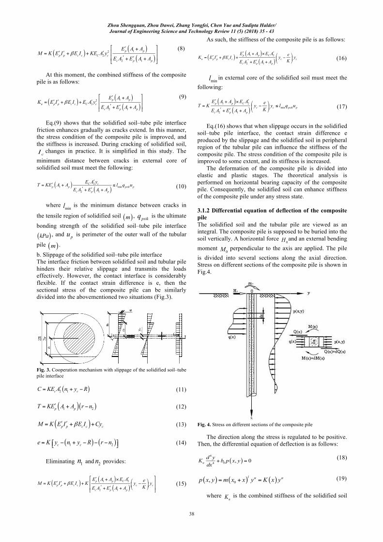
3.1.2 Differential equation of deflection of the composite pile The solidified soil and the tubular pile are viewed as an integral. The composite pile is supposed to be buried into the soil vertically. A horizontal force
0H and an external bending moment
0M perpendicular to the axis are applied. The pile is divided into several sections along the axial direction. Stress on different sections of the composite pile is shown in Fig.4.
Fig. 4. Stress on different sections of the composite pile
The direction along the stress is regulated to be positive. Then, the differential equation of deflection is as follows:
( )4
04 , 0ud yK b p x ydx
+ = (18)
( ) ( ) ( )0, l n np x y m x x y K x y= + = (19)
where
uK is the combined stiffness of the solidified soil
Zhou Shengquan, Zhou Dawei, Zhang Yongfei, Chen Yue and Sudipta Halder/ Journal of Engineering Science and Technology Review 11 (5) (2018) 35 - 43
39
pile and tubular pile; x and y are the horizontal displacement and buried depth of the composite pile; 0b is
the calculated width of the composite pile; m , l , and n are indexes that are going to be determined; ( )K x is the soil
stiffness at the pile side. This differential equation is applied to the composite pile
in the two stages.
3.2 Test on the horizontal bearing capacity of the composite pile 3.2.1 Experimental devices The pipe gallery project in Dongyangkou Port is in the Dayangkou, Rudong County, Nantong City, China. Single-pile horizontal bearing capacity was detected by performing a one-way cyclic loading test. In the test, loads was applied using an oil jack, and the counterforce was provided by neighbor piles. The devices used in the test included JCQ-503 static loading device, QW-100V jack, CYB-10 oil jack, and 0–50 mm dial indicator. The jack was placed transversely to apply the horizontal load. A spherical contact hinged support was set between the jack and the testing pile to assure that the acting line of force ran through the axial line of pile. Two dial indicators were installed symmetrically at two sides of the testing pile to measure its displacement under horizontal loads.
3.2.2 Test principle and method of horizontal bearing capacity Single-pile horizontal bearing capacity test is performed by measuring displacement of the ground pile at the acting point under different horizontal forces (one-way cyclic loading). In this manner, horizontal force-time-acting point ( )0H t Y− − relation curve and horizontal force–
displacement gradient ( )0H Y H−Δ Δ relation curve are
illustrated. Then, a contrast analysis on horizontal loading characteristics of tubular piles and composite piles is made. The one-way cyclic loading method is adopted according to Technical code for testing of building foundation piles (JGJ106-2014). In the test, loading process was accomplished in accordance with the staged manner of equivalent increment. The staged load shall be smaller than the 1/10 of the maximum test loads. After each staged loading, the load was kept constant by 4 minutes to measure the horizontal displacement and then unloaded to 0. The residual horizontal displacement was measured and read after pauses for 2 minutes. The above process was a one loading–unloading cycle. One loading staged test was accomplished after five cycles. Subsequently, the next staged test was implemented. In the whole test, loading with 10–15 stages was accomplished continuously. Loading stages to tubular pile and composite pile are listed in Table. 1.
4 Result Analysis and Discussion 4.1 Field test results In this section, three tubular and three composite piles were tested by using the one-way cyclic loading method. The diameter of tubular pile is Φ400 mm, and the composite pile is composed of solidified soil and tubular pile. The solidified
soil is the chemical churning pile with a diameter of Φ800 mm. The core pile is the tubular pile with a diameter of Φ400 mm. 7#, 12#, and 2# piles are tubular piles. 1#, 6#, and 3# are composite piles. Test curves of tubular piles and composite piles are shown in Figs.5 and 6.
(a)
Zhou Shengquan, Zhou Dawei, Zhang Yongfei, Chen Yue and Sudipta Halder/ Journal of Engineering Science and Technology Review 11 (5) (2018) 35 - 43
40
(b)
(c) Fig.5. Test curves of the tubular piles. (a) Test curves of 7# pile. (b) Test curves of 12# pile. (c) Test curves of 2# pile
The test curves of tubular piles are shown in Fig.5. Slopes of the 0H Y H−Δ Δ curve of tubular piles between the first and second characteristic points increases with the increasing loads. In accordance with the stress analysis of tubular pile under horizontal loads, the soil mass is approximately viewed in elastic state before the first
characteristic points. Subsequently, the soil mass is in the elastic–plastic stress state with the increasing horizontal load. Then, the soil mass fails when horizontal load reaches the second characteristic point. The stiffness of the tubular pile substantially decreases after the failure. Furthermore, the slope of the 0H Y H−Δ Δ curve increases dramatically.
(a)
Zhou Shengquan, Zhou Dawei, Zhang Yongfei, Chen Yue and Sudipta Halder/ Journal of Engineering Science and Technology Review 11 (5) (2018) 35 - 43
41
(b)
(c)
Fig. 6. Test curves of the composite pile. (a) Test curves of 1# pile. (b) Test curves of 6# pile. (c) Test curves of 3# pile
Fig.6 shows that the slope of the 0H Y H−Δ Δ curve of composite pile between the first and second characteristic points increases initially and then decreases with the increase of horizontal loads. Composite pile and soil mass are in the elastic state before the first characteristic point of the 0H Y H−Δ Δ curve. When the horizontal load approaches the first characteristic point, the tensile solidified soils in peripheral range of tubular piles develop toward the plastic state. Afterward, the plastic region extends, and cracks are developed with increasing loads. The stiffness of composite pile decreases, and the slope of the 0H Y H−Δ Δ curve increases. With the further increase of loads, cracks extend toward the tubular piles, and the slope of the
0H Y H−Δ Δ curve continues to increase. After cracks extend to the surface of tubular pile, crack extension is hindered. Furthermore, the bonding force on the interface between solidified soil and tubular pile is developed gradually, thereby increasing the stiffness of the composite pile. As a result, the slope of the 0H Y H−Δ Δ curve decreases with the increase of loads. When the horizontal load increases to the second characteristic point, the soil mass on the solidified soil–tube pile interface fails, and the slope of the 0H Y H−Δ Δ curve increases quickly. The tendency of the 0H Y H−Δ Δ curve of the composite pile further verifies the accuracy of the cooperation mechanism
of solidified soil and tubular pile in the composite pile. The comparison of composite piles 1#, 3#, and 6#
concludes that when the length–diameter ratio of the tubular pile is no less than 27.5, the single-pile horizontal bearing capacity in the composite pile is less affected with the continuous increase of the length–diameter ratio. Moreover, the horizontal displacement of composite piles with small length–diameter ratio (6#) is relatively small under the ultimate horizontal load.
The 0H Y H−Δ Δ curves of the composite piles and tubular piles have two characteristic points. The characteristic value of single-pile horizontal bearing capacity is equal to the horizontal load corresponding to the first characteristic point of the 0H Y H−Δ Δ curve. The ultimate value of single-pile horizontal bearing capacity is equal to the horizontal load corresponding to the second characteristic point of the 0H Y H−Δ Δ curve. The test results of horizontal static loads show that the characteristic value and ultimate value of single-pile horizontal bearing capacity in the composite piles are 1.81–2.62 and 2.00–2.25 times those of the tubular piles, respectively. Before the first characteristic point, the slope of the 0H Y H−Δ Δ curve of the composite pile is only approximately 1/6 of the tubular pile. Thus, the initial stiffness of the composite pile is much higher than that of the tubular pile. The single-pile horizontal bearing capacities of the tubular piles and the
Zhou Shengquan, Zhou Dawei, Zhang Yongfei, Chen Yue and Sudipta Halder/ Journal of Engineering Science and Technology Review 11 (5) (2018) 35 - 43
42
composite piles are listed in Table 2. Table 2. Horizontal bearing capacities of the tubular piles and the composite piles No.
Type of pile
No. of pile
Diameter of pile/mm
Length of
pile /m
Ultimate value of single-pile horizontal bearing
capacity /KN
Characteristic value of single-pile horizontal bearing capacity /KN
56 Tubular pile 400 16.0 5. Conclusion To study the bearing capacity of solidified soil–tube composite pile under horizontal loads, the formula of horizontal combined stiffness in the elastic and plastic stages was deduced theoretically. A one-way cyclic loading test was performed on six piles on site. The characteristic and ultimate values of horizontal bearing capacities for test piles was achieved through the horizontal force-time-acting point
0H t Y− − relation curve and the horizontal force–displacement gradient 0H Y H−Δ Δ relation curve. Some major conclusions can be drawn, as follows:
(1) Under the horizontal loads, the solidified soil in composite pile can increase the combined stiffness in the development from elastic to plastic deformation. In particular, solidified soil can remarkably enhance initial stiffness of the composite pile in the elastic stage.
(2) The horizontal force–displacement gradient curve of composite pile has two characteristic points. The composite pile is in the elastic state before the first characteristic point. However, it fails after the second characteristic point..
(3) The slope of the horizontal force–displacement gradient curve of composite pile between two characteristic points increases initially and then decreases with the increase of horizontal loads. Hence, when the composite pile is in the plastic stage, the plastic region is extended with increasing loads. Moreover, cracks are formed, thus decreasing the stiffness of piles. When cracks extend to the surface of tubular pile, the bonding force on the solidified soil–tube pile interface is developed gradually. This bonding force hinders crack extension and increases stiffness of the composite pile accordingly.
(4) The horizontal force–displacement gradient curve of
the composite pile is achieved on the basis of the field test. In accordance with the result of comparison between field test data and theoretical formula, the deduced formula of horizontal combined stiffness of the composite pile under elastic and plastic states is reasonable. Furthermore, it can be used to analyze the horizontal bearing capacity of the composite pile.
The bearing capacity of the solidified soil–tube composite pile under horizontal loads is investigated. This study focuses on the deduction of the formula of combined stiffness of the composite pile from elastic to plastic stages under the horizontal loads. Moreover, the deduced formula is accurately verified by combining one-way cyclic loading tests of tubular piles and composite piles. This study can provide references for the design and construction of composite piles. However, cI in the deduced equation changes in practice, because solidified soil cracks extend under the horizontal loads. It is simplified in the formula deduction process, where the composite pile is viewed as an ideal elastic plastic body. Further studies on potential creep deformation of composite pile are needed.
Acknowledgments This work was supported by the Major Universities Natural Science Research Project in Anhui Province (KJ2016SD19). This is an Open Access article distributed under the terms of the Creative Commons Attribution Licence
______________________________
References 1. Zhang, Y. C., Yang, G. H., Hu, H. Y., Chen, F. Q., Huang, Z. X.,
Chen, W. C., “Some problem about retaining structures for shallow pits in deep and soft areas of Pearl River Delta”. Chinese Journal of Geotechnical Engineering, 36(1), 2014, pp.1-11 (in Chinese).
2. Fook-Hou, Lee., Yeong, Lee., Chew, Soon-hoe., “Strength and modulus of marine clay-cement mixes”. Journal of Geotechnical and Geoenvironmental Engineering, 131(2), 2014, pp.178-186.
3. Ignat, R., Baker, S., Larsson, S., et al., “Two-and three-dimensional analyses of excavation support with rows of dry deep mixing columns”. Computers and Geotechnics, 66, 2015, pp.16-30.
4. Jamsawang, P., Voottipruex, P., Boathong, P., et al., “Three-dimensional numerical investigation on lateral movement and factor of safety of slopes stabilized with deep cement mixing column rows”. Engineering Geology, 188, 2015, pp.159-167.
5. Kitazume, M., Maruyama, K., “External stability of group column type deep mixing improved ground under embankment loading”. Soils and Foundations, 46(3), 2006, pp.323-340.
6. Kitazume, M., Maruyama, K., “Internal stability of group column type deep mixing improved ground under embankment loading”. Soils and Foundations, 47(3), 2006, pp.437-455.
7. Shi, F., Hao, S. L., “Field test for horizontal bearing capacity of PHC pipe piles”. Rock and Soil Mechanics, 36(2), 2015, pp.617-622(in Chinese).
8. Lin, H. J., “Research on Bearing Behaviors and Applications of Prestressed Concrete Uplift Pipe Piles”. Master thesis of Zhejiang University, China, 2010, pp.1-7.
9. Yang, Z. Q., “Research on the Engineering Property of Problem PHC Pile”. Master thesis of Zhejiang University, China, 2008, pp.5-9.
Zhou Shengquan, Zhou Dawei, Zhang Yongfei, Chen Yue and Sudipta Halder/ Journal of Engineering Science and Technology Review 11 (5) (2018) 35 - 43
43
10. Pitthaya, Jamsawang., Panich, Voottipruex., Pornkasem, Jongpradist., Dennes, T.Bergado., “Parameters affecting the lateral movements of compound deep cement mixing walls by numerical simulations and parametric analyses”. Acta Geotechnica, 10, 2015, pp.797-812.
11. Piti, Sukontasukkul., Pitthaya, Jamsawang., “Use of steel and polypropylene fibers to improve flexural performance of deep soil-cement column”. Construction and Building Materials, 29, 2012, pp.201-205.
12. Zheng, G., Diao, Y., Ng C W W, et al., “Parametric analysis of the effects of stress relief on the performance and capacity of piles in nondilative soils”. Canadian Geotechnical Journal, 48(8), 2011, pp.1354-1363.
13. Zheng, G., Peng, S. Y., Ng C W W, et al., “Excavation effects on pile behavior and capacity”. Canadian Geotechnical Journal, 49(12), 2012, pp.1347-1356.
14. Tang, M. X., Qi, Y. L., Zhou, Z. G., Hu, H. S., et al., “Study on experiment and theoretical calculation method of compressive bearing capacity of filled PHC pipe piles”. Building Structure, 45(1), 2015, pp.67-71 (in Chinese).
15. Thongmunee, S., Matsumoto, T., Kobayashi, S., et al., “Experimental and numerical studies on push-up load tests for sand plugs in a steel pipe pile”. Soils and Foundations, 51(5), 2011, pp.959-974.
16. Yongkyu, C., Michael, W. O., “Soil plugging and relaxation in pipe pile during earthquake motion”. Journal of Geotechnical and Geoenvironmental Engineering, 123(10), 1997, pp.975-982.
17. Wu, W. B., Jiang, G. S., Wang, K. H., Xie, B. H., Huang, S. G., “Influence of soil plug effect on vertical dynamic response of pipe piles”. Chinese Journal of Geotechnical Engineering, 36(6), 2014, pp.1129-1141 (in Chinese).
18. Wang, X. M., “Foundation Engineering”. Beijing: China Communications Press, China, 2010, pp.124-125.
19. Consoli, N C., Rasaa, D., Corte, M B, et al., “Porosity-cement ratio controlling strength of artificially cemented clays”. Journal of Materials in Civil Engineering, 23(8), 2011, pp.1249-1254.
20. Consoli, N C., Cruz, R C., Floss, M F., “Variables controlling strength of artificially cemented sand: influence of curing time”. Journal of Materials in Civil Engineering, 23(5), 2014, pp.692-696.
21. Consoli, N C., Cruz, R C., Fonseca, A V., et al., “Influence of cement-voids ratio on stress-dilatancy behavior of artificially cemented sand”. Journal of Geotechnical and Geoenvironmental Engineering, 138(1), 2012, pp.100-109.
22. Consoli, N C., Fonseca, A V., Silva, S R., et al., “Parameters controlling stiffness and strength of artificially cemented soils”. Geotechnique, 62(2), 2012, pp.177-183.
23. Deng, Y. F., Wu, Z. L., Liu, S. Y., Yue, X. B., Zhu, L. L., Chen, J. H., Guan, Y. F., “Influence of geopolymer on strength of cement-stabilized soils and its mechanism”. Chinese Journal of Geotechnical Engineering, 38(3), 2016, pp.446-453 (in Chinese).
24. Wu, M., Hou, W. M., Wang, E. Y., “Discussion on depth modification of cohesive pile composite foundation bearing capacity”. Industrial Construction, 44(11), 2014, pp.123-125 (in Chinese).
25. Panich, Voottipruex., Taweephong, Suksawat., D.T.Bergado., Pitthaya, Jamsawang., “Numerical simulations and parametric study of SDCM and DCM piles under full scale axial and lateral loads”. Computers and Geotechnics, 38, 2011, pp.318-329.
26.Pitthaya, Jamsawang., Naphol, Yoobanpot., Nuttawut, Thanasisathit., Panich, Voottipruex., Pornkasem, Jongpradist., “Three-dimensional numerical analysis of a DCM column-supported highway embankment”. Computers and Geotechnics, 72, 2016, pp.42-56.