59
Study Unit External I/O Devices and Printers Reviewed By Brandon Nolta
| Date post: | 05-Dec-2015 |
| Category: |
Documents |
| Upload: | ileana-craita |
| View: | 225 times |
| Download: | 2 times |

Study Unit
External I/O Devicesand PrintersReviewed By
Brandon Nolta

About the Reviewer
Brandon Nolta has more than a decade of experience in information
technology, system administration, software testing, technical
documentation, and freelance writing. He has worked for several
companies in various technical capacities, including Hewlett-Packard
and MPC. His freelance experience includes working as an Internet
researcher for the Sci-Fi Channel (now SyFy).
Mr. Nolta has a bachelor’s degree in mathematics from the
University of Idaho and a master’s degree in English from Boise
State University. He holds several technology-related certifications,
including A+, Network+, and Microsoft Certified System Adminis-
trator (MCSA).
Copyright © 2011 by Penn Foster, Inc.
All rights reserved. No part of the material protected by this copyright may bereproduced or utilized in any form or by any means, electronic or mechanical,including photocopying, recording, or by any information storage and retrieval system, without permission in writing from the copyright owner.
Requests for permission to make copies of any part of the work should be mailed to Copyright Permissions, Penn Foster, 925 Oak Street, Scranton,Pennsylvania 18515.
Printed in the United States of America
All terms mentioned in this text that are known to be trademarks or service marks have been appropriately capitalized. Use of a term in this text should not beregarded as affecting the validity of any trademark or service mark.

The personal computer (PC) that you’ve been working with
consists of more than just a system board and some expan-
sion cards contained in the system case. You should think of
the PC as a “system” that incorporates many different types
of components and devices with different functions. As a PC
repair technician, you’ll be called upon to support entire PC
systems including monitors, keyboards, and printers.
This study unit identifies and describes the typical I/O
(input/output) devices you’ll encounter in supporting a
computer system. It also discusses the interconnections
required to connect I/O devices to your PC and explains how
the operating system communicates with these devices.
iii
Previe
wPrevie
w
When you complete this study unit, you’ll beable to
• Describe the system resources used to supportinput/output devices
• Install a new device on a personal computer
• Resolve resource conflicts
• Describe the cabling and connection options whenadding a new device
• Identify and evaluate I/O devices
• Explain how printers work
• Support, troubleshoot, and repair printers
• Install a printer on a PC or on a local area network(LAN)
Remember to regularly check “My Courses” on your student homepage.
Your instructor may post additional resources that you can access to
enhance your learning experience.

ATTACHING I/O DEVICES 1Fundamentals of Peripheral Installations 1Embedded BIOS on Devices 2Device Drivers 2Application Software 5Ports and Expansion Slots 5Using PCI Expansion Slots 6When Device Installations Create Problems 8Using Serial Ports 8Using Parallel Ports 10SCSI Devices 10Using USB Ports 12Using FireWire/iLink Ports 14
EXTERNAL I/O DEVICES 17Keyboards 17Pointing Devices 17Monitors 20Video Cards 22Modems 24Installing Devices Using Windows 7 25Plug-and-Play Devices 27Hot-Pluggable Devices 29USB Devices 29Other Add-on Devices 34
PRINTERS 42Laser Printers 42Color Laser Printers 44Color Ink-Jet Printers 46Color Management 47Sharing Printers 50Products for Network Printers 51Practical Exercise 51
SELF-CHECK ANSWERS 55
v
Contents
Contents

1
ATTACHING I/O DEVICESVarious system resources are needed to install and support
external devices. In the following sections, we’ll explain how
the operating system communicates with devices. You’ll learn
how to install a new device on a PC and how to resolve con-
flicts that are caused when two devices request the same
system resources. In addition to the standard legacy system
ports, you’ll also learn about USB and FireWire/iLink ports,
which allow a variety of devices to be easily connected to
your PC.
Fundamentals of PeripheralInstallationsAdded peripherals need a device driver or BIOS system
resources, which may include an interrupt request number
(IRQ), direct memory access channel (DMA channel), input/
output addresses (I/O addresses), upper memory addresses,
and application software.
Software has many different levels, including device drivers
that interface with the hardware and application software
that interfaces with the drivers.
When several peripheral devices are added to a system, they
might try to use the same resources, which could cause
peripherals not to work. When two devices try to use the
same IRQ, DMA channel, I/O address, or upper memory
addresses, it usually causes problems.
External I/O Devices and Printers

External I/O Devices and Printers2
Some peripherals are internal, meaning that they’re installed
inside the computer case. Internal peripherals include optical
drives and Zip drives, along with cards to support audio,
video, and communications. External peripherals include
printers, plotters, scanners, projectors, cameras, building
environmental controls, lighting, security systems, and a host
of others.
There are three basic steps for adding peripherals to a PC: (1)
plug in the device, (2) install drivers, and (3) install application
software.
Embedded BIOS on DevicesSome peripheral devices require several levels of software.
Some external devices store needed software in their own
cabinet, on a ROM chip, or a ROM chip on the interface board.
This is called firmware or BIOS. Some peripheral devices
designed for use on a wide variety of systems contain RAM for
temporary storage of data. The technique varies with devices
and can include flipping DIP switches, moving jumpers, and
in most cases, using programs provided by the device manu-
facturer. Rarely, it’s necessary during installation to interface
with the BIOS to set an IRQ number or I/O addresses.
In some cases, system BIOS as well as device BIOS may
come into play. BIOS on the hard drive manages access to
the hard drive, while system BIOS on the system board man-
ages communication between the hard-drive BIOS and the
operating system (OS).
Device DriversPeripherals require device drivers. The two common types
of drivers since Windows Vista was released are 32-bit and
64-bit. Windows uses 32-bit drivers natively, unless you’re
using a 64-bit version of Windows.

External I/O Devices and Printers 3
Windows 32-Bit and 64-Bit Drivers
Unlike previous versions, Windows XP and later doesn’t need
to load drivers in specific startup files, because all common
drivers are preloaded in the operating system. Booting the
system with the device plugged in tells Windows to activate
the driver. Windows drivers can be activated when a device is
used and deactivated when not used to conserve memory.
Most extra Windows drivers come as part of a hardware
package on a CD when you purchase a device. Windows and
some device manufacturers offer the latest revisions to drivers
on their Web sites. Windows allows you to view and change
device drivers from the Control Panel. In Windows 7, for
example, click on Start, then Control Panel. Then click on
Display and click Adjust Resolution to view the currently
installed display driver, as shown in Figure 1.
To change the driver, click on Advanced Settings, the
Adapter tab, the Properties button, the Driver tab, and then
the Update Driver button. The Update Device Driver Wizard
will appear, as shown in Figure 2.
You can search manually for supported drivers or let Windows
search for you. If you have a driver from a device that’s not
supported by Windows, perform the search manually by
FIGURE 1—CurrentlyInstalled Display Driver

External I/O Devices and Printers4
selecting Browse my computer for driver software. Click
Let me pick from a list to be able to add the driver from a
CD, DVD, or a downloaded folder on the hard drive, as
shown in Figures 3 and 4.
FIGURE 2—UpdateDevice Driver WizardDialog Box
FIGURE 3—Update DeviceDriver Wizard Installation

External I/O Devices and Printers 5
Always use 32-bit drivers with 32-bit Windows systems and
64-bit drivers with 64-bit Windows systems. While 64-bit
Windows versions can use 32-bit drivers, performance will
decrease.
Application SoftwareMost devices include basic application software so they can
be used as soon as they’re installed. For example, a scanner
will usually include software to scan and manipulate images
and documents. Advanced application software can be pur-
chased to replace the basic software included with the device
and provide more function.
Ports and Expansion SlotsThere are several ways that devices can connect to a PC. The
following is a preview of the topics we’ll discuss for connect-
ing devices to your computer.
Most computers come with serial, parallel, USB, and some-
times FireWire/iLink ports mounted on the system board. On
older systems, an I/O controller card in an expansion slot
provided serial and parallel ports.
FIGURE 4—Choose thedriver you want to use.

External I/O Devices and Printers6
Using PCI Expansion SlotsPCI and PCI-Express are local buses that run in sync with
the CPU. PCI-Express slots are often colored yellow so they
can be easily distinguished from the PCI expansion slots,
which are usually white or green. Figure 5 shows the PCI-
Express X16 and X1 slots on a system board for comparison.
Because the PCI-Express bus is faster than the PCI bus, PCI-
Express slots are often used for fast I/O devices such as
network cards or graphics adapters. When installing either a
PCI or PCI-Express card, it’s unlikely you’ll need to configure
the IRQ or I/O address because the startup PnP BIOS and
onboard bus controller do this for you.
Use the Device Manager to see which IRQ has been assigned
to a PCI device. Go to Settings and click on Control Panel.
Click on the System icon to bring up the System Properties
window. Select the Device Manager link. Now, suppose your
PC has a PCI video card. Clicking the c next to “Display
adapters” will yield the name of this video card. Double-click
on the device to bring up its Resources window; here you can
find which IRQ (09, 10, 11) has been assigned to the device.
PCI-Express Slots PCI (Peripheral Component Interface) and PCI-Express expansion slots on
the system board allow insertion of expansion cards to attach devices to
the PCI and PCI-Express buses.
Serial Port A male communication port on a computer used for transmitting data seri-
ally, one bit at a time. Serial ports are often called COM1, COM2, COM3,
etc., and use DB-9 or DB-25 connectors.
Parallel port A female communication port on a computer used for transmitting data in
parallel, eight bits at a time. Ports are labeled LPT1 and LPT2.
SCSI SCSI (usually pronounced scuzzy) stands for “Small Computer System
Interface.” SCSI adapters can have many different standards that need to
be taken into consideration when matching the host adapter and the con-
nected devices.
USB The Universal Serial Bus is standard on newer computers. It attaches a
wide range of devices and is easier to use than serial and parallel ports.
FireWire/iLink A high-speed serial bus often used to connect real-time data devices such
as audio/visual equipment to a PC. Also known as IEEE 1394 (Institute of
Electrical and Electronic Engineers).

External I/O Devices and Printers 7
PCI Bus IRQ Steering
Starting with PCI 2.1, PCI and PCI-Express both utilize PCI
bus IRQ steering, making it possible for PCI devices to share
an IRQ. By using PCI bus IRQ steering, Windows can auto-
matically assign or “steer” the PCI bus’ IRQs. All versions of
Windows from XP forward support IRQ steering.
Sometimes an IRQ conflict can happen when the startup
BIOS isn’t aware that a legacy device is using a particular
IRQ and assigns that IRQ to the PCI or PCI-Express bus,
which then assigns it to a specific device. With IRQ steering,
Windows can sometimes solve the problem by reassigning
another IRQ to the bus to allow the legacy device to be the
sole owner of its IRQ.
For this to happen, Windows must detect an unused IRQ and
assign it as a substitution. It then reserves this IRQ for PCI
or PCI-Express use. The word “Holder” indicates an IRQ is
reserved.
IRQ steering can also cause a problem. If Windows puts a
holder on an IRQ, this might cause the device using it to
have problems. Also, if two devices are having conflicts,
CaseBack
CaseFront
PCI–Express x16
PCI–Express x1
AGP
PCI
FIGURE 5—PCI-ExpressSlots

External I/O Devices and Printers8
sometimes IRQ steering can mask the problem, making it dif-
ficult to diagnose. IRQ steering can erroneously put a holder
on an IRQ that’s being used by a legacy device.
When Device Installations Create ProblemsSuppose you install a new sound card and it doesn’t work.
You also notice your network card has stopped communicat-
ing. Poor cable or card connections can cause these symptoms.
Check all connections, then remove the sound card and see if
the network card starts working again.
Device documentation is the best place to begin diagnosing
device installation problems.
Using Serial PortsSerial ports are always male ports on the computer and use
DB-9 or DB-25 connectors. DB stands for data bus, and the
number 9 or 25 indicates the number of pins (Figure 6).
25–Pin Female Parallel Port
9–Pin Male Serial Port 15–Pin Female Game Port
FIGURE 6—Serial, Parallel, and Game Ports

External I/O Devices and Printers 9
Designers designated COM1, COM2, COM3, and COM4 as
serial ports to simplify allocation of system resources. COM
assignments represent a designated IRQ and I/O address, as
shown in Table 1.
Serial ports are physical connections. COM assignments are
logical connections. Saying COM1 is the same thing as saying
IRQ4 and I/O address 03F8.
Configuring an I/O card with a serial port COM assignment
usually requires the arrangement of jumpers on the card.
CMOS is most often used for COM assignments of ports con-
nected directly to the system board. Sometimes the setup
screen shows COM assignments, and sometimes it shows the
IRQ and I/O address.
A serial port conforms to the standard interface called
RS-232 (Reference Standard 232). Sometimes written
RS-232b or RS-232c, the lower-case “b” or “c” represents
the revision level. Even though serial ports are available in 9-
and 25-pin configurations, only nine of the pins are used.
Adapters are available on the market to convert the ports to
suit whatever serial cables you happen to be using.
Table 2
STANDARD DEFAULT PORT ASSIGNMENTS
Port IRQ I/O Address in Hex Type
COM1 IRQ4 03F8-03FF Serial
COM2 IRQ3 02F8-02FF Serial
COM3 IRQ4 03E8-03EF Serial
COM4 IRQ3 02E8-02EF Serial
LPT1 IRQ7 0378-037F Parallel
LPT2 IRQ5 0278-027F Parallel
1

External I/O Devices and Printers10
Using Parallel PortsTypically, there are three types of printer ports:
• SPP—Standard parallel port
• EPP—Enhanced parallel port
• ECP—Extended-capabilities parallel port
The SPP is often referred to as a Centronics port or normal
parallel port. The name “Centronics” is taken from the 36-pin
connection used for printers (Figure 7). A standard parallel
port allows data flow in only one direction.
The EPP and ECP are both bidirectional.
The extended-capabilities parallel port
uses Direct Memory Access (DMA).
Cable length can be critical in parallel port
connections. Ten feet is normally satisfac-
tory, but you should never exceed fifteen
feet.
When configuring parallel ports it’s impor-
tant to read the documentation provided
with the I/O card. If the port is connected
directly to the system board, look at CMOS
setup to configure the port.
SCSI DevicesInstalling a SCSI device is normally done one of two ways:
1. Install the SCSI device using a simplified version of a
SCSI host adapter designed to accommodate one or two
devices. These adapters often come bundled in the SCSI
device package.
2. Install the SCSI device on an existing or new host
adapter designed to handle several devices.
DB 25–PinConnection
36–PinCentronicsConnection
(Printer)
FIGURE 7—Standard Parallel Printer Cable

External I/O Devices and Printers 11
Matching the Host Adapter to SCSI Devices
When matching a host adapter or determining if an existing
host adapter will work with a new SCSI device, consider the
following:
• Legacy SCSI standards include SCSI-1, SCSI-2, SCSI-3,
and Fast SCSI. Current SCSI standards include Wide
Ultra 2 SCSI, Ultra 160 SCSI, Ultra 320 SCSI, and Ultra
640 SCSI.
• SCSI-1, SCSI-2, and Fast SCSI use 50-pin connectors.
• Wide SCSIs use 68-pin connectors, while Ultra SCSIs
use 68- or 80-pin connectors.
A SCSI device must match the host adapter based on the
number of pins on the connectors and compatibility stan-
dards between the host adapter and the device.
The host adapter must fit the expansion slot you plan to use.
SCSI host adapters come in either PCI or PCI-Express bus.
For faster data transfer rate, it’s better to use the PCI-Express
bus.
Choose a host adapter that uses bus mastering. Buses that
support bus mastering don’t require a DMA channel for the
SCSI host adapter.
Host adapters are available that allow you use 50-pin and
68-pin connectors along with several standards that allow
you to choose a variety of devices without the need for a
second adapter. Select a host adapter that supports one of
the leading driver standards: Advanced SCSI Programming
Interface (ASPI) or Common Access Method (CAM). Be sure
the host adapter and all device drivers meet the same stan-
dard (Figure 8).
The ASPI or CAM standard also affects the way the host
adapter relates to the OS. Many host adapters provide their
own host adapter drivers to be used by the OS. Manufacturers
of host adapters usually provide the drivers on a CD-ROM.
Select a host adapter that matches the device according to its
electronic signaling method. The cable choices are single-
ended and differential. Don’t mix the two, or you could
damage the devices.
Bus mastering is a feature supported bysome bus architecturesthat enables a controllerconnected to the bus tocommunicate directlywith other devices onthe bus without goingthrough the CPU. Mostmodern bus architec-tures, including PCI,support bus masteringbecause it improvesperformance.

External I/O Devices and Printers12
Using USB PortsUsing Universal Serial Bus (USB) ports is less
complicated than using parallel or serial
ports. The OS, together with the USB host
controller, manages the USB port resources.
Like the SCSI bus we just discussed, all
ports and devices on the universal serial
bus use only one IRQ, I/O address, and
DMA channel (Figure 9).
Most system boards have two or more USB
ports. Expansion cards with USB ports are
available for older systems. To install a USB
device you’ll need
• A USB port or expansion card with USB
port and USB firmware
• A USB device driver
Operating System
SCSI Host Adapter
ASPI Standard
ASPI Standard
ASPI StandardASPI Standard ASPI Standard
SCSIDevice Driver 2
SCSIDevice 2
SCSIDevice Driver 3
SCSIDevice 3
SCSIDevice Driver 1
SCSIDevice 1
FIGURE 8—The SCSIdevice driver standardaffects the interaction of the host adapter with thedevice.
One Setof System
ResourcesUsed Here
USB HostController
HandlesMultipleDevices
Operating System(Windows 7)
USB Device Driver
Firmware on SystemBoard Contains theUSB Host Controller
(Bus Master)
USB Firmwareon Device
USB Device FIGURE 9—Only one IRQ, I/O address, and DMAchannel are needed for a USB host controller tomanage multiple devices.

External I/O Devices and Printers 13
Use the following general steps to install a USB device.
1. Using the Device Manager, verify that the USB host con-
troller driver is installed (Figure 10). If the controller isn’t
installed, install it from the Control Panel by double-
clicking the Devices and Printers icon. If you have
trouble installing the controller, verify that support for
USB is enabled.
2. Plug in the USB device and install its device driver.
For example, if installing a scanner, insert the CD that
came with the scanner in the optical drive and enter
D:\Setup.exe in the Run dialog box. Follow the screen
prompts, if any, to complete installation. Verify that
Windows sees the device in the Device Manager with no
conflicts and without errors.
3. Install the application software to use the device. Conduct
a test operation of the device to confirm that everything
is functioning properly.
FIGURE 10—Using DeviceManager, verify that theUSB host controller isinstalled.
External I/O Devices and Printers14
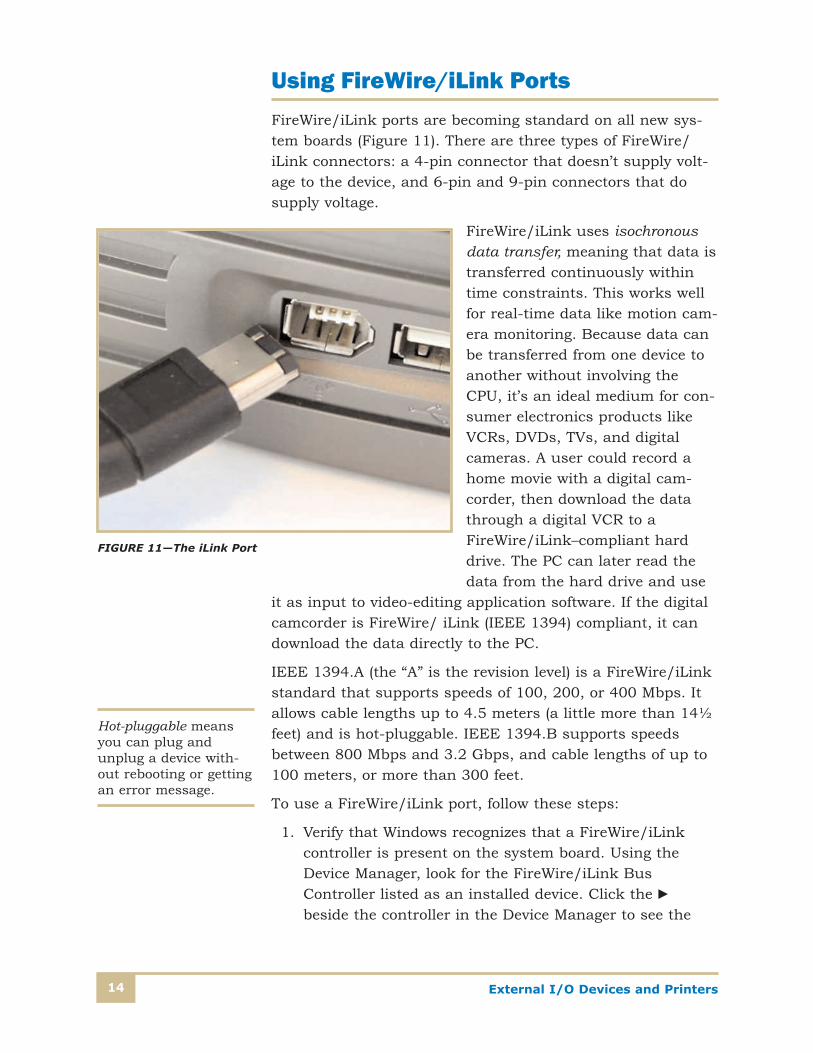
Using FireWire/iLink PortsFireWire/iLink ports are becoming standard on all new sys-
tem boards (Figure 11). There are three types of FireWire/
iLink connectors: a 4-pin connector that doesn’t supply volt-
age to the device, and 6-pin and 9-pin connectors that do
supply voltage.
FireWire/iLink uses isochronous
data transfer, meaning that data is
transferred continuously within
time constraints. This works well
for real-time data like motion cam-
era monitoring. Because data can
be transferred from one device to
another without involving the
CPU, it’s an ideal medium for con-
sumer electronics products like
VCRs, DVDs, TVs, and digital
cameras. A user could record a
home movie with a digital cam-
corder, then download the data
through a digital VCR to a
FireWire/iLink–compliant hard
drive. The PC can later read the
data from the hard drive and use
it as input to video-editing application software. If the digital
camcorder is FireWire/ iLink (IEEE 1394) compliant, it can
download the data directly to the PC.
IEEE 1394.A (the “A” is the revision level) is a FireWire/iLink
standard that supports speeds of 100, 200, or 400 Mbps. It
allows cable lengths up to 4.5 meters (a little more than 14½
feet) and is hot-pluggable. IEEE 1394.B supports speeds
between 800 Mbps and 3.2 Gbps, and cable lengths of up to
100 meters, or more than 300 feet.
To use a FireWire/iLink port, follow these steps:
1. Verify that Windows recognizes that a FireWire/iLink
controller is present on the system board. Using the
Device Manager, look for the FireWire/iLink Bus
Controller listed as an installed device. Click the c
beside the controller in the Device Manager to see the
FIGURE 11—The iLink Port
Hot-pluggable meansyou can plug andunplug a device with-out rebooting or gettingan error message.

External I/O Devices and Printers 15
specific brand of FireWire/iLink controller the board con-
tains. If the controller isn’t installed or isn’t working,
reinstall the driver. In the Control Panel window, double-
click the Devices and Printers icon. If you have problems
installing the driver, verify that FireWire/iLink support is
enabled.
2. Plug the device into the FireWire/iLink port. Install the
device driver for the device. For example, for a Sony
camcorder, insert the CD that contains the supporting
software into the optical drive and follow the AutoPlay
prompts to install the software. If the disc doesn’t auto-
start, click Start and type <drive>:\Setup.exe in the
Search programs and files field, where <drive> is the
drive letter of your optical drive. When the device is
plugged in and the drivers are installed, you should see
the device listed in the Device Manager under Sound,
Video and Game Controllers. If you don’t see it, turn the
camcorder off and then back on.
3. Install the application software to use the device. Conduct
a test operation of the device to confirm everything is
functioning properly.
For system boards that don’t support FireWire/iLink, you can
install a FireWire/iLink host adapter.

External I/O Devices and Printers16
Self-Check 1
At the end of each section of External I/O Devices and Printers, you’ll be asked to pause
and check your understanding of what you’ve just read by completing a “Self-Check”
exercise. Answering these questions will help you review what you’ve studied so far.
Please complete Self-Check 1 now.
1. What are the two types of expansion slots usually found on the system board?
__________________________________________________________
__________________________________________________________
2. Serial and parallel ports were provided on older systems by a(an) _______.
3. True or False? A port designated as COM1 is a parallel port.
4. What type of device connection uses 68-pin and 80-pin connectors?
__________________________________________________________
__________________________________________________________
5. Explain the difference between the SPP and EPP types of parallel ports.
__________________________________________________________
__________________________________________________________
Check your answers with those on page 55.

External I/O Devices and Printers 17
EXTERNAL I/O DEVICESNow that we’ve covered the various means that the PC pro-
vides to attach devices, let’s look at some of the I/O devices
themselves. Here, we’ll discuss some of the features of I/O
devices and identify the different ways they can attach to the PC.
KeyboardsKeyboards connect to a PC by one of three methods: (1) the
PS/2 (Personal System 2) connector, (2) a USB port, or (3) a
wireless transmitter (Figure 12). Although USB connectors
are hot-pluggable, as a precaution it’s best to consider all
keyboards not hot pluggable. We’ll discuss USB keyboards
later in this section of your study unit.
Pointing DevicesThe most common pointing device is the mouse—more specif-
ically, the wheel mouse or the optical mouse. A wheel mouse
contains a ball, as shown in Figure 13, that moves as it’s
dragged across a surface. Wheels with small holes in them
are turned by the ball’s motion. An optical light sensor looks
6–Pin DIN PS–2Connector Ports(Mini–DINS)
(A) (B)
FIGURE 12—System boards contain ports for the USB or 6-pin PS/2 connector.

External I/O Devices and Printers18
through the small holes in the wheels and sends pulses to
the CPU. The X-axis tracks horizontal mouse movement and
the Y-axis tracks vertical mouse movement.
An optical mouse contains a small camera and microchip
(Figure 14). The camera looks through a very small hole at
the work surface up to 1,500 times a second and sends sig-
nals to the CPU via the microchip.
A mouse can have two or three buttons. Software must be
programmed to use these buttons. Nearly all applications use
the left button. Use of the center and right buttons depend
on the operating system and application software. Most mice
also have a scroll wheel between the buttons.
A mouse can be connected to a computer by using
• A dedicated round mouse port directly on the system
board (the mouse is then called a system board mouse or
PS/2 compatible mouse)
• A USB port
Rubber Ball
“Chopper” Wheelfor Y–Axis
“Chopper” Wheelfor X–Axis
X Output
LightDetector
LightDetector
LightSource Light
SourceRoller forX–Axis
Roller forY–Axis
Y Output
FIGURE 13—Inside a Wheel Mouse

External I/O Devices and Printers 19
• A Y connection with the keyboard so that both the
keyboard and mouse share the same port
• A wireless transmitter
The advantages and disadvantages of each connection type
are based on the resources they require. A system board
mouse is the first choice for most users because the port on
the system board doesn’t take any resources that other devices
might need. If your system board port becomes damaged, you
can switch to a USB port or wireless connection.
To clean a mouse or tracker ball, remove the mouse cover
from the bottom. A few puffs of canned air are normally all
that’s needed. On a mouse that’s especially dirty, use 99%
isopropyl alcohol to clean the wheels and surfaces of the
photo sensors. Warm soapy water is best for cleaning the
ball. Keep alcohol away from the ball because it can dry the
rubber coating.
TinyCameraHole
FIGURE 14—OpticalMouse

External I/O Devices and Printers20
MonitorsMonitors are often rated by screen size, resolution, and
refresh rate. Desktop computers typically used cathode ray
tube (CRT) monitors until the early 2000s, when flat-panel
liquid crystal displays (LCDs) began to gain popularity. Note-
book computers use LCDs.
Screen size. Common screen sizes are 15-inch, 17-inch,
19-inch, 21-inch, and 23-inch. When matching a monitor to
a video card, a good rule of thumb is to use a midrange video
card for a mid-sized monitor and a high-end video card for a
large monitor.
Refresh rate. Slow refresh rates make the image appear to
flicker while faster refresh rates make the image appear more
solid and stable.
Resolution. The resolution depends on the video controller
card and software to use the capabilities of the monitor. The
standard resolution for most software is 800 � 600 pixels,
even though monitors are rated on the average of 1024 � 768
pixels. Resolution is set in Windows from the Control Panel
and requires a driver capable of that resolution. High resolu-
tion usually requires more video RAM.
Green monitors. These monitors comply with EPA Energy
Star standards. Requirements for Energy Star certification
vary based on the monitor’s capabilities, but in general, an
Energy Star–certified LCD monitor uses less than 2 watts in
sleep mode and, for most consumer models, less than 100
watts in active mode.
ELF emissions. “ELF” stands for extremely low frequency
(3–30 Hz; 100,000–10,000 km). Most computer monitors
today comply with at the least the minimum industry stan-
dards for ELF emissions.
Flat-panel monitors replaced CRT monitors because they
take up less space, weigh less, use less electricity, and have a
clearer image than CRT monitors (Figure 15). LCD flat-panel
monitors are available in two major types: active matrix and
dual-scan passive matrix. Dual-scan passive matrix is less
expensive and doesn’t have as sharp an image as active
matrix. With dual-scan, two column electrodes are activated

External I/O Devices and Printers 21
at the same time. In active matrix, an added transistor ampli-
fies the signal at each pixel, enhancing the image.
An LCD panel produces an image using a layered grid of elec-
trodes, a color layer, and a liquid crystal layer. One grid of
electrodes accesses rows while the other accesses columns.
Each intersection of a row and a column electrode form one
pixel on the panel. When electricity is applied to a pixel, it
becomes clear and allows light to pass through, illuminating
(or picking up) color from the color layer.
Flat-panel monitors for desktop PCs are designed to receive
either digital or analog signals from the video card and have
two ports to accommodate either. If the signal is analog, it’s
converted to digital so that the monitor can display it. Video
cards connect digital data from the CPU to analog data. This
data is reconverted back to digital by the monitor. This back-
and-forth conversion decreases image quality. For best
performance, use a digital video card designed for LCDs
when installing an LCD flat-panel monitor.
FIGURE 15—Being much less bulky than the CRT monitor, theflat-panel monitor takes up less space and weighs less as well.

External I/O Devices and Printers22
Video CardsVideo cards are known by many names, including
• Graphic adapters
• Video boards
• Graphics cards
• Display cards
The main features to look for in a video card are the bus it
uses and the amount of video RAM it has or can support.
How a Video Card Works
One of the main functions of a video card is to convert digital
signals to analog so a CRT monitor can use them. A RAM
DAC chip on the video card normally does the conversion.
RAM DAC contains three digital-to-analog converters, one for
each of the CRT monitor’s three color guns: red, green, and
blue.
Figure 16 illustrates the four basic functions of a video card:
1. Receiving digital data from the system bus
2. Writing the digital data to video memory
3. Passing the data from video memory to the digital analog
converter (RAM DAC), where it’s converted to analog data
4. Channeling the analog data from RAM DAC to the
monitor
RAM DAC stands for“random access memory digital-to-analog converter.”
RGB VideoPort to Monitor
Video RAM
Video Card
Video Chip Set
PCI Bus Connector
Digital Data
Analog Data
Digital Data
RAM–DAC
FIGURE 16—BasicFunctions of a VideoCard

External I/O Devices and Printers 23
The Bus Used by the Video Card
The speed and performance of a video card are partially a
function of the bus the card is using. In 1995, video cards
were designed to use the PCI bus. Newer cards use the PCI-
Express bus. Older cards were designed to operate on VESA
local buses (VL-bus), a proprietary local bus, ISA buses, AGP
buses, and EISA buses. Except for PCI and PCI-Express,
these bus types are all obsolete; hardware using the AGP bus
is still available, but has become far less common since PCI-
Express was introduced in 2003.
The fastest bus for video today is PCI-Express. The standard
PCI-Express slot has between 36 and 142 pins, depending on
the number of buses the card has. The chipset, memory, and
RAM DAC on the card determine performance. One method
to improve performance is to allow both the video chipset and
the RAM DAC (input and output) to access video memory at
the same time. This is called dual porting.
The bus external to the video card is the PCI or PCI-Express
bus, but the card itself also has an internal video bus. The
volume of data that can travel on a bus is called bandwidth.
Current video buses use a data path that can be 32 bits, 64
bits, 128 bits, or 256 bits wide. Effective bandwidth of the
card is partially determined by the width of the data path
and the memory on the card.
Graphics Accelerators
A graphics accelerator is a type of video card that has its own
processor. Today’s high demand for fast, high-quality graphics
has made graphics accelerators a necessity.
Processors on graphics accelerator cards are similar to a CPU
but designed to manage video and graphics. Some graphics
accelerator card features include MPEG decoding, 3-D graph-
ics, dual porting, color space conversion, interpolated scaling,
EPA green-PC support, and digital output to LCD monitors.
Graphics accelerator cards speed up the process and reduce
the burden on the system board CPU.

External I/O Devices and Printers24
Video Memory
The amount of data received by a video card from the CPU for
each frame (or screen) of data is determined by the screen
resolution (or pixels), number of colors (or color depth meas-
ured in bits), and enhancements to color information called
alpha blending (Table 2). The more data used to create a
single screen, the more memory is needed in the frame buffer
to hold that data. In addition to the frame buffer, the video
card may have other needs for memory, such as for fonts and
custom logos.
Color depth is directly related to the number of bits used to
compose one pixel and can be 4, 8, 16, or 24 bits per pixel.
The larger the number of bits allocated to storing each piece
of data, the greater the number of color shades (color depth)
you have.
ModemsModems are hardware devices that connect computers
together either through phone lines or direct wiring with each
other. When computers are connected together, they form a
Table 2
VIDEO RAM REQUIRED FOR DIFFERENT VIDEO RESOLUTIONS AND COLOR DEPTHS
VideoResolution
4-Bit ColorDepth (16Colors)
8-Bit ColorDepth(256Colors)
16-Bit ColorDepth(65,000Colors)
24-Bit TrueColor (16.7MillionColors)
32-Bit/24-Bit TrueColor with8-Bit AlphaChannel
800 ✕ 600 512 K 512 K 1 MB 2 MB 2 MB
1,024 ✕ 768 1 MB 1 MB 2 MB 4 MB 4 MB
1,152 ✕ 1,024 1 MB 2 MB 2 MB 4 MB 4 MB
1,280 ✕ 1,024 1 MB 2 MB 4 MB 4 MB 6 MB
1,600 ✕ 1,200 2 MB 2 MB 4 MB 6 MB 8 MB

External I/O Devices and Printers 25
network. There are many different types of modems and net-
works, but most modems today are broadband, meaning
high-speed Internet, as opposed to dial-up modems. Internal
modems are expansion cards typically having two RJ-11
phone line connectors. External modems have their own case
and power supply and usually connect to the computer
through a USB or IEEE 1394 port. External modems also
have RJ-11 phone line connectors to connect with other
modems.
Installing Devices Using Windows 7Now we’re going to cover installation options using Windows 7.
Specifically, we’re going to concentrate on the Device Manager
and Properties screens for new devices. We’ll also focus on the
use of PnP and hot-pluggable devices.
To display the Device Manager screen, select Start, Control
Panel, and System; then click Device Manager (Figure 17).
RJ-11 is an abbrevia-tion for “registered jackfunction 11.” Thisdevice has a two-wiredial tone on a four-pintelephone jack.
FIGURE 17—Opening the Device Manager in Windows 7

External I/O Devices and Printers26
You’ll need the administrator level of system security privi-
leges to make any changes using the Device Manager. Make
sure you have this level of clearance from your company’s
system administrator (if it’s a business situation) before you
attempt to access the Device Manager. If you’re a single or
home user, log on using the administrator level of sign-on.
On the Device Manager screen the same options are avail-
able as in other Windows operating systems, but again, in
Windows 7, the options look different. To find the IRQ assign-
ments on your system, select the View pull-down and then
click on Resources by type (Figure 18). Click the arrow next
to Interrupt request. You won’t need to change or even know
these settings, as Windows handles them automatically, but
it can be helpful to know where to find them.
If conflicts are discovered after installing a device, Windows 7
may create a “Conflicting device list.” To get this list and have
the option to correct it, go to Device Manager, right-click on
FIGURE 18—Finding the Resource Assignments Using Windows 7

External I/O Devices and Printers 27
the device, and select Properties (Figure 19). On the Properties
screen, you’ll see the conflicting device list and a check box
for “Use automatic settings.” Remove the check and select
Change settings. This was common practice in Windows
troubleshooting in versions up to XP, but won’t likely be used
on Vista or Windows 7 machines.
With the preceding differences noted, the Windows 7 Device
Manager is very similar to previous versions of Microsoft
Windows. The screens do look a little different, but the same
options are available to resolve resource allocation conflicts.
Plug-and-Play DevicesPlug-and-play, sometimes abbreviated PnP, is a set of tech-
nologies developed by Microsoft and Intel that allows the
computer system to configure internal expansion cards and
external devices with little or no user intervention. These
FIGURE 19—Resolving Conflicts Using Windows 7

External I/O Devices and Printers28
technologies allow you to plug in a card or external device
and use it without setting switches or jumpers. These issues
and all other configuration elements are handled by the sys-
tem. Installation requires the user to have access to a device
driver file and then follow menu-driven commands to install
the device or card. In order for it to work properly, the oper-
ating system, computer BIOS, and device being installed
must all support the PnP specifications, which virtually all
PCs have since the late 1990s.
Most PnP devices are just that—plug them in, Windows con-
figures them, and they’re usable. In some cases, the Install
Hardware Wizard will appear on your screen and ask you
for the device driver for your device. If you require a special
device driver because of applications you’re running, or sys-
tem issues, you may install a new or updated driver for most
devices through the property screen (Figure 20).
FIGURE 20—Device DriverScreen

External I/O Devices and Printers 29
Hot-Pluggable DevicesSome new products take the PnP idea one step further.
This next step is called hot plugging or hot swapping. Hot-
pluggable/swappable devices were first introduced for use
on notebook PCs that had many external memory devices
installed. The ability to add or remove devices without turning
off the computer has become popular, especially considering
the fact that some PCs take up to three minutes to boot.
Most hot-plugging devices fall into these categories:
• Flash memory cards (a direct transfer from notebooks)
• USB devices (for I/O devices supporting the USB
standard)
• FireWire/iLink (for video devices and cameras)
• Internal PCI/PCI-Express and SCSI devices
USB DevicesIn this section of your study unit we’ll introduce some new
terms associated with USB devices and present an overview
of their uses and limitations. The following is a list of USB
features.
1. There’s no need to open the PC since the devices are
external.
2. I/O devices can be added and removed while the PC is
running (hot pluggable).
Professional Tip
Many new devices support the hot-pluggable specifications, includ-
ing some devices that need to be installed inside the PC. Examples
of these devices are PCI cards and SCSI drives. The advisability of
adding or removing a device from a SCSI bus or the system board
is questionable. In the case of these hot-pluggable devices, you
should turn off your PC and install the device.
External I/O Devices and Printers30
3. Device driver selection and configuration is done auto-
matically (PnP).
4. All I/O devices use one socket type.
5. Up to 126 devices are supported per PC.
6. Devices automatically power down when not in use.
7. Most simple devices don’t need their own power source
because the USB cable supplies power.
8. There’s 1.5, 12, and 480 Mbps transfer rates for different
I/O device needs (480 Mbps is supported by USB 2.0).
9. Errors are detected and data integrity is verified.
A typical USB configuration has a single PC with multiple
devices interconnected by USB cables. The data flows in both
directions using these USB cables. Data flowing away from
the PC and toward an external device is considered flowing
downstream. Conversely, the data flowing from the external
device and toward the PC is considered flowing upstream. A
USB hub is installed on the system board or on an expansion
card. This internal hub is called the root hub and typically
contains two or more USB ports. Device configurations of the
external devices range from simple to complex, as shown by
the following terms:
• Hub—A device that contains only additional downstream
ports.
• Simple I/O device—An I/O device with a single upstream
connection that creates or consumes data on behalf of
the PC. An example of a simple I/O device is a USB
keyboard.
• Compound device—A device that includes both an I/O
device and a hub. An example of a compound device is a
monitor that includes a USB port on its base.
• Composite device—A single device that’s able to perform
two or more different functions. An example of a compos-
ite device is a PDA that has a display screen and an
internal wireless modem.
We’ll discuss hubs and I/O devices in a little more detail next.

External I/O Devices and Printers 31
The Hub
The hub has two major roles in the USB configuration: power
management and signal distribution. An external hub has one
upstream connection and multiple downstream connections
(Figure 21). There’s no limit to the number of downstream
connections, but the most popular hub size has four.
A hub can be self-powered or bus-powered. A self-powered
hub can provide up to 500 mA to each of its ports. The self-
powered hub has an additional power cable attached to it. A
bus-powered hub relies solely on the USB cable for its power
needs.
If the hub is bus-powered, it has a maximum of 500 mA
available. The hub will use 100 mA for itself, and have only
100 mA available for each of the four downstream USB ports.
Although this is enough to enumerate all I/O devices, it’s
typically not enough for most I/O devices to operate. Some
versions of Windows don’t give a visual or audible warning if
a USB device can’t operate because of lack of hub power. In
this case, you could be left wondering why a newly attached
device won’t work.
In the case when the bus-powered hub has more than four
downstream ports, less than 100 mA will be available for
each port. This doesn’t leave enough power to even list an
Downstream Connector Upstream Connector
FIGURE 21—USB CableDownstream andUpstream Connectors

External I/O Devices and Printers32
I/O device. When you connect a device to this configuration,
the device actually never installs, which will confuse even an
experienced service technician. This situation could compound
itself if you add a second bus-powered hub onto a port of the
first bus-powered hub. In this case, the second hub uses the
entire 100 mA for itself and again can’t supply enough power
to list additional I/O devices.
Because of the power limitations discussed above, you
shouldn’t use bus-powered hubs except in situations where
there’s a severe limit on external power connections. A fea-
ture of Windows is that the operating system will alert you if
a high-power device is attached to a low-power hub and will
recommend a better system configuration (often using a self-
powered hub).
Another consideration when using a USB hub is that when
an I/O device (which includes a hub) is first attached to a
USB socket, the device always expects 100 mA to be avail-
able. The device uses this power to operate during the listing
stage. The device won’t use more than 100 mA until it’s con-
figured, and if it does, the power for the USB socket will be
disconnected and an error message will be sent to the PC. If
the I/O device requires more than 100 mA for runtime opera-
tion, it can request up to 500 mA from the hub. If the hub
can supply this power, it does so. If the power isn’t available,
the I/O device won’t be configured and an error message is
created. Obviously, if an I/O device requires more than 500
mA for run-time operation, the device must be self-powered.
USB Device Connections
The I/O devices are the items that the PC is most concerned
with. One advantage of USB devices is that you can connect
up to 126 devices to one host. These devices can be con-
nected to the PC using external hubs up to five levels deep
(Figure 22).
One advantage of using USB connections is that all 126
devices use one IRQ, I/O address, and DMA channel. How-
ever, the USB controller requires operating system support to
manage resources, so there’s an impact on system hard-drive
space and RAM.

External I/O Devices and Printers 33
USB supports three device speeds, low-speed (LS) at 1.5 Mbps
(USB 1.0), full-speed (FS) at 12 Mbps (USB 1.0), and high-
speed at 480 Mbps (USB 2.0); a fourth specification, USB 3.0,
was released in 2008, but hasn’t yet been widely implemented.
USB 3.0 offers data throughput of up to 3.2 Gbps. Low-speed
is used for low-data-rate devices such as mice and keyboards.
The cost of implementing the high-speed data transfer rate is
significantly higher than the low- and full-speed, which is
why you find USB 2.0 supported on more costly devices. The
high-speed data rate is currently used for devices such as
color laser printers, full-color scanners, and CD/DVD drives.
When adding devices to a hub, a high-speed hub is more
complex than a full-speed hub, and it costs more. If you’re
not using USB 2.0 devices, you won’t need a USB 2.0 hub.
The fact that a faster data rate is supported doesn’t mean
that the devices you currently have connected will work
faster. Only devices supporting the USB 2.0 standard can
take advantage of the 480 Mbps rate. A typical system may
have a mixture of USB 2.0 and FS hubs. You can connect a
low-speed device onto a USB 2.0 port, but it would be better
to connect low-speed devices onto an FS or LS port.
Hub
Hub
Hub
Hub
Hub
PowerCord
I/O Device
Host
USB Cablesto More Hubsor I/O Devices
PowerCord
PowerCord
PowerCord
PowerCord
FIGURE 22—I/O DeviceNesting

External I/O Devices and Printers34
The maximum cable length between a hub and a device is 5
meters. With five hub levels, any device needs to be located
within a 30-meter radius of your PC. If you require a greater
distance than 30 meters, you’ll need to purchase a repeater.
Repeaters are used to regenerate signals distorted by trans-
mission over distance and can reconstruct a signal to near its
original quality.
Other Add-on DevicesNew devices are frequently created to ease the job of data
entry. Advances in handwriting recognition software, fueled by
personal digital assistants (PDAs), have created devices you
can write on, thus eliminating typing. Voice recognition soft-
ware has also attempted to get rid of typing by having people
talk to their computer; however, this doesn’t work well in
open office situations. Specialized applications like computer-
aided design (CAD) have always supported high-end pointing
devices like digitizing tablets (now supported by USB devices).
The documentation supplied with the device and/or software,
along with the manufacturer’s Web site, supports these items
well. In the following discussion, we’ll cover some conven-
tional and high-usage devices.
USB Keyboards
A USB keyboard looks similar to system board–connected
keyboards. A USB keyboard connects to the USB port in your
computer instead of the older 5-pin Deutsches Insitut für
Normung (DIN) or 6-pin mini-DIN connector. Using the USB
Professional Tip
A USB cable supporting USB 2.0, or even a FS (12 Mbps) data
rate, will transmit data like an antenna. In these cases, cable
shielding is required. Shielding isn’t required for the LS (1.5 Mbps)
rate, so these cables are cheaper. Often there are no visual differ-
ences between shielded and unshielded cables. To prevent the
possibility of using an unshielded cable on a device supporting FS
or USB 2.0, you should only use shielded cables.
External I/O Devices and Printers 35
connection frees up IRQ 1, but any device other than a key-
board rarely uses this address. The advantage is that the
USB device driver for a keyboard can add features like pro-
grammable extra keys (Internet keys than can store the Web
address of a favorite site) or a flash memory card reader.
Maintenance on these new “smart” keyboards is the same as
for a normal PS/2 style keyboard.
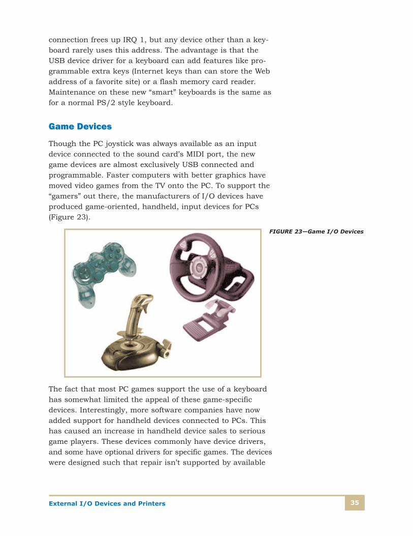
Game Devices
Though the PC joystick was always available as an input
device connected to the sound card’s MIDI port, the new
game devices are almost exclusively USB connected and
programmable. Faster computers with better graphics have
moved video games from the TV onto the PC. To support the
“gamers” out there, the manufacturers of I/O devices have
produced game-oriented, handheld, input devices for PCs
(Figure 23).
The fact that most PC games support the use of a keyboard
has somewhat limited the appeal of these game-specific
devices. Interestingly, more software companies have now
added support for handheld devices connected to PCs. This
has caused an increase in handheld device sales to serious
game players. These devices commonly have device drivers,
and some have optional drivers for specific games. The devices
were designed such that repair isn’t supported by available
FIGURE 23—Game I/O Devices
External I/O Devices and Printers36
documentation. A service technician can disassemble one of
these devices and make some base-level repairs (like recon-
necting a cable or replacing a spring). Recommending whether
a handheld device should be repaired or a new device be pur-
chased is a choice that the service technician needs to make
on a device-by-device basis. Maintenance on these devices is
limited to updating device drivers, keeping the device clean,
and keeping it away from heat sources.
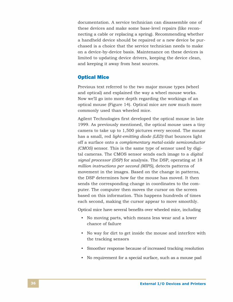
Optical Mice
Previous text referred to the two major mouse types (wheel
and optical) and explained the way a wheel mouse works.
Now we’ll go into more depth regarding the workings of an
optical mouse (Figure 14). Optical mice are now much more
commonly used than wheeled mice.
Agilent Technologies first developed the optical mouse in late
1999. As previously mentioned, the optical mouse uses a tiny
camera to take up to 1,500 pictures every second. The mouse
has a small, red light-emitting diode (LED) that bounces light
off a surface onto a complementary metal-oxide semiconductor
(CMOS) sensor. This is the same type of sensor used by digi-
tal cameras. The CMOS sensor sends each image to a digital
signal processor (DSP) for analysis. The DSP, operating at 18
million instructions per second (MIPS), detects patterns of
movement in the images. Based on the change in patterns,
the DSP determines how far the mouse has moved. It then
sends the corresponding change in coordinates to the com-
puter. The computer then moves the cursor on the screen
based on this information. This happens hundreds of times
each second, making the cursor appear to move smoothly.
Optical mice have several benefits over wheeled mice, including
• No moving parts, which means less wear and a lower
chance of failure
• No way for dirt to get inside the mouse and interfere with
the tracking sensors
• Smoother response because of increased tracking resolution
• No requirement for a special surface, such as a mouse pad

External I/O Devices and Printers 37
The term optical mouse has been used since the inception of
the mouse as a pointing device. The original optical-mouse
technology bounced a focused beam of light off a highly
reflective mouse pad, imprinted with a grid of dark lines,
then into a sensor. Each time the mouse was moved, the grid
interrupted the beam of light and the sensor sent a signal to
the computer. The screen cursor moved a preset amount in
response to the amount and direction of the interruptions.
This kind of optical mouse required the user to orient it at
the correct angle to ensure light beam and sensor alignment.
Scratches and solvents could also damage the mouse pad,
rendering the mouse useless until a replacement pad was
purchased.
Monitors
A compound USB device that’s growing in popularity is the
USB monitor. As stated earlier, a compound device combines
an I/O device with a USB hub. The monitor plugs into a USB
port instead of the standard monitor port on your system or
video board. A nice feature of the USB monitor is that a
powered USB port is included with the monitor (usually at
the base). Having a powered USB port accessible from the
front of your PC is a nice feature, especially for PCs that are
installed into a desk that allows little or no access to the
back of the PC. One disadvantage of USB monitors is that
they don’t always support the same amount of video memory
or some graphics accelerator functions.
Scanners
Technology has advanced to the point that there are full-color
scanners that connect to a PC using a USB cable (Figure 24).
This type of scanner eliminates the need for the device-specific
PCI card and the chance of resource conflicts. Scanners use a
Technology Without an Interesting Name (TWAIN) device driver
and interface. This can cause problems with other TWAIN
installed devices.
The lowered cost of scanners has moved them from business
desktops to home use I/O devices. Scanners using optical
character recognition (OCR) software have eliminated the need

External I/O Devices and Printers38
to reenter typed data. This technology enables you to take
printed documents, scan them, convert the raw data to text,
and edit the file with a word processor. Scanners also have
the ability to do a full-color scan of a photograph and store it
in a graphic file for output on a color printer. With advertised
resolutions up to 9,600 � 9,600 and a color depth of 36 bits,
these scanners record information at a higher resolution than
color film, and much higher than most printers can reproduce.
To achieve hardware resolution with a horizontal sampling
rate of 9,600 would require an array of 81,600 sensors. If you
look at the specifications for these scanners, the 9,600 reso-
lutions are listed as a software-enhanced or interpolated
resolution. Interpolation is a process that the scanning soft-
ware uses to create extra pixels in between the ones actually
scanned by the array. These extra pixels are an average of
the adjacent pixels.
Another term used when talking about scanners is color
depth. This refers to the number of colors that the scanner is
capable of reproducing. Each pixel requires 24 bits to create
the standard true color palette of more than 16,000,000
colors (the human eye can perceive only a few million). Almost
all scanners on the market today support this. Many new
scanners offer bit depths of 30 or 36 bits. They still output
only in 24-bit color, but perform internal processing to select
the best possible choice out of the colors available in an
increased palette. It’s questionable whether the human eye
can tell the difference between 24-bit and 36-bit color.
FIGURE 24—Scanner

External I/O Devices and Printers 39
Desktop Video Cameras
Technology has reduced both the size and the cost of desktop
video cameras, commonly called Web cams (Figure 25). These
small devices have become common I/O devices that are con-
nected to business or home PCs. Connection of these devices
is through a USB cable. Since there’s a severe limit on the
amount of power available through a USB cable, some of these
cameras are self-powered, using batteries and/or plug-in AC
adapters. Check the USB connection of your system for the
power available, before you decide if you need a bus-powered
or a self-powered camera. Many monitors, and most laptop
computers, now include built-in Web cams (Figure 26).
Because of their small size and relatively
low price, these cameras are used for many
business and home applications. Common
uses include video conferencing, digital pho-
tography, and security. In the photographic
and security modes, these cameras use the
TWAIN interface. The software controlling
the camera then converts the files into
Joint Photographic Experts Group (JPEG)
files, which you can store on your com-
puter or share on the Web. Some software
packages can set the camera to take a pic-
ture when movement is detected, or at set
intervals. This makes these inexpensive
devices perfect for home or small-office
security.
FIGURE 25—Desktop Video Cameras or “Web Cams”
Webcam
FIGURE 26—A Web Cam Built into a Monitor

External I/O Devices and Printers40
In the video mode, these cameras use many different software-
driven products to create a video. There are many competing
formats for video presented on a PC running Windows (AVI,
Divx, and QuickTime to name a few). There are also software
products created for these Web cams that produce a video
stream that can be broadcast over the Internet. Common
Intermediate Format (CIF) is the video format commonly used
in videoconferencing. It supports a data rate of 30 frames per
second (fps), with 288 lines and 352 pixels per line. When
using a telephone line, another standard format for video-
conferencing, Quarter Common Intermediate Format (QCIF), is
used. This standard transfers one-fourth the amount of data,
or 144 lines and 176 pixels per line.
Professional Tip
Desktop video cameras using a TWAIN interface can cause problems
when installed with a scanner that also uses the TWAIN interface.
Often, even using USB technology, a desktop video camera and a
scanner connected to the same system causes a resource conflict.
If the camera is selected as the enabled TWAIN device, it will turn
on when you try to scan a document. This causes concern when
the scanner doesn’t cycle up, but you notice the camera turn on
and take a picture. Switching the enabled device on the Device
Manager screen or through your application software solves this
problem.

External I/O Devices and Printers 41
Self-Check 2
1. List three methods that are commonly used to connect a keyboard to the PC.
__________________________________________________________
__________________________________________________________
__________________________________________________________
2. True or False? The best way to clean the ball of a mouse is to use isopropyl alcohol.
3. List three advantages of a flat-panel display over a CRT display.
__________________________________________________________
__________________________________________________________
__________________________________________________________
4. A/an _______ card has its own processor and can produce high-quality graphics quickly.
5. Adding or removing a device from a PC without turning off power is known as _______.
Check your answers with those on page 55.

External I/O Devices and Printers42
PRINTERSThe printer is the most common and most repairable category
of I/O device. Printers range from simple dot-matrix line
printers to full-color laser printers. In this part of your study
unit, we’ll show you how to support and fix printers as well
as how to connect them into system workgroups. We’ll also
discuss color management, which deals with the problems of
color inconsistency across devices and software. Here you’ll
learn what causes color problems and how color management
tools can help alleviate these problems.
Laser PrintersLaser printers are electro-photographic printers that come in
a wide variety for various uses. Small low-volume personal
printers are usually connected to a single PC, while larger
high-volume printers are often found in networks where they
serve many PCs. Figure 27 shows a laser printer that’s
intended for high-volume use.
FIGURE 27—LaserJet Printer

External I/O Devices and Printers 43
Laser printers work by placing an electrostatic charge on a
photosensitive drum that changes its electrical conductivity
only in areas where light strikes it. The drum’s surface is
normally insulated from ground, except in areas where light
strikes it, changing electrostatic charges placed on it by the
primary charging roller. The printing principle is based on the
fact that like charges repel, and unlike charges attract.
Figure 28 shows the internal workings of a laser printer.
All major components for most laser printers are self-contained
and user-replaceable. It’s unlikely a computer technician will
be called to address printer problems. However, understand-
ing printer fundamentals can be helpful. The following is a
brief step-by-step overview of the laser-printing process.
Front ofLaser Printer
Erase Lamps
Mirror
Red Filter
PrimaryGrid
Primary Corona Wire
RubberCleaning
Blade
FusingRoller
Cleaner
FusingLamp
SweeperUsed Toner
Paper
LowerFusingRoller
UpperFusingRoller
Feeder BeltStatic
ChargeEliminator
Transfer Corona Wire
Photosensitive DrumRegistration
Rollers
Pick–Up Roller
Cartridge
Developing Magnet
Developing Cylinder
Fresh Toner
Blade
Spinning Scanning Mirror
FIGURE 28—Inside a Laser Printer

External I/O Devices and Printers44
Cleaning. The drum is physically wiped clean of any residual
toner with a plastic blade and electrically cleaned of residual
static charges by an eraser lamp.
Conditioning. The drum is conditioned by the primary
charging roller to a uniform static charge. The charge is
usually negative and the same voltage as that of the toner.
Writing. Laser light beams striking the drum cause that
area of the drum’s surface to conduct to ground in propor-
tion to the light’s intensity. This causes those areas on the
drum to become more positive than the negatively charged
toner.
Developing. The negatively charged toner is electrostatically
attracted to the more positive areas of the drum that were
exposed to the laser beam light. The negatively charged toner
is repelled from the negatively charged area of the drum that
wasn’t exposed to the laser light.
Transfer. A positive charge draws the negatively charged
toner off the drum and onto the paper.
Fusing. Heat and pressure bond the microscopic bits of
toner to the fibers of the paper.
Color Laser PrintersOriginally, most laser printers were limited to one color of
toner, but with lower costs and higher demand for color, the
color laser is in many more homes and offices (Figure 29).
Color laser printers work the same way as their monochrome
predecessors, except they go through the printing process
four times. This requires one pass each for cyan, magenta,
yellow, and black. By combining these four basic printing
colors in different proportions, the color laser printer produces
all of the colors of the 24-bit “true color” spectrum supported
by Windows. This makes the printing process about four times
more time-consuming. A printer that prints black copies at a
rate of 20 pages per minute (ppm) may process a color page
at about 5 ppm.
There are three main ways of printing in color, each with its
own advantages. Some models have all four toner and devel-
oper units on a wheel. The printer lays down one color of an

External I/O Devices and Printers 45
image and then applies this color to the paper. This type of
printer goes through this process for each color. These print-
ers are the slowest but least expensive. Other printers use
the same process to add all four colors to a plate, and then
transfer the complete image to the paper. This process is also
slow but advertises the fact that the color mix is more exact,
making the output more true-to-life. These printers are usu-
ally in the midpriced range and offer more color management
features. The most expensive printers have a laser assembly,
drum head, and toner system for each color. The paper moves
past the different assemblies, collecting all the colors and
fusing the toner to the paper, creating the final product. This
last type has the fastest paper throughput.
Color laser printers are about the same price as high-speed
or high-resolution monochrome laser printers. Support and
maintenance on a color laser printer commonly costs five or
six times more than that of a comparable monochrome
printer. Three colored and one black toner units need to be
purchased to support color printing. The standard price of
the colored toner can be twice that of the black toner, or
more. With more moving parts inside (sometimes four times
FIGURE 29—A Color LaserPrinter

External I/O Devices and Printers46
as many), annual maintenance contracts for a color laser
printer are commonly one-half the cost of the printer’s pur-
chase price. This makes the color laser printer, even for most
businesses, a sizable investment.
Color Ink-Jet PrintersColor ink-jet printers are relatively inexpensive and are popu-
lar with home users (Figure 30). An ink-jet printer uses a
print head that moves horizontally across the paper, creating
one line of text with each pass. The paper moves vertically in
synchronization with the print head. The print head puts ink
on the paper using a matrix of very small dots.
Single print-head printers create black by combining the three
generic colors of cyan, magenta, and yellow from the color
ink cartridge. Dual-head printers have a black ink cartridge
that makes a richer black on the paper and is much more
economical.
Two factors that affect the quality of ink-jet printer output
are print-head alignment and paper. Print-head alignment is
important because the black and color inks come from differ-
ent cartridges. The cartridges must therefore be aligned to
make the proper color blends. The holes that dispense the
ink can be in different places on every installed cartridge.
Even if only one cartridge is being installed, alignment of the
print heads is required. The printer control panel using the
FIGURE 30—A ColorInk-Jet Printer

External I/O Devices and Printers 47
alignment option handles the alignment of the print heads.
On many ink-jet printers, this control panel is automatically
activated at the administrator’s PC when an ink cartridge is
installed. Follow the instructions on the screen for proper
alignment of the print heads.
The second factor that impacts good color reproduction is the
quality of the paper. The paper should be listed for use in an
ink-jet printer. Many copier papers do support printing on an
ink-jet, but not all. The second thing to look for is the bright-
ness of the paper. The closer the brightness number is to 100,
the closer the paper is to white. Papers labeled as “photo”
paper for ink-jets often have a brightness of 95 or higher and
a glossy surface. Be aware that after printing, the ink on
glossy papers will smear until it dries. Some software applica-
tions take into consideration the brightness of the paper, but
most don’t. If your application allows you to change color
values depending on paper brightness, make sure you set
this value with every change of paper type.
Color Management With advances in technology, every media has moved from
black-and-white to color. The youth of this country have
never seen black-and-white TV shows or magazines. In 1981,
when IBM came out with the PC, the only color on a screen
was CRT green or amber. One of the first major upgrades on
the PC’s list of options was a color screen supporting four
colors. Over the decades, color has become standard on PCs,
with the current standard being the 24-bit true color specifi-
cation. A majority of PCs and their connected displays now
support 24-bit color resolution, or the even higher 32-bit
specification. Almost all Web sites present their materials in
full color.
Having everything in color has become commonplace in the
world of computers, but there’s one problem. The problem is
the challenge of finding a way to get consistent colors from
page to screen to printer. Consistent color across your dis-
play and printer is important to the quality of the documents
you’re creating. Page designers, as well as more casual users,
want to have the images they’ve created look consistent when

External I/O Devices and Printers48
displayed on the monitor, printed, or even posted on the
Internet. Everyone wants a true what-you-see-is-what-you-
get (WYSIWIG, pronounced “wizzy-wig”) image across their
whole computer system. The problem with this is that the
color needs to stay visually consistent between the scanner,
monitor, application software, and final printer output. This
has been very difficult to achieve because of two major road-
blocks: different color systems and different gamuts.
Different Color Systems
White light contains three components of color: red, green,
and blue (RGB). Human eyes perceive color based on how
much of each color reaches them. Monitors and scanners are
based on the additive color system using RGB. Starting at
black, they add red, green, and blue until the desired color is
achieved. The highest levels of all three colors make a color
that’s perceived as white. All images on a monitor, or copied
using a scanner, radiate varying amounts of RGB.
Printers are based on the subtractive color system, usually
using the colors cyan, magenta, yellow, and black (CMYK).
Printed material creates images by reflecting light off of sub-
stances such as ink, dye, wax, and toner. Printers begin with
white (the presence of white light) and subtract RGB to achieve
colors and black. Cyan, for instance, subtracts red and allows
the reflection of green and blue.
Different Gamuts
Each device has a particular range of colors that it’s able to
produce; this is known as the device gamut. The gamut of a
device is determined by the color properties of the device, as
well as the lighting of the room where the device is. A color
monitor can normally reproduce nearly twice as many colors
as a printing press. Knowing this underlines the problem with
color. The picture seen on the monitor can be reproduced on
the Web with good results. Sometimes it even looks good on
the ink-jet or laser output that was coordinated with the
monitor. The problem arises when you send the data file to
the print shop for mass production and the colors change.

External I/O Devices and Printers 49
Another even more bothersome problem can crop up when
the gamut of the same type of device varies. The color man-
agement setup on the application software being used may
need multiple color configurations for different equipment in
the office. For instance, the gamuts of scanners depend on
the process (flatbed, drum, or sheet feed) the scanner uses,
the resolution and color depth supported, and the media
scanned (matte, reflective, or transparent).
If you have a computer I/O device capable of capturing,
displaying, or printing color pages, you’re likely to have expe-
rienced some of the problems in dealing with color on a PC.
Using the color management tools on a particular device
won’t solve all of your problems, but it will allow you to have
more control over the final product.
The use of a color management system (CMS) is recommended
for commercial users of color. A color management system
compensates for the ways different devices handle the same
colors by using profiles to translate color information. With
this technology, colors appear consistent on any device and
application used in the document’s process. This is a com-
plex problem with many differing solutions.
Color Management on Laser and Ink-Jet Printers
Color management on a color laser printer is controlled by
software included with the device driver. The cost of color
printing using a laser printer is high enough to make setting
up the color output well worth the time. You should use a
standard color management tool that can be set to the same
parameters as your application software. The generic Cyan/
Magenta/Yellow/Black Key (CMYK) standard is a good place
to start. Some color laser printers have their own color man-
agement profile. This profile can be installed into most color
graphics programs. Remember, to check the colors that have
been adjusted, a copy must be printed. By carefully tracking
the variables being changed, the cost of this project can be
controlled.
Color management on color ink-jet printers is similar to that
of laser printers. The color reproduction is controlled using
the Color Management tab on the Printer Properties screen.
Adjustments can be made to change the different color bands

External I/O Devices and Printers50
and image quality. The look of these color management panels
is brand specific. Check the documentation that accompanied
your printer for the use of color management features.
Sharing PrintersPrinters can be shared over a network using one of three
methods:
• A printer can be attached to a PC using the PC’s parallel
port. The PC can then share the printer with the network.
• A network printer with embedded logic to manage net-
work communication can be connected directly to a
network.
• A computer dedicated as a print server can control sev-
eral printers connected to a network.
Network print services allow a computer to share a printer
connected to it, and to use printers that are connected to
other computers on the network. In Windows you can share a
printer as easily as sharing a file.
Use the following steps to share a printer using Windows 7:
1. Be sure that file and printer sharing is installed. Click
Start, click Control Panel and then click the Network
and Sharing Center icon. Click Change adapter settings,
right-click the Local Area Connection icon, and click
Properties.
2. If File and Printer Sharing for Microsoft Networks isn’t
listed, click Install to install the feature.
3. Select Service and click Add from the list of network
services, then select File and Printer Sharing for
Microsoft Networks and click OK. You may be asked to
insert the Windows DVD and to reboot.
4. Share the printer by clicking Start and clicking Devices
and Printers. The Devices and Printers window will open.
5. Right-click the printer you want to share. From the
shortcut menu select Printer Properties. Click the
Sharing tab, and click the Share this printer check box.

External I/O Devices and Printers 51
6. In the Share name field, give the printer a share name.
Click OK.
7. The printer should now be listed in the Network
Neighborhood group of other computers on the network.
Products for Network PrintersJetDirect is an installed hardware option with a supported
software component. The JetDirect product is often used in
midsized workgroups that have a number of HP or HP-
compatible printers on their network. The combination of
hardware and software allows your HP printer to become a
print server on your network. When the software is used, it
will find all compatible printers on the network for you. At
this point, an individual with administrator level of security
can configure all of the compatible printers on the network.
JetDirect is designed for use on any supported HP printer with
an EIO slot. JetDirect software supports the connections made
through the JetDirect card’s USB, serial and/or LocalTalk
ports, in addition to the HP printer’s existing parallel port.
You can connect a supported printer to a network that
includes a Windows PC, iMac, Power Mac G3/G4, or UNIX
workstation that uses a serial printer connection.
Practical ExerciseIn this Practical Exercise, you’ll find the color management
scheme used on your monitor and modify some of the
variables. Check your results on page 55.
1. Go to the Color Management screen. You can find this by
clicking on Start, clicking Control Panel, and then click-
ing Display. Next, click Adjust resolution in the left
pane, click on Advanced Settings, then select the Color
Management tab.
2. Click Color Management; this screen will either list the
monitor and profile being used, or show the Color
Management screen for your monitor (Figure 31).

External I/O Devices and Printers52
3. If the Color Management tab displays the current
monitor type and default profile, this is the end of this
exercise.
4. If the screen displays adjustable variables, then make
note of all beginning settings. Modify the settings one at
a time to see the differences.
5. Reset the variables to their original settings.
FIGURE 31—Preset Monitor Profile

External I/O Devices and Printers 53
Self-Check 3
1. What are the six steps of laser printing?
__________________________________________________________
__________________________________________________________
2. True or False? Paper quality has little effect on color printing.
3. What term is used to describe the ability to see on the monitor what the final output will look like?
__________________________________________________________
__________________________________________________________
4. Photo paper for ink-jet printing will normally have a brightness factor of _______ or higher.
5. True or False? Good print quality on an ink-jet printer depends on proper head alignment.
Check your answers with those on page 55.

External I/O Devices and Printers54
NOTES

Self-Check 1
1. PCI (Peripheral Component Interconnect) and PCI-Express
2. I/O controller card
3. False
4. SCSI
5. The SPP allows data flow in only one direction while EPP
is bidirectional.
Self-Check 2
1. PS/2 connector; wireless connector; USB port
2. False
3. Flat-panel monitors take up less space, are lighter, use
less electricity, and have a sharper image.
4. graphics accelerator
5. hot-plugging or hot-swapping
Self-Check 3
1. Cleaning, conditioning, writing, developing, transferring,
and fusing
2. False
3. WYSIWIG (what-you-see-is-what-you-get)
4. 95
5. True
Practical Exercise
Your results will depend on which variable was changed.
Most changes make obvious differences. For example,
changing the green channel will change the amount of
green illumination added to the screen image without
affecting the red or blue channels.
55
Answers
Answers


