20
Studying the combustion of biomass particles using a Lagrangian Method 2 Avril 2014 Frédéric Cordier Sandro Dal-Secco Marcus Charwath

Studying the combustion of biomass particles using a Lagrangian Method
2 Avril 2014
Frédéric CordierSandro Dal-SeccoMarcus Charwath

| 2
Overview1. Motivation
2. Modeling approaches
3. Lagrangian modeling of biomass combustion
4. Results
a) Comparison coal/biomass particle motion
b) Temperature distribution in biomass particles
c) Impact of a non-uniform temperature distribution on the combustion process
d) Slagging
5. Conclusions

| 3
Co-combustion
Negative aspects:
High slagging and fouling tendency
High carbon content in fly and bottom ash
• Combustion of two different fuels in the same
combustion system (e.g. coal (~90% wt) and
biomass (~10% wt)).
Reduction of CO2 emissions
CFD modelling of co-combustion in order
to optimize the combustion process

| 4
Modeling approaches
Lagrangian modeling of the particle movement.
Eulerian modeling of pulverized coal combustion
• Particles are assumed to be sufficiently small to adapt instantly to the local conditions
of the carrier field.
Transport equations are written for the gas/particle mixture assuming a
negligible slip-velocity between the gas phase and the fuel particles
Lagrangian modeling of biomass combustion – a post-processing approach
• Due to the increased inertial forces biomass particles do NOT instantly adapt to the
local conditions of the carrier field
• Mass fractions of biomass are assumed to be small
Post-processing approach

| 5
b) Closure is obtained through the use of a stochastic term
a) Momentum equation for dense particles
where is an increment of the Wiener process and
where
• Particle motion
Langrangian modeling of biomass combustion
• Physicochemical phenomena
a) Particle drying – pressure equilibrium assumption
Mass transfer
Heat transfer
where )( psatvap Tfc =

| 6
Langrangian modeling of biomass combustionb) Devolatilisation – Kobayashi model
Kinetic is given by two competitive reactions
Heat release of the slightly endothermic reactions is neglected
Mass transfer
c) Char combustion -
Mass transfer
Heat release
where )(2,1 pTfk =
where )( pglob TfK =
! All physicochemical phenomena depend on the particle temperature !

| 7
Small particles e.g. coal
(no temperature gradient)
Impact of the particle temperature profile
Large particles e.g. biomass
(temperature gradient)
Raw fuel particle
Dried fuel particle
Char particle Ash particle
Time axis

| 8
Thermal power: 3MWth 10 m long; 1,5m diameter
Inlet Mass flow rate Air (kg/s)
Mass flow rateCoal (kg/s)
Primary air (red) 0,19 0,125Secondary swirled air (green) 0,64 -Tertiary air (blue) 0,58 -
Combustion System

| 9
Three distinct recirculation zones can be observed
Internal recirculation
External recirculation
Results: Flow field characteristics Simulated velocity field of the gas phase obtained using an Eulerian approach.

Results: Coal particle movement Simulated particle motion of coal particles (25µm) using a Lagrangian approach.
! Coal particles are sufficiently small to adapt instantly to local flow field changes !

| 11
Results: Comparison coal/biomass Simulated particle motion of coal (25µm) and biomass (800µm) particles using a
Lagrangian approach.
! Biomass particles do NOT instantly adapt to local flow field changes !Impact on the physicochemical phenomena

| 12
Temperatures in the particle core (layer1) and the most outer layer (layer5); Biomass particles 800µm.
Combustion des particules de biomasse par une méthode Lagrangienne | 10/10/2013
Results: Biomass particle temperature

| 13Combustion des particules de biomasse par une méthode Lagrangienne | 10/10/2013
Results: Impact on devolatilisation Coal mass fraction in the particle core (layer1) and the most outer layer (layer5);
Biomass particles 800µm.
| 14Combustion des particules de biomasse par une méthode Lagrangienne | 10/10/2013
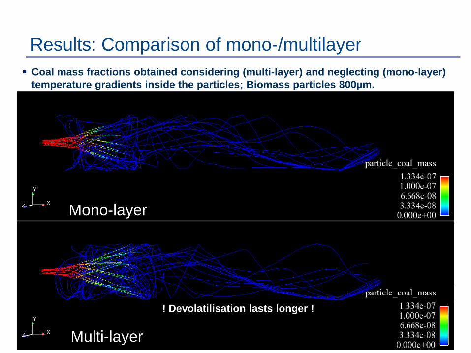
Results: Comparison of mono-/multilayer Coal mass fractions obtained considering (multi-layer) and neglecting (mono-layer)
temperature gradients inside the particles; Biomass particles 800µm.
! Devolatilisation lasts longer !
Mono-layer
Multi-layer

| 15Combustion des particules de biomasse par une méthode Lagrangienne | 10/10/2013
Results: Comparison of mono-/multilayer Char mass fractions obtained considering (multi-layer) and neglecting (mono-layer)
temperature gradients inside the particles; Biomass particles 800µm.
Mono-layer
Multi-layer

| 16
The slagging probability is given by:
Additionally, a critical temperature condition is considered. If the particle temperature is lower than the critical temperature Tc it will not stick to the wall.
Slagging modelsCoal particles
Biomass particles
The slagging probability is a function of the melted ash mass fraction
Additionally, a critical temperature condition is considered. If the particle temperature is lower than the critical temperature it will not stick to the wall
! Not available yet !

| 17Combustion des particules de biomasse par une méthode Lagrangienne | 10/10/2013
Mass flux of deposited particles for several critical temperatures Tc and viscosities µc
µc (Pa s) Tc (K)
Case 1 106 1 173
Case 2 104 1 273
Case 3 768 1 400
Results: Slagging of coal particles
Low deposition rate
High deposition rate

| 18Combustion des particules de biomasse par une méthode Lagrangienne | 10/10/2013
Mass flux of deposited particles for several critical temperatures Tc
Tc
Case 1 900
Case 2 1 000
Case 3 1 402
Results: Slagging of biomass particles
Low deposition rate
High deposition rate

| 19
Slipping velocities between the gas phase and the fuel particles are considered applying the Lagrangian approach Coal particles adapt instantly to local flow field changes. Biomass particles don’t adapt instantly to local flow field changes.
Determination of particle temperature profiles by means of a multilayer model The temperature profile has a significant impact on the devolatilisation process. Better prediction of the particle composition (coal, char, ash and moisture content) at
the outlet. Differences concerning unburned carbon can be neglected.
Implementation of a slagging model which allows to predict the areas where slagging is more likely to occur
Conclusion

| 20Combustion des particules de biomasse par une méthode Lagrangienne | 10/10/2013
Thank you for yourattention


![Combustion of Single Biomass Particles in Air and in Oxy ...digital.csic.es/.../1/Combustion_of_single_Riaza.pdf · investigation [8] revealed that biomass/coal blend combustion may](https://static.documents.pub/doc/80x56/5fbc93e8cbce85303d538edb/combustion-of-single-biomass-particles-in-air-and-in-oxy-investigation-8-revealed.jpg)


