96
The Department of Geodesy and Geoinformatics Stuttgart University Stuttgart University 2011
The Department ofGeodesy and Geoinformatics
Stuttgart UniversityStuttgart University
2011

editing and layout:volker walter, friedhelm krumm, martin metzner, wolfgang scholler

1
Dear friends and colleagues,
It is our great pleasure to present to you this annual report on the 20111 activities and academichighlights of the Department of Geodesy & Geoinformatics of the University of Stuttgart. TheDepartment consists of the four institutes:
� Institute of Geodesy (GIS),
� Institute of Photogrammetry (ifp),
� Institute of Navigation (INS),
� Institute of Engineering Geodesy (IIGS),
and is part of the Faculty of Aerospace Engineering and Geodesy.
Research
This annual report documents our research contributions in many diverse fields of Geodesy &Geoinformatics: from satellite and physical geodesy through navigation, remote sensing, engi-neering surveying and telematics to photogrammetry, geographical information systems and lo-cation based services. Detailed information on projects and research output can be found in thefollowing individual institutes’ sections.
Teaching
Our BSc programme Geodesy & Geoinformatics is currently in its third year of operation. Wewere able to welcome close to 50 new BSc students in Winter Term 2011/2012. The very firstbatch of BSc graduates is expected to finish in Summer 2012. Accordingly the development ofour MSc programme of the same name is being finalized. The Diploma programme is slowlybeing phased out. Total enrolment, in both the BSc and the Diploma programmes, is stable atabout 125 students. In 2011 we have graduated 12 Diploma students. Please visit our websitewww.geodaesie.uni-stuttgart.de for additional information on the programmes.
In its 6th year of existence, our international MSc programme Geomatics Engineering (GEO-ENGINE) has a solid enrolment of 22 students. We attract the GEOENGINE student populationfrom such diverse countries as China, Romania, Palestine, Iraq, Iran, Pakistan, Nigeria, Chile andColombia. Please visit www.geoengine.uni-stuttgart.de for more information.
1A version with colour graphics is downloadable fromhttp://www.ifp.uni-stuttgart.de/publications/jahresberichte/jahresbericht.html

2
Beyond the transition from the old Diploma programme into the BSc/MSc-system we also putmuch effort into a general overhaul of the GEOENGINE programme. The University of Stuttgartis aiming at a so-called system accreditation. This process necessitated an adaptation ofGEOENGINE to conform to the general university’s guidelines for MSc programmes. In fact, westood very much in the spotlight as the accreditation agency selected GEOENGINE as one of onlythree programmes out of the whole range at the University of Stuttgart to be scrutinized for qualityprocesses. Key elements of our redesign are a change from 3 to 4 semesters, a better spreadof credit points over the semesters and the opportunity for more elective courses. The accredita-tion process will continue into 2012. In the mean time we are confident that we can offer a veryattractive GEOENGINE programme also to future students.
Awards and scholarships
We want to express our gratitude to our friends and sponsors, most notably
� Verein Freunde des Studienganges Geodasie und Geoinformatik an der Universitat Stuttgarte.V. (F2GeoS),
� Microsoft company Vexcel Imaging GmbH,
� Ingenieur-Gesellschaft fur Interfaces mbH (IGI),
� DVW Landesverein Baden-Wurttemberg,
who support our programmes and our students with scholarships, awards and travel support.
Below is the list of the recipients of the 2011 awards and scholarships. The criterion for all prizesis academic performance; for some prizes GPA-based, for other prizes based on thesis work.Congratulations to all recipients! We take particular pride that for the second time on row one of ourstudents, Ms. Kan Wang, received the Diploma Thesis Award from the Friends of the University,an award for which she stood in direct competition with theses from the Aerospace EngineeringProgramme.

3
Award Recipient Sponsor ProgrammeKarl-Ramsayer Preis Kan Wang Department of Geodesy Geodesy
& Geoinformatics & GeoinformaticsHarbert-Buchpreis Kan Wang DVW Geodesy
& GeoinformaticsDiploma/MSc Thesis Ali Khosravani F2GeoS GEOENGINE
AwardVordiplompreis Jiawei Yang F2GeoS GeodesyF2GeoS & GeoinformaticsMS Photogrammetry / Xu Wang MS Photogrammetry / GEOENGINE
Vexcel Imaging Vexcel ImagingScholarshipIGI Scholarship Jun Chen IGI mbH GEOENGINE
matching funds Wenjian Qin DAAD GEOENGINE
Jun ChenHamid Gharibi
Diploma Thesis Kan Wang Friends of the All university,Award University of Stuttgart one per faculty
Nico SneeuwAssociate Dean (Academic)[email protected]

4
Institute for Engineering Geodesy 5
Institute for Engineering GeodesyGeschwister-Scholl-Str. 24D, D-70174 Stuttgart,Tel.: +49 711 685 84041, Fax: +49 711 685 84044e-mail: [email protected] [email protected]: http://www.uni-stuttgart.de/ingeo/
Head of Institute
Prof. Dr.-Ing. habil. Volker Schwieger
Secretary
Elke Rawe
Emeritus
Prof. Dr.-Ing. Dr.sc.techn.h.c. Dr.h.c. Klaus Linkwitz
Scientific StaffBara Al-Mistarehi, M.Sc. (since 01.10.2011) Construction ProcessDipl.-Ing. Alexander Beetz Sensor IntegrationShenghua Chen, M.Sc. Kinematic PositioningDipl.-Ing. Jacek Frank (until 30.01.2011) Quality AssuranceDipl.-Ing. Ralf Laufer (until 28.02.2011) Quality AssuranceXiaojing Lin, M.Sc. (since 01.10.2011) Kinematic PositioningDr.-Ing. Martin Metzner Akad. OberratDipl.-Ing. Annette Scheider Engineering GeodesyRainer Schutzle, M.Sc. Information QualityDipl.-Ing. Jurgen Schweitzer Construction ProcessDipl.-Ing. Li Zhang Kinematic PositioningDipl.-Ing. Bimin Zheng Engineering GeodesyZhenzhong Su, M.Sc. (until March 2011) Sensor Integration

6 IIGS
Technical StaffMartin KnihsLars PlateDoris ReichertMathias Stange
External teaching staff
Dipl.-Ing. Thomas Meyer - Landratsamt Ludwigsburg - Fachbereich Vermessung
General View
The Institute of Engineering Geodesy (IIGS) is directed by Prof. Dr.-Ing. habil. Volker Schwieger.It is part of the faculty 6
”Aerospace Engineering and Geodesy“ within the University of Stuttgart.
After having accepted the chair of a Professor for”Engineering Geodesy and Geodetic Mea-
surements“ in the year 2010, Prof. Schwieger became a full member of the German GeodeticCommission (Deutsche Geodatische Kommission - DGK) at the 69th annual meeting of the DGKwhich was held from 23rd to 25th November 2011 in Munich. Furthermore, Prof. Schwieger is amember of the section
”Engineering Geodesy“ within the DGK. He is head of the DVW working
group 3”Measurement Techniques and Systems“ and chairman of the FIG working group 5.4
”Kinematic Measurements“.
In addition to being a member of faculty 6, Prof. Schwieger is co-opted on to the faculty 2”Civil
and Environmental Engineering“. Furthermore, IIGS is involved in the Center for TransportationResearch of the University of Stuttgart (FOVUS). Prof. Schwieger presently acts as speaker ofFOVUS. So, IIGS actively continues the close collaboration with all institutes of the transportationfield, especially with those belonging to faculty 2.
The institute’s main tasks in education focus on geodetic and industrial measurement techniques,kinematic positioning and multi-sensor systems, statistics and error theory, engineering geodesyand monitoring, GIS-based data acquisition, and transport telematics. Here, the institute is re-sponsible for the above-mentioned fields within the curricula of
”Geodesy and Geoinformatics“
(currently Diploma and Bachelor courses of study) as well as for”GEOENGINE“ (Master for Ge-
omatics Engineering in English language). In addition, IIGS provides several courses in Germanlanguage for the curricula of
”Civil Engineering“ (Bachelor and Master) and
”Technique and Econ-
omy of Real Estate“ (Bachelor). To integrate the content of teaching into the master courses of
”Aerospace Engineering“ is presently also one of the main activities. Furthermore, several lec-
tures are given in English to students within the master course”Infrastructure Planning“. Finally,
eLearning modules are applied in different curricula. Also during the year 2011, teaching wascharacterized by the conversion of courses from Diploma to Bachelor and Master degree. This isgoing to continue within the next years.

Institute for Engineering Geodesy 7
The current research and project work of the institute is expressed in the course contents, thusalways presenting the actual state-of-the-art to the students. As a benefit of this, student researchprojects and theses are often effected in close cooperation with the industry. The main researchfocuses on kinematic and static point positioning, analysis of engineering surveying processesand construction processes, machine guidance, monitoring, transport and aviation telematics,process and quality modelling. The daily work is characterized by intensive co-operation withother engineering disciplines, especially with traffic engineering, civil engineering, and aerospaceengineering.
Research and Development
Center for Transportation Research University of Stuttgart (FOVUS)
Since 2011, Prof. Volker Schwieger took over the position as the speaker of the Center for Trans-portation Research from Prof. Ullrich Martin of the Institute of Railway and Transportation Sci-ences. In this regard, also the FOVUS office was moved to the Institute of Engineering Geodesy.Mr. Rainer Schutzle took over as the new FOVUS manager. Main tasks in 2011 were the prepara-tion of the international symposium
”Networks for Mobility“ that will be held in 2012 at the Univer-
sity of Stuttgart. Furthermore, the transportation-related study programs have been re-organized.In this context, the new program
”Transportation Engineering“ has been established. In addition,
joint research proposals related to transportation and mobility have been formulated. All theseactions within FOVUS have been coordinated by the IIGS.
Project EQuiP: Simulation of the Geometric Quality Assurance Process
The project EQuiP (Efficiency Optimization and Quality Control of Engineering Geodesy Pro-cesses in Civil Engineering), which is funded by the german research foundation (DFG) deals withthe efficiency orientated integration of engineering geodesy processes in construction processesin due consideration of measures of quality insurance. In this context, the Institute of EngineeringGeodesy (IIGS) is responsible for the quality assurance.
In the first part of the project (2009-2010) a quality model is developed. It consists of characteris-tics and parameters, which deliver a complete description of the geometric quality of a high-risebuilding. In the second part of the project, exemplified a simulation study for engineering geodesyprocesses is done, on the base of the quality model.
The simulation of an engineering geodesy process was performed, using the Monte Carlo method(MCM), which is a numerical method to solve mathematical problems, using the modeling of ran-dom variables. It also models deterministic and stochastic components and propagates randomvariables through a process or a system. A large number of scattered observations are generatedcomputer-based in a
”virtual experiment“, whose impact on the outcome is determined.
8 IIGS
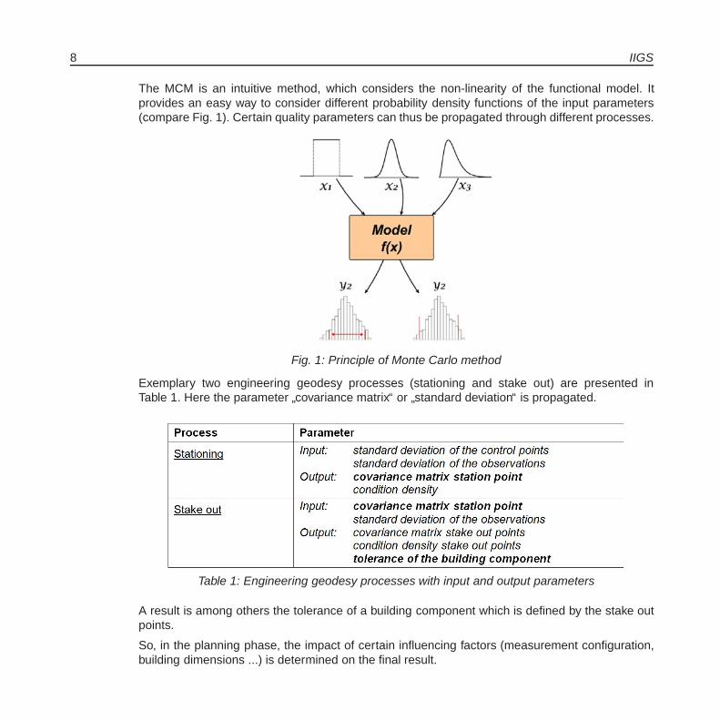
The MCM is an intuitive method, which considers the non-linearity of the functional model. Itprovides an easy way to consider different probability density functions of the input parameters(compare Fig. 1). Certain quality parameters can thus be propagated through different processes.
Fig. 1: Principle of Monte Carlo method
Exemplary two engineering geodesy processes (stationing and stake out) are presented inTable 1. Here the parameter
”covariance matrix“ or
”standard deviation“ is propagated.
Table 1: Engineering geodesy processes with input and output parameters
A result is among others the tolerance of a building component which is defined by the stake outpoints.
So, in the planning phase, the impact of certain influencing factors (measurement configuration,building dimensions ...) is determined on the final result.

Institute for Engineering Geodesy 9
Project QuCon: Real Time Quality Control System for Residential Houses Construction Processes
The EU-project QuCon”Development of a Real Time Quality Support System for the Houses
Construction Industry“ was finalized successfully in 2011. Within this project, a real time qualityassurance tool/software (compare Fig. 2), which is suitable for residential houses constructionprocesses, was developed and then evaluated and improved by the experts and potential users.
Fig. 2: Screenshot of the Software
Using the software, the process and product quality can be documented, accessed and monitoredin real time. The user can have an overview of the current project state through the so-called
”real
time quality index“. In this way, the reasonable decision and remediation can be carried out, sothat the quality of the construction process can be improved and assured in real time.
The project results, the software and the user guidance as well as the user manual were finalizedand delivered to all the project partners. For the dissemination of the project results, an informationevent was held in Cyprus and several papers and presentations were published and made by allthe project partners on a national and international level.
iMobility Working Group on Digital Maps (DMWG)
In succession of the EU-funded ROSATTE project (Road Safety Attribute Exchange Infrastructurein Europe), which was finalized at the end of 2010, a working group within the iMobility Forumwas founded in 2011. This working group mainly consists of national road authorities, commer-cial map vendors, service providers and research institutions that already have been involved inROSATTE. It is aimed to increase the number of road authorities from other EU member states.The working group itself has a steering function and aims to prepare the implementation of thedata exchange infrastructure that was developed within ROSATTE across Europe. This is mainlythe preparation of the legal structure of the ROSATTE implementation platform (RIP) that is tobe built as a self-contained organization and to conduct preparative studies. The eMaPS projectconsortium (eSafety Digital Maps Public Private Partnership Support Action) has been assignedwith the practical realization of these tasks. This project is funded by the European Commissionand mainly consists of DMWG members.

10 IIGS
Although the IIGS is neither a member of DMWG nor of eMaPS, it stays in close cooperationwith these consortia. As in ROSATTE, the IIGS is mainly involved in the quality management andlocation referencing tasks.
Databases for Traffic Road Data Acquisition
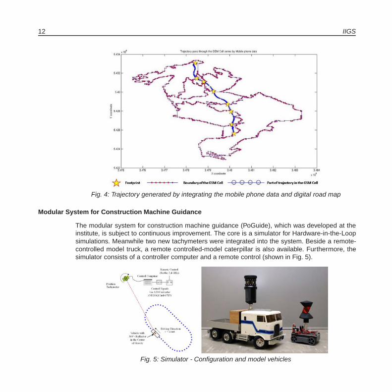
Within the research about traffic state acquisition, the IIGS focused on the databases for trafficroad data acquisition in 2011. Two principally data sources for generation of traffic information arecollected and stored with suitable data structure. These includes the digital road map and cellularphone data.
In the first case (digital road map), the research work chose the Geographic Data File (GDF) asthe standards of digital road map, concerning its worldwide acceptance in the field of research andindustry. According to the data model described in GDF standards, the database build and storesthe digital road map in terms of features, attribute and relationships and geometry. Especially theattributes are important which influence the traffic information collection, like direction of trafficflow, functional road class, intersection type, junction type, and national road class, and so on.
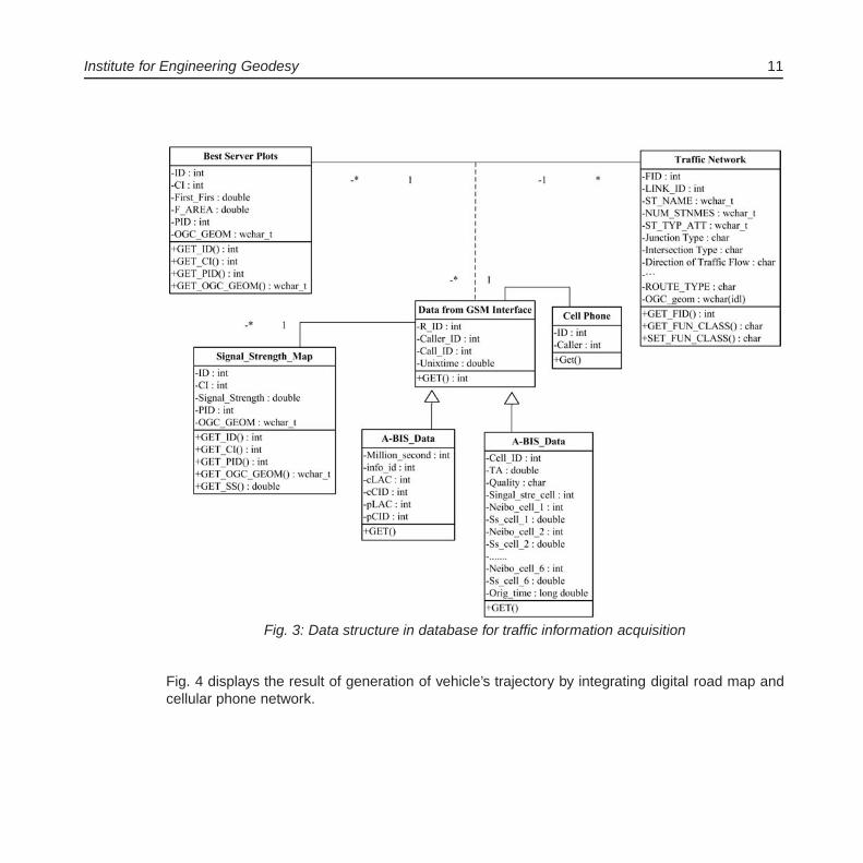
Another part of the databases include the mobile phone data. The data related to this, include astatic and a dynamic part. The static part, like signal strength maps, best server plots and antennapositions maps, and other information of mobile phone network, deals with the infrastructure in-formation about cellular phone network. The dynamic data will be transferred from the so calledA- or the A-bis interface of the mobile phone network. They contain the information of the mobiledevices in the network.
Fig. 3 totally formulates the data structure in database for traffic information acquisition.
Concerning the query function of the database, the work mainly focus on the basic traffic informa-tion queries, including positioning of vehicles, vehicles’ trajectories, traffic incident detection andtraffic volume detection and traffic flow. All of these query function of the database will considerthe positioning interesting object and the time slot. The trajectory of one identified road user (cel-lular phone user) during one period is calculated by exploiting the handover records in A data.Intersection between the digital road map and best sever plots were stored to optimize the spatialquery by decreasing the query space significantly.
Institute for Engineering Geodesy 11
Fig. 3: Data structure in database for traffic information acquisition
Fig. 4 displays the result of generation of vehicle’s trajectory by integrating digital road map andcellular phone network.
12 IIGS
Fig. 4: Trajectory generated by integrating the mobile phone data and digital road map
Modular System for Construction Machine Guidance
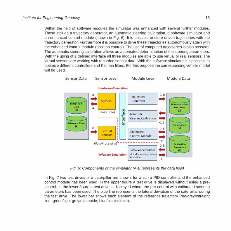
The modular system for construction machine guidance (PoGuide), which was developed at theinstitute, is subject to continuous improvement. The core is a simulator for Hardware-in-the-Loopsimulations. Meanwhile two new tachymeters were integrated into the system. Beside a remote-controlled model truck, a remote controlled-model caterpillar is also available. Furthermore, thesimulator consists of a controller computer and a remote control (shown in Fig. 5).
Fig. 5: Simulator - Configuration and model vehicles
Institute for Engineering Geodesy 13
Within the field of software modules the simulator was enhanced with several further modules.These include a trajectory generator, an automatic steering calibration, a software simulator andan enhanced control module (shown in Fig. 6). It is possible to store driven trajectories with thetrajectory generator. Furthermore it is possible to drive these trajectories autonomously again withthe enhanced control module (position control). The use of computed trajectories is also possible.The automatic steering calibration allows an automated determination of the steering parameters.With the using of a defined interface all three modules are able to use virtual or real sensors. Thevirtual sensors are working with recorded sensor data. With the software simulator it is possible tooptimize different controllers and Kalman filters. For this propose the corresponding vehicle modelwill be used.
Fig. 6: Components of the simulator (A-E represents the data flow)
In Fig. 7 two test drives of a caterpillar are shown, for which a PID-controller and the enhancedcontrol module has been used. In the upper figure a test drive is displayed without using a pre-control. In the lower figure a test drive is displayed where the pre-control with calibrated steeringparameters has been used. The blue line represents the lateral deviation of the caterpillar duringthe test drive. The lower bar shows each element of the reference trajectory (red/grey=straightline; green/light grey=clothoide; blue/black=circle).

14 IIGS
Fig. 7: Comparison of two test drives of a caterpillar without (above) and with (below) pre-control
An enhancement in curve areas is obvious. Altogether, the total RMS (Root Mean Square) canbe improved from 3 mm without pre-control to 2 mm by using a pre-control.
In the future the system shall be used under outdoor conditions, too. For this an outdoor simulatoris presently under construction. Thus it will be possible to also use GNSS-sensors as positionsensors. Further sensors shall be integrated for measurements of inclination and acceleration.With the use of these sensors, dead reckoning will be possible.
Automatic Low-Cost GNSS Monitoring System
Monitoring is one of the main tasks in engineering geodesy. Beside the traditional tachymeter,only GNSS receivers can measure the 3-dimensional positions automatically and continuously.However, the geodetic dual frequency GNSS receivers are not suitable for monitoring a huge
Institute for Engineering Geodesy 15
object, because they are quite expensive (some of them cost more than 20,000 Euro). In therecent years, low-cost single frequency (L1 only) receivers (one costs about 100 Euro) have beenproved that they reach almost the same accuracy as geodetic ones.
Automatic Communication via Wireless Mesh Network (WMN)
An automatic low-cost GNSS monitoring system has been tested at IIGS. Fig. 8 shows theoverview of this system. The test system consists of three stations: a central station (master)and two clients. The master collects continuously raw data from the two clients via WLAN in real-time. The data of all the stations are transferred to the computer at the central station. The dataprocessing is executed there.
Each station has one CabLynx router which is the wireless router and has been configured forrealizing the data transfer via wireless mesh network (WMN). In the classical network topology,the clients can just transfer the data to the master. But in the mesh network, the data transmissionbetween the clients is also possible. After starting the system, IP addresses of the clients are givenby the master automatically and dynamically. With WMN, data of the clients can automatically findtheir own path to reach the master. If there is no direct connection between one client and themaster, the data of this client can be transferred via the other clients in the mesh net until itreaches the master. If one client could not operate, the remaining clients could still communicatewith each other. That means the mesh network, which is self-organized and self-healed, providesa higher reliability and redundancy.
Since the network is self-organized and the data transmission direction is variant and previouslyunknown, an omni-directional antenna (from firma VIMCOM) is necessary here. Additionally, tomake sure that this system can run continuously and autonomously, the power supply of eachstation is provided with one solar panel, one charge controller and one back up battery. The mostimportant parts of the router are the u-blox GPS antenna ANN-MS and the latest-generation u-blox GPS receiver LEA-6T. By using the LEA-6T receiver is possible to output the GPS raw datain binary format (UBX-format).
Data Processing in Post-Processing
The clients transfer data to the master that is connected to a computer for data processing. Sinceall the stations transfer data to the computer through the same port, the belonging of the datashould be identified previously. A program has been written for this purpose, the raw data areidentified by the IP address from which they were sent and stored directly in different files in thecomputer.

16 IIGS
Fig. 8: System architecture
In order to analyze the results using raw data the flowing steps are realized:
� The binary format (UBX format) is transformed to standard exchange format (RINEX format)and edited using the powerful free software TEQC.
� The calculation of the baseline or coordinates of the rover stations related to the referencestation. That can be solved by the GPS software Wa1 from Wasoft.
First Results
Several tests have taken place in April and November 2011 in two test areas in Stuttgart. It has totest the accuracy of this system depending on observation time and shadowing conditions. Here,the results of the test, which was carried out in November as an example, will be presented. Fig.9 shows the test scenarios.
Institute for Engineering Geodesy 17
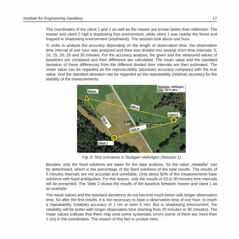
The coordinates of the client 1 and 2 as well as the master are known better than millimeter. Themaster and client 2 had a shadowing free environment, while client 1 was nearby the forest andtrapped in shadowing environment (southwest). The session took about one hour.
In order to analyze the accuracy depending on the length of observation time, the observationtime interval of one hour was analyzed and then was divided into several short time intervals: 5,10, 15, 20, 25 and 30 minutes. For the accuracy analysis, the given and the measured values ofbaselines are compared and their difference are calculated. The mean value and the standarddeviation of these differences from the different divided time intervals are then estimated. Themean value can be regarded as the reproducibility (absolute) accuracy compared with the truevalue. And the standard deviation can be regarded as the repeatability (relative) accuracy for thestability of the measurements.
Fig. 9: Test scenarios in Stuttgart-Vaihingen (Session 1)
Besides, only the fixed solutions are taken for the data analysis. So the value”reliability“ can
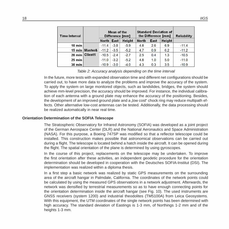
be determined, which is the percentage of the fixed solutions of the total results. The results of5 minutes intervals are not accurate and unreliable. Only about 50% of the measurements havesolutions with fixed ambiguities. For this reason, only the results of 10 to 30 minutes time intervalswill be presented. The Table 2 shows the results of the baseline between master and client 1 asan example.
The mean values and the standard deviations do not become much better with longer observationtime. So after the first results, it is not necessary to have a observation time of one hour, to reacha repeatability (relative) accuracy of 1 cm or even 5 mm. But in shadowing environment, thereliability will be better with longer observation time (starting from 20 minutes or 30 minutes). Themean values indicate that there may exist some systematic errors (some of them are more than1 cm) in the coordinates. The reason of this fact is unclear here.
18 IIGS
Table 2: Accuracy analysis depending on the time interval
In the future, more tests with expanded observation time and different net configurations should becarried out, to have more data to analyze the problems and improve the accuracy of the system.To apply the system on large monitored objects, such as landslides, bridges, the system shouldachieve mm-level precision, the accuracy should be improved. For instance, the individual calibra-tion of each antenna with a ground plate may enhance the accuracy of the positioning. Besides,the development of an improved ground plate and a
”low cost“ chock ring may reduce multipath ef-
fects. Other alternative low-cost antennas can be tested. Additionally, the data processing shouldbe realized automatically in near real time.
Orientation Determination of the SOFIA Telescope
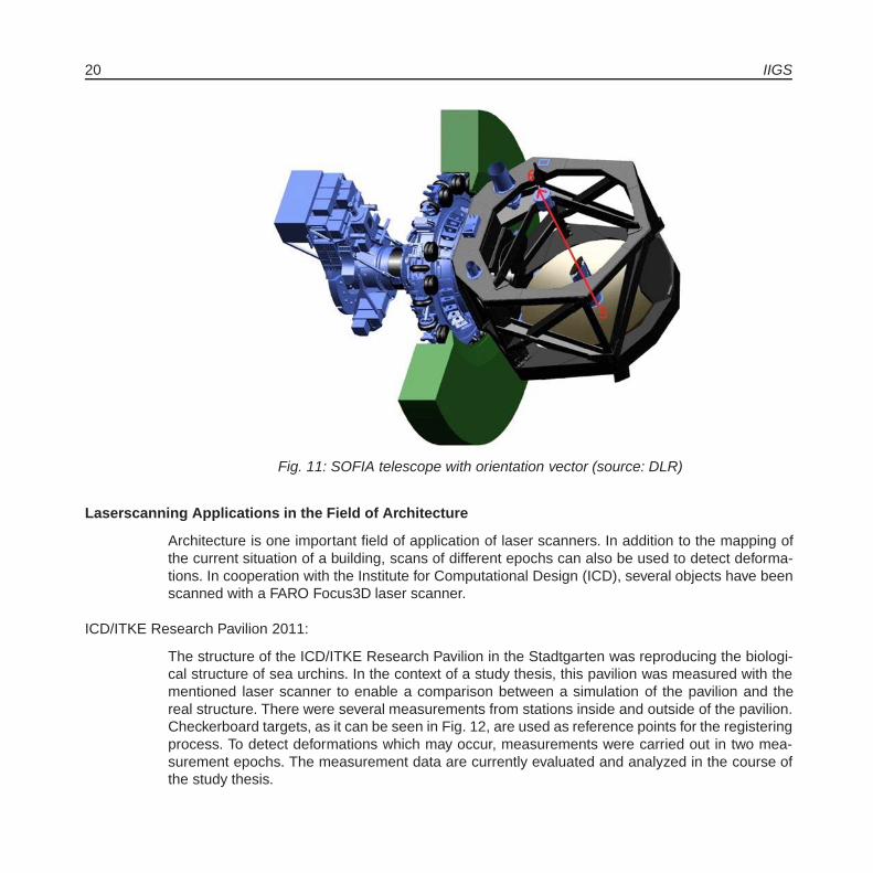
The Stratospheric Observatory for Infrared Astronomy (SOFIA) was developed as a joint projectof the German Aerospace Center (DLR) and the National Aeronautics and Space Administration(NASA). For this purpose, a Boeing 747SP was modified so that a reflector telescope could beinstalled. This construction makes possible that astronomical observations can be carried outduring a flight. The telescope is located behind a hatch inside the aircraft. It can be opened duringthe flight. The spatial orientation of the plane is determined by using gyroscopes.
In the course of this project, replacements on the telescope may be undertaken. To improvethe first orientation after these activities, an independent geodetic procedure for the orientationdetermination should be developed in cooperation with the Deutsches SOFIA-Institut (DSI). Theimplementation was realized within a diploma thesis.
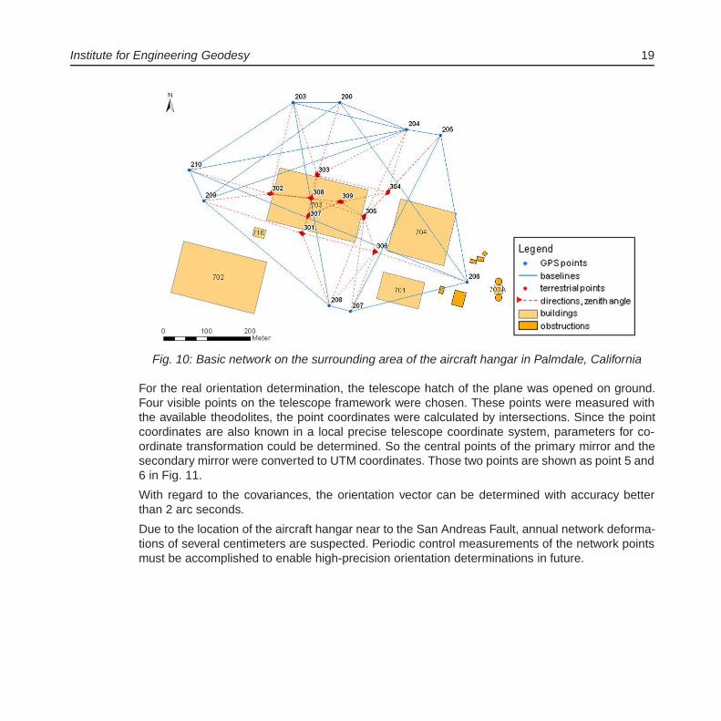
In a first step a basic network was realized by static GPS measurements on the surroundingarea of the aircraft hangar in Palmdale, California. The coordinates of the network points couldbe calculated by using the measured GPS observations in a network adjustment. Afterwards, thenetwork was densified by terrestrial measurements so as to have enough connecting points forthe orientation determination inside the aircraft hangar (see Fig. 10). The used instruments areGNSS receivers (system 1200) and industrial theodolites (TM5100A) from Leica Geosystems.With this equipment, the UTM coordinates of the single network points has been determined withhigh accuracy. The standard deviation of Eastings is 1-3 mm, of Northings 1-2 mm and of theheights 1-3 mm.
Institute for Engineering Geodesy 19
Fig. 10: Basic network on the surrounding area of the aircraft hangar in Palmdale, California
For the real orientation determination, the telescope hatch of the plane was opened on ground.Four visible points on the telescope framework were chosen. These points were measured withthe available theodolites, the point coordinates were calculated by intersections. Since the pointcoordinates are also known in a local precise telescope coordinate system, parameters for co-ordinate transformation could be determined. So the central points of the primary mirror and thesecondary mirror were converted to UTM coordinates. Those two points are shown as point 5 and6 in Fig. 11.
With regard to the covariances, the orientation vector can be determined with accuracy betterthan 2 arc seconds.
Due to the location of the aircraft hangar near to the San Andreas Fault, annual network deforma-tions of several centimeters are suspected. Periodic control measurements of the network pointsmust be accomplished to enable high-precision orientation determinations in future.
20 IIGS
Fig. 11: SOFIA telescope with orientation vector (source: DLR)
Laserscanning Applications in the Field of Architecture
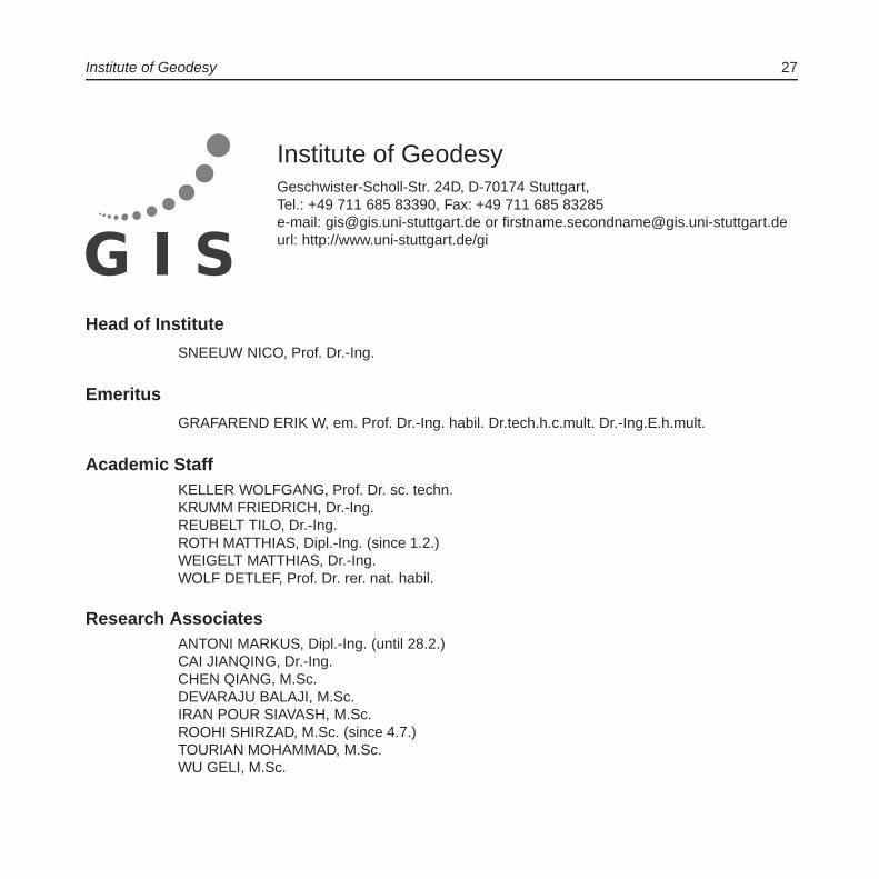
Architecture is one important field of application of laser scanners. In addition to the mapping ofthe current situation of a building, scans of different epochs can also be used to detect deforma-tions. In cooperation with the Institute for Computational Design (ICD), several objects have beenscanned with a FARO Focus3D laser scanner.
ICD/ITKE Research Pavilion 2011:
The structure of the ICD/ITKE Research Pavilion in the Stadtgarten was reproducing the biologi-cal structure of sea urchins. In the context of a study thesis, this pavilion was measured with thementioned laser scanner to enable a comparison between a simulation of the pavilion and thereal structure. There were several measurements from stations inside and outside of the pavilion.Checkerboard targets, as it can be seen in Fig. 12, are used as reference points for the registeringprocess. To detect deformations which may occur, measurements were carried out in two mea-surement epochs. The measurement data are currently evaluated and analyzed in the course ofthe study thesis.

Institute for Engineering Geodesy 21
Fig. 12: Single Scan of measuring the Research Pavilion
Aggregate Architectures
Measurements of delicate aggregate structures are another field of application for the laser scan-ner. The term aggregate architectures specifies a system of loosely-coupled individual elements.At ICD, such (architectonical) systems are simulated and realized by dumping numerous elements(> 100) with a robotic arm concurrently.
The structure must be determined metrologically to compare the simulated and the real structure.Because of the large number of individual elements and the resulting size of the structure, a lami-nar measurement is performed by using the laser scanner. The spatial orientation of the individualelements shall be detected by analyzing the created point cloud. Currently, single elements (e.g.Fig. 13) or small groups have already been measured in first experiments. Because of the slightbreadth of the structure heads (ca. 2 mm), the full resolution of the laser scanner is utilized. Es-pecially at the edges, there is a problem with flawed measurements. As it is shown in Fig. 14, themeasured point cloud can be used to calculate the coarse axis orientation with appropriate algo-rithms. Actually the algorithms are developed further to detect the single axis of more complexstructures.

22 IIGS
Fig. 13: Individual element of the aggregate structure
Fig. 14: Point cloud with determined axis orientation
Activities of Prof. Dr.-Ing.Dr.sc.techn.h.c.Dr.h.c. Klaus W. Linkwitz in 2011:Formfinding of Lightweight Surface Structures
During the winter semester 2010/2011 the compact course”Formfinding of Lightweight Tension
Structures“ was incorporated into the 4-semester Master Course”Computational Mechanics of
Materials and Structures (COMMAS)“ for foreign students and was given from 14th to 20th Febru-ary 2011.The lecture, consisting of 32 weekly hours and the exercises comprising 16 weeklyhours per semester were given from Mondays to Fridays all-day and on Saturdays and Sundayshalf-day.

Institute for Engineering Geodesy 23
The additional appertaining practical computer exercises were performed on Windows XP com-puters in the CIP pool of the course
”Water Resource Engineering and Management (WAREM)“
of the department”Civil and Environmental Engineering“ in the University Campus Pfaffenwald in
Vaihingen. The exercises were intensified, since a final graded project-work was demanded fromthe students.
Prof. Linkwitz visited the Technical University of Donetsk, Ukraine on the occasion of its 90thbirthday. During his visit he spent several days in the institute of Prof. Mogilny to gain an insightinto the entire scope of the scientific work.
Moreover, Prof. Linkwitz gave a lecture on the”Effective Education of Engineers and Geodesists“
at the University of Donetsk.
Publications
Beetz, A., Czommer, R., Schwieger, V.: Signalstarken-Matching und Map-Aiding-Methodenzur Positionsbestimmung von Mobilfunkteilnehmern in Echtzeit fur Verkehrsprognosen.Zeitschrift fur Vermessungswesen, Jahrgang 136, Heft 3/2011. S. 150-164, 2011.
Linkwitz, K.: Experiences and Results of Observing the Long-Time Shape Behaviour of a ThinWidespanning Grid-Shell-Membrane-like Interaction of Shape and Load-bearing Capacity.In: 5th International Conference on Textile Composites and Inflatable Structures STRUC-TURAL MEMBRANES 2011 E. Onate, B. Kroplin and K.-U.Bletzinger (Eds), Barcelona,04.-08.10.2011
Schweitzer, J.; Schwieger, V.: Modeling of Quality for Engineering Geodesy Processes in CivilEngineering. In: Journal of Applied Geodesy, Vol. 5, Heft 1/2011, S. 13-22, 2011.
Schwieger, V., Heunecke, O.: DIN 18709, Teile 4 und 5, zur Ausgleichungsrechnung,Statistik und Auswertung kontinuierlicher Messreihen erschienen. Allgemeine Vermes-sungsnachrichten, Jahrgang 118, Heft 08-09/2011, S. 313-315, 2011.
Schwieger, V.: Positionsbestimmung von Fahrzeugen, Themenheft Forschung Nr. 7”Intelligente
Fahrzeuge“, Rektor der Universitat Stuttgart, Stuttgart 2010/11.
Weston, N.D., Schwieger, V.: Cost effective GNSS positioning techniques. Coordinates, Vol. VII,Issue 6, pp 7-11, June 2011.
Zhang, L., Schwieger, V.: Ein Echtzeit-Qualitatskontrollsystem fur Wohnhausbauprozesse. Allge-meine Vermessungsnachrichten, Jahrgang 118, Heft 11-12/2011, S. 368-380, 2011.
Zhang, L., Schwieger, V.: Real Time Quality Assurance Indexes for Residential House Construc-tion Processes. FIG Working Week, Marrakesch, Marokko, 18.-22.05.2011.

24 IIGS
Presentations
Linkwitz, K.:”Zur aktuellen Ausbildung des Ingenieurs und Geodaten“, 90 Jahre Technische Uni-
versitat Donetsk, Technische Universitat Donetsk Ukraine 27.05.-09.06.2011
Schwieger, V.: Interdisziplinare Herausforderungen der Ingenieurgeodasie. Antrittsvorlesung imRahmen des Geodatischen Kolloquiums der Universitat Stuttgart, 04.02.2011
Schwieger, V., Zhang, L., Schweitzer, J.: Quality Models and Quality Propagation in ConstructionProcesses. Geo-Siberia, Nowosibirsk, Russland, 27.-29.04.2011.
Schwieger, V.: Construction Machine Guidance at University Stuttgart. Technical University ofConstruction Bucharest, Rumanien, 07.11.2011.
Schwieger, V.: Quality Evaluation and Geo-Referencing. Technical University of ConstructionBucharest, Rumanien, 08.11.2011.
Schwieger, V.: Quality in Engineering Geodesy Processes. Technical University of ConstructionBucharest, Rumanien, 08.11.2011.
Schwieger, V.: Map Matching Applications. Seminar SE 3.05”GPS/INS-Integration und
Multisensor-Navigation“, Carl-Cranz-Gesellschaft e.V., Oberpfaffenhofen, 16.11.2011.
Doctorates
Laufer, Ralf: Prozedurale Qualitatsmodellierung und -management fur Daten - ingenieur-geodatische und verkehrstechnische Anwendungen (Hauptberichter: Prof. Dr.-Ing. habil. V.Schwieger, Mitberichter: Prof. Dr.-Ing. habil. D. Fritsch.) Published: Bayerische Akademieder Wissenschaften, Verlag C. H. Beck, DGK, Reihe C, Nr. 662
Diploma Thesis
Gao, Yang: Positionsbestimmung fur verschiedene Bewegungsmodelle mittel Kalman Filter
Haußmann, Susanne: Orientierungsbestimmung fur das SOFIA-Teleskop (in Kooperation mit DSI)
Rosca, Alexandra: Vergleich von drei GPS Auswertesysteme - Leica Geo Office, GIPSY OASIS(GOA II) und WA1
Scheiblauer, Brigitte: Erstellung eines Feldkalibrierverfahrens fur das Messsystem”Tiger“ der Fa.
Angermeier in Kooperation mit der Firma ANGERMEIER INGENIEURE GmbH.
Wu, Bohan: Evaluierung und Weiterentwicklung eines Verfahrens zur Klassifikation von Fahrbah-nen nach Oberflachengute mittels Seriensensorik

Institute for Engineering Geodesy 25
Master Thesis
Roman, Maria Alexandra:”Commissioning and Investigations regarding a Low-cost GPS Monitor-
ing System“, in collaboration with Faculty of Geodesy (Technical University of Civil Engi-neering Bucharest)
Zhang, Yin: Sensor Integration and Enhancement of a KALMAN-Filter for a Construction MachineSimulator
Education
Basic Geodetic Field Work (Zhang, Stange) 5 daysGeodetic Measurement Techniques II (Zhang) 0/1/0/0Geodetic Measurement Techniques I (Metzner, Zhang) 3/1/0/0Integrated Field Work (in German) (Metzner, Zheng) 10 daysStatistics and Error Theory (Schwieger, Zhang) 2/2/0/0Surveying Engineering in Construction Process (Schwieger, Zheng) 3/1/0/0Surveying Engineering II (Schwieger, Zheng) 2/1/0/0Surveying Engineering III (Schwieger, Beetz) 2/1/0/0Surveying Engineering IV (Schwieger, Beetz) 2/1/0/0Thematic Cartography (in German) (Beetz, Scheider) 1/1/0/0Multisensor Systems for Terrestrial Data Acquisition (in German) (Schwieger, Schweitzer) 1/1/0/0Transport Telematics (in German) (Metzner, Schutzle, Scheider) 2/1/0/0Reorganisation of Rural Regions (Meyer) 1/0/0/0Integrated Field Work (Metzner, Zheng) 10 daysTerrestrial Multisensor Data Acquisition (Schwieger, Schutzle) 2/1/0/0Thematic Cartography (Schutzle) 1/1/0/0Transport Telematics (Metzner, Schutzle, Schweitzer) 2/1/0/0Kinematic Measurements and Positioning (Schwieger, Beetz) 2/1/0/0Acquisition and Management of Planning Data (Metzner, Stange) 2/1/1/0GIS-based Data Acquisition (Schwieger, Schweitzer) 1/1/0/0Data Management and Analysis (Metzner, Beetz) 1/1/0/0Geodesy in Civil Engineering (Metzner, Scheider) 2/2/0/0Geoinformationsystems (Metzner, Beetz) (2/1/0/0)

26 IIGS
Institute of Geodesy 27
Institute of GeodesyGeschwister-Scholl-Str. 24D, D-70174 Stuttgart,Tel.: +49 711 685 83390, Fax: +49 711 685 83285e-mail: [email protected] or [email protected]: http://www.uni-stuttgart.de/gi
Head of Institute
SNEEUW NICO, Prof. Dr.-Ing.
Emeritus
GRAFAREND ERIK W, em. Prof. Dr.-Ing. habil. Dr.tech.h.c.mult. Dr.-Ing.E.h.mult.
Academic StaffKELLER WOLFGANG, Prof. Dr. sc. techn.KRUMM FRIEDRICH, Dr.-Ing.REUBELT TILO, Dr.-Ing.ROTH MATTHIAS, Dipl.-Ing. (since 1.2.)WEIGELT MATTHIAS, Dr.-Ing.WOLF DETLEF, Prof. Dr. rer. nat. habil.
Research AssociatesANTONI MARKUS, Dipl.-Ing. (until 28.2.)CAI JIANQING, Dr.-Ing.CHEN QIANG, M.Sc.DEVARAJU BALAJI, M.Sc.IRAN POUR SIAVASH, M.Sc.ROOHI SHIRZAD, M.Sc. (since 4.7.)TOURIAN MOHAMMAD, M.Sc.WU GELI, M.Sc.
28 GIS
Administrative/Technical StaffHOCK MARGARETE, Phys. T.A.SCHLESINGER RON, Dipl.-Ing. (FH)VOLLMER ANITA, Secretary
GuestsABDEL-MONEM M, Dr., Cairo/Egypt (16.8.-14.11.)BOLTE B, Kiel (5.10.)BORKOWSKI A, Prof., Wroclaw/Poland (27.4.-7.5.)EINSPIGEL D, Prague/Czech Republic (17.9.-30.10.)HAGEDOORN J, Dr., Potsdam (1.-4.11.)KLEMANN V, Dr., Potsdam (17.-21.10.)MARTINEC Z, Prof. Dr., Dublin/Ireland (1.9.-25.11.)RAJAPPAN R, Chennai/India (3.5.-24.6.)SHARIFI MA, Prof. Dr., Tehran/Iran (4.7.-25.8.)VARGA P, Prof. Dr., Budapest/Hungary (6.6.-1.7., 3.11.-3.12.)VISHWAKARMA BD, Roorkee, Uttarakhand/India (since 17.10.)YOU RJ, Prof. Dr., Tainan/Taiwan (16.3.-13.5.)ZHANG S, Dr., Wuhan/China (since 2.3.)
Additional LecturersENGELS J, PD Dr.-Ing. habil., StuttgartHAUG G, Dr.-Ing., Stadtplanungs- und Stadtmessungsamt, Esslingen/NeckarSCHONHERR H, Prasident Dipl.-Ing., Landesamt fur Geoinformation und Landentwicklung
Baden-Wurttemberg, Stuttgart
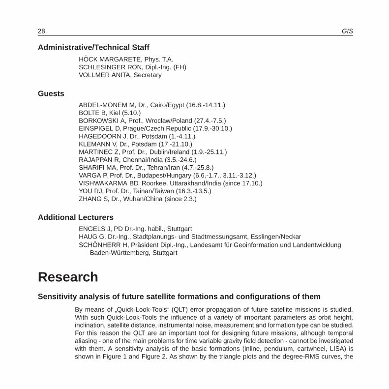
ResearchSensitivity analysis of future satellite formations and configurations of them
By means of”Quick-Look-Tools“ (QLT) error propagation of future satellite missions is studied.
With such Quick-Look-Tools the influence of a variety of important parameters as orbit height,inclination, satellite distance, instrumental noise, measurement and formation type can be studied.For this reason the QLT are an important tool for designing future missions, although temporalaliasing - one of the main problems for time variable gravity field detection - cannot be investigatedwith them. A sensitivity analysis of the basic formations (inline, pendulum, cartwheel, LISA) isshown in Figure 1 and Figure 2. As shown by the triangle plots and the degree-RMS curves, the

Institute of Geodesy 29
advanced formations are able to improve the sensitivity by approximately one order of magnitudecompared to the inline-formation. Additionally, these formations lead to a higher isotropy as shownby the covariance functions in Figure 2. The North-South structures caused by the inline-formationare eliminated and isotropic circular covariance patterns appear. The higher isotropy is also visiblein the triangle plots of formal errors, where the accuracy of spherical harmonic coefficients ofhigher order is improved.
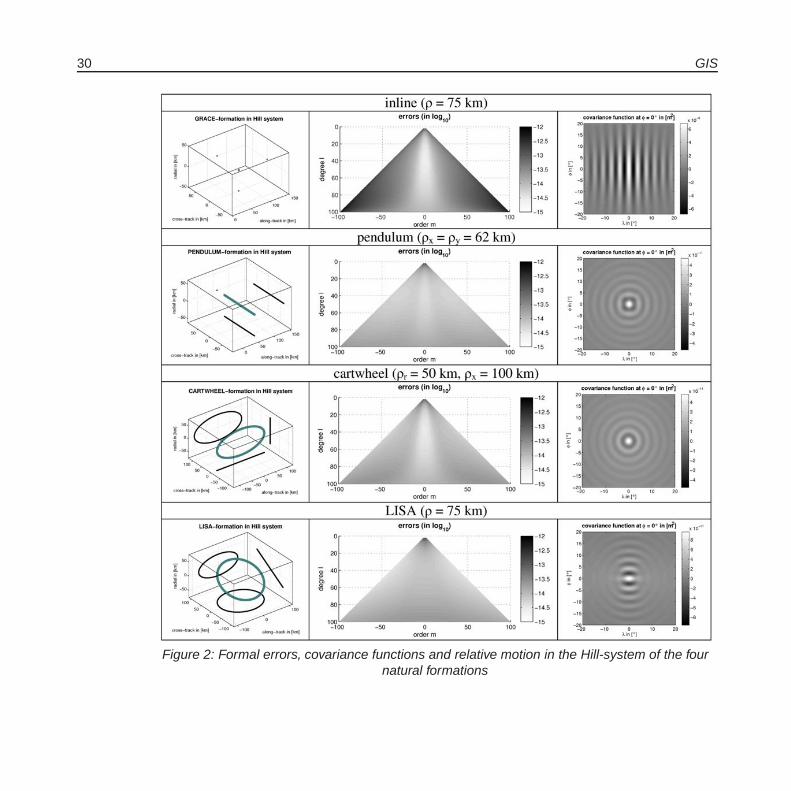
One of the ideas for a future mission design is to combine formations in different inclinations (andrepeat patterns), the so-called Bender-design. It was already shown by several studies that sucha design has capabilities for temporal de-aliasing and advantages concerning sensitivity, espe-cially for short estimation periods, e.g. 4 or 7 days. By means of Quick-look-tools, the sensitivityof Bender-designs can be studied. Figure 3 and Figure 4 show the results of a sensitivity analysisof Bender-designs using a polar inline formation and inclined inline/pendulum/cartwheel forma-tions. The inclinations used are I = 97° (sun-synchronous, SSO) and I = 63° (low inclination).As visible from Figure 3 and Figure 4, the sensitivity and isotropy can be increased by meansof a Bender-formation compared to the single polar inline formation. Adding an inclined inline-formation already leads here to a very promising result concerning the formal errors, althoughstill North-South patterns are visible in the covariance-functions. In case of an inclined pendulum,it has to be taken care which satellite is the leader. Very promising results are obtained for theBender configurations with an SSO-pendulum with the left satellite as leader or with the (I=63°)-pendulum with the right satellite as leader, where also a high level of isotropy is reached. TheBender-configurations applying the inclined cartwheel also perform quite well. In total, the mostpromising results are obtained by the Bender-configuration with the SSO-pendulum with the leftsatellite as the leader.
Figure 1: Degree-RMS of the four natural formations
30 GIS
Figure 2: Formal errors, covariance functions and relative motion in the Hill-system of the fournatural formations
Institute of Geodesy 31
Figure 3: Formal errors and covariance-functions of mixed-Bender configurations (polar inline +SSO/(I=63°) inline/pendulum/cartwheel)

32 GIS
Figure 4: Degree-RMS of mixed Bender-configurations
Future time-variable gravity field mission design using genetic algorithms
Designing a future satellite mission for optimal time-variable gravity field determination is a highlycomplex and difficult task. Besides the development of very sensitive measurement instruments,e.g. a laser-link for ll-SST and advanced accelerometers, spatio-temporal aliasing of high-frequenttime-variable gravity signals from e.g. atmosphere, tides, oceans and hydrology is a severe prob-lem. By means of a dedicated configuration- and orbit-design, the problem of undersampling istried to be mitigated. Design-parameters which seem to be of great importance for sampling is-sues are the orbit parameters itself, namely inclination I and repeat mode (β/α). As studies show,adding a second pair with different inclination (and possibly different repeat mode) will help fur-ther in reducing sampling problems. Establishing two or more pairs, also their difference of theascending node Ω might be of interest. Finally the formation type itself has a great impact forreducing the striping problem well known from GRACE. The reason for this lies to a lesser extentin an improved sampling but rather in an improved sensitivity and isotropy. However, finding out asuitable set of design parameters is a huge and non-linear problem, which calls for the applicationof genetic algorithms.
First of all, an efficient simulation algorithm for the estimation of the time-variable gravity field(e.g. monthly solutions) was established. This algorithm accepts all of the mentioned input pa-rameters, time variable gravity fields of atmosphere, ocean, hydrology, ice, solid earth and oceantides and makes use of nominal orbits and the homogeneous Hill-solution for the simulation of theformations.
Institute of Geodesy 33
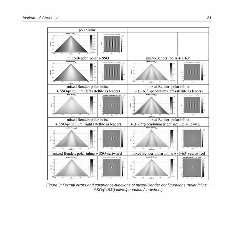
Afterwards, this algorithm was integrated into an open source genetic algorithm within the pythonprogramming environment using the (μ + λ)-evolution strategy. Figure 5 shows the flowchart ofsuch a genetic algorithm. The first step is usually the random creation of a population of individu-als. All members of this population are evaluated using the fitness function. A new generation ofindividuals is then created by applying two main strategies:
� mutation: one of the individuals is selected and one or more of its attributes are modifiedslightly.
� crossover: two or more of the selected individuals are recombined, with each of their childrenpossessing traits of all its parents.
Figure 5: Flowchart of the implemented genetic algorithm
34 GIS
The selection of the individuals that are used to form this new generation usually favors those withhigh fitness values, although it is desirable to keep some diversity in the population. This reducesthe risk of the population getting stuck in a local minimum of the solution space during evolution,and thus increases the chance of finding a globally optimal solution to the examined problem.
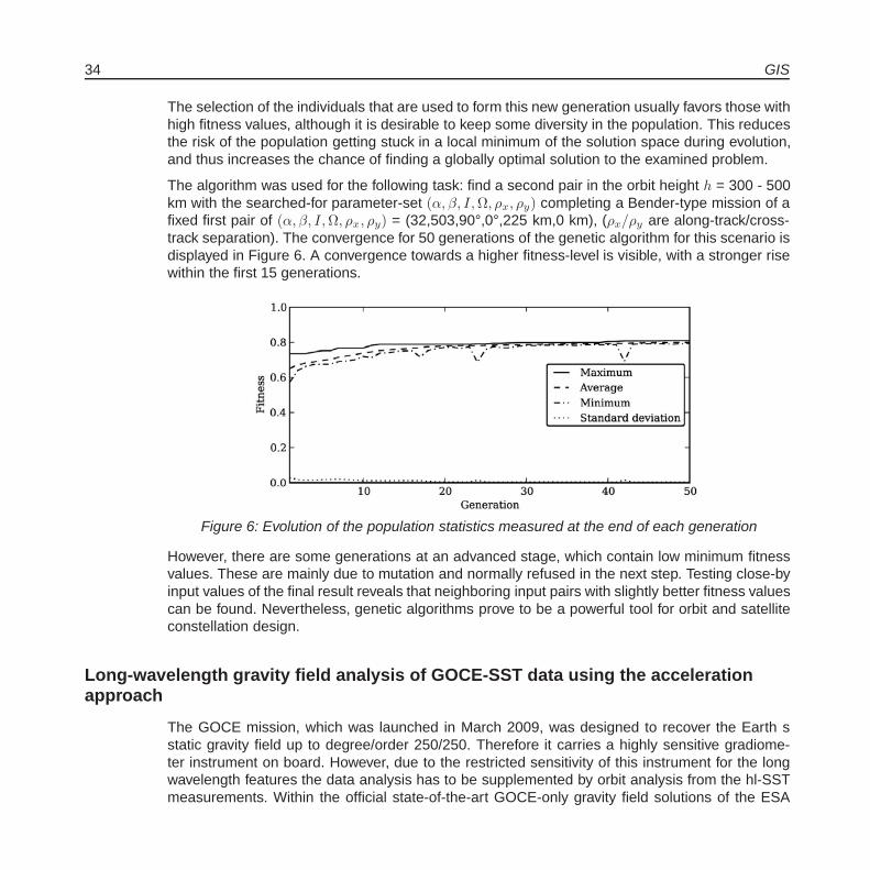
The algorithm was used for the following task: find a second pair in the orbit height h = 300 - 500km with the searched-for parameter-set (α, β, I,Ω, ρx, ρy) completing a Bender-type mission of afixed first pair of (α, β, I,Ω, ρx, ρy) = (32,503,90°,0°,225 km,0 km), (ρx/ρy are along-track/cross-track separation). The convergence for 50 generations of the genetic algorithm for this scenario isdisplayed in Figure 6. A convergence towards a higher fitness-level is visible, with a stronger risewithin the first 15 generations.
Figure 6: Evolution of the population statistics measured at the end of each generation
However, there are some generations at an advanced stage, which contain low minimum fitnessvalues. These are mainly due to mutation and normally refused in the next step. Testing close-byinput values of the final result reveals that neighboring input pairs with slightly better fitness valuescan be found. Nevertheless, genetic algorithms prove to be a powerful tool for orbit and satelliteconstellation design.
Long-wavelength gravity field analysis of GOCE-SST data using the accelerationapproach
The GOCE mission, which was launched in March 2009, was designed to recover the Earth sstatic gravity field up to degree/order 250/250. Therefore it carries a highly sensitive gradiome-ter instrument on board. However, due to the restricted sensitivity of this instrument for the longwavelength features the data analysis has to be supplemented by orbit analysis from the hl-SSTmeasurements. Within the official state-of-the-art GOCE-only gravity field solutions of the ESA
Institute of Geodesy 35
(European Space Agency) the orbit analysis is conducted by means of the energy balance ap-proach. As previous studies have shown, this approach is inferior by approximately a factor of√
3 by using only a 1D-observable compared to other hl-SST or orbit analysis methods. There-fore, within a joint activity of the Institute of Geodesy and the Space Research Institute (AustrianAcademy of Sciences, Graz) it is proposed to apply instead the acceleration approach, whichproved to be an efficient tool in CHAMP and GRACE data analysis. This approach evaluates theequation of motion directly. Therefore the kinematic orbits (official GOCE product, delivered bythe Astronomical Institute of the University of Bern, AIUB) have to be differentiated twice andcorrected for disturbing accelerations. Due to the drag-free system of GOCE the accelerometermeasurements are neglected.
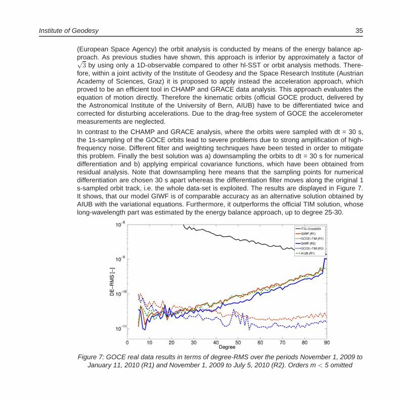
In contrast to the CHAMP and GRACE analysis, where the orbits were sampled with dt = 30 s,the 1s-sampling of the GOCE orbits lead to severe problems due to strong amplification of high-frequency noise. Different filter and weighting techniques have been tested in order to mitigatethis problem. Finally the best solution was a) downsampling the orbits to dt = 30 s for numericaldifferentiation and b) applying empirical covariance functions, which have been obtained fromresidual analysis. Note that downsampling here means that the sampling points for numericaldifferentiation are chosen 30 s apart whereas the differentiation filter moves along the original 1s-sampled orbit track, i.e. the whole data-set is exploited. The results are displayed in Figure 7.It shows, that our model GIWF is of comparable accuracy as an alternative solution obtained byAIUB with the variational equations. Furthermore, it outperforms the official TIM solution, whoselong-wavelength part was estimated by the energy balance approach, up to degree 25-30.
Figure 7: GOCE real data results in terms of degree-RMS over the periods November 1, 2009 toJanuary 11, 2010 (R1) and November 1, 2009 to July 5, 2010 (R2). Orders m < 5 omitted

36 GIS
GOCE Gravity Field Recovery - GOCE real data analysis by means of rotationalinvariants
The aim of Gravity field and steady-state Ocean Circulation Explorer (GOCE) Mission is to provideglobal and regional models of the Earth’s gravity field and of the geoid with high spatial resolutionand accuracy. Opposed to commonly applied analysis methods, the approach based on the rota-tional invariants of the gravitational tensor constitutes an independent alternative for gradiometerdata exploitation. In the framework of the REAL-GOCE project we have investigated the completeanalysis procedures in deriving the GOCE gravity field with rotational invariants (WP 120). Themain achievements are:
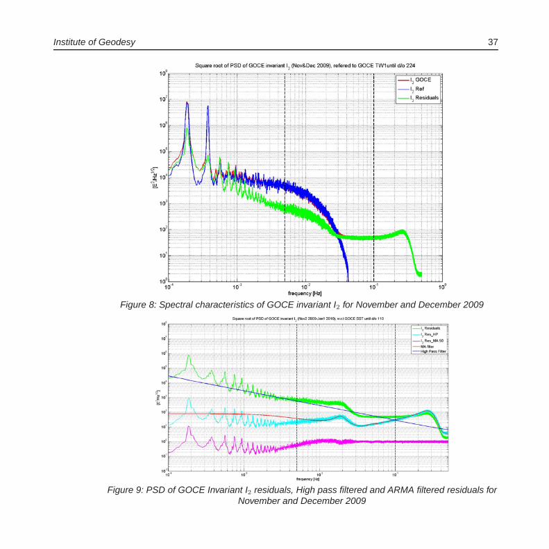
� after spectral analysis of GOCE invariant I2, see Figure 8, two key components of GOCE in-variant analysis, a moving-average (MA) filter with order 50 has been successfully estimatedand the filter cascade (high-pass and MA filters) has been implemented in GOCE invariantanalysis, see Figure 9;
� the polar gap problem is solved through the order-dependent Kaula regularization with aproper regularization parameter;
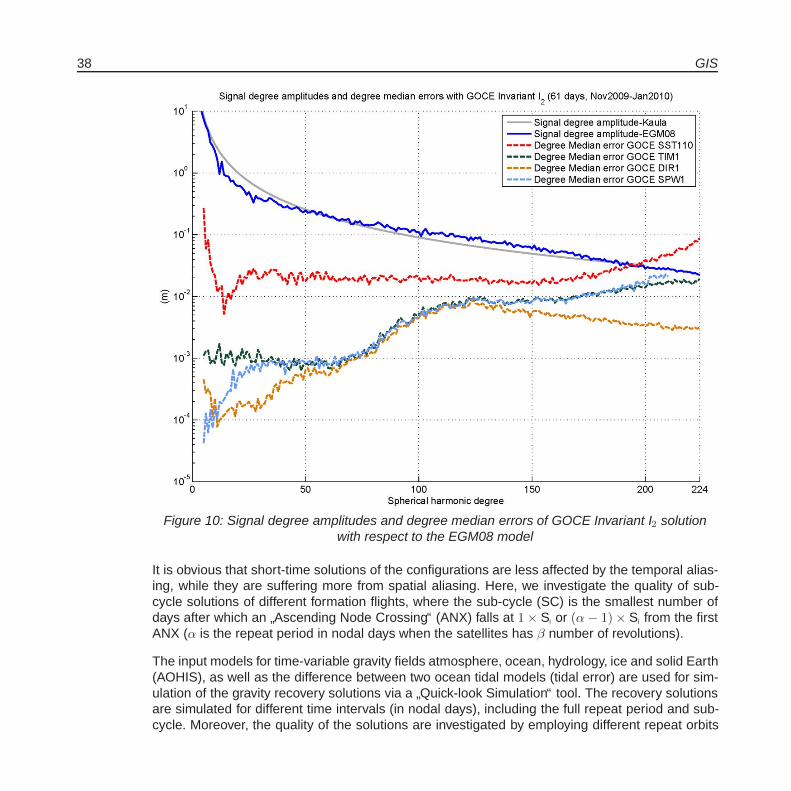
� based on two months of GOCE rotational invariants of gravitational tensor a high-resolutionglobal gravity field model until degree/order 224 has been derived by rotational invariants,where the GOCE SST solution until degree/order 110 (GIS) is used as reference model inthe linearization of invariants. The RMS degree variances and degree median errors with re-spect to the EGM08 model (see Figure 10) show that the invariant solution is consistent withthe three official GOCE solutions published in July 2010, especial for the middle and higherdegrees, which complementarily supports the published GOCE combination solutions.
Comparison of full-repeat and sub-cycle solutions in gravity recovery simulations offuture satellite missions
When using high quality sensors in future gravity missions, aliasing of the high frequency (shortperiod) geophysical signals to the lower frequency (longer period) signals is one of the most chal-lenging obstacles. Two sampling theorems mainly govern the space-time sampling of a satellite-mission: (i) Heisenberg uncertainty theorem which states that the product of spatial resolution andtime resolution is constant, and (ii) the Nyquist theorem, requires the number of satellite revolutionin a time interval equals or be larger than two times of the maximum spherical harmonic degreewhich is aimed to be detected and which, therefore, limits the spatial resolution of the solution.
Institute of Geodesy 37
Figure 8: Spectral characteristics of GOCE invariant I2 for November and December 2009
Figure 9: PSD of GOCE Invariant I2 residuals, High pass filtered and ARMA filtered residuals forNovember and December 2009
38 GIS
Figure 10: Signal degree amplitudes and degree median errors of GOCE Invariant I2 solutionwith respect to the EGM08 model
It is obvious that short-time solutions of the configurations are less affected by the temporal alias-ing, while they are suffering more from spatial aliasing. Here, we investigate the quality of sub-cycle solutions of different formation flights, where the sub-cycle (SC) is the smallest number ofdays after which an
”Ascending Node Crossing“ (ANX) falls at 1 × Si or (α − 1) × Si from the first
ANX (α is the repeat period in nodal days when the satellites has β number of revolutions).
The input models for time-variable gravity fields atmosphere, ocean, hydrology, ice and solid Earth(AOHIS), as well as the difference between two ocean tidal models (tidal error) are used for sim-ulation of the gravity recovery solutions via a
”Quick-look Simulation“ tool. The recovery solutions
are simulated for different time intervals (in nodal days), including the full repeat period and sub-cycle. Moreover, the quality of the solutions are investigated by employing different repeat orbits

Institute of Geodesy 39
of GRACE-like (inline) configurations, alternative formation flights like Pendulum and Cartwheeland two pairs of satellite missions of different inclinations.
The correlation between sub-cycle solutions (related to homogeneity of the satellite groundtrackson the Earth) of different repeat orbits and the quality of the recovery solutions are studied(Figure 11). For most of the repeat orbits, a significant drop for six days solution is seen. Thatis almost independent of the configuration (except for the drifting orbits with one day sub-cycles).The drop is approximately around the time interval when the number of revolutions is equal tomaximum spherical harmonic coefficients which is aimed to be detected (β ≥ Lmax). This is called
”Modified Colombo-Nyquist Law“.
The optimal repeat orbits of one pair satellite mission have been searched for short time recoverysolutions. By employing of two pairs satellite missions, the quality improvement, in both timeand space domains, is achieved. That means we can then have short time recovery solutionswith higher spatial resolution compared to the solution by just one pair satellite mission. Also, byemploying some post-processing analysis such as regularization and
”EOF+KS-Test“ white noise
filtering, we can achieve some more improvements, although some signals might be lost, as well(Figure 12).
Figure 11:”Accumulated Degree RMS“ of the errors of inline (GRACE-like) configurations for
different repeat orbits (solutions to maximum degree and order 90). The Y-axis is in logarithmicscale.

40 GIS
Figure 12:”Equivalent Water Height“ (EWH) maps of recovery solutions by one pair satellite
mission (left) and two pairs configuration (right), before (above) and after (below) white noisefiltering by
”EOF+KS-Test“ tool for 7 days recovery solutions as sub-cycle solutions.
Application of the differential gravimetry approach to the next generation ofintersatellite observations
The GRACE-mission proved to be one of the most important satellite missions in recent timesas it enabled the recovery of the static gravity field with unprecedented accuracy and, for thefirst time, the determination of temporal variations on a monthly (and shorter) basis. The key in-strument is the K-band ranging system which continuously measures the changes of the distancebetween the two GRACE satellites with an accuracy of a few micrometer. Thanks to the success ofthis mission, proposals have been made for the development of a GRACE-follow-on mission anda next-generation GRACE satellite system, respectively. Apart from options for a multi-satellitemission, the major improvement will be the replacement of the microwave based K-band rangingsystem by laser interferometry. The expected improvement in the accuracy is in the range of a fac-tor 10 to 1000. Two types of solution strategies exist for the determination of gravity field quantitiesfrom kinematic observations (range, range-rate and range-acceleration). The first type is based onnumerical integration. The most common ones are based on the classical integration of the varia-tional equations, a variant of it called the Celestial Mechanics Approach or the so-called short-arcmethod. The second type of solution strategies tries to make use of in-situ (pseudo)-observations.
Institute of Geodesy 41
The most typical ones are the energy balance approach, the relative acceleration approach or theline-of-sight gradiometry approach. From a theoretical point of view all approaches are in one wayor the other based on Newton’s equation of motion and thus all of them should be applicable tothe next generation of satellite missions as well. Practically, problems arise due to the necessity ofapproximations and linearizations, the accumulation of errors, the combination of highly-precisewith less precise quantities, e.g. K-band with GPS, and the incorporation of auxiliary measure-ments, e.g. accelerometer data. These problems are often circumvented by introducing referenceorbits, reducing the solution strategies to residual quantities, and by frequently solving for initialconditions and/or additional empirical or stochastic parameter. In the context of the next genera-tion of low-low satellite-to-satellite tracking systems, the question is whether these methods arestill sufficient to fully exploit the potential of the improved range observations.
Initial tests indicate that the solutions strategies needs refinement. Figure 13 shows the differ-ence degree RMS between input and solved-for spherical harmonic coefficients. The light bluecolor shows the current limitation due to the microwave intersatellite link. The blue line indicatesthe improvement of a laser system with respect to the microwave system. In the conservative as-sumption here, the improvement is approximately one order of magnitude. In the application of therelative acceleration approach, which has been used here, different types of observations need tobe combined, i.e. the less accurate GPS-observations contaminated the solution and limited theaccuracy of the solution. The limitation can be seen as the red line in Figure 13. About one orderof accuracy is lost. This limitation can be circumvented by introducing a reference orbit and reduc-ing the observations to residual quantities. Subject of the adjustment process are then correctionsto the initial gravity field which has been used to generate the reference orbit. With this methodsolutions on the accuracy level of a microwave system limited solution can be achieved. However,for the next generation of intersatellite observations, this approximation is not sufficient. Insteadhigher order terms need to be considered which demand an integration of the variational equa-tions. Figure 13 also shows such an attempt where a minor improvement is visible for degreeshigher than approximately 15. In this test, only changes to the spherical harmonic coefficientsare estimated but no corrections for errors in the initial conditions of the orbit of the two satelliteshave been applied. It is currently under investigation if these corrections can be estimated withsufficient accuracy as they are also based on GPS observations.

42 GIS
Figure 13: Difference degree RMS for different solutions of a simulation study
Institute of Geodesy 43
Theses
Doctoral Theses
(http://www.uni-stuttgart.de/gi/research/dissertations.en.html)
ANTONI M: Nichtlineare Optimierung regionaler Gravitationsfeldmodelle aus SST-Daten (Nonlin-ear optimization of regional gravity field models from SST data)
Diploma/Master Theses
(http://www.uni-stuttgart.de/gi/education/dipl/diploma theses.en.html)
ELLMER M: Optimization of the orbit parameters of future gravity missions using genetic algo-rithms (Optimierung der Orbitparameter zukunftiger Schweremissionen mithilfe genetis-cher Algorithmen)
LAGU AM: Evaluation of EGM2008 in the State of Baden-Wurttemberg using GPS and Leveling(Vergleich des EGM2008 in Baden-Wurttemberg durch Kombination von GPS und Nivelle-ment)
LEINSS B: Orbitverdichtung mittels Kalman-Filterung am Beispiel der Satellitenmission GRACE(Orbit densification by means of a Kalman-Filter applied to the satellite mission GRACE)
LI Y: Satellite Altimetry for hydrological purpose (Satellitenaltimetrie fur hydrologische Anwendun-gen)
NWOKE C: Monitoring the Uplift of the Land Surface using Gravimetry. A Case Study ofthe Geothermal Drill Site in the Town of Staufen, Breisgau (Uberwachung von Land-hebungen mittels Gravimetrie. Eine Fallstudie anlasslich der Geothermiebohrungen inStaufen/Breisgau)
SCHENK M: Development and Rating of Monitoring and Mitigation Methods for IonosphericThreats to Differential GNSS Applications for Precision Approach Guidance in Avia-tion (Entwicklung und Beurteilung von Methoden zur Uberwachung und Abschwachungionospharischer Bedrohungen fur prazise Landeanfluge in der Luftfahrt)
WANG L: GOCE gravity models and gravity gradient assessment (GOCE-Schwerefeldmodelleund Beurteilung der Gravitationsgradienten)

44 GIS
Publications(http://www.uni-stuttgart.de/gi/research/index.en.html)
Refereed Journal Publications
BAUR O AND N SNEEUW: Assessing Greenland ice mass loss by means of point-mass model-ing: a viable methodology. Journal of Geodesy 85 (2011) 607-615, DOI 10.1007/s00190-011-0463-1
GRAFAREND E: The transition from three-dimensional embedding to two-dimensional Euler-Lagrange deformation tensor of the second kind: variation of curvature measures. Pureand Applied Geophysics (2011), DOI 10.1007/s00024-011-0419-7
GRAFAREND E: Space gradiometry: tensor-valued ellipsoidal harmonics, the datum problem andapplication of the Lusternik-Schnirelmann category to construct a minimum atlas. Interna-tional Journal on Geomathematics 1 (2011) 145-166, DOI 10.1007/s13137-011-0013-2
GRAFAREND E AND W KUHNEL: A minimal atlas for the rotation group SO(3). InternationalJournal on Geomathematics 2 (2011) 113-122, DOI 10.1007/s13137-011-0018-x
KELLER W AND J HAJKOVA: Representation of planar integral-transformations by 4-D waveletdecomposition. Journal of Geodesy 85 (2011) 341-356
LIN Y, S ZHANG, J CAI AND N SNEEUW: Application of wavelet support vector regression onSAR data de-noising. Journal of Systems Engineering and Electronics 22 (2011) 579-586
TOURIAN M, J RIEGGER, N SNEEUW AND B DEVARAJU: Outlier identification and correctionfor GRACE aggregated data. Studia Geophysica et Geodaetica 55 (2011) 627-640, DOI10.1007/s11200-009-9007-z
ZOU X, J CAI, N SNEEUW AND J Li: Numerical study on the mixed model in the GOCE polargap problem. Geo-spatial Information Science 14 (2011) 216-222, DOI 10.1007/s11806-011-0532-x
Other Refereed Contributions
GRAFAREND E: Spacetime gradiometry: tensor-valued ellipsoidal harmonics, the datum problemand an application of the Lusternik-Schnirelmann Category to construct a minimum atlas.In: Contadakis ME et al (Eds., 2010): The apple of knowledge. In honor of Prof. em. D.N.Arabelos, pp. 121-145, ZHTH, Thessaloniki 2010
KELLER W, M KUHN AND WE FEATHERSTONE: A set of analytical formulae to model deglacia-tion. - Induced polar wander. In: Kenyon S, MC Pacino and U Marti (Eds.): Geodesy forthe Planet Earth. Proceedings of the 2009 IAG Symposium, Buenos Aires, pp 527-537,Springer Berlin Heidelberg, 2011
ROTH M, O BAUR AND W KELLER: Tailored usage of the NEC SX-8 and SX-9 systems in satellitegeodesy. In: Nagel WE, DB Kroner, MM Resch (Eds.): High Performance Computing inScience and Engineering ’10, Springer Berlin Heidelberg, pp. 561-572
Institute of Geodesy 45
Non-refereed Contributions
ANSELMI A, S CESARE, P VISSER, T VAN DAM, N SNEEUW, T GRUBER, B ALTES, BCHRISTOPHE, F COSSU, PG DITMAR, M MURBOCK, M PARISCH, M RENARD, TREUBELT, G SECHI AND JG TEXIEIRA DA ENCARNACAO: Assessment of a next gen-eration gravity mission to monitor the variations of Earth’s gravity field. ESA Contract No.22643/09/NL/AF, Executive Summary, Thales Alenia Space report SD-RP-AI-0721, March2011
REUBELT T, N SNEEUW AND S IRAN POUR: Quick-look gravity field analysis of formation sce-narios selection. In: Geotechnologien, Science Report No. 17, pp 126-133. Statusseminar
”Observation of the System Earth from Space“, Bonn (4.10.)
VAN DER WAL W, L WANG, P VISSER, N SNEEUW AND B VERMEERSEN: Evaluating GOCEdata near a mid-ocean ridge and possible application to crustal structure in Scandinavia.In: Proceedings 4th GOCE User Workshop ESA SP-696, July 2011, ESA, Munich (31.3.-1.4.)
WEIGELT M, O BAUR, T REUBELT, N SNEEUW AND M ROTH: Long wavelength gravity fielddetermination from GOCE using the acceleration approach. In: Proceedings 4th GOCEUser Workshop ESA SP-696, July 2011, ESA, Munich (31.3.-1.4.)
Poster Presentations
ANTONI M, W KELLER AND M WEIGELT: Comparison of genetic algorithm and descend direc-tion algorithm for SST data. EGU General Assembly, Vienna, Austria (3.-8.4.)
BAUR O, M WEIGELT, T REUBELT AND N SNEEUW: Towards an optimal GOCE-only gravityfield solution: recovery of long-wavelength features via the acceleration approach. EGUGeneral Assembly, Vienna, Austria (3.-8.4.)
CAI J, N SNEEUW AND O BAUR: GOCE gravity field model derived from the rotational invariantsof the gravitational tensor. BMBF Geotechnologien Statusseminar
”Erfassung des Systems
Erde aus dem Weltraum IV“, Stuttgart (11.10.)
CAI J, N SNEEUW, Q YANG AND O BAUR: Stochastic modeling of GOCE invariants in real dataanalysis. IUGG, Melbourne, Australia (28.6.-7.7.)
CAI J, N SNEEUW, Q YANG AND O BAUR: Implementing a stochastic model for GOCE invariants.4th GOCE User Workshop, ESA, Munich (31.3.-1.4.)
HIRTH M, W FICHTER, T REUBELT, N SNEEUW AND S IRAN POUR: Performance aspects offuture gravity mission constellations. EGU General Assembly, Vienna, Austria (3.-8.4.)
IRAN POUR S, N SNEEUW AND T REUBELT: Quality assessment of sub-cycle vs. full repeatperiod solutions of future gravity field missions, BMBF Geotechnologien Statusseminar
”Erfassung des Systems Erde aus dem Weltraum IV“, Stuttgart (11.10.)

46 GIS
KELLER W: Representation of planar integral-transformations by 4D wavelet decomposition. EGUGeneral Assembly, Vienna, Austria (3.-8.4.)
REUBELT T, N SNEEUW AND S IRAN POUR: Are subcycle solutions meaningful for time variablegravity field analysis from future satellite missions? AGU Fall Meeting 2011, San Francisco,California, USA (5.-9.12.)
REUBELT T, N SNEEUW, S IRAN POUR, W FICHTER AND M HIRTH: Sensitivity analysis offuture satellite formations and configurations of them. EGU General Assembly, Vienna,Austria (3.-8.4.)
SCHLESINGER R, M ROTH, N SNEEUW AND C NWOKE: Schweresignal im GeothermiefallStaufen - Jahresanalyse. Geodatische Woche Nurnberg (27.-29.9.)
VISSER P, M MURBOCK, T VAN DAM, T REUBELT, A ANSELMI, L MASSOTTI, P DITMAR,JT DE ENCARNACAO, T GRUBER, N SNEEUW, S CESARE, F COSSU, M PARISCH,G SECHI AND M AGUIRRE: Scientific assessment of a next generation gravity mission.EGU General Assembly, Vienna, Austria (3.-8.4.)
WANG L, W VAN DER WAL AND N SNEEUW: GOCE gravity models compared to EGM2008,GRACE and ship gravity measurements. EGU General Assembly, Vienna, Austria (3.-8.4.)
WEIGELT M, O BAUR, T REUBELT, N SNEEUW AND M ROTH: Long wavelength gravity fielddetermination from GOCE using the acceleration approach. 4th GOCE User Workshop,ESA, Munich (31.3.-1.4.)
ZHANG S, N SNEEUW, J CAI AND J LI: Zero-difference ambiguity fixing for PPP and preciseorbit determination. Geodatische Woche Nurnberg (27.-29.9.)
ZHAO W AND N SNEEUW: Local gravity field modeling by gradiometry. Geodatische WocheNurnberg (27.-29.9.)
Conference Presentations
BAUR O AND N SNEEUW: Assessing Greenland ice mass loss by means of point-mass model-ing: a viable methodology. EGU General Assembly, Vienna, Austria (3.-8.4.)
BAUR O AND N SNEEUW: Are genetic algorithms a universal parameter estimation tool ingeodesy? QuGOMS - The 1st International Workshop on the Quality of Geodetic Obser-vation and Monitoring Systems, Munich (13.-15.4.)
CAI J: Biased and unbiased estimations in geodetic data analyses. QuGOMS - The 1st Interna-tional Workshop on the Quality of Geodetic Observation and Monitoring Systems, Munich(13.-15.4.)
CAI J: Revisiting the search criteria for solving the mixed integer-real valued adjustment problemwith GNSS carrier phase observations. The 2nd China Satellite Navigation Conference(CSNC 2011), Shanghai, China (18.-20.5.)
Institute of Geodesy 47
CAI J, N SNEEUW, Q YANG AND O BAUR: GOCE gravity field model derived from rotationalinvariants. Geodatische Woche Nurnberg (27.-29.9.)
ELSAKA B, JC RAIMONDO, T REUBELT, S IRAN POUR, J KUSCHE, F FLECHTNER AND NSNEEUW: Full-Scale mission simulations. BMBF Geotechnologien Statusseminar
”Erfas-
sung des Systems Erde aus dem Weltraum IV“, Stuttgart (11.10.)
HIRTH M, W FICHTER, B SHEARD, G HEINZEL, T REUBELT AND N SNEEUW: Control systemdesign issues of future gravity missions. GNC 2011 - 8th International ESA Conference onGuidance and Navigation Control Systems. Karlovy Vary, Czech Republic (5.-10.6.)
IRAN POUR S, N SNEEUW, M WEIGELT AND T REUBELT: Assessment of the aliasing effectof white noise on different solutions in gravity recovery simulations of a GRACE-like mis-sion. IUGG General Assembly - Earth on the Edge: Science for a Sustainable Planet,Melbourne, Australia (28.6.-7.7.)
IRAN POUR S, N SNEEUW, T REUBELT AND M WEIGELT: Comparison of full-repeat and sub-cycle solutions in gravity recovery simulations of a GRACE-like mission. EGU GeneralAssembly, Vienna, Austria (3.-8.4.)
IRAN POUR S, N SNEEUW, T REUBELT AND M WEIGELT: Quality assessment of simulationsof future gravity field missions for hydrological purposes. Geodatische Woche Nurnberg(27.-29.9.)
KELLER W: Umordnung großer, schwach besetzter Normalgleichungsmatrizen mithilfe graphen-theoretischer und genetischer Algorithmen. Geodatische Woche Nurnberg (27.-29.9.)
KELLER W AND J HAJKOVA: Representation of planar integral-transformations by 4-D waveletdecomposition. EGU General Assembly, Vienna, Austria (3.-8.4.)
MOGHTASED-AZAR K, E GRAFAREND, F TAVAKOLI AND HZ NANKALI: Estimated PrincipalComponents of Deformation Tensors Derived from GPS Measurements under Assumptionof Both Independent and Correlated Tensor Observations (Case Study: Zagros Mountains,Iran). Joint International Symposium on Deformation Monitoring 2011, Hong Kong, China(2.-4.11.)
MURBOCK M, R PAIL, T GRUBER, T REUBELT, N SNEEUW, W FICHTER AND J MULLER:Concepts for future gravity satellite missions. Fragile Earth, Geological Processes fromGlobal to Local Scales, Associated Hazards and Resources. International Conference,Munich (4.-7.9.)
ROESE-KOERNER L, B DEVARAJU, WD SCHUH AND N SNEEUW: Describing the quality of in-equality constrained estimates. QuGOMS - The 1st International Workshop on the Qualityof Geodetic Observation and Monitoring Systems, Munich (13.-15.4.)
SCHALL J, O BAUR, JM BROCKMANN, J CAI, A EICKER, B KARGOLL, I KRASBUTTER, JKUSCHE, T MAYER-GURR, W-D SCHUH, A SHABANLOUI AND N SNEEUW: REal data

48 GIS
AnaLysis GOCE - Gravity field determination from GOCE. BMBF Geotechnologien Sta-tusseminar
”Erfassung des Systems Erde aus dem Weltraum IV“, Stuttgart (11.10.)
SNEEUW N: Spaceborne gravimetry: a novel tool for continental-scale storage change monitor-ing. EGU General Assembly, Vienna, Austria (3.-8.4.)
SNEEUW N, M WEIGELT AND X XU: Sampling the Earth with Satellites in Near-polar Orbit. IUGGGeneral Assembly - Earth on the Edge: Science for a Sustainable Planet, Melbourne,Australia (28.6.-7.7.)
TOURIAN M, J RIEGGER AND N SNEEUW: Long-range spatial correlations in GRACE products:a matter of S2-tidal aliasing? EGU General Assembly, Vienna, Austria (3.-8.4.)
TOURIAN M, J RIEGGER, N SNEEUW AND B DEVARAJU: Analysis of GRACE uncertaintiesby hydrological and hydrometeorological observations. QuGOMS - The 1st InternationalWorkshop on the Quality of Geodetic Observation and Monitoring Systems, Munich (13.-15.4.)
VISSER P, P DITMAR, J ENCARNACAO, M MURBOCK, T GRUBER, T VAN DAM, N SNEEUW,T. REUBELT, A ANSELMI, S CESARE, F COSSU, M PARISCH, G SECHI, L MASSOTTIAND M AGUIRRE: Scientific assessment of a next generation gravity mission. AGU FallMeeting 2011, San Francisco, California, USA (5.-9.12.)
WEIGELT M AND W KELLER: GRACE Gravity Field Solutions Using the Differential GravimetryApproach. IUGG General Assembly - Earth on the Edge: Science for a Sustainable Planet,Melbourne, Australia (28.6.-7.7.)
WEIGELT M, A JAGGI, L PRANGE, W KELLER AND N SNEEUW: Towards the time-variablegravity field from CHAMP. IUGG General Assembly - Earth on the Edge: Science for aSustainable Planet, Melbourne, Australia (28.6.-7.7.)
Books
GRAFAREND E AND J AWANGE: Linear and Nonlinear Models: Fixed Effects, Random Effectsand Total Least Squares. 600 pages, Springer, Berlin, Heidelberg, New York 2011
Guest Lectures and Lectures on special occasions
MARTI, U (Bundesamt fur Landestopografie, swisstopo, Wabern, Switzerland): Geodetic Worksfor the Gotthard Base Tunnel (8.6.)
ROESE-KOERNER, L (Institut fur Geodasie und Geoinformation, Theoretische Geodasie, Uni-versitat Bonn): Inequalities in Geodesy-toys or useful tools? (24.2.)
VOLTER, U (intermetric Gesellschaft fur Ingenieurmessung und raumbezogene Informationssys-teme mbH, Stuttgart): Anmerkungen zu den aktuellen Vermessungsarbeiten fur den Ein-bau der festen Fahrbahn im Gotthard Basis Tunnel (13.1.)
Institute of Geodesy 49
Lectures at other universities
CAI JBiased and unbiased estimations in geodetic data analyses. Wuhan University, Wuhan,China (6.1.)Advanced Satellite Positioning Data Proceeding. Central South University, Changsha,China (24.5.)Modern Geodetic Deformation Analysis. Central South University, Changsha, China (24.5.)GOCE data analysis based on rotational invariant . Wuhan University, Wuhan, China (5.9.)GOCE-only high-resolution gravity field model based on rotational invariant methodology.Wuhan University, Wuhan, China (28.12.)
GRAFAREND EThe Perspective 4 Point (P4P) Problem as well as the Twin Perspective 4 Point (TP4P)Problem - 3d resection and 3d intersection - by Moebius barycentric coordinates: appli-cation to Geodetic Positioning, Photogrammetry, Machine Vision, Robotics and ComputerVision, Remote Sensing. Geodetic Institute, Masala/Helsinki, Finland (19.8.)Von A. Einstein uber H. Weyl und E. Cartan zur Quantengravitation, Leibniz Sozietat derWissenschaften, Berlin (13.10.)
SNEEUW NGeodatische Raumverfahren fur die Hydrologie, Geodetic Colloquium, Universitat Bonn(20.10.)Hydrogeodesy, ITC, WRS Colloquium, University of Twente, Enschede, The Netherlands(30.11.)
Research Stays
CAI J: School of Geodesy and Geomatics, Wuhan University, China (1.-16.1.)
KELLER W: Landwirtschaftliche Universitat Wroclaw, Poland (26.8.-10.9.)
Lecture Notes
(http://www.uni-stuttgart.de/gi/education/dipl/lecturenotes.en.html,http://www.uni-stuttgart.de/gi/education/BSC/lecturenotes.en.html,http://www.uni-stuttgart.de/gi/geoengine/lecturenotes.html)
GRAFAREND E AND F KRUMMKartenprojektionen (Map Projections), 238 pages
HAUG GGrundstucksbewertung I (Real Estate/Property Valuation I), 32 pagesGrundstucksbewertung II (Real Estate/Property Valuation II), 11 pages

50 GIS
KELLER WDynamic Satellite Geodesy, 90 pagesFoundations of Satellite Geodesy, 51 pagesObservation Techniques in Satellite Geodesy, 50 pages
KRUMM F AND SNEEUW NAdjustment Theory, 141 pages
KRUMM FAdjustment Theory, 128 pagesMap Projections and Geodetic Coordinate Systems, 165 pagesMathematical Geodesy, 153 pagesReference Systems, 157 pages
SCHONHERR HAmtliches Vermessungswesen und Liegenschaftskataster (Official Surveying and Real Es-tate Regulation), 52 pages
SNEEUW NAnalytic Orbit Computation of Artificial Satellites / Dynamic Satellite Geodesy, 90 pagesHistory of Geodesy, 38 pagesGeodesy and Geodynamics, 68 pagesGeodesy and Geoinformatics, 31 pagesPhysical Geodesy (Measurement Techniques of Physical Geodesy, Modeling and DataAnalysis in the Field of Physical Geodesy), 137 pages
WOLF DContinuum Mechanics in Geophysics and Geodesy: Fundamental Principles, 100 pages
Participation in Conferences, Meetings and Workshops
CAI JBMBF Geotechnologien Statusseminar 2011,
”Erfassung des Systems Erde aus dem Wel-
traum III“, Stuttgart, Germany (11.10.)DFG SPP1257 Summer School, Mayschoss (12.-16.9.)Geodetic Week, Nurnberg, Germany (26.-29.9.)GOCE User Workshop, Munchen, Germany (31.3.-1.4.)REAL GOCE Project Meeting, Stuttgart (10.10.)REAL GOCE Project Meeting, Munchen (30.3.)The 1st International Workshop on the Quality of Geodetic Observation and MonitoringSyst - QuGOMS, Munchen, Germany (13.-15.4.)
DEVARAJU BIUGG General Assembly, Melbourne, Australia (28.6.-7.7.)

Institute of Geodesy 51
IRAN POUR SBMBF Geotechnologien Statusseminar 2011,
”Erfassung des Systems Erde aus dem Wel-
traum III“, Stuttgart, Germany (11.10.)Project meeting 4 of
”Zukunftskonzepte fur Schwerefeld-Satellitenmissionen“ (Geotech-
nologies - Observation of the System Earth from Space III), Menlo Systems GmbH, Mar-tinsried, Munchen (17.-18.1.)Project meeting 5 of
”Zukunftskonzepte fur Schwerefeld-Satellitenmissionen“ (Geotech-
nologies - Observation of the System Earth from Space III), IBZ, Stuttgart University,Stuttgart (12.10.)
REUBELT T
”Full-Scale-Meeting“ of
”Zukunftskonzepte fur Schwerefeld-Satellitenmissionen“ (Geotech-
nologies - Observation of the System Earth from Space III), IAPG, Munchen, Germany(12.5.)AGU Fall Meeting 2011, San Francisco, California, USA (5.-9.12.)BMBF Geotechnologien Statusseminar 2011,
”Erfassung des Systems Erde aus dem Wel-
traum III“, Stuttgart, Germany (11.10.)EGU General Assembly, Vienna, Austria (3.-8.4.)Project meeting 4 of
”Zukunftskonzepte fur Schwerefeld-Satellitenmissionen“ (Geotech-
nologies - Observation of the System Earth from Space III), Menlo Systems GmbH, Mar-tinsried, Munchen (17.-18.1.)Project meeting 5 of
”Zukunftskonzepte fur Schwerefeld-Satellitenmissionen“ (Geotech-
nologies - Observation of the System Earth from Space III), IBZ, Stuttgart University,Stuttgart (12.10.)
ROTH MGeodetic Week, Nurnberg, Germany (26.-29.9.)The 14th Results and Review Workshop, HLRS Stuttgart (4.-5.10.)CRAY XE6 Optimization Workshop, HLRS Stuttgart (2.-4.11.)
SCHLESINGER R:Geodetic Week, Nurnberg, Germany (26.-29.9.)
SNEEUW NBMBF Geotechnologien Statusseminar 2011,
”Erfassung des Systems Erde aus dem Wel-
traum III“, Stuttgart, Germany (11.10.)European Geosciences Union (EGU), General Assembly 2010, Vienna, Austria (3.-8.4.)Geodetic Week, Nurnberg, Germany (26.-29.9.)GOCE User Workshop, Munchen, Germany (31.3.-1.4.)IUGG General Assembly, Melbourne, Australia (28.6.-7.7.)The 1st International Workshop on the Quality of Geodetic Observation and MonitoringSyst - QuGOMS, Munchen, Germany (13.-15.4.)

52 GIS
TOURIAN MDFG-SPP1257 Symposium, Review Meeting, Potsdam (12.-14.10.)DFG-SPP1257 Workshop
”Mass transport and mass distribution in system Earth“, Dip-
perz/Fulda (22.-24.2.)
WEIGELT MGOCE User Workshop, Munchen, Germany (31.3.-1.4.)IUGG General Assembly, Melbourne, Australia (28.6.-7.7.)
University Service
GRAFAREND EMember Faculty of Aerospace Engineering and GeodesyMember Faculty of Civil- and Environmental EngineeringMember Faculty of Mathematics and Physics
ROTH MChairman of the PR-Commission of the study course Geodesy & Geoinformatics
SNEEUW NAssociate Dean (Academic) Geodasie & Geoinformatik and GEOENGINE, StuttgartMember China Commission, International Affairs (IA)Stand-by Member Senate Committee for Structural Development, StuttgartVice-Chair Examining Board of the Faculty of Aerospace Engineering and Geodesy,StuttgartMember Search Committee Differentialgeometrie
Professional Service (National)
GRAFAREND EEmeritus Member German Geodetic Commission (DGK)
SNEEUW NFull Member German Geodetic Commission (DGK)Chair DGK section
”Erdmessung“
Member Scientific Board of DGKMember Scientific Advisory Committee of DGFIChair AK7 (Working Group 7),
”Experimentelle, Angewandte und Theoretische Geodasie“,
within DVW (Gesellschaft fur Geodasie, GeoInformation und LandManagement)

Institute of Geodesy 53
Professional Service (International)
CAI JLuojia Professor at School of Geodesy and Geomatics, Wuhan University, China Memberof the Institute of Navigation (ION, USA)Member of European Geosciences Union (EGU)
GRAFAREND EElected Member of the Finnish Academy of Sciences and Letters, FinlandElected Member of the Hungarian Academy of Sciences, HungaryMember Royal Astronomical Society, Great BritainCorresponding Member Osterreichische Geodatische Kommission (OGK)Member Flat Earth SocietyElected Member Leibniz-Sozietat, BerlinFellow International Association of Geodesy (IAG)
SNEEUW NPrasident IAG InterCommission Committee on Theory (ICCT)Member Editorial board of Studia Geophysica et GeodaeticaMember Editorial board of Journal of GeodesyMember of IAG GGOS Working Group Satellite MissionsFellow International Association of Geodesy (IAG)
WEIGELT MChair of the study group JSG0.6: Applicability of current GRACE solution strategies to thenext generation of inter-satellite range observations, (Intercommission Committee on The-ory, IAG)Member of study group JSG0.3: Methodology of Regional Gravity Field Modeling (Inter-commission Committee on Theory, IAG)Member Inter-Commission Working Group (IC-WG2):
”Evaluation of Global Earth Gravity
Models“ (IAG)
Courses - Lecture/Lab/Seminar
Adjustment I, II (Krumm, Roth) 4/2/0Advanced Mathematics (Keller, Weigelt) 3/2/0Analytic Orbit Computation of Artificial Satellites (Sneeuw, Reubelt) 2/1/0Dynamic Satellite Geodesy (Keller) 1/1/0Foundations of Satellite Geodesy (Keller) 1/1/0Geodesy and Geoinformatics (Sneeuw) 1/1/0Geodetic Reference Systems (ICRS-ITRS) for Satellite Geodesy and Aerospace (Weigelt) 2/1/0Geodetic Seminar II (Krumm, Sneeuw) 0/0/2Gravity Field Modeling (Keller) 2/1/0

54 GIS
Integrated Field Work Geodesy and Geoinformatics (Keller, Sneeuw) 10 daysMap Projections and Geodetic Coordinate Systems (Krumm, Roth) 2/1/0Mathematical Geodesy (Krumm) 2/1/0Mathematical Geodesy (Krumm, Roth) 2/2/0Measurement Techniques of Physical Geodesy (Sneeuw, Reubelt) 2/1/0Modeling and Data Analysis in the Field of Physical Geodesy (Engels, Reubelt) 2/1/0Observation Techniques and Evaluation Procedures of Satellite Geodesy (Keller, Weigelt) 1/1/0Official Surveying and Real Estate Regulation (Schonherr) 2/0/0Orbit Determination and Analysis of Artificial Satellites (Keller, Reubelt) 2/1/0Physical Geodesy (Sneeuw, Reubelt) 2/1/0Real-Estate/Property Valuation I, II (Haug) 2/1/0Reference Systems (Krumm, Roth) 2/2/0Satellite Geodesy Observation Techniques (Weigelt) 1/1/0Satellite Geodesy (Keller) 2/1/0Statistical Inference (Krumm, Roth) 2/1/0

Institute of Navigation 55
Institute of NavigationBreitscheidstrasse 2, D-70174 Stuttgart,Tel.: +49 711 685 83400, Fax: +49 711 685 82755e-mail: [email protected]: http://www.nav.uni-stuttgart.de
Head of InstituteProf. Dr.-Ing. A. K l e u s b e r g
Deputy: Dr.-Ing. Aloysius W e h rSecretary: Helga M e h r b r o d tEmeritus: Prof. em. Dr.-Ing. Ph. H a r t l
StaffDipl.-Ing. Doris B e c k e r Navigation SystemsDipl.-Ing. Xu F a n g Navigation SystemsDipl.-Ing. Michael G a b Navigation SystemsDipl.-Geogr. Thomas G a u g e r GIS Modelling and MappingDipl.-Ing. Rene P a s t e r n a k Remote SensingDipl.-Ing. Bernhardt S c h a f e r Navigation SystemsDipl.-Ing. Wolfgang S c h o l l e r Education/Navigation SystemsM. Sc. Hendy S u h a n d r i Navigation SystemsDipl.-Ing. (FH) Martin T h o m a s Laser SystemsDr.-Ing. Aloysius W e h r Laser SystemsDipl.-Ing. Xue W e i Inertial NavigationDr. Ing. Franziska W i l d - P f e i f f e r Navigation Systems
EDP and NetworkingRegine S c h l o t h a n
Laboratory and Technical Shop (ZLW)Dr.-Ing. Aloysius W e h r (Head of ZLW)Technician Peter S e l i g - E d e rElectrician Sebastian S c h n e i d e rMechanician Master Michael P f e i f f e r
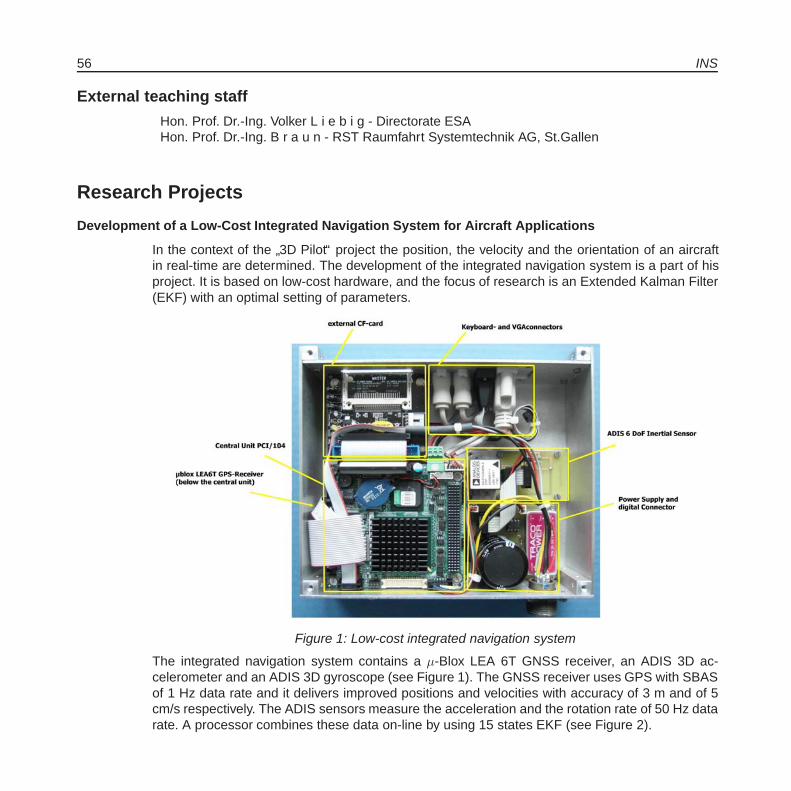
56 INS
External teaching staff
Hon. Prof. Dr.-Ing. Volker L i e b i g - Directorate ESAHon. Prof. Dr.-Ing. B r a u n - RST Raumfahrt Systemtechnik AG, St.Gallen
Research Projects
Development of a Low-Cost Integrated Navigation System for Aircraft Applications
In the context of the”3D Pilot“ project the position, the velocity and the orientation of an aircraft
in real-time are determined. The development of the integrated navigation system is a part of hisproject. It is based on low-cost hardware, and the focus of research is an Extended Kalman Filter(EKF) with an optimal setting of parameters.
Figure 1: Low-cost integrated navigation system
The integrated navigation system contains a μ-Blox LEA 6T GNSS receiver, an ADIS 3D ac-celerometer and an ADIS 3D gyroscope (see Figure 1). The GNSS receiver uses GPS with SBASof 1 Hz data rate and it delivers improved positions and velocities with accuracy of 3 m and of 5cm/s respectively. The ADIS sensors measure the acceleration and the rotation rate of 50 Hz datarate. A processor combines these data on-line by using 15 states EKF (see Figure 2).
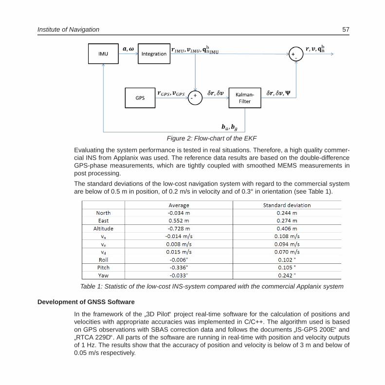
Institute of Navigation 57
Figure 2: Flow-chart of the EKF
Evaluating the system performance is tested in real situations. Therefore, a high quality commer-cial INS from Applanix was used. The reference data results are based on the double-differenceGPS-phase measurements, which are tightly coupled with smoothed MEMS measurements inpost processing.
The standard deviations of the low-cost navigation system with regard to the commercial systemare below of 0.5 m in position, of 0.2 m/s in velocity and of 0.3° in orientation (see Table 1).
Table 1: Statistic of the low-cost INS-system compared with the commercial Applanix system
Development of GNSS Software
In the framework of the”3D Pilot“ project real-time software for the calculation of positions and
velocities with appropriate accuracies was implemented in C/C++. The algorithm used is basedon GPS observations with SBAS correction data and follows the documents
”IS-GPS 200E“ and
”RTCA 229D“. All parts of the software are running in real-time with position and velocity outputs
of 1 Hz. The results show that the accuracy of position and velocity is below of 3 m and below of0.05 m/s respectively.
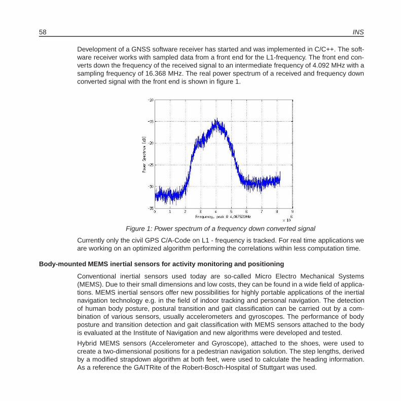
58 INS
Development of a GNSS software receiver has started and was implemented in C/C++. The soft-ware receiver works with sampled data from a front end for the L1-frequency. The front end con-verts down the frequency of the received signal to an intermediate frequency of 4.092 MHz with asampling frequency of 16.368 MHz. The real power spectrum of a received and frequency downconverted signal with the front end is shown in figure 1.
Figure 1: Power spectrum of a frequency down converted signal
Currently only the civil GPS C/A-Code on L1 - frequency is tracked. For real time applications weare working on an optimized algorithm performing the correlations within less computation time.
Body-mounted MEMS inertial sensors for activity monitoring and positioning
Conventional inertial sensors used today are so-called Micro Electro Mechanical Systems(MEMS). Due to their small dimensions and low costs, they can be found in a wide field of applica-tions. MEMS inertial sensors offer new possibilities for highly portable applications of the inertialnavigation technology e.g. in the field of indoor tracking and personal navigation. The detectionof human body posture, postural transition and gait classification can be carried out by a com-bination of various sensors, usually accelerometers and gyroscopes. The performance of bodyposture and transition detection and gait classification with MEMS sensors attached to the bodyis evaluated at the Institute of Navigation and new algorithms were developed and tested.
Hybrid MEMS sensors (Accelerometer and Gyroscope), attached to the shoes, were used tocreate a two-dimensional positions for a pedestrian navigation solution. The step lengths, derivedby a modified strapdown algorithm at both feet, were used to calculate the heading information.As a reference the GAITRite of the Robert-Bosch-Hospital of Stuttgart was used.
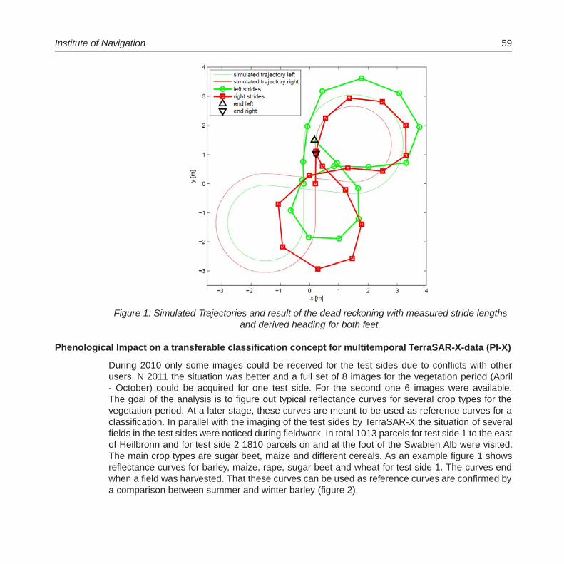
Institute of Navigation 59
Figure 1: Simulated Trajectories and result of the dead reckoning with measured stride lengthsand derived heading for both feet.
Phenological Impact on a transferable classification concept for multitemporal TerraSAR-X-data (PI-X)
During 2010 only some images could be received for the test sides due to conflicts with otherusers. N 2011 the situation was better and a full set of 8 images for the vegetation period (April- October) could be acquired for one test side. For the second one 6 images were available.The goal of the analysis is to figure out typical reflectance curves for several crop types for thevegetation period. At a later stage, these curves are meant to be used as reference curves for aclassification. In parallel with the imaging of the test sides by TerraSAR-X the situation of severalfields in the test sides were noticed during fieldwork. In total 1013 parcels for test side 1 to the eastof Heilbronn and for test side 2 1810 parcels on and at the foot of the Swabien Alb were visited.The main crop types are sugar beet, maize and different cereals. As an example figure 1 showsreflectance curves for barley, maize, rape, sugar beet and wheat for test side 1. The curves endwhen a field was harvested. That these curves can be used as reference curves are confirmed bya comparison between summer and winter barley (figure 2).
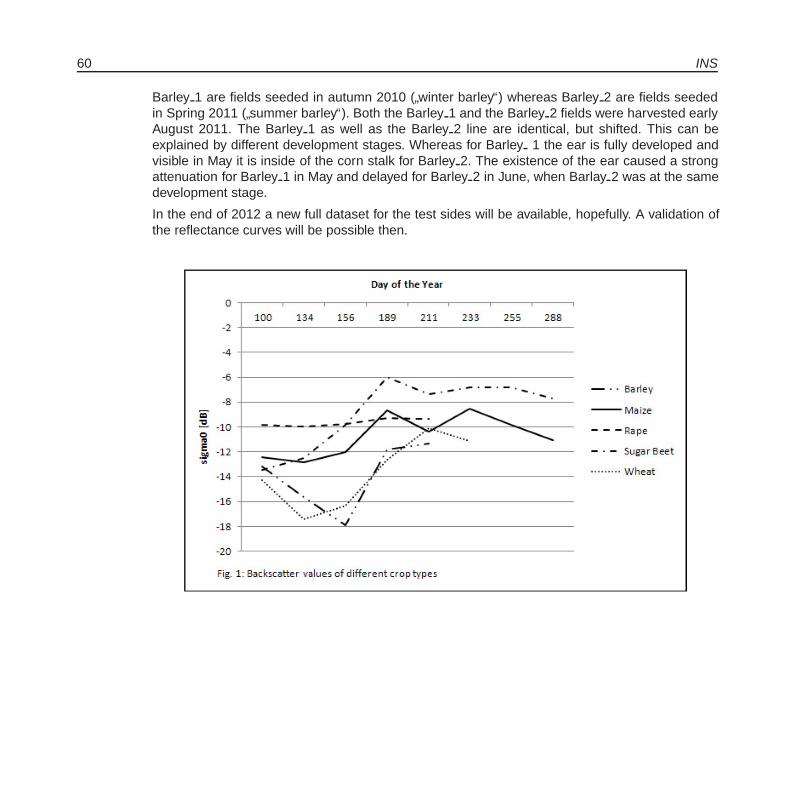
60 INS
Barley 1 are fields seeded in autumn 2010 (”winter barley“) whereas Barley 2 are fields seeded
in Spring 2011 (”summer barley“). Both the Barley 1 and the Barley 2 fields were harvested early
August 2011. The Barley 1 as well as the Barley 2 line are identical, but shifted. This can beexplained by different development stages. Whereas for Barley 1 the ear is fully developed andvisible in May it is inside of the corn stalk for Barley 2. The existence of the ear caused a strongattenuation for Barley 1 in May and delayed for Barley 2 in June, when Barlay 2 was at the samedevelopment stage.
In the end of 2012 a new full dataset for the test sides will be available, hopefully. A validation ofthe reflectance curves will be possible then.

Institute of Navigation 61
Publications and Presentations:
Schafer, B.; Wild-Pfeiffer, F.; Xue, W.; Becker, C.; Lindemann, U.: Applications of bodymountedMEMS inertial sensors. IUGG 2011, 28 June - 7 July 2011, Melbourne, Australia
Schafer, B.: Determination of heading information from gait cycle pattern using stride length es-timation with reduced IMUs on right and left foot, in:
”Proceedings of the 2011 Interna-
tional Conference on Indoor Positioning and Indoor Navigation (IPIN’2011) - short papers,posters and demos“, Moreira, Adriano J. C.; Meneses, Filipe M. L. (eds.). Guimaraes, Por-tugal; ISBN 978-972-8692-63-6
Schafer, B.; Ellmer, M.; Zechmann, H.: Kinematische Positionierung eines Rennwagens mit Low-Cost GPS - Aufbau des Systems und Validierung erster Ergebnisse. Geodatische Woche2011, 27-29 September 2011, Nurnberg
Reinhold, A., Xue, W., Wild-Pfeiffer, F., Pfeiffer, R.:”Untersuchung der Lage- und Orientierungsge-
nauigkeit von MEMS-Inertialsensoren hinsichtlich der Integration in einen handgefuhrten3D-Scanner“, Geodatische Woche 2011, 27.- 29.09.2011, Nurnberg.
Wild-Pfeiffer, F., Schafer, B.:”MEMS-Sensoren, auch fur die Geodasie“, ZfV, 136 (1/2011), S.30-
39.

62 INS
Wild-Pfeiffer, F.:”Grundlagen zur Erfassung korperlicher Aktivitat mittels MEMS-Sensoren“, Col-
loquium des Masterstudiengangs Sportwissenschaft: Gesundheitsforderung, 10.03.2011,Stuttgart.
Wild-Pfeiffer, F.:”Effects of topographic and isostatic masses in satellite gravity gradiometry“, Vor-
trag im Rahmen des Forschungsaufenthaltes am Institut fur Theoretische Geodasie, Slo-vak University of Technology, 31.08.2011, Bratislava.
Diploma ThesisFriederichs, T.: Entwicklung eines Algorithmus zur Bestimmung der Objektlage und Position im
dreidimensionalen Raum (Wild-Pfeiffer)
Master ThesisBartholomew Thiong´o Kuria: Differentiation of some important cultures in Baden-Wuerttemberg,
Germany using TerraSAR-X data
Study ThesisEnderle, Florian:
”Orientierung eines dreiachsigen MEMS Magnetfeld- und Beschleunigungssen-
sors“; Studienarbeit, Institut fur Navigation; Universitat Stuttgart; Juli 2011; (Schafer).
Reinhold, A.: Erstellung eines Konzepts zur Untersuchung der Lage- und Orientierungsge-nauigkeit von MEMS-Sensoren hinsichtlich der Integration in einen 3DInnenschuhscanner(Xue, Wild-Pfeiffer)
Dohrer, M.: Entwicklung von Ilias-Lernmaterialien im Bereich”Fernerkundung“ zur Forderung von
eigenmotiviertem Lernen (Wild-Pfeiffer)
Participation in Conferences, Meetings and Workshops:Wild-Pfeiffer, F.
Research Stay at the Department of Theoretical Geodesy, Slovak University of Technol-ogy, Bratislava (29.08. - 02.09.2011)Gyro Symposium, Karlsruhe, 20.-21.09.2011Geodetic Week, Nurnberg, 28.-29.09.2011
Schafer B.International Union of Geodesy and Geophysics (IUGG) General Assembly 2011, 28 June- 7 July 2011, Melbourne, AustraliaInternational Conference on Indoor Positioning and Indoor Navigation (IPIN) 2011, 21-23September 2011, Guimaraes, PortugalGeodatische Woche 2011, 27-29 September 2011, Nurnberg

Institute of Navigation 63
Activities in National and International Organizations
Alfred KleusbergFellow of the International Association of the GeodesyMember of the Institute of Navigation (U.S.)Member of the Royal Institute of NavigationMember of the German Institute of Navigation
Wild-Pfeiffer, F.Workshop der
”Frauen im DVW“, Kassel, 26.-27.02.2011
Meeting”Frauen im DVW“, Intergeo Nurnberg, 28.09.2011
Guest Lectures
Weidner, U. (Institute of Photogrammetry and Remote Sensing, Karlsruhe Institute of RemoteSensing):
”Hyperspectral Remote Sensing“, 08.06.2011.
Freiberger Jr., J. (Setor de Geodesia e Topografia, Departamento de Engenharia Rural, Universi-dade Federal de Santa Maria, RS, Brasil):
”The Brazilian GNSS reference network: stand
and perspectives“, 20.07.2011.
Saatkamp, E. D. (Setor de Geodesia e Topografia, Departamento de Engenharia Rural, Universi-dade Federal de Santa Maria, RS, Brasil):
”The RTCM SC-104 standard: decoding, data
transmission by RDS, and coding“, 20.07.2011.
Education (Lecture / Practice / Training / Seminar)
Navigation and Remote Sensing (Kleusberg, Schafer) 2/1/0/0Introduction of Geodesy and Geoinformatic (BSc) (Kleusberg, Schafer) 2/2/0/0Electronics and Electrical Engineering (Wehr, Fang) 2/1/0/0Satellite Measurement Engineering (Wehr, Fang) 2/1/0/0Aircraft Navigation (Scholler, Wehr) 2/0/0/0Parameter Estimation in Dynamic Systems (Kleusberg) 2/1/0/0Navigation I (Kleusberg, Xue) 2/2/0/0Inertial Navigation (Kleusberg, Xue) 2/2/0/0Remote Sensing I (Wild-Pfeiffer, Pasternak) 2/2/0/0Remote Sensing I (BSc) (Wild-Pfeiffer, Pasternak) 2/1/0/0Remote Sensing II (Wild-Pfeiffer, Pasternak) 1/1/0/0Satellite Programs in Remote Sensing, Communication and Navigation I (Liebig) 2/0/0/0Satellite Programs in Remote Sensing, Communication and Navigation II (Liebig) 2/0/0/0Radar Measurement Methods I (Braun) 2/0/0/0Radar Measurement Methods II (Braun) 2/1/0/0Navigation II (Becker) 2/2/0/0

64 INS
Integrated Positioning and Navigation (Kleusberg) 2/1/0/0Interplanetary Trajectories (Becker) 1/1/0/0Practical Course in Navigation (Scholler) 0/0/2/0Geodetic Seminar I, II (Fritsch, Sneeuw, Keller, Kleusberg, Mohlenbrink) 0/0/0/4Integrated Fieldwork (Schafer, Fang) (SS 2011)

Institute for Photogrammetry 65
Institute for PhotogrammetryGeschwister-Scholl-Str. 24D, D-70174 StuttgartTel.: +49 711 685 83386, Fax: +49 711 685 83297e-mail: [email protected]: http://www.ifp.uni-stuttgart.de
Head of InstituteDirector: Prof. Dr.-Ing. Dieter FritschDeputy: apl. Prof. Dr.-Ing. Norbert HaalaPersonal Assistant: Martina Kroma
Emeritus Professor: Prof. i.R. Dr. mult. Fritz Ackermann
Research Groups at the ifp:
Geoinformatics
Chair: Prof. Dr.-Ing. Dieter FritschDeputy: Dr.-Ing. Volker Walter GIS and Remote SensingDr.-Ing. Susanne Becker Point Cloud InterpretationDipl.-Ing. Yevgeniya Filippovska Data Quality
Photogrammetry and Computer Vision
Chair: Prof. Dr.-Ing. Dieter FritschDeputy: Dr.-Ing. Michael Cramer Digital Airborne SensorsM.Sc. Eng. Angela Budroni Indoor Model ReconstructionDipl.-Ing. Alessandro Cefalu Photogrammetric Calibration and Object RecognitionDipl.-Ing.(FH) Markus Englich Sensor LaboratoryDipl.-Ing. Alexander Fietz Indoor MappingM.Sc. Eng. Ali Mohammed Khosravani Indoor Modeling and PositioningM.Sc. Eng. Wassim Moussa Sensor FusionM.Sc. Eng. Mohammed Othman Image OrientationDipl.-Ing. Michael Peter Indoor PositioningDipl.-Ing. Carina Raizner Objective Stray Light MeasurementDipl.-Ing.(FH) Werner Schneider Digital Photogrammetry LaboratoryM.Sc. Eng. Rongfu Tang Bundle Block Adjustment ExtensionDipl.-Ing. Konrad Wenzel Dense Image Matching in Close Range Applications
66 ifp
Photogrammetric Image Processing
Chair: apl. Prof. Dr. Norbert HaalaDipl.-Ing. Mathias Rothermel Semi-Global Matching
External Teaching Staff
Dipl.-Ing. Stefan Dvorak, Amt fur Stadtentwicklung und Vermessung, ReutlingenDipl.-Ing. Sabine Urbanke, Landesvermessungsamt Baden-Wurttemberg
Research ProjectsGeoinformatics
Data Model for Hybrid 3D Geoinformation Systems
In the last years, substantial technological progress in managing 3D geospatial data could beobserved. New technologies for the collection of 3D data (in particular airborne and terrestriallaser scanner) as well as an increasing performance of CPUs and GPUs have made it possiblethat today 3D data can be collected for large areas and handled on standards PCs. However, thereis still a lack of appropriate tools for integrated data management and analysis solutions that cancope with the great diversity of 3D geodata. Thus, we deal with the development of a hybrid 3Dgeoinformation system which is able to combine and analyse heterogeneous 3D geodata in anefficient and consistent way.
The huge diversity of geodata becomes obvious when considering existing data models. While the2D world mainly distinguishes between raster and vector representations, much more modellingconcepts are in use for data of higher dimensions. Typical data models for 2.5D surfaces are gridsor TINs; 3D solids can be described by voxel and boundary representations (BRep) as well asby mathematical definitions like parametric instancing or half-space modelling. Constructive solidgeometry (CSG) and cell decomposition specify different modelling strategies for generating com-plex 3D objects through the combination of several basic 3D primitives, which can be representedin any of the aforementioned data models for solids. Beyond that, geodata can also be heteroge-neous with respect to its quality properties (e.g. accuracy, density, completeness). Considering allthese aspects, a meaningful and effective usage of geodata necessarily requires geoinformationsystems which are hybrid in the sense of data model, dimension and quality.
We developed a data model which is meant to provide an application-independent conceptualbasis for smart geoinformation systems. The data model is hybrid with respect to structural andgeometric aspects. Through targeted extensions of the widely accepted standard ISO 19107, our
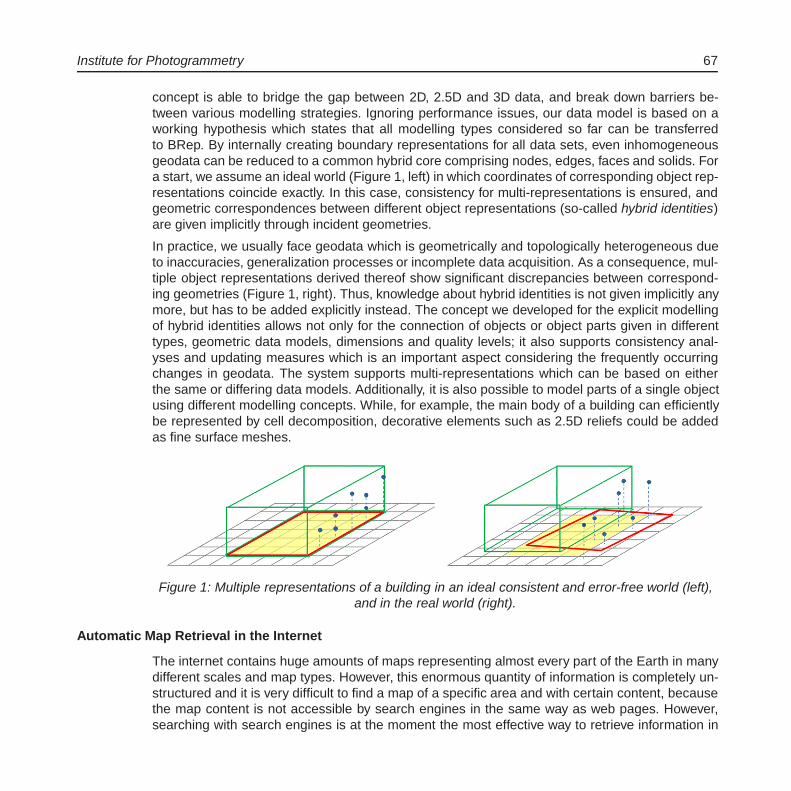
Institute for Photogrammetry 67
concept is able to bridge the gap between 2D, 2.5D and 3D data, and break down barriers be-tween various modelling strategies. Ignoring performance issues, our data model is based on aworking hypothesis which states that all modelling types considered so far can be transferredto BRep. By internally creating boundary representations for all data sets, even inhomogeneousgeodata can be reduced to a common hybrid core comprising nodes, edges, faces and solids. Fora start, we assume an ideal world (Figure 1, left) in which coordinates of corresponding object rep-resentations coincide exactly. In this case, consistency for multi-representations is ensured, andgeometric correspondences between different object representations (so-called hybrid identities)are given implicitly through incident geometries.
In practice, we usually face geodata which is geometrically and topologically heterogeneous dueto inaccuracies, generalization processes or incomplete data acquisition. As a consequence, mul-tiple object representations derived thereof show significant discrepancies between correspond-ing geometries (Figure 1, right). Thus, knowledge about hybrid identities is not given implicitly anymore, but has to be added explicitly instead. The concept we developed for the explicit modellingof hybrid identities allows not only for the connection of objects or object parts given in differenttypes, geometric data models, dimensions and quality levels; it also supports consistency anal-yses and updating measures which is an important aspect considering the frequently occurringchanges in geodata. The system supports multi-representations which can be based on eitherthe same or differing data models. Additionally, it is also possible to model parts of a single objectusing different modelling concepts. While, for example, the main body of a building can efficientlybe represented by cell decomposition, decorative elements such as 2.5D reliefs could be addedas fine surface meshes.
Figure 1: Multiple representations of a building in an ideal consistent and error-free world (left),and in the real world (right).
Automatic Map Retrieval in the Internet
The internet contains huge amounts of maps representing almost every part of the Earth in manydifferent scales and map types. However, this enormous quantity of information is completely un-structured and it is very difficult to find a map of a specific area and with certain content, becausethe map content is not accessible by search engines in the same way as web pages. However,searching with search engines is at the moment the most effective way to retrieve information in
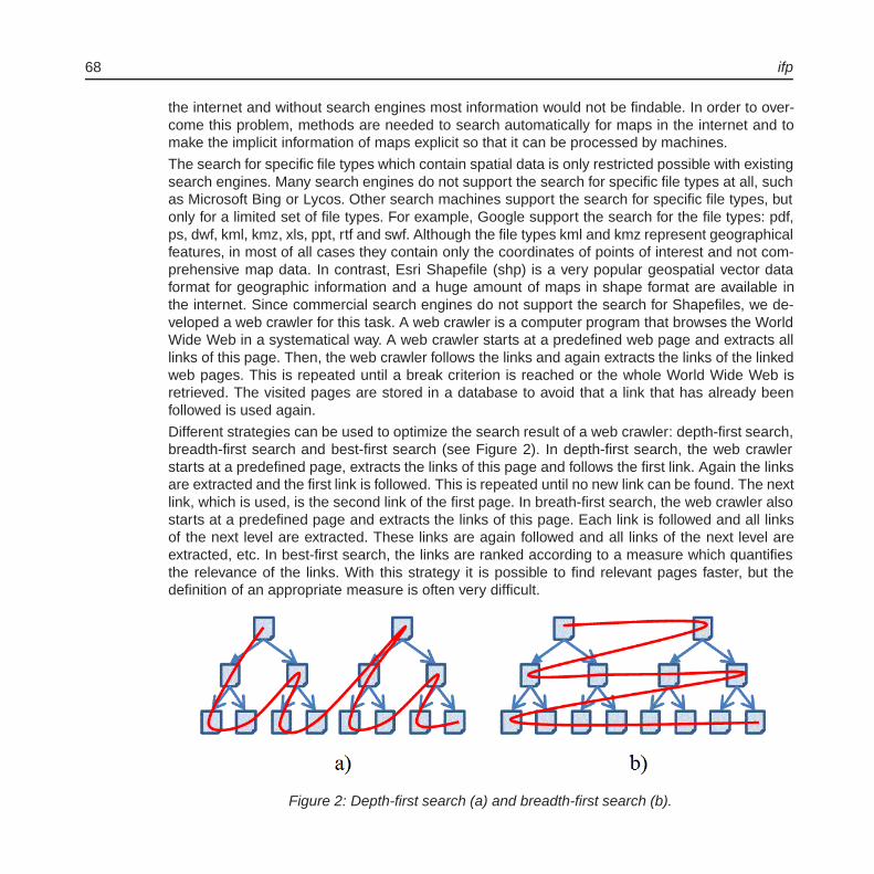
68 ifp
the internet and without search engines most information would not be findable. In order to over-come this problem, methods are needed to search automatically for maps in the internet and tomake the implicit information of maps explicit so that it can be processed by machines.
The search for specific file types which contain spatial data is only restricted possible with existingsearch engines. Many search engines do not support the search for specific file types at all, suchas Microsoft Bing or Lycos. Other search machines support the search for specific file types, butonly for a limited set of file types. For example, Google support the search for the file types: pdf,ps, dwf, kml, kmz, xls, ppt, rtf and swf. Although the file types kml and kmz represent geographicalfeatures, in most of all cases they contain only the coordinates of points of interest and not com-prehensive map data. In contrast, Esri Shapefile (shp) is a very popular geospatial vector dataformat for geographic information and a huge amount of maps in shape format are available inthe internet. Since commercial search engines do not support the search for Shapefiles, we de-veloped a web crawler for this task. A web crawler is a computer program that browses the WorldWide Web in a systematical way. A web crawler starts at a predefined web page and extracts alllinks of this page. Then, the web crawler follows the links and again extracts the links of the linkedweb pages. This is repeated until a break criterion is reached or the whole World Wide Web isretrieved. The visited pages are stored in a database to avoid that a link that has already beenfollowed is used again.
Different strategies can be used to optimize the search result of a web crawler: depth-first search,breadth-first search and best-first search (see Figure 2). In depth-first search, the web crawlerstarts at a predefined page, extracts the links of this page and follows the first link. Again the linksare extracted and the first link is followed. This is repeated until no new link can be found. The nextlink, which is used, is the second link of the first page. In breath-first search, the web crawler alsostarts at a predefined page and extracts the links of this page. Each link is followed and all linksof the next level are extracted. These links are again followed and all links of the next level areextracted, etc. In best-first search, the links are ranked according to a measure which quantifiesthe relevance of the links. With this strategy it is possible to find relevant pages faster, but thedefinition of an appropriate measure is often very difficult.
Figure 2: Depth-first search (a) and breadth-first search (b).
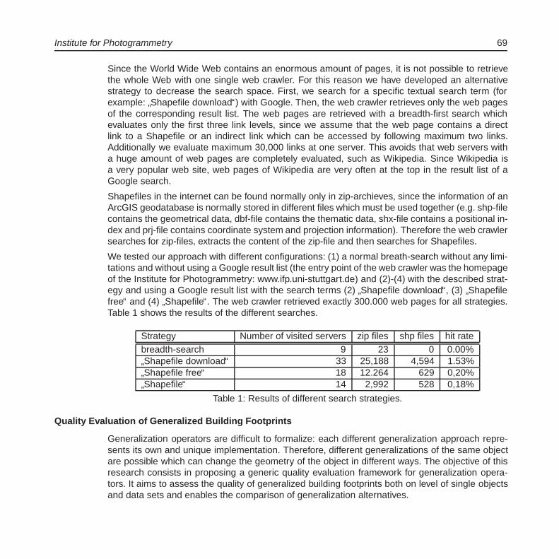
Institute for Photogrammetry 69
Since the World Wide Web contains an enormous amount of pages, it is not possible to retrievethe whole Web with one single web crawler. For this reason we have developed an alternativestrategy to decrease the search space. First, we search for a specific textual search term (forexample:
”Shapefile download“) with Google. Then, the web crawler retrieves only the web pages
of the corresponding result list. The web pages are retrieved with a breadth-first search whichevaluates only the first three link levels, since we assume that the web page contains a directlink to a Shapefile or an indirect link which can be accessed by following maximum two links.Additionally we evaluate maximum 30,000 links at one server. This avoids that web servers witha huge amount of web pages are completely evaluated, such as Wikipedia. Since Wikipedia isa very popular web site, web pages of Wikipedia are very often at the top in the result list of aGoogle search.
Shapefiles in the internet can be found normally only in zip-archieves, since the information of anArcGIS geodatabase is normally stored in different files which must be used together (e.g. shp-filecontains the geometrical data, dbf-file contains the thematic data, shx-file contains a positional in-dex and prj-file contains coordinate system and projection information). Therefore the web crawlersearches for zip-files, extracts the content of the zip-file and then searches for Shapefiles.
We tested our approach with different configurations: (1) a normal breath-search without any limi-tations and without using a Google result list (the entry point of the web crawler was the homepageof the Institute for Photogrammetry: www.ifp.uni-stuttgart.de) and (2)-(4) with the described strat-egy and using a Google result list with the search terms (2)
”Shapefile download“, (3)
”Shapefile
free“ and (4)”Shapefile“. The web crawler retrieved exactly 300.000 web pages for all strategies.
Table 1 shows the results of the different searches.
Strategy Number of visited servers zip files shp files hit ratebreadth-search 9 23 0 0.00%
”Shapefile download“ 33 25,188 4,594 1.53%
”Shapefile free“ 18 12.264 629 0,20%
”Shapefile“ 14 2,992 528 0,18%
Table 1: Results of different search strategies.
Quality Evaluation of Generalized Building Footprints
Generalization operators are difficult to formalize: each different generalization approach repre-sents its own and unique implementation. Therefore, different generalizations of the same objectare possible which can change the geometry of the object in different ways. The objective of thisresearch consists in proposing a generic quality evaluation framework for generalization opera-tors. It aims to assess the quality of generalized building footprints both on level of single objectsand data sets and enables the comparison of generalization alternatives.

70 ifp
The developed quality characteristics are based on measures which describe the similarity of theoriginal footprint and its generalization. In order to avoid the identification of correspondences ofobjects parts of the original and generalized footprint (which often cannot be determined uniquely),the footprints are considered as sets of points.
Generally, the quality of generalized building footprints is considered from two different aspects,which are contour trueness and area trueness. Contour trueness can be estimated by the (1)maximum deviation of two contours and the (2) percentage of contour overlapping. The com-putation of the first characteristic is based on the Hausdorff distance, which was adapted to ourproblem: the maximum deviation is measured only within the difference areas instead of consider-ing the two contours as a whole (see Figure 3a). The second characteristic (percentage of contouroverlapping) is computed with buffers (see Figure 3b).
The area trueness represents two aspects of object change: spatial and quantitative. The sym-metric difference of the intrusions and extrusions characterizes the total change of the spatialextension of a footprint, while the numeric difference enables the quantitative comparison of afootprint before and after generalization (see Figure 3c). Figure 4 shows a visual representationof the quality information.
Figure 3: Quality characteristics of a generalized footprint a) maximum contour deviation,b) percentage of contour overlapping, c) areal changes.

Institute for Photogrammetry 71
Figure 4: Quality evaluation of generalized building footprints a) traffic light model, b) palette.
Photogrammetry and Computer Vision
Modeling of Building Interiors from Photographed Evacuation Plans
At the Institute for Photogrammetry we developed an automatic approach for the reconstruction ofbuilding interiors by analysing photographed evacuation plans. The image analysis steps that areused to reconstruct a CAD-like floor model are as follows: Firstly, the layout of the image takenby the user is analyzed in order to detect the various elements of the evacuation plan. Theseelements can be the caption, other text, an overview plan, the plan’s legend and the detailed floorplan itself. This information then is used to cut the detailed plan from the full image and to analyzethe legend in order to find the symbols used in the plan. Secondly, the foreground (i.e. the walls)is separated from the background, a step which is facilitated by the fact that the background ofevacuation plans is normally in a single color which is in most of the cases white.
The resulting binary image can contain emergency and evacuation symbols as well as evacuationroutes and text. The detection of these elements is necessary because a) areas occluded bythem have to be identified and corrected in later steps, b) the information they carry should alsobe included in the reconstructed model and c) they may reveal further information like the directionof staircases. Using the binary image without symbols and other elements, a 2D model can bederived. However, the 2D model still is stored in image coordinates. The necessary transformationto world coordinates can be derived by matching the indoor model to a building footprint (identifiedin a geographic information system with the help of the address contained in the plan or by userinteraction). In the scaled model, stairs and staircases can be distinguished from rooms by theirsize and aspect ratio. Combining the number of detected stairs and a standard stair height willthen deliver an approximate room height usable to extrude the 2D model to a 3D model.
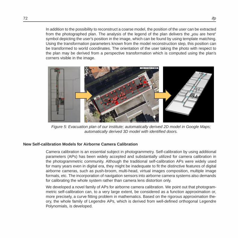
72 ifp
In addition to the possibility to reconstruct a coarse model, the position of the user can be extractedfrom the photographed plan. The analysis of the legend of the plan delivers the
”you are here“
symbol depicting the user’s position in the image, which can be found by using template matching.Using the transformation parameters known from the model reconstruction step, this position canbe transformed to world coordinates. The orientation of the user taking the photo with respect tothe plan may be derived from a perspective transformation which is computed using the plan’scorners visible in the image.
Figure 5: Evacuation plan of our institute; automatically derived 2D model in Google Maps;automatically derived 3D model with identified doors.
New Self-calibration Models for Airborne Camera Calibration
Camera calibration is an essential subject in photogrammetry. Self-calibration by using additionalparameters (APs) has been widely accepted and substantially utilized for camera calibration inthe photogrammetric community. Although the traditional self-calibration APs were widely usedfor many years even in digital era, they might be inadequate to fit the distinctive features of digitalairborne cameras, such as push-broom, multi-head, virtual images composition, multiple imageformats, etc. The incorporation of navigation sensors into airborne camera systems also demandsfor calibrating the whole system rather than camera lens distortion only.
We developed a novel family of APs for airborne camera calibration. We point out that photogram-metric self-calibration can, to a very large extent, be considered as a function approximation or,more precisely, a curve fitting problem in mathematics. Based on the rigorous approximation the-ory, the whole family of Legendre APs, which is derived from well-defined orthogonal LegendrePolynomials, is developed.
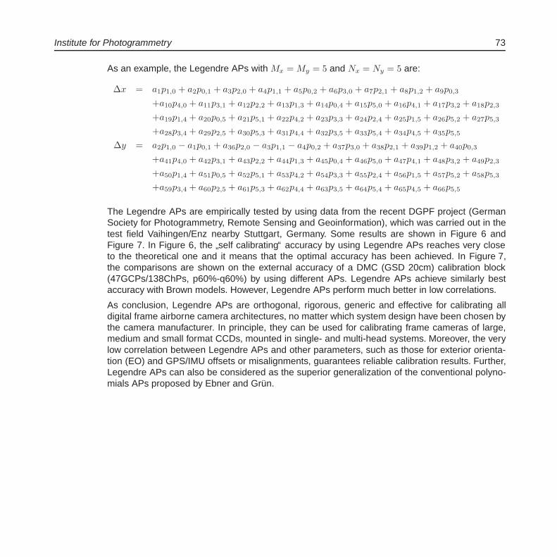
Institute for Photogrammetry 73
As an example, the Legendre APs with Mx = My = 5 and Nx = Ny = 5 are:
Δx = a1p1,0 + a2p0,1 + a3p2,0 + a4p1,1 + a5p0,2 + a6p3,0 + a7p2,1 + a8p1,2 + a9p0,3
+a10p4,0 + a11p3,1 + a12p2,2 + a13p1,3 + a14p0,4 + a15p5,0 + a16p4,1 + a17p3,2 + a18p2,3
+a19p1,4 + a20p0,5 + a21p5,1 + a22p4,2 + a23p3,3 + a24p2,4 + a25p1,5 + a26p5,2 + a27p5,3
+a28p3,4 + a29p2,5 + a30p5,3 + a31p4,4 + a32p3,5 + a33p5,4 + a34p4,5 + a35p5,5
Δy = a2p1,0 − a1p0,1 + a36p2,0 − a3p1,1 − a4p0,2 + a37p3,0 + a38p2,1 + a39p1,2 + a40p0,3
+a41p4,0 + a42p3,1 + a43p2,2 + a44p1,3 + a45p0,4 + a46p5,0 + a47p4,1 + a48p3,2 + a49p2,3
+a50p1,4 + a51p0,5 + a52p5,1 + a53p4,2 + a54p3,3 + a55p2,4 + a56p1,5 + a57p5,2 + a58p5,3
+a59p3,4 + a60p2,5 + a61p5,3 + a62p4,4 + a63p3,5 + a64p5,4 + a65p4,5 + a66p5,5
The Legendre APs are empirically tested by using data from the recent DGPF project (GermanSociety for Photogrammetry, Remote Sensing and Geoinformation), which was carried out in thetest field Vaihingen/Enz nearby Stuttgart, Germany. Some results are shown in Figure 6 andFigure 7. In Figure 6, the
”self calibrating“ accuracy by using Legendre APs reaches very close
to the theoretical one and it means that the optimal accuracy has been achieved. In Figure 7,the comparisons are shown on the external accuracy of a DMC (GSD 20cm) calibration block(47GCPs/138ChPs, p60%-q60%) by using different APs. Legendre APs achieve similarly bestaccuracy with Brown models. However, Legendre APs perform much better in low correlations.
As conclusion, Legendre APs are orthogonal, rigorous, generic and effective for calibrating alldigital frame airborne camera architectures, no matter which system design have been chosen bythe camera manufacturer. In principle, they can be used for calibrating frame cameras of large,medium and small format CCDs, mounted in single- and multi-head systems. Moreover, the verylow correlation between Legendre APs and other parameters, such as those for exterior orienta-tion (EO) and GPS/IMU offsets or misalignments, guarantees reliable calibration results. Further,Legendre APs can also be considered as the superior generalization of the conventional polyno-mials APs proposed by Ebner and Grun.
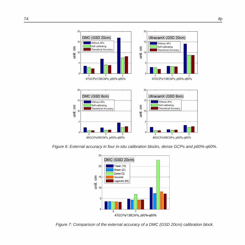
74 ifp
Figure 6: External accuracy in four in-situ calibration blocks, dense GCPs and p60%-q60%.
Figure 7: Comparison of the external accuracy of a DMC (GSD 20cm) calibration block.
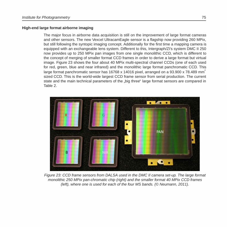
Institute for Photogrammetry 75
High-end large format airborne imaging
The major focus in airborne data acquisition is still on the improvement of large format camerasand other sensors. The new Vexcel UltracamEagle sensor is a flagship now providing 260 MPix,but still following the syntopic imaging concept. Additionally for the first time a mapping camera isequipped with an exchangeable lens system. Different to this, Intergraph/ZI’s system DMC II 250now provides up to 250 MPix pan images from one single monolithic CCD, which is different tothe concept of merging of smaller format CCD frames in order to derive a large format but virtualimage. Figure 23 shows the four about 40 MPix multi-spectral channel CCDs (one of each usedfor red, green, blue and near infrared) and the monolithic large format panchromatic CCD. Thislarge format panchromatic sensor has 16768 x 14016 pixel, arranged on a 93.900 x 78.489 mm
2
sized CCD. This is the world-wide largest CCD frame sensor from serial production. The currentstate and the main technical parameters of the
”big three“ large format sensors are compared in
Table 2.
Figure 23: CCD frame sensors from DALSA used in the DMC II camera set-up. The large formatmonolithic 250 MPix pan-chromatic chip (right) and the smaller format 40 MPix CCD frames
(left), where one is used for each of the four MS bands. (© Neumann, 2011).

76 ifp
Table 2: Main parameters of current large format digital airborne mapping systems.
In addition to those developments in large format imaging, there also is quite some progress inthe so-called
”medium-format sector“. Most recent systems now are reaching up to 80 MPix (per
camera head) and offer improved image quality due to forward motion compensation and in caseof the Leica Geosystems RCD30 parallel RGB and NIR image acquisition.This also shows the increased role of multi-spectral data acquisition which now merges the formerclearly separated worlds of geometrically focused photogrammetry and remote sensing relyingon multi-spectral data classification. Radiometry in general is increasing in importance. With thenew digital airborne cameras the clear separation between geometry and radiometry, which to acertain extend was due to the available sensor technologies, now is close to vanish. It is the movefrom analog to digital airborne imaging forcing this change. The much better radiometric quality ofdigitally recorded image data in comparison to scanned analog imagery is commonly accepted.But this only is one part of the advantages of digital image recording. The other aspect is thatphoto sensitive electronic devices have a linear characteristic curve describing the relation be-tween exposure and density. This is different to film, where the light is recorded in an s-shapedlogarithmic curve, dependent on the settings of the exposures and the later film development. Indigital imaging this curve is linear per se, i.e. the relation between exposure and density does notchange. If this function is known from radiometric calibration, the light rays, which are measuredby individual pixels directly relate to a physical property of the imaged object. In addition, the multi-spectral capabilities should be mentioned. In the digital world, filters could be defined exactly tothe user’s need, which is much more complicated with color sensitive emulsions of a color film.This advantage of electro-optical sensors offers new fields of application in remote sensing, whichalready is established in satellite imaging for decades but new for the airborne imaging sensors.But all this also requests for extended radiometric calibrations of digital cameras in additional tothe former geometric calibration only. This is why manufacturers as well as (first) users put in-creasing effort in the radiometric calibration of those sensors. This can be done from laboratoryor via vicarious calibration from test sites, as it was analyzed in a recently finished project on the
”Radiometric aspects of digital photogrammetric images“ organized by the European Spatial Data
Research organization (EuroSDR).
Institute for Photogrammetry 77
Multi-camera System for close range point cloud acquisition
In March 2011 the ifp has got an industrial contract to collect photos for a dense 3D point cloudgeneration of the two Tympana of the Royal Palace in Amsterdam. The work took place as partof the restoration work which was carried out at the whole building. For this purpose we plannedto use a multi-camera system incorporating a structure-and-motion and a dense matching imple-mentation. Regarding the hardware, one goal for the Amsterdam project was to combine low tomedium cost hardware components to set-up a more sophisticated multi-sensor system.
The multi-camera configuration enables us to obtain a high resolution point cloud from one singleshot. The sensor design was customized to meet certain requirements and restrictions. First of allour assignment was to scan the object with a point sampling distance of 1mm or less and with anaccuracy of 1mm or better within twelve days. Furthermore the sensor needed to be small sizedand light weighted to be applicable in the given surroundings. Also considerations made in theprocess of project planning and software implementation directly influenced some aspects of thesensor design and vice versa.
We chose to use industrial cameras as they are very small and light weighted and known to berobust. We defined the overlap of the images to be roughly 90% in both image directions at a work-ing distance of 70cm in order to maintain a sufficient overlap at shorter distances. Based on thisconstraint we computed a base length of ≈ 7,5cm. Assuming an image measurement accuracyof 0.3 pixels this configuration easily holds the requirements. Having set up the configuration forsingle shot data acquisition, the next crucial issue was the registration of the single point clouds.We decided to use photogrammetric bundle adjustment to solve the registration task. Again a highoverlap between the images of the different stations is benefitting to the stability of the results. Forthis purpose we incorporated a fifth camera with even shorter focal length to the system.
All five cameras have been mounted to two custom aluminum adapter plates, which again havebeen mounted on an aluminum profile. This construction is very compact and provides high sta-bility. For protection of the cameras it was extended by further aluminum profiles surrounding thecameras as a rigid frame (Figure 8). The whole construction has a size of ≈ 25x25x15cm and aweight of roughly 2kg (not taking into account the cables).
Enhancement of the object’s surface texture was another important issue to be solved in order togenerate high quality matching results. Although the freestone surface provided a good texture atlarge areas there also were areas with homogenous characteristics and also a lot of areas whichhave been darkened by environmental influences. In such cases, correspondences in the imagescan either not be found or are ambiguous. In any case, such areas cannot be reconstructed accu-rately. Thus we decided to use active texture projection in our task. We added a MS Kinect deviceto our system, using only its’ IR laser projector. Equipping the four matching cameras with 670nmblocking filters made the pattern visible to them while keeping it invisible to the bundle camera.Thus the bundle adjustment process, which incorporates automatic feature point extraction, is notinfluenced by the pattern moving with the sensor.

78 ifp
Figure 8: The Amsterdam sensor. Five cameras rigidly mounted and protected by an aluminumframe. A MS Kinect device provides additional texture projection.
Figure 9: Image taken by one of the matching cameras. The white speckles covering the lionhead’s surface are produced by the Kinect’s IR laser projector and are not visible to the bundle
camera. The image has been slightly enhanced to make the pattern easier to see for the reader.

Institute for Photogrammetry 79
Efficient Reconstruction of Large Unordered Image Datasets
The reconstruction of camera orientations and structure from unordered image datasets, alsoknown as Structure and Motion reconstruction, has become an important task in photogramme-try. Current solutions require high computational efforts for image networks with high complexityand diversity. Unlike the methods suitable for landmark reconstruction from large-scale internetimage collections, we focus on datasets where one cannot reduce the number of images withoutlosing geometric information of the dataset. The exterior orientations can be derived preciselyand automatically using feature extraction and matching with only few and rough initial informa-tion about the lens and the camera. Accurate intrinsic orientations are estimated as well usingself-calibration methods.
Structure and Motion (SaM) methods enable the reconstruction of orientations and geometry fromimagery with little prior information about the camera. The derived orientations are commonlyused within dense surface reconstruction methods, which provide point clouds or meshes withhigh resolution. This modular pipeline is employed for different applications as affordable andefficient approach to solve typical surveying tasks.
Therefore, a pipeline was developed focusing on efficiency and accuracy. As shown in Figure 10,it is divided into four processing steps. It employs an initial image network analysis in order toavoid the costly matching of all possible image pairs and to guide the reconstruction process. Thefollowing tie point generation is designed to derive points with maximum accuracy and reliability.By building and optimizing a graph based on the image network, the dataset can be split intoreliable patches of neighboring images which can be processed independently and in parallelwithin the reconstruction step. Finally, all patches are merged and optimized by a global bundleadjustment. Ground control points can be integrated within this step as well.
Figure 10: Flowchart of the pipeline.
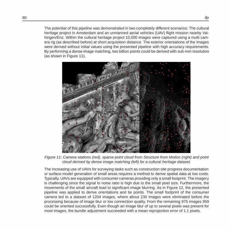
80 ifp
The potential of this pipeline was demonstrated in two completely different scenarios: The culturalheritage project in Amsterdam and an unmanned aerial vehicles (UAV) flight mission nearby Vai-hingen/Enz. Within the cultural heritage project 10,000 images were captured using a multi cam-era rig (as described before) at short acquisition distance. The exterior orientations of the imageswere derived without initial values using the presented pipeline with high accuracy requirements.By performing a dense image matching, two billion points could be derived with sub-mm resolution(as shown in Figure 11).
Figure 11: Camera stations (red), sparse point cloud from Structure from Motion (right) and pointcloud derived by dense image matching (left) for a cultural heritage dataset.
The increasing use of UAVs for surveying tasks such as construction site progress documentationor surface model generation of small areas requires a method to derive spatial data at low costs.Typically, UAVs are equipped with consumer cameras providing only a small footprint. The imageryis challenging since the signal to noise ratio is high due to the small pixel size. Furthermore, themovements of the small aircraft lead to significant image blurring. As in Figure 12, the presentedpipeline was applied to derive orientations and tie points. The small footprint of the consumercamera led to a dataset of 1204 images, where about 230 images were eliminated before theprocessing because of image blur or low connection quality. From the remaining 975 images 959could be oriented successfully. Even though an image blur of up to several pixels was present formost images, the bundle adjustment succeeded with a mean reprojection error of 1.1 pixels.
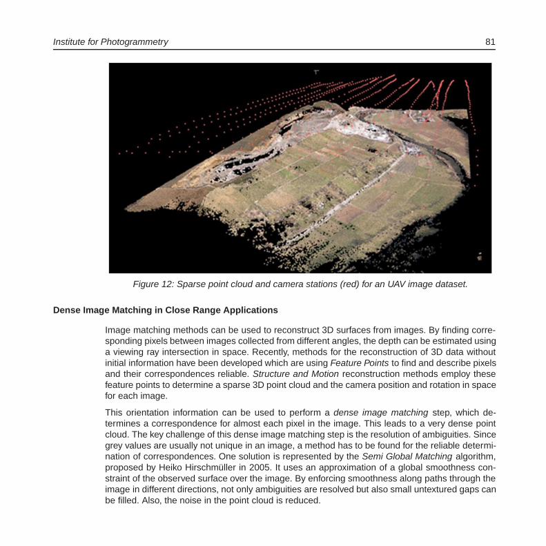
Institute for Photogrammetry 81
Figure 12: Sparse point cloud and camera stations (red) for an UAV image dataset.
Dense Image Matching in Close Range Applications
Image matching methods can be used to reconstruct 3D surfaces from images. By finding corre-sponding pixels between images collected from different angles, the depth can be estimated usinga viewing ray intersection in space. Recently, methods for the reconstruction of 3D data withoutinitial information have been developed which are using Feature Points to find and describe pixelsand their correspondences reliable. Structure and Motion reconstruction methods employ thesefeature points to determine a sparse 3D point cloud and the camera position and rotation in spacefor each image.
This orientation information can be used to perform a dense image matching step, which de-termines a correspondence for almost each pixel in the image. This leads to a very dense pointcloud. The key challenge of this dense image matching step is the resolution of ambiguities. Sincegrey values are usually not unique in an image, a method has to be found for the reliable determi-nation of correspondences. One solution is represented by the Semi Global Matching algorithm,proposed by Heiko Hirschmuller in 2005. It uses an approximation of a global smoothness con-straint of the observed surface over the image. By enforcing smoothness along paths through theimage in different directions, not only ambiguities are resolved but also small untextured gaps canbe filled. Also, the noise in the point cloud is reduced.

82 ifp
However, the Semi Global Matching algorithm was initially developed for the processing of aerialimagery, where the depth in relation to the acquisition distance is small. This is not the case forclose range applications, where large depth variations can occur. In order to be able to processhigh resolution imagery from close range scenes, the Semi Global Matching algorithm was mod-ified. Usually, all possible correspondences are evaluated for each pixel and for each possibledepth within a certain range. Since this range is very large for close range imagery, the require-ments regarding computation time and physical memory are very high. Thus, we implemented ahierarchical approach, where the depth search range is reduced for each pixel individually usingan image pyramid. On low resolutions the possible depths are also significantly smaller, whichenables very fast computations. By using this information as initial information in the next higherlevel of resolution the depth range can be narrowed down subsequently. By matching not only onone stereo pair, but many images instead, redundant observations are available for each pointon the object surface. These multiple observations in image space to the object point enable atriangulation with noise reduction and outlier rejection. Consequently, a reliable low noise pointcloud can be derived with quality information for each point.
Within a cultural heritage data recording project this modified dense image method was usedin combination with an extended Structure and Motion technique to acquire point clouds with aresolution and accuracy below 1mm. The objects were the two Tympanums at the Royal Palace ofAmsterdam with a complex relief surface covering an area of about 125m
2. Within 10 days 10,000
images were acquired using a multi-camera rig decribed above, which we specifically designedfor acquiring such complex geometries at short distance. Finally, about 2 billion 3D points werecomputed.
Figure 13: Dense image matching: finding corresponding pixels and intersecting their viewingrays in space.

Institute for Photogrammetry 83
Figure 14: Point cloud extract from the Amsterdam project. 2 Billion 3D points were derived fromabout 10,000 images with sub-mm resolution and accuracy.
A Low-Cost Close-Range System for Indoor Modeling and Navigation
In recent years, active sensing is widely needed in many indoor applications like indoor 3D model-ing, indoor navigation, mobile mapping, etc. This can be maintained using laser scanners (expen-sive and relatively large), or time of flight cameras (less expensive but low accurate). A low-costalternative can be the Microsoft Kinect system which was originally designed as a user inter-face for the Xbox 360 game console. This system delivers dense point clouds of the environment(based on matching IR projected patterns) together with color images, both at a rate of 30Hz. Onecan expect a noise of about 3cm at 3m distance for the generated point clouds. Geometrical andoptical calibration of the system allows for the generation of textured point clouds.
The point clouds collected from different viewpoints can be aligned using geometrical and visualinformation derived from the range sensor and RGB camera respectively. Figure 15 shows anexample of automatic alignment of multiple point clouds, using visual information extracted fromcolor images. In this example, SIFT features are extracted and matched in consecutive colorimages. Such features can then be transformed to a relative 3D coordinate system, having thestereo system calibrated. The matched 3D points can be directly used to approximately align theconsecutive point clouds, which can be further improved using an ICP (iterative closest point)algorithm.
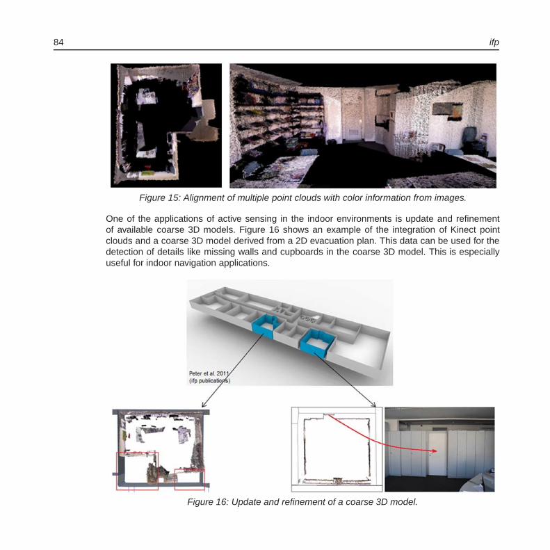
84 ifp
Figure 15: Alignment of multiple point clouds with color information from images.
One of the applications of active sensing in the indoor environments is update and refinementof available coarse 3D models. Figure 16 shows an example of the integration of Kinect pointclouds and a coarse 3D model derived from a 2D evacuation plan. This data can be used for thedetection of details like missing walls and cupboards in the coarse 3D model. This is especiallyuseful for indoor navigation applications.
Figure 16: Update and refinement of a coarse 3D model.

Institute for Photogrammetry 85
Fast and Automatic Combination of Digital Images and Laser Scanner Data
Integration of close-range photogrammetry and terrestrial laser scanning techniques has to beperformed in order to improve the geometry and the visual quality of collected 3D models. More-over, this combination is needed to fill gaps in laser point clouds to avoid modeling errors, re-construct more details in higher resolution and to recover simple structures with less geometricdetails. Therefore, we present a fast and flexible procedure for the automatic combination of digitalimages and laser scanner data (Figure 17).
Figure 17: Processing chain for combining digital images and laser scanner data.
After the collection of laser scanner point clouds and photogrammetric images, a preprocessing ofthe data is performed. Then, a co-registration step is carried out in order to get the camera abso-lute orientation starting by extracting Affine-SIFT (ASIFT) features with their descriptors from thereflectance and digital images. As the features in both images are detected, a feature matchingprocess based on the detected feature descriptors is followed in order to compute the 3D-to-2Dcorrespondences. This step requires a refinement process by means of a RANSAC algorithm
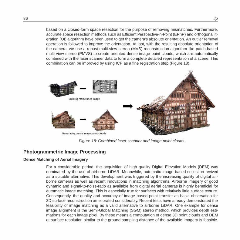
86 ifp
based on a closed-form space resection for the purpose of removing mismatches. Furthermore,accurate space resection methods such as Efficient Perspective-n-Point (EPnP) and orthogonal it-eration (OI) algorithm have been used to get the camera’s absolute orientation. An outlier removaloperation is followed to improve the orientation. At last, with the resulting absolute orientation ofthe camera, we use a robust multi-view stereo (MVS) reconstruction algorithm like patch-basedmulti-view stereo (PMVS) to create oriented dense image point clouds, which are automaticallycombined with the laser scanner data to form a complete detailed representation of a scene. Thiscombination can be improved by using ICP as a fine registration step (Figure 18).
Figure 18: Combined laser scanner and image point clouds.
Photogrammetric Image Processing
Dense Matching of Aerial Imagery
For a considerable period, the acquisition of high quality Digital Elevation Models (DEM) wasdominated by the use of airborne LiDAR. Meanwhile, automatic image based collection revivedas a suitable alternative. This development was triggered by the increasing quality of digital air-borne cameras as well as recent innovations in matching algorithms. Airborne imagery of gooddynamic and signal-to-noise-ratio as available from digital aerial cameras is highly beneficial forautomatic image matching. This is especially true for surfaces with relatively little surface texture.Consequently, the quality and accuracy of image based point transfer as basic observation for3D surface reconstruction ameliorated considerably. Recent tests have already demonstrated thefeasibility of image matching as a valid alternative to airborne LiDAR. One example for denseimage alignment is the Semi-Global Matching (SGM) stereo method, which provides depth esti-mations for each image pixel. By these means a computation of dense 3D point clouds and DEMat surface resolution similar to the ground sampling distance of the available imagery is feasible.
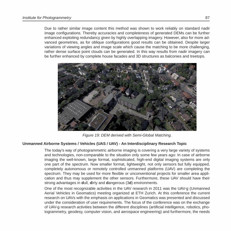
Institute for Photogrammetry 87
Due to rather similar image content this method was shown to work reliably on standard nadirimage configurations. Thereby accuracies and completeness of generated DEMs can be furtherenhanced exploiting redundancy given by highly overlapping imagery. However, also for more ad-vanced geometries, as for oblique configurations good results can be obtained. Despite largervariations of viewing angles and image scale which cause the matching to be more challenging,rather dense surface point clouds can be generated. In this way results from nadir imagery canbe further enhanced by complete house facades and 3D structures as balconies and treetops.
Figure 19: DEM derived with Semi-Global Matching.
Unmanned Airborne Systems / Vehicles (UAS / UAV) - An Interdisciplinary Research Topic
The today’s way of photogrammetric airborne imaging is covering a very large variety of systemsand technologies, non-comparable to the situation only some few years ago: In case of airborneimaging the well-known, large format, sophisticated, high-end digital imaging systems are onlyone part of the spectrum. Now smaller format, lightweight, not only sensors but fully equipped,completely autonomous or remotely controlled unmanned platforms (UAV) are completing thespectrum. They may be used for more flexible or unconventional projects for smaller area appli-cation and thus may supplement the other sensors. Furthermore, these UAV should have theirstrong advantages in dull, dirty and dangerous (3d) environments.
One of the most recognizable activities in the UAV research in 2011 was the UAV-g (UnmannedAerial Vehicles in Geomatics) meeting organized at ETH Zurich. At this conference the currentresearch on UAVs with the emphasis on applications in Geomatics was presented and discussedunder the consideration of user requirements. The focus of the conference was on the exchangeof UAV-g research activities between the different disciplines (artificial intelligence, robotics, pho-togrammetry, geodesy, computer vision, and aerospace engineering) and furthermore, the needs
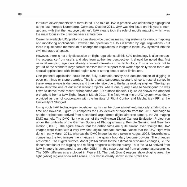
88 ifp
for future developments were formulated. The role of UAV in practice was additionally highlightedat the last Intergeo Nuremberg, Germany, October 2011. UAV was the issue on this year’s Inter-geo and with that the new
”eye catcher“. UAV clearly took the role of mobile mapping which was
the main focus in the previous years at Intergeo.
Currently available UAV platforms can already be used as measuring systems for various mappingand monitoring applications. However, the operation of UAVs is limited by legal regulations - butthere is quite some momentum to change the regulations to integrate these UAV systems into thecivil managed airspace.
However, there is not only discussion on flight regulations, all this UAV-technology is also increas-ing acceptance from user’s and also from authorities perspective. It should be noted that firstnational mapping agencies already showed interests in this technology. This is for sure not toget rid of the standard large format sensors but to support their work especially when there arespecial applications with limited region size or strong time or other limitations.
One potential application could be the fully automatic survey and documentation of digging inopen pit mines or stone quarries. This is a quite dangerous scenario since terrestrial survey inthese areas always is dangerous and time intensive due to the large working engines. The figuresbelow illustrate one of our most recent projects, where one quarry close to Vaihingen/Enz wasflown to derive most recent orthophotos and 3D surface models. Figure 20 shows the drappedorthophoto from a UAV flight, flown in March 2011. The fixed-wing micro UAV system was kindlyprovided as part of cooperation with the Institute of Flight Control and Mechanics (IFR) at theUniversity of Stuttgart.
Using such UAV technologies repetitive flights can be done almost automatically at almost anytime and low-cost. Figure 21 compares the UAV derived orthophoto from the 2011 campaign toanother orthophoto derived from a standard large format digital airborne camera, the Z/I ImagingDMC namely. The DMC flight was part of the well-known Digital Camera Evaluation Project rununder the umbrella of the German Society of Photogrammetry, Remote Sensing and Geoinfor-mation (DGPF). The figure shows, that the orthophotos are quite similar, even though the UAVimages were taken with a very low cost, digital compact camera. Notice that the UAV flight wasdone in early March 2011, whereas the DMC imageries were taken in August 2008. Nevertheless,comparing the two images the changes in the quarry boundary become obvious. The changesare circled. The Digital Surface Model (DSM) allows for the estimation of volume changes, i.e. thedocumentation of the digging and re-filling progress within the quarry. Thus the DSM derived fromUAV imagery is compared to an older DSM - in this case obtained from airborne laserscanning.The DSM differences are plotted in Figure 22. The dark (black) regions show digging area, thelight (white) regions show refill zones. This also is clearly shown in the profile line.
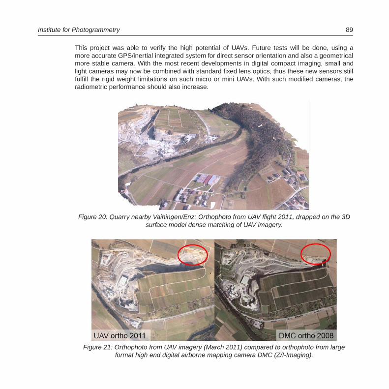
Institute for Photogrammetry 89
This project was able to verify the high potential of UAVs. Future tests will be done, using amore accurate GPS/inertial integrated system for direct sensor orientation and also a geometricalmore stable camera. With the most recent developments in digital compact imaging, small andlight cameras may now be combined with standard fixed lens optics, thus these new sensors stillfulfill the rigid weight limitations on such micro or mini UAVs. With such modified cameras, theradiometric performance should also increase.
Figure 20: Quarry nearby Vaihingen/Enz: Orthophoto from UAV flight 2011, drapped on the 3Dsurface model dense matching of UAV imagery.
Figure 21: Orthophoto from UAV imagery (March 2011) compared to orthophoto from largeformat high end digital airborne mapping camera DMC (Z/I-Imaging).

90 ifp
Figure 22: DSM height differences and difference profil: DSM from UAV images compared to alaserscanner reference DSM.
References 2011Abdel-Wahab, M., Wenzel, K., Fritsch D.: Reconstruction of Orientation and Geometry from large
Unordered Datasets for Low Cost Applications. Proceedings LC3D Workshop, Berlin, De-cember 2011 (published on CD-ROM).
Becker, S.: Automatische Ableitung und Anwendung von Regeln fur die Rekonstruktion von Fas-saden aus heterogenen Sensordaten. Deutsche Geodatische Kommission, Reihe C, Nr.658, Munchen 2011, ISBN 978-3-7696-5070-9, 156p.
Becker, S.: Towards Complete LOD3 Models - Automatic Interpretation of Building Structures.Photogrammetric Week ’11, Ed. D. Fritsch, Wichmann, Berlin/Offenbach, 39-56.
Becker, S.: Gebauderekonstruktion durch Anwendung automatisch abgeleiteter Regeln. In: Pro-ceedings of 106. DVW-Seminar Terrestrisches Laserscanning - TLS 2011 mit TLS-Challenge, Schriftenreihe des DVW Band 66 / 2011, Wißner Verlag, 133-145.
Chen, H.: Entwicklung von Verfahren zur Beurteilung und Verbesserung der Qualitat von Naviga-tionsdaten. Dissertation, Universitat Stuttgart 2011, 127p.

Institute for Photogrammetry 91
Cramer, M.: Geoemetry Perfect - Radiometry Unknown? Photogrammetric Week ’11, Ed. D.Fritsch, Wichmann, Berlin/Offenbach, 65-77.
Fritsch, D. (Ed.): Photogrammetric Week ’11. Wichmann, Berlin/Offenbach, 330p.
Fritsch, D.: Multiray Photogrammetry Meets Advanced LiDAR. Photogrammetric Week ’11, Ed. D.Fritsch, Wichmann, Berlin/Offenbach, V-X.
Fritsch, D.: A Synopsis of the Carl Pulfrich Award. Photogrammetric Week ’11, Ed. D. Fritsch,Wichmann, Berlin/Offenbach, 57-61.
Fritsch, D., Khosravani, A.M., Cefalu, A., Wenzel, K.: Multi-Sensors and Multiray Reconstruc-tion for Digital Preservation. Photogrammetric Week ’11, Ed. D. Fritsch, Wichmann,Berlin/Offenbach, 305-323.
Fritsch, D., Haala, N., Walter, V., Becker, S., Budroni, A., Wenzel, K., Kosravani, A., Milius, J.,Petters, C.: All About Point Clouds. Lecture Notes Tutorial Photogrammetric Week ´11.Institute for Photogrammetry, University of Stuttgart, 280p.
Haala, N.: Multiray Photogrammetry and Dense Image Matching. Photogrammetric Week ’11, Ed.D. Fritsch, Wichmann, Berlin/Offenbach, 185-195.
Haala, N., Cramer, M., Weimer, F., Trittler, M.: Performance Test on UAV-based data collectionProceedings of the International Conference on Unmanned Aerial Vehicle in Geomatics(UAV-g). IAPRS, Volume XXXVIII-1/C22, Zurich, Switzerland, 2011, 6p (published on CD-ROM).
Haala, N., Fritsch, D., Peter, M., Khosravani, A.: Pedestrian navigation and modeling for indoor en-vironments. 7th International Symposium on Mobile Mapping Technology, Crakow, Poland,6p (published on CD-ROM).
Peter, M., Haala, N., Fritsch, D.: Using Photographed Evacuation Plans to Support MEMS IMUNavigation. In: Proceedings of the 2011 International Conference on Indoor Positioningand Indoor Navigation (IPIN2011), Guimaraes, Portugal, 2011, 4p (published on CD-ROM).
Rothermel, M., Haala, N.: Potential of Dense Matching for the Generation of High Quality DigitalElevation Models. ISPRS Hannover Workshop 2011: High-Resolution Earth Imaging forGeospatial Information, IASPRS, Volume XXXVIII-4/W19 (published on CD-ROM).
Rothermel, M., Haala, N., Wenzel, K.: Potential dichter Bildzuordnung fur die Erzeugungvon Hohenmodellen. DGPF Tagungsband 20/2011 - 31. Wissenschaftlich-TechnischeJahrestagung der DGPF, 109-118.
Schmitz, B., Becker, S., Blessing, A., Großmann, M.: Acquisition and Presentation of DiverseSpatial Context Data for Blind Navigation. In: Proceedings of the 12th IEEE InternationalConference on Mobile Data Management (MDM 2011), 276-284.

92 ifp
Tang, R., Cramer M., Fritsch D.: Application of Bayesian Statistics in Photogrammetric BundleAdjustment. Procedia Environmental Sciences (Elsevier online journal), issue on
”Spatial
Statistics 2011“, Vol. 3, 75-80.
Walter, V., Luo, F.: Automatic Interpretation of Digital Maps. ISPRS Journal of Photogrammetryand Remote Sensing 66(4), 519-528.
Wenzel, K., Abdel-Wahab, M., Cefalu, A., Fritsch D.: A Multi-Camera System for Efficient PointCloud Recording in Close Range Applications. LC3D workshop, Berlin, December 2011(published on CD-ROM).
Zavoti, J., Fritsch, D.: A First Attempt at a new Algebraic Solution of the Exterior Orientation inPhotogrammetry. Acta Geod-Geoph. Hung., Vol. 46(3), 317-325.
Doctoral Theses
Hainan, C.: Entwicklung von Verfahren zur Beurteilung und Verbesserung der Qualitat von Nav-igationsdaten. Dissertation, Universitat Stuttgart 2011, 127p, Supervisor: Fritsch, D., Co-Supervisor: Meng, L.
Diploma Theses / Master Theses
Shakir, A.R.: Toponym recognition in scanned color topographic maps. Supervisor: Walter, V.
Daniel, K.: Volumetric Range Image Integration. Supervisors: Haala, N., Wenzel, K.
Sebastian, G.: Entwicklung einer Auskunfts- und Qualifizierungskomponente fur ALKIS. Supervi-sor: Walter, V.
Mulkal: Determination of the Best Image Segmentation Algorithm for an Image. Supervisor:Walter, V.
Omidalizarandi, M.: Segmentation and classification of point clouds from dense aerial imagematching. Supervisor: Haala, N.
Hu, X.: Methods for quality control of large Cartosat-1 stereo blocks. Supervisors: d’Angelo, P.(DLR), Cramer, M.
Zhou, D.: An Investigation of Semi-Global Matching using Mutual Information. Supervisor:Haala, N.
Li, C.: Detection and Classification of General Text Elements in Video. Supervisor: Fritsch, D.
Study Theses / Bachelor Theses
Schwarz, C.: Untersuchung von CBIR Verfahren zur Zuordnung von Landern, Supervisor:Walter, V.

Institute for Photogrammetry 93
Activities in National and International OrganizationsCramer, M.:
President EuroSDR Technical Commission I - Sensors, primary data acquisition and geo-referencingCo-Chair ISPRS Working Group I/5 - Integrated Systems for Sensor Georeferencing andNavigation
Englich, M.:Webmaster ISPRS
Fritsch, D.:Chairman Board of Trustees ‘The ISPRS Foundation’Member CyberOne Award CommiteeMember Galileo/GMES Award Committee Baden-WurttembergMember Scientific Advisory Committee DFG Project ArcheInv, Univ. BochumMember Jury Artur Fischer Invention AwardMember D21 Advisory BoardMember Board of Trustees German University in Cairo (GUC)Member GUC Academic Advisory CommitteeMember Apple’s University Education Forum (UEF)Member Advisory Board ISPRSVice-President Research EuroSDR
Haala, N.:Co-Chair ISPRS WG III/4 - Automatic Image Interpretation for City-ModellingVorsitz DGPF Arbeitskreis Sensorik und Plattformen
Walter, V.:Nationaler Berichterstatter fur die ISPRS Kommission IV
Education - Lectures/Exercises/Training/SeminarsBachelor Geodasie und Geoinformatik
Introduction into Geodesy and Geoinformatics 4/2/0/0(Cramer, Fritsch, Sneeuw, Keller, Kleusberg)
Adjustment Theory I (Fritsch, Sneeuw) 1/1/0/0Adjustment Theory II (Fritsch, Sneeuw) 2/2/0/0Geoinformatics I (Fritsch, Walter) 2/2/0/0Geoinformatics II (Walter) 1/1/0/0Image Processing (Haala) 2/1/0/0Photogrammetry (Cramer) 2/1/0/0Signal Processing (Fritsch) 2/1/0/0

94 ifp
Diplomstudiengang Geodasie und Geoinformatik
Aerotriangulation and Stereoplotting (Cramer) 2/1/0/0Advanced Projects in Photogrammetry and GIS (Cramer, Haala, Walter) 1/2/0/0Animation and Visualisation of Geodata (Haala, Kada) 1/1/0/0Cartography (Urbanke) 1/0/0/0Close Range Photogrammetry (Fritsch) 2/1/0/0Databases and Geoinformation Systems (Walter) 2/1/0/0Digital Image Processing (Haala) 2/1/0/0Digital Terrain Models (Haala) 1/1/0/0Geodetic Seminar I, II (Fritsch, Sneeuw, Keller, Kleusberg) 0/0/0/4Integrated Fieldworks (Fritsch, Sneeuw, Keller, Kleusberg) 0/0/4/0Pattern Recognition and Image Based Geodata Collection (Haala) 2/1/0/0Urban Planning (Dvorak) 1/0/0/0
Master Course GEOENGINE
Airborne Data Acquisition (Fritsch, Cramer) 1/1/0/0Geoinformatics (Fritsch, Walter) 2/1/0/0Signal Processing (Fritsch) 2/1/0/0Topology and Optimisation (Fritsch) 2/1/0/0Integrated Fieldworks (Fritsch, Sneeuw, Keller, Kleusberg) 0/0/4/0
Master Courses ”Infrastructure Planning“ and ”Water Resource Management“
Introduction to GIS (Walter) 2/0/0/0Advanced GIS (Walter) 2/0/0/0
Diplomstudiengang Geographie Tubingen
Practical Training in GIS (Walter) 0/0/4/0
Diplomstudiengang Luft- und Raumfahrttechnik
Introduction into Photogrammetry (Cramer) 2/0/0/0


