23
SU-6010 User's Manual 140409-V1.1

SU-6010 User's Manual140409-V1.1
Chapter 1 Features ............................................................ Chapter 2 Introduction ....................................................... Chapter 3 Package Contents .............................................Chapter 4 Applications .......................................................Chapter 5 SU-6010 Programmer Base Overview ..............Chapter 6 SU-6010 eMMC Adapter Overview ...................Chapter 7 SU-6010 Dimensions ........................................Chapter 8 SU-6010 Installation ..........................................Chapter 9 SU-6010 Programmer Application......................Chapter 10 SU-6010 Practical Operation ..........................Appendix 1 : FAQ ............................................................... Appendix 2 : Info Required for eMMC Manual Program.....
Contents
34457891112192223
SU-6010 User's Manual

SU-6010 User's Manual
3
Chapter 1 Features
Supports Windows XP (x86), and Windows Vista / 7 / 8 (x86/x64).
USB 2.0 High-Speed Connection to Host PC.
Supports MMCA V.4.51, 3.3 or 1.8V eMMC.
MMC Interface up to 8 bit, 50MHz bus.
Supports eMMC BA/AA/AB/AC Types of BGA Packages.
Supports eMMC proprietary POP Packages via external adapters. (Not included in the
pacakge.)
Supports eMMC BP, GP and ENH_USER Partition, Program and Verify.
Supports Leap Electronic eMMC duplicator’s Partition/Mirror/User/AutoScan Modes.
Single partition access mode for BP, GP or user data supporting raw binary data.
Easy to use, automatic parameter checking “eMMC Partition Settings” feature.
Special BP1 + BP2 + User_Data mode.
Special Bottom Align Mode.
ts Windows XP (x86) and Windows Vista / 7 / 8 (x86/x64)

SU-6010 User's Manual
4
Chapter 2 Introduction
Chapter 3 Package Contents
SU-6010 USB Programmer is the handy tool for engineers working with eMMC. SU-6010
offers easy adaptation to all kinds of popular eMMC packages without needs for additional
adapter. In case if other proprietary packages are used, SU-6010 provides SD/MMC socket
for use with external adapter.
SU-6010 comes with easy-to-use application allows user to identify, partition, read,
program and/or verify eMMC. In addition to proprietary Partition/Mirror/User/AutoScan
mode that supports Leap eMMC duplicator and raw binary mode, SU-6010 also supports
requirement.
SU-6010 Programmer Base *1
SU-6010 eMMC Adapter *1
Guide Plate for eMMC Adapter *3 (18x12 / 18x14 / 13x11.5)
USB Cable *1
Power Cord *1
USB Flash Drive *1 (Driver/Software/Manual included)

SU-6010 User's Manual
5
Chapter 4 Applications 4.1. Allows software engineer to know detail information of target device, by
important device feature parameters are: 1. BOOT-1/2 Size: BOOT 1/2 Partition Size, which may vary among different devices.
2. Erase Group Size: Unitary block capacity when erase command received.
3. Write Protect Group Size: Unitary block capacity when write protect command
received.
1. CSD[46:42] - ERASE_GRP_SIZE
2. CSD[41:37] - ERASE_GRP_MULT
3. CSD[36:32] - WP_GRP_SIZE
4. EXT_CSD[224] - HC_ERASE_GRP_SIZE
5. EXT_CSD[221] - HC_WP_GRP_SIZE
settings:
1. EXT_CSD[159:157] - MAX_ENH_SIZE_MULT: Maximum Enhanced Size
Supported.
2. EXT_CSD[154:143] - GP_SIZE_MULT: General Purpose Partition Size
4. EXT_CSD[139:136] - ENH_START_ADDR: Enhanced User Area Region Start
Address.
standard do not specify nor standardized these features.
There is various combination of different BOOT area size, and write protect group size
part.
And hence, for users that intend to utilize BOOT, GP or ENH_USER features of eMMC,

SU-6010 User's Manual
6
In addition, in the cases of:
1. Change of device vendor
2. Upgrade of device capacity
settings, to meet customers desired features and operation.
4.3 Provide access to BOOT-1/2, GP-1/2/3/4 as well as USER_DATA partitions.
And, under user's preference, SU-6010 automatically integrate all user programmed data,
extension name.
2. Programming new master IC.
Due to the fact that there are many variation of device parameters, and potential changes
knowledge of target device.

SU-6010 User's Manual
7
Chapter 5 SU-6010 Programmer Base Overview
Power LED
Front
Rear
Connector of eMMC Adapter
USB Connector
Power Fan
Safety Ground Connector
Power Connector AC 100V~240V
50/60Hz, 0.5A
Power Switch
Fuse(0.5A) Connector

SU-6010 User's Manual
8
Chapter 6
ExchangeableeMMC Guide Plate
FrontRear
SD/MMC LED
eMMC LED
SD/MMC Slot
eMMC Socket Cove
eMMC Socket
SU-6010 User's Manual
9
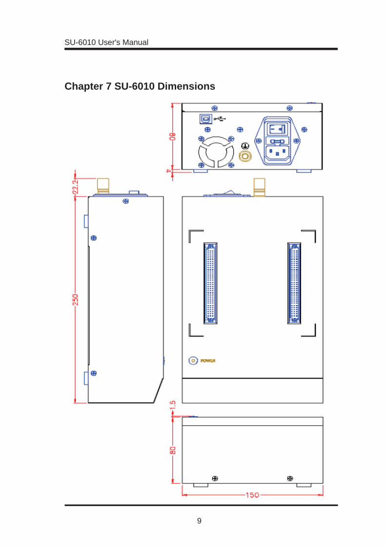
Chapter 7 SU-6010 Dimensions

SU-6010 User's Manual
10
SU-6010 User's Manual
11
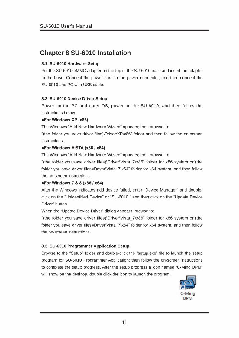
Chapter 8 SU-6010 Installation 8.1 SU-6010 Hardware SetupPut the SU-6010 eMMC adapter on the top of the SU-6010 base and insert the adapter
to the base. Connect the power cord to the power connector, and then connect the
SU-6010 and PC with USB cable.
8.2 SU-6010 Device Driver SetupPower on the PC and enter OS; power on the SU-6010, and then follow the
instructions below.
The Windows “Add New Hardware Wizard” appears; then browse to:
instructions.
The Windows “Add New Hardware Wizard” appears; then browse to:
the on-screen instructions.
After the Windows indicates add device failed, enter “Device Manager” and double-
Driver” button.
When the “Update Device Driver” dialog appears, browse to:
the on-screen instructions.
8.3 SU-6010 Programmer Application Setup
program for SU-6010 Programmer Application; then follow the on-screen instructions
to complete the setup progress. After the setup progress a icon named “C-Ming UPM”
will show on the desktop, double click the icon to launch the program.
SU-6010 User's Manual
12
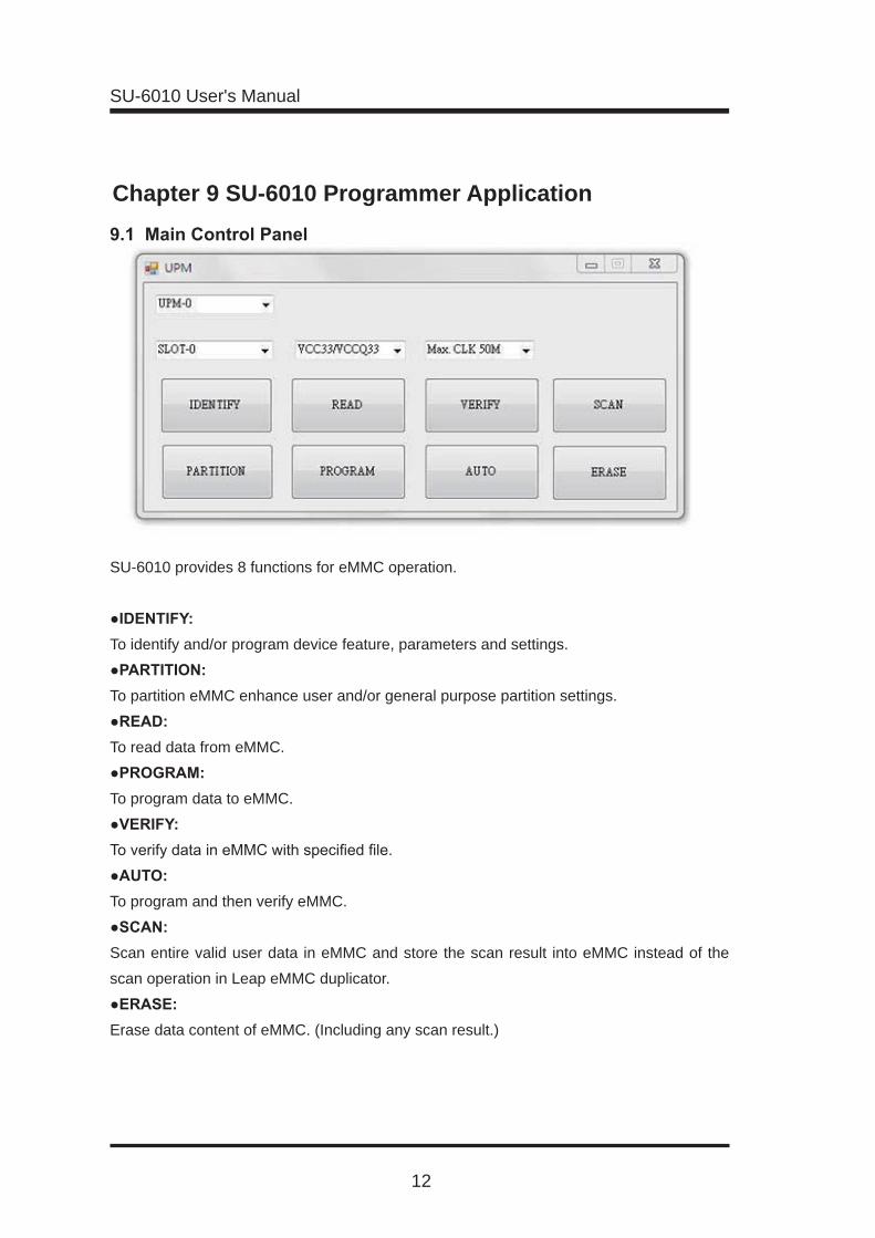
Chapter 9 SU-6010 Programmer Application
SU-6010 provides 8 functions for eMMC operation.
To identify and/or program device feature, parameters and settings.
To partition eMMC enhance user and/or general purpose partition settings.
To read data from eMMC.
To program data to eMMC.
To program and then verify eMMC.
Scan entire valid user data in eMMC and store the scan result into eMMC instead of the
scan operation in Leap eMMC duplicator.
Erase data content of eMMC. (Including any scan result.)

SU-6010 User's Manual
13
1. If there’s more than one SU-6010 connected to PC, you can select which SU-6010 to be controlled here.
2. Select the socket of SU-6010 to be operated; SLOT-0 for eMMC socket and SLOT-
1 for SD/MMC slot.
condition, VCC33/VCCQ33 support and hold a more steady operation, however it
4. Maximum operation clock frequency of SU-6010, it is recommended to select 50M
MMC interface, lower options like 25M/400K may be required to ensure reliability.

SU-6010 User's Manual
14
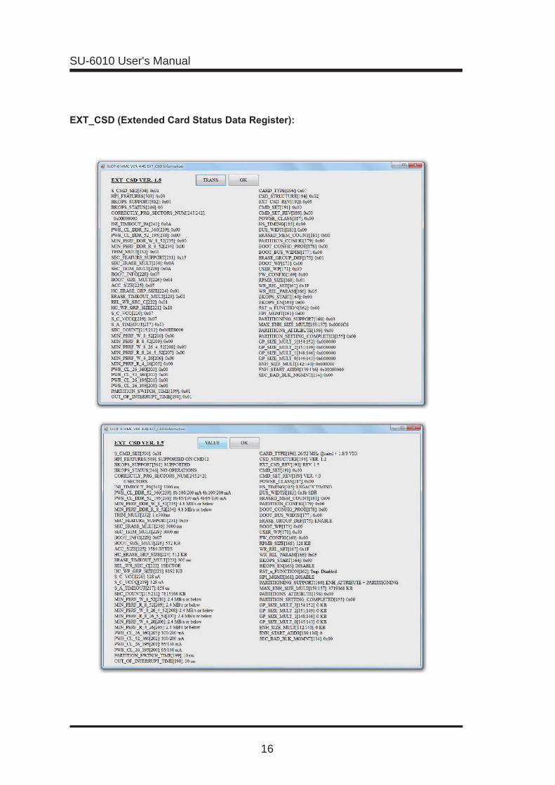
IDENTIFY function is used to identify and retrieve
device feature and parameters including CID,
CSD and EXT_CSD. When displayed, clicking on
“TRANS” button can toggle translation of indicated
parameters.

SU-6010 User's Manual
15
SU-6010 User's Manual
16

SU-6010 User's Manual
17
Parti t ion Sett ing panel is used to
(Please be noted that partit ioning
is a just-for-once and nonreversible
operation for eMMC.)
Indicate current device capacity.
Indicate projected device capacity after
current settings take effect.
Device supported maximum enhanced user size, including user data and general purpose
partitions.
Select +/- button add/reduce unit.
Logical LBA start address setting of enhanced user data area. (Press +/- to add/reduce
setting.)
Enhance user area size setting. (Press +/- to add/reduce setting.)
General purpose partition 1-4 size setting. (Press +/- to add/reduce setting.)
Checked to enable enhance feature of general purpose partition.
For setting register “EXT_CSD[167]”; this register must be set with “EXT_CSD[156]:
PARTITION_SETTING_COMPLETED” simultaneously to take effect, so it have completed
with Partition Setting. This register setting will make eMMC write data with different
method.
“Check” – “1” = Slower write speed, and data can be secured at power fail in the process.
“Uncheck” – “0” = Faster write speed, and data cannot be secured at power fail in the
process.
Check to activate the function of automatically checking the partition settings of eMMC.

SU-6010 User's Manual
18
All 4 operation panel are used in the same
process. READ operation panel is depicted here
as an example.
SU-6010 support 4 proprietary operation mode
also used by Leap eMMC duplicator. Boot 1/2 and
GP 1/2/3/4 are always included in all 4 proprietary
modes.
Operation region determined by MBR partition
table entry.
Operation region includes all device storage
partitions.
AutoScan Mode automatically scan eMMC and record those space occupied by user data.
After that operation region will depend on the user data area recorded as “occupied” in the
scan list.
To access user data partition.
To access BT-1, BT-2, GP-1, GP-2, GP-3 or GP-4 partition.
BT-1, BT-2 and USER_DATA are accessed in sequence. Size of USER_
USER_DATA are accessed, yet aligned to the last sector available.
To start an operation, follow the procedures below:
2. Select preferred operation mode.
3. If suitable, a UserSz text box appears; enter preferred operation region
size (in 100 MB).
4. Click START to begin operation.
Operation will be aborted if encountered any error condition.

SU-6010 User's Manual
19
Chapter 10 SU-6010 Practical Operation
Step 1: Put the eMMC into the socket with correct direction, and then close the socket
cover.
Therefore all the image data, program location,
EXT_CSD , and register settings, can be integrated
SU-6010 User's Manual
20
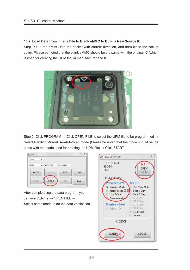
Step 1: Put the eMMC into the socket with correct direction, and then close the socket
cover. Please be noted that the blank eMMC should be the same with the original IC (which
Select Partition/Mirror/User/AutoScan mode (Please be noted that the mode should be the
After completeting the data program, you
SU-6010 User's Manual
21
required in the Appendix 2 is recommended, and also be noted following issues.
Setting the capacity of GP1/2/3/4 and ENHANCE or not; setting the capacity and starting
address of ENHANCE_USER area.
Parameters above can be set through the Partition function of SU-6010. (Please be noted
that this operation is an OTP operation, so please be careful with this function.)
The most common setting is PARTITION_CONFIG setting.
If the settings belong to BOOT_WP and USER_WP, they should be set after data has been
There are data for BOOT-1/2, GP1/2/3/4 (if the size>0), and USER_DATA area.
There are 3 types of image for USER_DATA area: TOP-ALIGN, BOTTOM-ALIGN, and
BOOT-1/2+USER.
TOP-ALIGN image means the data is sequential written from LBA-0; select User Data Only
to perform programming.
BOTTOM-ALIGN image means data is counted from the end of IC’s capacity, backward
Select Bottom to perform programming.
BOOT-1/2+USER image means data is sequential written from LBA-0 of BOOT-1 in IC;
after BOOT-1 is full, data will continue sequential written from LBA-0 of BOOT-2; after
BOOT-2 is full, data will continue sequential written from LBA-0 of USER_DATA area.
Select B1/2+User to perform programming.
4. Program Operation
verify the data. After verify is done, BOOT_WP and USER_WP setting can be performed. (If
it’s necessary to do so)
use. 7.Completing Source IC and Image File Through IDENTIFY and EXT_CSD function to confirm the parameters, and then verify
SU-6010 User's Manual
22
1. Check power cord, power connector, and power plug and see if they’re
loosing.
2. Check power cord and see if it’s well functioned.
3. Check the fuse and see if it’s burnt out.
4. Check power fan and power LED and see if they’re well functioned.
1.2 The System does not show correct device after connecting to PC. 1. Check the power of SU-6010 and see if it’s correct connected and ensure the power
switch is turn ON.
2. Check USB cable and see if it’s correct connected.
3. Check USB cable and see if it’s well functioned.
4. Check device driver and see if it’s correct installed.
1.3 Cannot launch SU-6010 Application. 1. Check the connection of SU-6010 and see if it’s correct connected to PC.
2. Check the power of SU-6010 and see if it’s correct connected and ensure the power
switch is turn ON.
1. Please check all the parameters and settings of eMMC, and see if they’re correct
entered.

SU-6010 User's Manual
23


