T6350-AA-HBK-010 (Rev 4) NSN 0910-LP-105-1685 SUBMARINE GREASING HANDBOOK Naval Sea Systems Command Submarine Hull, Mechanical and Electrical Engineering Management Division (SEA 07T) Distribution Statement D: Distribution authorized to the Department of Defense and DOD contractors only (13 March 2006). This publication contains submarine technical data. Other requests should be referred to the Naval Sea Systems Command (SEA 07T). 13 March 2006
Transcript
T6350-AA-HBK-010 (Rev 4) NSN 0910-LP-105-1685
SUBMARINE GREASING HANDBOOK
Naval Sea Systems Command Submarine Hull, Mechanical and Electrical
Engineering Management Division (SEA 07T)
Distribution Statement D: Distribution authorized to the Department of Defense and DOD contractors only (13 March 2006). This publication contains submarine technical data. Other requests should be referred to the Naval Sea Systems Command (SEA 07T).
13 March 2006
NAVSEA T6350-AA-HBK-010 REV 4
Reproduction for non-military use of the information or illustrations contained in this publication is not permitted. The policy for military use reproduction is established for the Army in AR 380-5, for the Navy and Marine Corps in OPNAVINST 5510.1 series, and for the Air Force in Air Force Regulations 205-1.
LIST OF EFFECTIVE PAGES NOTE: On a changed page, the portion of the text affected by the latest change is indicated by a vertical line, or other change symbol, in the outer margin of the page. Changes to illustrations are indicated by miniature pointing hands. Changes to wiring diagrams are indicated by shaded areas. Total number of pages in this manual is 114 consisting of the following: Page Revision Page Revision No. No. Cover ................. 4 6-1 .................... 4 Title ................. 4 6-2 (Blank) ............ 4A (LOEP)............... 4 A-1 .................... 4 B (BLANK).............. 4 A-2 (Blank) ............ 4 C (CERTIFICATION)...... 4 B-1 thru B-2 ........... 4 D (Blank).............. 4 C-1 .................... 4 E (RECORD OF CHANGES).. 4 C-2 (Blank) ............ 4 F (Blank).............. 4 D-1 thru D-4 ........... 4 G (SUMMARY)............ 4 E-1 .................... 4 H (Blank).............. 4 E-2 (Blank) ............ 4 i thru ix ............. 4 F-1 .................... 4x (Blank) ............. 4 F-2 (Blank) ............ 41-1 thru 1-2 .......... 4 G-1 thru G-3 ........... 42-1 thru 2-33 ......... 4 G-4 (Blank) ............ 42-34 (Blank) .......... 4 H-1 thru H-6 ........... 43-1 thru 3-13 ......... 4 I-1 .................... 43-14 (Blank) .......... 4 I-2 (Blank) ............ 44-1 thru 4-4 .......... 4 I-3 thru I-12 .......... 45-1 ................... 4 J-1 .................... 45-2 (Blank) ........... 4 J-2 (Blank) ............ 4
A
NAVSEA T6350-AA-HBK-010 REV 4
Blank
B
NAVSEA T6350-AA-HBK-010 REV 4
NAVSEA TECHNICAL MANUAL CERTIFICATION SHEET
SUBMARINE GREASING HANDBOOK
NAVSEA 07T
NAVAL SEA SYSTEMS COMMAND
WASHINGTON, D.C. 20376-7031
Technical Direction:
Date
Reviewed By:
Reviewed By:
Approved By:
/ 7f-/u_r
SEA 07T31 (Engineering Section Head) Date
SEA 07T3 (Engineering Branch Head) Date
SEA 07T (Technical Director) Date
NAVSEA T6350-AA-HBK-010 REV 4
Blank
D
NAVSEA T6350-AA-HBK-010 REV 4
RECORD OF CHANGES
Change
No.
Date of
Change Title or Brief Description
Date
Entered
Entered By
(Signature)
E
NAVSEA T6350-AA-HBK-010 REV 4
Blank
F
NAVSEA T6350-AA-HBK-010 REV 4
SUMMARY OF CHANGES INCORPORATED INTO REV 4 The following is an overview of the major changes between REV 3 and REV 4 of the Submarine Greasing Handbook. Chapter 1. The grease isolation valves now have detailed operating procedures in accordance with each associate submarine class. This revision also includes more detail on friction wear and corrosion protection. Chapter 2. Due to the fleet wide changeover from MIL-G-24139 (Multipurpose Water Resistant Grease) to CID-A-A-50433 (Seawater Wash Resistant Grease), MIL-G-24139 is no longer authorized for use on the submarine systems contained in Appendix B. MIL-G-24139 can now only be used for the SEAWOLF Class Retractable Bow Planes Automatic Lubricating System. Grease DOD-G-24508 may now be used on the secondary propulsion motors on board the SSN 21 class and later (prior to this revision it could not be used on any system that came in contact with seawater). Pneumatic grease gun air regulator setpoints have been lowered in this revision. Chapter 3. Trim and drain pump lubrication procedures have been updated to support all submarine classes. Chapter 6. Added the Submarine Lubrication Process Effectiveness Review in this revision. Appendix I. Inclusion of COMSUBLANT Technical Note No. 01-94. In addition to the major changes noted above, administrative changes were made throughout the manual. Such changes include formatting, updating submarine class information, and updating illustrations.
G
NAVSEA T6350-AA-HBK-010 REV 4
Blank
H
NAVSEA T6350-AA-HBK-010 REV 4
TABLE OF CONTENTS
Chapter Page Table of Contents i List of Appendices iii List of Illustrations iv List of Tables iv Safety Summary v Foreword ix General Information 1-1 1.1 Introduction 1-1 1.1.1 Scope 1-1 1.1.2 Purpose 1-1 1.1.3 Applicability 1-1 1.2 Greasing 1-1 1.2.1 Purpose 1-1 1.2.1.1 Friction and Wear 1-1 1.2.1.2 Corrosion Protection 1-2 1.2.2 Systems 1-2 Technical Data 2-1 2.1 Grease Characteristics 2-1 2.1.1 General Purpose Submarine Greases 2-1 2.1.1.1 Commercial Item Description A-A-50433 Seawater Wash Resistant Grease 2-2 2.1.1.2 DOD.G.24508, High Performance Multipurpose Grease 2-2 2.1.2 Grease Application 2-2 2.1.3 Handling and Storage 2-3 2.1.4 Waste Storage and Disposal 2-4 2.2 Grease Pumps 2-4 2.2.1 Pneumatic Grease Pump 2-4 2.2.1.1 Pneumatic Grease Pump equipped with Follower Plate 2-8 2.2.1.2 Low Pressure Air Regulator 2-8 2.2.1.3 Grease Hose 2-8 2.2.1.4 Speedaire Low Pressure Air Relief Valve 2-8 2.2.1.5 Marsh Gauge, 0-5000 psig 2-10 2.2.1.6 Pump Fittings 2-10 2.2.1.7 Determining Quantity of Grease Pumped 2-10 2.2.1.7.1 Basic or Observation Method 2-10 2.2.1.7.2 Spring Scale Method 2-11 2.2.1.8 Maintenance/Care 2-11 2.2.1.8.1 Grease Hose 2-12 2.2.1.8.2 Gauges 2-12
i
NAVSEA T6350-AA-HBK-010 REV 4
TABLE OF CONTENTS (Continued)
Chapter Page 2.2.2 Manual Grease Pump 2-17 2.2.2.1 Type I 2-17 2.2.2.2 Type II 2-17 2.2.2.3 Type III 2-17 2.2.2.4 Type IV 2-17 2.2.2.5 Determining Quantity of Grease Pumped 2-18 2.2.2.5.1 Stroke Method 2-18 2.2.2.5.2 Basic or Observation Method 2-18 2.2.2.6 Maintenance/Care/Handling 2-18 2.3 Fittings 2-20 2.3.1 Lubrication Components 2-20 2.3.1.1 One Notch Grease Fitting 2-20 2.3.1.2 Two Notch Grease Fitting 2-20 2.3.1.3 No Notch Grease Fitting 2-20 2.3.2 Manifold 2-21 2.3.3 Lubrication Distribution Valve 2-21 2.3.4 Lubrication Isolation Valve 2-25 2.3.5 Grease Cup 2-32 2.3.6 Care and Handling 2-32 2.3.6.1 Care and Handling of Grease Fittings 2-32 2.3.6.2 Care and Handling of Grease Cups 2-32 Maintenance 3-1 3.1 Planned Maintenance 3-1 3.1.1 Greasing Schedule 3-1 3.1.2 Planned Maintenance System 3-1 3.1.2.1 Maintenance Requirement Card 3-1 3.1.2.2 Maintenance Index Page 3-1 3.1.2.3 Preventive Maintenance Management Plan 3-1 3.1.2.4 Standard Maintenance Procedures 3-2 3.1.3 Greasing Requirements 3-2 3.1.3.1 Systems Requiring Greasing By Pneumatic Pump 3-2 3.1.3.2 Grease Quantities 3-2 3.1.3.3 Lubrication of Trim and Drain Pumps 3-3 3.1.3.4 Preventive Maintenance Guidelines 3-4 3.2 Corrective Maintenance 3-6 3.2.1 Plugged Grease Fitting 3-6 3.2.2 Grease Lines 3-6 3.2.2.1 Plugged Grease Lines 3-6 3.2.2.2 Loose, Broken or Disconnected Grease Lines 3-6 3.2.2.3 Crimped Grease Lines 3-6 3.2.3 Plugged Grease Manifold 3-7 3.2.4 Plugged Lubrication Distribution Valve 3-7 3.2.5 Plugged Grease Cup 3-7
Appendix Title Page A References A-1 B List of Systems and Cognizant NAVSEA Engineers B-1 C Lubrication Distribution Valve Drawings C-1 D Corrective Procedures D-1 E Lubrication Charts E-1 F Glossary Of Abbreviations and Acronyms F-1 G Testing Requirements For Grease, Seawater Wash Resistant G-1 H Control Surface Noise Troubleshooting Procedure And Questionnaire H-1 I COMSUBLANT TECHNICAL NOTE NO. 01-94, Submarine Lubrication Process Effectiveness Review I-1 J User Comment Form J-1
iii
NAVSEA T6350-AA-HBK-010 REV 4
LIST OF ILLUSTRATIONS
Chapter Title Page 2-1 Typical Grease Pump Functional Relationship 2-5 2-2 Assembled Pneumatic Grease Pump 2-6 2-3 Pneumatic Regulator and Gage 2-9 2-4 Grease Gun with 0-5000 PSIG Gage 2-13 2-5 Correctly Greased Component 2-14 2-6 Correctly Greased Component 2-15 2-7 Correctly Greased Component 2-16 2-8 Manual Grease Pumps 2-19 2-9 Typical Grease Fitting 2-22 2-10 Grease Fittings 2-23 2-11 Grease Manifold 2-24 2-12 SSN 688 Class Lubrication Distribution Valve 2-26 2-13 SSN 688 Class Lubrication Distribution Valve Cutaway View 2-27 2-14 SSN 688 Class Lubrication Distribution Valve Exploded View 2-28 2-15 SSBN/SSGN 726, SSN and SSN 774 Class
Lubrication Distribution Valves 2-29 2-15 SSBN/SSGN 726, SSN and SSN 774 Class
Lubrication Distribution Valves, Exploded View 2-30
2-17 Lubrication Isolation Valve 2-31 3-1 Example of Inadequate Greasing 3-10 3-2 Example of Inadequate Greasing 3-11 3-3 Example of Inadequate Greasing 3-12 3-4 Example of Inadequate Greasing 3-13
LIST OF TABLES
Table Title Page 2-1 40:l Ratio for Pneumatic Grease Pumps 2-7 2-2 50:l Ratio for Pneumatic Grease Pumps 2-7 3-1 Maximum Allowable Grease Pressure for External Grease Fittings 3-2 3-2 MRC Grease Requirement Table Example 3-5 4-1 Supply Data 4-1
iv
NAVSEA T6350-AA-HBK-010 REV 4
SAFETY SUMMARY
The following are general safety precautions that are not related to any specific procedures and therefore do not appear elsewhere in this publication. These are recommended precautions that personnel must understand and apply during many phases of operation and maintenance.
KEEP AWAY FROM LIVE CIRCUITS
Operating personnel must at all times observe all safety regulations. Do not replace components or make adjustments inside the equipment with the high voltage supply turned on. Under certain conditions, dangerous potentials may exist when the power control is in the off position, due to charges retained by capacitors. To avoid casualties, always remove power, discharge and ground a circuit before touching it.
DO NOT SERVICE OR ADJUST EQUIPMENT ALONE
Under no circumstances should any person reach into or enter an enclosure for the purpose of servicing or adjusting the equipment except in the presence of someone who is capable of rendering aid.
RESUSCITATION
Personnel working with or near high voltages should be familiar with modern methods of resuscitation. Such information may be obtained from the ship’s medical representative.
The following warnings and cautions appear in the text of this manual, and are repeated here for emphasis:
WARNING
To avoid fire hazards, rags and absorbents that contain dissimilar or incompatible hazardous waste shall be stored in different containers. (Page 2-3)
WARNING
The pneumatic grease pump delivers grease under high pressure. Improper use may result in serious injury to personnel and damage to equipment. (Page 2-12)
v
NAVSEA T6350-AA-HBK-010 REV 4
CAUTION
Greases MIL-L-15719, MIL-G-6032, and MIL-G-18458 specified in NSTM 262 for general non-nuclear use, are NOT authorized for use on the submarine systems covered in Appendix B (Page 2-2).
CAUTION
Grease DOD-G-24508 greases should not be used on any surface that is exposed to seawater due to their rapid and almost complete washout when exposed to seawater (reference 4). (Page 2-2)
CAUTION
Oil separation from grease, commonly known as bleeding, is characteristic of most greases. The degree of bleeding varies with the composition and storage conditions. A film of free oil does not indicate deteriorated grease. However, when an excessive amount of free oil is present, the grease should not be used unless laboratory analysis confirms that it is within specification requirements. (Page 2-3)
CAUTION
Ensure the correct air relief setpoint is used with the 40:l or 50:l pneumatic grease gun to avoid damage from overpressure. If the pressure ratio of the gun being used is not known, contact the Squadron Material Officer for assistance. (Page 2-4)
CAUTION
Discharge pressure readings to the component being greased could vary by as much as 1000 psig depending on grease pressure gauge location, hose length, obstructions in the hose, kinks, loops or crimps in the hose. It is imperative that the gauge be mounted on or as near as possible to the grease gun nozzle to ensure an accurate reading of grease supply pressure. (Page 2-10)
vi
NAVSEA T6350-AA-HBK-010 REV 4
CAUTION
If grease cannot be seen coming out at the bearing, the grease line should be traced out, hand over hand, to ensure it is not crimped and is properly connected. If the grease line is satisfactory, a higher grease supply pressure may be needed. Caution must be exercised that the maximum allowable pressure for that class submarine listed in Table 3-1 is not exceeded. (Page 2-11)
CAUTION
A manual grease gun can produce pressures as high as 6,000 psig. Use care to ensure that grease lines and the component are not over pressurized. (Page 2-18)
CAUTION
FOR SSN 688 CLASS SHIPS DO NOT OPEN STANDARD GREASE ISOLATION VALVES MORE THAN ONE HALF TURN. Standard lubrication isolation valves are fitted with a stem retaining pin that may be sheared if the valve is forced open one full turn. Six full turns will remove the valve stem. (Page 2-25)
CAUTION
FOR SSBN/SSGN 726, SSN 21 AND 774 CLASS SHIPS, DO NOT OPEN GREASE ISOLATION VALVES WITH PLASTIC OR KNURLED METAL HAND WHEELS MORE THAN ONE AND ONE HALF (1 1/2) TURNS. Grease isolation valves operated with a 9/16" socket wrench should not be opened more than three turns. (Page 2-25)
CAUTION
A grease pump should not be used to lubricate motor or generator ball bearings because over greasing can cause premature bearing failure. (Page 2-32)
vii
NAVSEA T6350-AA-HBK-010 REV 4
CAUTION
All grease lines subjected to line pressure of 4000 psig or higher should be visually inspected for integrity after greasing or during the next scheduled drydocking. (Page 3-3)
CAUTION
DOD-G-24508 and MIL-G-24139 greases are not suitable for trim and drain pump lower bearings. (Page 3-3)
CAUTION
CID A-A-50433 is not suitable for the trim and drain pump upper pump bearing. (Page 3-3)
CAUTION
The use of grease at pressures higher than recommended may damage equipment not intended to be subjected to these pressures. Before increasing grease pressure, determine the maximum allowed grease pressure identified in Table 3-1 and contact the Squadron Material Officer. (Page 3-6)
viii
NAVSEA T6350-AA-HBK-010 REV 4
FOREWORD
The submarine fleet completed a changeover from MIL-G-24139 (General Purpose) grease to Commercial Item Description (CID) A-A-50433 (TERMALENE #2). Currently, TERMALENE #2 is the only grease authorized for systems exposed to seawater, with the exception of the SEAWOLF Class Retractable Bow Planes Automatic Lubricating System. A submarine’s load-out of TERMALENE #2 grease is more than sufficient to grease a bearing or two while underway, but the load out is not sufficient to perform the quarterly greasing Maintenance Requirement Cards (MRCs). All greasing MRCs should be performed inport. Proper greasing is required for preservation of all lubricated equipment.
Typically junior sailors are assigned the task of performing the greasing MRCs, without any formal training. This handbook should be read and understood by all persons performing greasing MRCs. By reading this handbook, the person performing the greasing will better understand the greasing requirements, be familiar with different the lubrication equipment, and identify any problems that may arise.
Equipment and machinery failures experienced on submarines are often due to excessive bearing wear or bearing failure. In most cases the cause of the bearing wear or failure is lack of proper lubrication. This handbook is a compilation of information on grease and greasing equipment used for general non-nuclear lubrication on submarines. The information was obtained from manufacturers, technical manuals, and Navy documents. It also contains information based on the experience of fleet personnel and Naval Sea Systems Command engineers. This handbook is intended to supplement rather than replace existing planned maintenance system requirements, preventive maintenance management plan, standard maintenance procedures, technical manuals, and the guidance of the Naval Ships Technical Manual. Appendix J provides user comment forms which may be used to forward pertinent data that may improve this handbook. Attach any additional papers to the comment form, place in an envelope, and address to the following activity: SEA07T31 NAVAL SEA SYSTEMS COMMAND WASHINGTON NAVY YARD
ix
NAVSEA T6350-AA-HBK-010 REV 4
Blank
x
NAVSEA T6350-AA-HBK-010 REV 4
CHAPTER 1
GENERAL INFORMATION
1.1 Introduction
1.1.1 Scope This handbook addresses the greases approved for general non-nuclear use on submarine systems, the grease pumps and grease fittings used to apply the lubrication, and the greasing of the majority of non-nuclear submarine systems. This handbook also covers the care and handling procedures for grease, grease guns, and grease fittings used aboard submarines.
1.1.2 Purpose The purpose of this handbook is to provide relevant information and assist those involved in greasing submarine equipment. It discusses the types of equipment used, operating procedures, and the types of grease authorized for use in submarine systems.
1.1.3 Applicability This handbook applies to all classes of submarines and is to supplement existing manuals. Should any conflict in procedures or requirements arise, the ranking of Planned Maintenance System/Maintenance Requirement Cards (PMS/MRC), or Preventive Maintenance Management Plan/ Standard Maintenance Procedures (PMMP/SMP) as applicable, Equipment Technical Manual, Naval Ships Technical Manual (NSTM), and Submarine Greasing Handbook will be followed. All conflicts should be brought to the attention of the cognizant life cycle manager at Naval Sea Systems Command (Appendix B).
1.2 Greasing
1.2.1 Purpose Greases are typically used in situations where sufficient lube oil cannot be effectively maintained on machinery surfaces, or when a simplistic lubricating system is desired or required. The basic functions of grease are to reduce friction and wear, dissipate heat, and prevent corrosion. Grease conducts friction-generated heat away from bearings, acts as a seal to protect areas from contamination, and acts as a carrier for materials such as rust preventives, anti-friction agents, and extreme pressure additives.
1.2.1.1 Friction and Wear The surfaces of machinery components appear well-finished to the naked eye. When magnified, however, surface imperfections become readily apparent. These microscopic hills and valleys are called asperities. When dry surfaces move relative to one another, asperities may rub, lock
1-1
NAVSEA T6350-AA-HBK-010 REV 4
together, and break apart. The resistance generated when these adjacent surfaces come in contact is called friction. The welding together and breaking apart of asperities is a form of adhesive wear. Another form of wear may occur when a hard contaminant particle becomes trapped between two opposing surfaces. When this occurs, the contaminant acts as a miniature lathe, cutting into the softer machinery surface. This process is termed abrasive wear. Another consequence of friction is that the energy created by resistance is converted into heat. The primary functions of a lubricant, then, are the formation of a protective film between adjacent surfaces to reduce wear, and the dissipation of heat generated at these wear surfaces.
1.2.1.2 Corrosion Protection A second role provided by a lubricant is the prevention of system corrosion. In environments where contamination of the system with water is likely, protection of machinery components from corrosion is of the utmost importance. Salt water is considerably more corrosive than fresh water; thus Naval machinery must be well protected from this contaminant. Water molecules may also diffuse through the lubricant and enter surface microcracks, causing hydrogen embrittlement and subsequent surface failure. It is imperative that water contamination of machinery systems be minimized. To achieve corrosion protection, lubricants must form a protective barrier on machinery surfaces. Modern-day lubricants often contain corrosion inhibitors which chemically bond to the metallic surfaces of equipment components. Corrosion inhibitors are an example of a class of compounds called additives.
1.2.2 Systems This manual is intended to aid the user in properly lubricating most non-nuclear systems found aboard today’s submarines. Systems for which this manual was specifically developed, and their associated NAVSEA life cycle manager and SEA 07T cognizant engineering branch are presented in Appendix B.
1-2
NAVSEA T6350-AA-HBK-010 REV 4
CHAPTER 2
TECHNICAL DATA
2.1 Grease Characteristics
Greases essentially consist of a semisolid mixture of oil and thickening agent. The oil may be either petroleum or synthetic base. Thickening agents are typically alkali soaps or clay (bentonite) materials. Critical grease properties, such as hardness and water washout, are dependent on the selection of base oil and thickening agent. Greases are also used when the part cannot be lubricated often or is not accessible during operation. Most greases are made up of four parts:
a. Fluid base (usually mineral oil). b. Thickener (usually a soap). c. Additives (chemical compounds that change the grease’s
properties). d. Fillers (such as graphite which make the grease more
stable).
Most of the properties of a grease come from the fluid base and the thickener.
2.1.1 General Purpose Submarine Greases Government specifications identify and describe the characteristics and requirements of lubricants used to grease shipboard equipment. There are five types of greases approved by the Naval Ships Technical Manual (NSTM), Chapter 262 (reference 1) for general non-nuclear use. These greases are:
(a) General Purpose Grease Seawater Wash Resistant - CID A-A-50433, and MIL-G-24139
(b) High Performance, Multipurpose Grease - DOD-G-24508, (c) Plug Valve, Gasoline and Oil Resistant Grease - MIL-G-
6032, (d) Lubricating Grease (High Temperature, Electric Motor,
Greases authorized for naval nuclear propulsion plant equipment and associated piping systems are listed in NAVSEA Instruction 9210.41 (reference 2).
2-1
NAVSEA T6350-AA-HBK-010 REV 4
CAUTION
Greases MIL-L-15719, MIL-G-6032, and MIL-G-18458 specified in NSTM 262 for general non-nuclear use are NOT authorized for use on submarine systems covered in Appendix B.
2.1.1.1 Commercial Item Description A-A-50433 Seawater Wash Resistant Grease Grease supplied by Commercial Item Description (CID) A-A-50433 “Seawater Wash Resistant Grease” has replaced MIL-G-24139, Multipurpose, Water Resistant Grease. MIL-G-24139 is only authorized for use on submarines for the SEAWOLF Class Retractable Bow Planes Automatic Lubricating System.
CID A-A-50433 grease shall be used on all submarine systems where MIL-G-24139 was previously required, and as further defined by Naval Sea Systems Command (reference 3). CID A-A-50433 grease is a seawater washout resistant grease used for bearing and sliding surface lubrication for temperatures up to 350ºF. This grease is not suitable for high speed roller or ball bearings.
CAUTION
DOD-G-24508 grease should not be used on any surface that is exposed to seawater due to rapid and almost complete washout when exposed to seawater (reference 4).
2.1.1.2 DOD-G-24508, High Performance Multipurpose Grease This is a high performance ball and roller bearing grease used to lubricate equipment operating from room temperature to 300°F, and, for four hours out of every twenty four hours, up to 350°F. This grease is also used in other high temperature applications such as steam turbine control valves. This grease is NOT authorized for use in seawater systems or components subject to exposure to seawater, with the exception of the Secondary Propulsion Motor (SPM) on SSN 21 Class and later ships.
2.1.2 Grease Application Grease may be applied through grease cups or through hydraulic lubrication fittings. Hydraulic lubrication fittings form a readily installed and convenient means for lubricating numerous low-speed, lightly loaded, or widely separated bearings. These fittings are not acceptable for use on electric motors or generators because of the danger of grease being forced out of the bearing and onto windings. A grease gun or other pressure device shall be used for applying grease through hydraulic type fittings (grease lines). When
2-2
NAVSEA T6350-AA-HBK-010 REV 4
grease is applied through hydraulic lubrication fittings, pressure should be applied until grease seeps out around the full edge of the bearings. If not, the bearing will fail due to a lack of lubrication. Some components require cycling during the greasing process. Refer to the applicable Maintenance Requirement Card (MRC) for specific operating instructions while greasing. In bearings fitted with felt or other seals, care shall be exercised to avoid breaking the seals by the application of too much pressure. The type of fitting should be identified and carbon steel fittings which are corroded should be replaced with Corrosion Resistant Steel (CRES) or Monel fittings.
CAUTION
Oil separation from grease, commonly known as bleeding, is characteristic of most greases. The degree of bleeding varies with the composition and storage conditions. A film of free oil does indicate deteriorated grease. However, when an excessive amount of free oil is present, the grease should not be used unless laboratory analysis confirms that it is within specification requirements.
2.1.3 Handling and Storage The effects of overheating, insufficient ventilation, and proximity to dangerous materials must be considered when handling and storing lubricants. Careless handling may lead to damage, such as opening of container seams. Leakage from open container seams increases fire safety hazards. Leakage may also lead to contamination or deterioration of the lubricant. The deterioration of grease is usually indicated by excessive bleeding or a change in texture. Although neither condition indicates that the grease is beyond the specification limits, tests such as penetration, dropping point and oil separation should be conducted to make a final determination. Good housekeeping in handling and storage areas should be followed at all times. A temperature range of 40°F to 80ºF is the most desirable for storage.
WARNING
To avoid fire hazards, rags and absorbents that contain dissimilar or incompatible hazardous waste shall be stored in different containers.
2.1.4 Waste Storage and Disposal Items such as rags, mop heads, and absorbents used to clean up grease spills must
2-3
NAVSEA T6350-AA-HBK-010 REV 4
themselves be treated as grease waste. Containerize waste in original container, if possible, or use standard container as listed in the Naval Ships Technical Manual, S9086–T8–STM-010/CH-593 Chapter 593, Pollution Control. In accordance with OPNAVINST 5100.19D mark the container with a DoD Hazardous Chemical Warning Label, DD Form 2521 (8-1/2" x 11") NSN 0102-LF-012-0800, or DoD Form 2522 (4" x 7") NSN 0102-LF-012-1100. Store for shore disposal according to DoD 6050.5-LR, “DoD Hazardous Materials Information System Hazardous Item Listing”, which is more commonly identified as HMC&M/HMIS CD-ROM system. This system includes the Hazardous Materials User's Guide (HMUG), which provides instructions on the disposal of grease.
2.2 Grease Pumps
Grease pumps provide grease at regulated pressure for injecting grease into hydraulic lubrication fittings. There are two common types of grease pumps used: pneumatic and manual.
2.2.1 Pneumatic Grease Pumps Pneumatic grease pumps deliver large amounts of grease at a known pressure over a given time due to the automatic pumping action. The pneumatic grease pump delivers only a small amount of grease with each cycle. It takes a large number of strokes to deliver any substantial quantity of grease. As a minimum, the grease pump must be capable of developing 4000 psig grease discharge pressure with a 100 psig air supply. There are several manufacturers supplying pneumatic grease pumps to the Navy through the national stock system. The functional relationship and configuration of a pneumatic grease pump is presented in Figure 2-1. A photograph of an assembled pneumatic grease pump is shown in Figure 2-2. The parts comprising a pneumatic grease pump are discussed in the following paragraphs.
CAUTION
Ensure the correct air relief set point is used with the 40:l or 50:l pneumatic grease gun to avoid ship system damage from over pressure. If the pressure ratio of the gun being used is not known, contact the Squadron Material Officer for assistance.
Pneumatic grease pump procured through the national stock system will be rated at a minimum of 40:1 and a maximum of 50:1 pressure ratio depending on the specific model pump procured. Grease discharge pressure is directly proportional to the regulated air supply pressure and pump pressure ratio. A pump
2-4
NAVSEA T6350-AA-HBK-010 REV 4
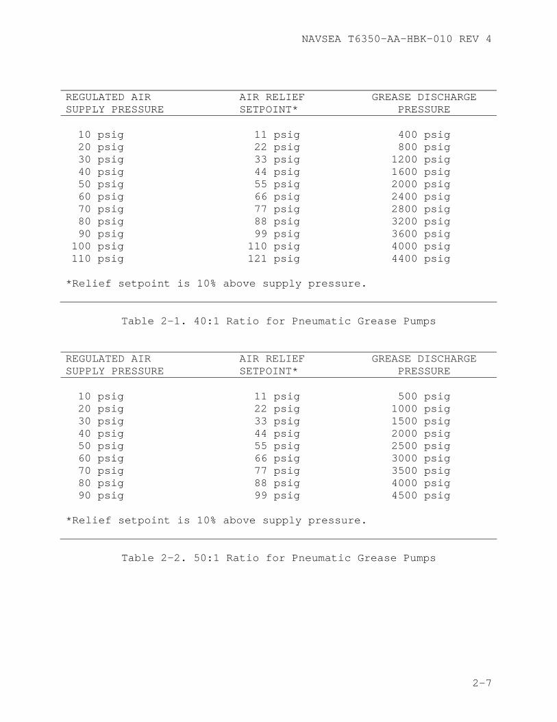
with a 40:1 pressure ratio requires inlet pressure regulated to no greater than 50 psig to develop 2000 psig grease discharge pressures. Table 2-1 lists the air relief valve set points and expected discharge pressures of the grease for a 40:1 pressure rated pneumatic grease pump. Table 2-2 presents the same information for a 50:l pressure rated pneumatic grease pump.
2.2.1.1 Pneumatic Grease Pump Equipped with Follower Plate The pneumatic pump and follower plate come as a unit. The follower plate is designed to provide a positive pressure on the grease in the can to prevent air-binding of the pump. Experience with this type of pump has shown that artificially weighting the follower plate with a TDU weight, drilled to fit around the pump housing, greatly enhances the ability of the follower plate to prevent pump air-binding.
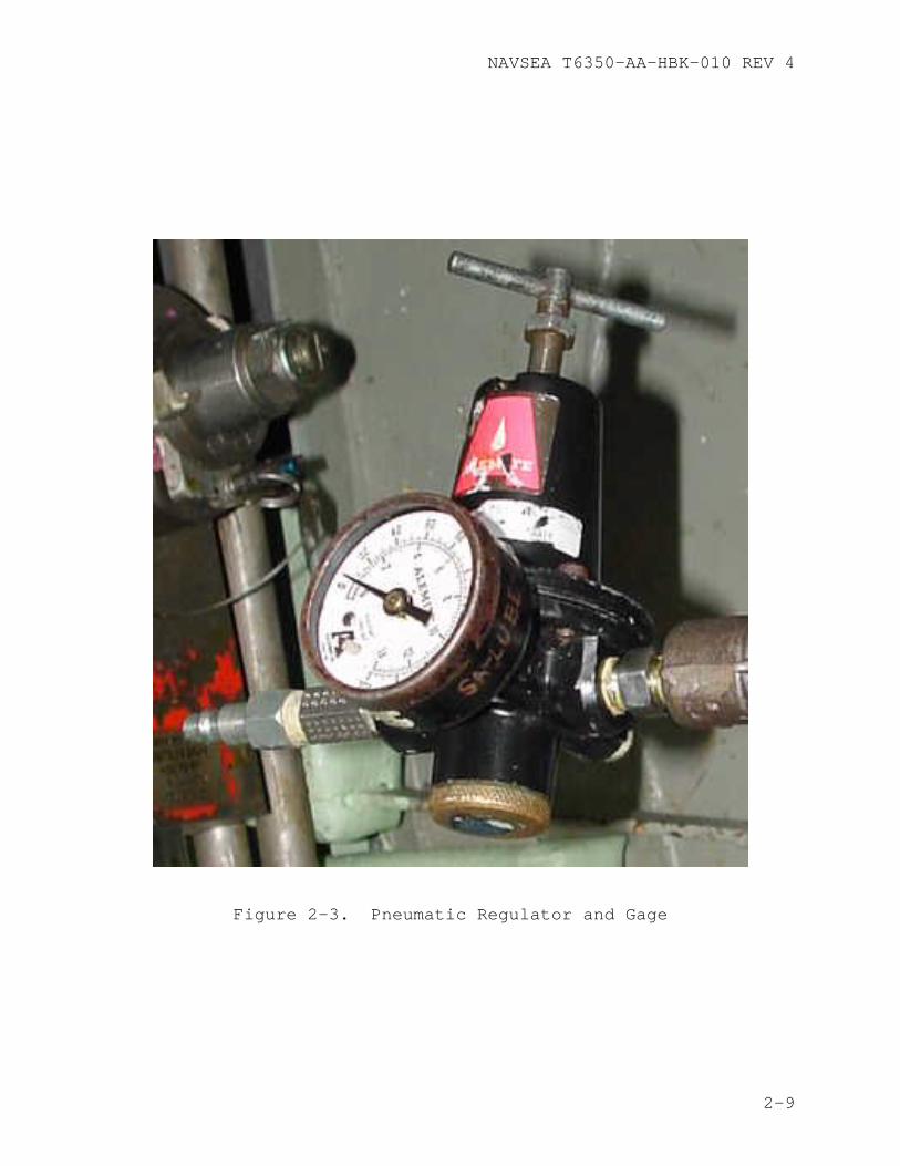
2.2.1.2 Low Pressure Air Regulator The low pressure air regulator is a balanced valve type air regulator which maintains a constant pressure to prevent erratic operation. A relief feature vents off excess pressure when adjusted to a lower air pressure. The regulator has an operating range of 0 to 125 psig with a maximum air input pressure of 250 psig. The regulator has strainers to prevent foreign matter from entering the air line. The low pressure air regulator includes an air pressure gauge with a range of 0 to 160 psig. The low pressure air regulator is shown in Figure 2-3. The national stock system may substitute regulators or gauges which are rated equal to or better than that described in this paragraph. Ensure the regulator is equipped with a gage when received from the supply system.
2.2.1.3 Grease Hose The recommended length of the grease hose is 50 feet. The hose should be rated for a maximum working pressure of 5000 psig and a minimum burst pressure of 20,000 psig. When conducting initial loading or complete change out of grease in a component which requires more than five pounds, a grease hose length of 10 to 12 feet is recommended to speed up the loading rate.
2.2.1.4 Speedaire Low Pressure Air Relief Valve The Speedaire low pressure air relief valve provides protection on the air input side of the pneumatic grease pump. If the air pressure goes above the relief valve setpoint, the relief valve will vent the excessive pressure, preventing overpressure damage to grease lines, fittings, and components being greased.
2-8
NAVSEA T6350-AA-HBK-010 REV 4
Figure 2-3. Pneumatic Regulator and Gage
2-9
NAVSEA T6350-AA-HBK-010 REV 4
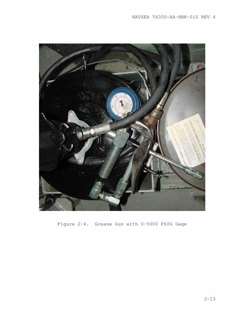
2.2.1.5 Marsh Gauge, 0-5000 psig 2 1/2” dial, single bourdon tube, shatterproof face plate, rubber encapsulated. The 0-5000 psig gauge is shown in Figure 2-4. The 0-5000 psig pressure gauge is connected to the inlet of the grease gun and measures the grease pressure supplied to the component being greased.
CAUTION
Discharge pressure readings to the component being greased could vary by as much as 1000 psig depending on gauge location, hose length, obstructions in the hose, kinks, loops or crimps in the hose. It is imperative that the gauge be mounted on or as near as possible to the grease gun nozzle to ensure an accurate reading of grease supply pressure.
2.2.1.6 Pump Fittings The pneumatic grease pump uses various pipe nipples, pipe tees, pipe plugs, and service air quick disconnects. These fittings are ordered through the supply system (Table 4-1).
2.2.1.7 Determining Quantity of Grease Pumped The amount of grease pumped to the submarine components by a pneumatic grease pump is determined by one of the following methods:
a. Basic or Observation Method b. Spring Scale Method
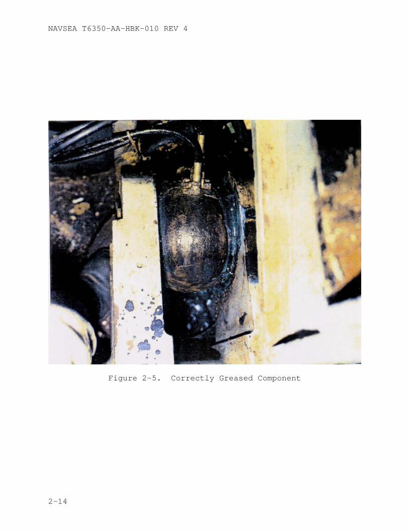
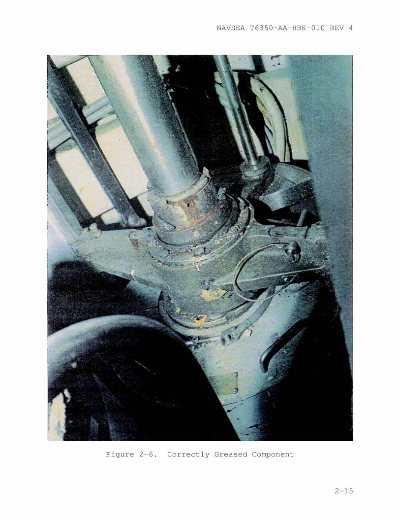
2.2.1.7.1 Basic or Observation Method The basic or observation method of greasing ensures that an adequate amount of grease is supplied to a component based on observation. The quantity of grease is sufficient when grease appears at the component joint. This is the most foolproof and preferred method of ensuring that a component has been properly greased. An example is a bearing where grease should exit 360º around and on both ends of the bearing (Figures 2-5 through 2-7). Some components have grease seals that do not allow grease to escape unless the seals fail. For bearings with seals, back pressure in the grease pump must be closely monitored. Any indication of an increase in back pressure would indicate that the component is sufficiently lubricated. Seal failure could occur if pumping is not stopped as soon as an increase in back pressure is observed. Typically components with grease seals are not lubricated with grease pumps, pneumatic or manual. On some joints, such as reach rods with universal joints, the joint is enclosed in a rubber or leather boot. When the boot begins to swell, the joint has
2-10
NAVSEA T6350-AA-HBK-010 REV 4
enough grease. When greasing components external to the pressure hull, the best way to determine that the proper amount of grease is supplied is the observation method. When in drydock, the spring scale method should be used in conjunction with the observation method, the ship can verify the quantity of grease that a particular bearing needs when waterborne. Have two men in direct communication with each other, one inboard greasing the fitting and the other outboard observing the component. When the bearing is observed to have a sufficient amount of grease, the observer informs the pump operator. The amount of grease used per component should be documented and compared to the MRC to ensure the MRC is correct. This check also ascertains that the grease lines are properly connected, functioning and labeled.
CAUTION
If grease cannot be seen coming out at the bearing, the grease line should be traced out, hand over hand, to ensure it is not crimped and is properly connected. If the grease line is satisfactory, a higher grease supply pressure may be needed. Caution must be exercised that the maximum allowable pressure for that class submarine listed in Table 3-1 is not exceeded.
2.2.1.7.2 Spring Scale Method The spring scale method of greasing ensures that the correct amount of grease is applied to the component by weighing the grease container and grease pump. The grease gun is first operated to ensure that the discharge line is filled with grease. The grease pump and grease container are then weighed prior to and during greasing to monitor the amount of grease being applied to the component. This is the only method that can be used for determining the quantity of grease pumped to bearings when the grease cannot be seen emerging from the bearing.
When in drydock, if the spring scale method is used in conjunction with the observation method, the ship can verify the quantity of grease that a particular bearing needs when waterborne. Refer to the appropriate MRC or SMP for detailed procedures.
2.2.1.8 Maintenance/Care Before using a pneumatic grease pump, perform a visual inspection of the grease hose and gauges.
2-11
NAVSEA T6350-AA-HBK-010 REV 4
WARNING
The pneumatic grease pump delivers grease under high pressure. Improper use may result in serious injury to personnel and damage to equipment.
2.2.1.8.1 Grease Hose Inspect the grease hose for cuts, nicks, or tears, and check the quick disconnects on both ends of the grease hose for damage. If any damage is found, replace the grease hose or quick disconnects.
2.2.1.8.2 Gauges Inspect the low and high pressure gauges and replace if any damage is found. Verify that both gauges have current calibration tags. If a gauge does not have a current calibration tag, have the gauge recalibrated or replaced.
2-12
NAVSEA T6350-AA-HBK-010 REV 4
Figure 2-4. Grease Gun with 0-5000 PSIG Gage
2-13
NAVSEA T6350-AA-HBK-010 REV 4
Figure 2-5. Correctly Greased Component
2-14
NAVSEA T6350-AA-HBK-010 REV 4
Figure 2-6. Correctly Greased Component
2-15
NAVSEA T6350-AA-HBK-010 REV 4
Figure 2-7. Correctly Greased Component
2-16
NAVSEA T6350-AA-HBK-010 REV 4
CAUTION
A manual grease pump can produce pressures as high as 6,000 psig. Use care to ensure that grease lines and the component are not over pressurized.
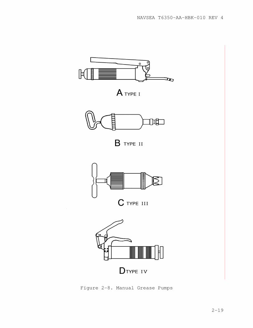
2.2.2 Manual Grease Pump Manual grease pumps are operated by hand and are used on components that require small quantities of grease. There are four types of manual grease pumps: Type I (lever operated), Type II (push operated), Type II (screw operated), and Type IV (pistol grip).
NOTE
Type I and Type IV manual grease pumps are the two most commonly used on submarines.
2.2.2.1 Type I The Type I lever operated manual grease pump is available in three sizes: 14, 18 and 80 ounce capacities. The discharge rate is 1 ounce per 40 strokes at 0 psig back pressure and 0.8 ounce per 40 strokes at 3000 psig back pressure with a maximum discharge pressure of 6,000 psig. A Type I lever operated manual grease pump is shown in Figure 2-8, detail A.
2.2.2.2 Type II The Type II push operated manual grease pump is available in three sizes: 3, 10 and 28 ounce capacities. The 3 ounce grease pump has a discharge rate of 0.75 ounce per 150 strokes at 0 psig back pressure and 0.24 ounce per 50 strokes at 3000 psig back pressure with a maximum discharge pressure of 4000 psig. The 10 and 28 ounce grease pumps have a discharge rate of 0.24 ounce per 509 strokes at 3000 psig back pressure. The 10 and 28 ounce pumps have a maximum discharge pressure of 4300 psig. A Type II push operated manual grease pump is shown in Figure 2-8, detail B.
2.2.2.3 Type III The Type III screw operated manual grease pump has an 8 ounce capacity, with a maximum discharge pressure of 500 psig. A Type III Screw-Operated manual grease pump is shown in Figure 2-8, detail C.
2.2.2.4 Type IV The Type IV pistol grip manual grease pump is available in three sizes: 3, 14 and 16 ounce capacities. The 3 ounce grease pump has a discharge rate of 0.8 ounce per 40 strokes at 0 psig back pressure and 0.5 ounce per 40 strokes at 3000 psig back pressure. The 14 and 16 ounce grease pumps have a discharge rate of 1 ounce per 40 strokes at 0 psig back pressure and 0.8 ounce per 40 strokes at 3000 psig back
2-17
NAVSEA T6350-AA-HBK-010 REV 4
pressure. The Type IV pistol grip manual grease pump is shown in Figure 2-8, detail D.
2.2.2.5 Determining Quantity of Grease Pumped The amount of grease pumped by the four types of manual grease pumps is determined by one of the following methods:
a. Stroke Method b. Basic or Observation Method
2.2.2.5.1 Stroke Method The Stroke Method is the primary method used with manual grease pumps to estimate the amount of grease pumped. The stroke method estimates the amount of grease pumped based on the number of strokes taken. For example, a lever operated grease pump supplies 1 ounce of grease per 40 strokes. To calculate how many strokes are required to grease a component requiring 10 ounces of grease, multiply 10 ounces by 40 strokes per ounce. This shows that 400 strokes (10 X 40 = 400) are required to pump 10 ounces of grease.
2.2.2.5.2 Basic or Observation Method Refer to paragraph 2.2.1.7.1.
2.2.2.6 Maintenance/Care/Handling Manual grease pumps should normally be used with only one type of grease. If the grease pump is to be used with a different type of grease, the following procedure must be followed to prevent contamination:
a. Remove the pump head from the grease pump body. b. Using a scribe, stiff wire, or similar tool, remove as
much of the old grease as possible from the pump body, nozzle, and nozzle head.
c. Using hot soapy water, clean the remaining old grease from the pump body, nozzle, and nozzle head.
d. Dry the grease pump components and fill the pump with the desired grease.
e. Reassemble the grease pump. f. Discharge the grease pump into a container. Check the
flow of grease discharging from the nozzle head for evidence of the original grease or water. If any evidence of contamination is found, continue pumping until contamination is no longer evident.
2-18
NAVSEA T6350-AA-HBK-010 REV 4
Figure 2-8. Manual Grease Pumps
2-19
NAVSEA T6350-AA-HBK-010 REV 4
2.3 Fittings
Grease is applied to submarine components through grease fittings, manifolds, lubrication distribution valves, or grease cups.
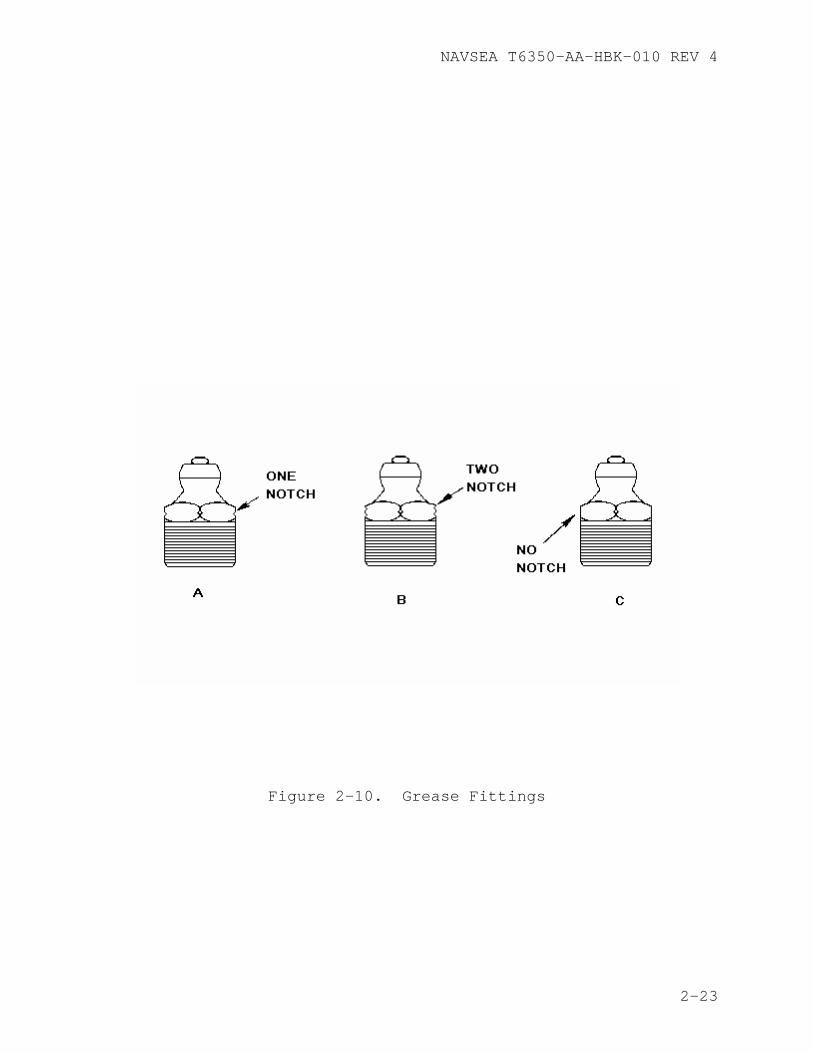
2.3.1 Lubrication Components A grease fitting is a spring loaded ball check valve (Figure-2-9) which is normally closed to prevent the entrance of foreign matter. Grease fittings provide an easily installed and convenient means for lubricating low-speed, lightly loaded, or widely separated bearings. Grease fittings are not used on electric generators and motors due to the danger of grease being forced out of the bearings onto motor windings. Grease fittings are designed with either straight or tapered (pipe) threads and are fabricated primarily from carbon steel or nickel-copper alloy (monel). Applicable NAVSEA drawings should be used to determine the correct grease fitting for a given system. There are three types of grease fittings used aboard submarines (reference 1) that are distinguished by notches, or the absence of notches, on the head of the grease fitting. Two common grease fitting failure modes are plugged and leaking ball check valves, repaired by replacing the grease fitting. If grease back pressure at a fitting goes very high as soon as you start to pump and the hull stop valve is open, replace the fitting. If after replacing the grease fitting the back pressure acts as before, the grease line is probably crimped or plugged. If after applying grease to a fitting and wiping it clean grease reappears on the fitting, the fitting ball check valve did not seat, which is sometimes corrected by lightly tapping the fitting.
2.3.1.1 One Notch Grease Fitting The one notch grease fitting is constructed of nickel-copper alloy (monel) and is used in equipment and machinery exposed to weather, seawater systems and in spaces having high humidity. The one notch grease fitting is shown in Figure 2-10, detail A.
2.3.1.2 Two Notch Grease Fitting The two notch grease fitting is constructed of corrosion resistant steel (CRES). If allowed by applicable NAVSEA system drawings, CRES fittings may be used if monel fittings are not unavailable. The two notch grease fitting is shown in Figure 2-10, detail B.
2.3.1.3 No Notch Grease Fitting The no notch grease fitting is constructed of carbon steel and is used in equipment and machinery not exposed to weather nor in spaces having high humidity. Any no notch fitting that is corroded or causing
2-20
NAVSEA T6350-AA-HBK-010 REV 4
problems during greasing should be replaced with a monel or CRES fitting (preferably monel). The no notch grease fitting is shown in Figure 2-10, detail C. Although not specifically prohibited from use on board submarines (reference 1), use of these fittings should be minimized or eliminated due to the potential for rapid corrosion and deterioration.
2.3.2 Manifold A grease manifold consists of a metal plate with a number of grease fittings, each connected to its own line. Grease manifolds should have specific operating instructions, either on the Equipment Guide List (EGL) or posted nearby. To ensure the correct component is selected, a plate should be posted on or near the manifold specifying which component is served by which fitting. A grease manifold is shown in Figure 2-11. Incorrectly identified grease fittings on the manifold pose a major problem. When conditions permit, a visual inspection should be made to ensure grease is going to the component specified at the manifold. Do not open grease isolation valves with plastic or knurled metal handrails more than 1-1/2 turns or open until back pressure is felt indicating retaining pin has been reached. Grease isolation valves operated with 9/16” socket wrench should not be opened more than 3 turns or until back pressure is felt indicating stop plate has been reached.
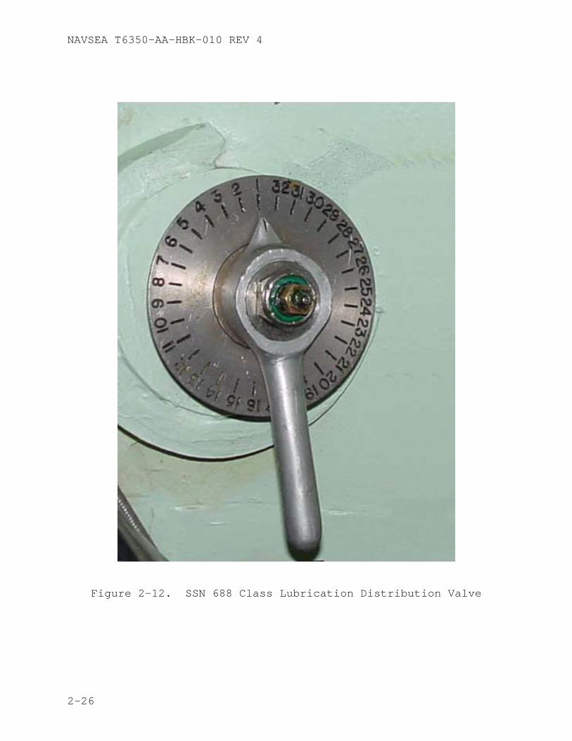
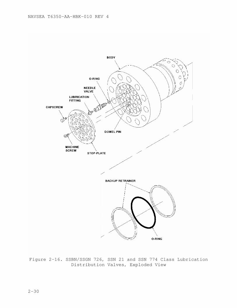
2.3.3 Lubrication Distribution Valve The SSN 688 Class lubrication distribution valve uses one grease fitting to supply grease to each of the grease lines connected to the distribution valve. The SSBN/SSGN 726, SSN 21 and SSN 774 Classes use a slightly different arrangement for distribution in that each line on the grease distribution valve has its own grease fitting. A typical SSN 688 Class lubrication distribution valve is shown in Figure 2-12. Figure 2-13 shows a cutaway view of the SSN 688 Class lubrication distribution valve and Figure 2-14 shows an exploded view. A typical SSBN/SSGN 726, SSN 21 and SSN 774 Class lubrication distribution valve is shown in Figure 2-15. Figure 2-16 shows an exploded view of the SSBN/SSGN 726, SSN 21 and SSN 774 Class lubrication distribution valve. The NAVSEA drawing numbers for the lubrication distribution valves are listed in Appendix C. There are two common problems associated with lubrication distribution valves: incorrect position identification, and misalignment of the valve body and valve rotor (SSN 688 Class). Both problems prevent grease from getting to a component. When conditions permit, a visual inspection should be made to ensure grease is going to the component specified at the valve position indicator, as discussed in paragraph 2.2.1.7.1.
2-21
NAVSEA T6350-AA-HBK-010 REV 4
Figure 2-9. Typical Grease Fitting
2-22
NAVSEA T6350-AA-HBK-010 REV 4
Figure 2-10. Grease Fittings
2-23
NAVSEA T6350-AA-HBK-010 REV 4
Figure 2-11. Grease Manifold
2-24
NAVSEA T6350-AA-HBK-010 REV 4
CAUTION
FOR SSN 688 CLASS SHIPS, DO NOT OPEN STANDARD GREASE ISOLATION VALVES MORE THAN ONE HALF TURN. Standard lubrication isolation valves are fitted with a stem retaining pin that may be sheared if the valve is forced open one full turn. Six full turns will remove the valve stem.
CAUTION
FOR SSBN/SSGN 726, SSN 21 AND 774 CLASS SHIPS, DO NOT OPEN GREASE ISOLATION VALVES WITH PLASTIC OR KNURLED METAL HAND WHEELS MORE THAN ONE AND ONE HALF (1-1/2) TURNS. Grease isolation valves operated with a 9/16” socket wrench should not be opened more than three turns.
2.3.4 Lubrication Isolation Valve Several components external to the hull are lubricated from lines which are not associated with a distribution valve. These individual lines have hull stop valves which are used to isolate the component when not being greased. A lubrication isolation valve is shown in Figure 2-17. One of the most common problems with this configuration is failure of the maintenance person to open the isolation valve, resulting in high grease pressures and failure of the grease to get to the component being greased. Do not open grease isolation valves with plastic or knurled metal handrails more than 1-1/2 turns or open until back pressure is felt indicating retaining pin has been reached. Grease isolation valves operated with 9/16” socket wrench should not be opened more than 3 turns or until back pressure is felt indicating stop plate has been reached.
2-25
NAVSEA T6350-AA-HBK-010 REV 4
Figure 2-12. SSN 688 Class Lubrication Distribution Valve
2-26
NAVSEA T6350-AA-HBK-010 REV 4
Figure 2-13. SSN 688 Class Lubrication Distribution Valve Cutaway View
2-27
NAVSEA T6350-AA-HBK-010 REV 4
Figure 2-14. SSN 688 Class Lubrication Distribution Valve
Exploded View
2-28
NAVSEA T6350-AA-HBK-010 REV 4
Figure 2-15. SSBN/SSGN 726, SSN 21 and SSN 774 Class Lubrication Distribution Valves
2-29
NAVSEA T6350-AA-HBK-010 REV 4
Figure 2-16. SSBN/SSGN 726, SSN 21 and SSN 774 Class Lubrication
Distribution Valves, Exploded View
2-30
NAVSEA T6350-AA-HBK-010 REV 4
Figure 2-17. Lubrication Isolation Valve
2-31
NAVSEA T6350-AA-HBK-010 REV 4
CAUTION
A grease pump should not be used to lubricate motor or generator ball bearings because over-greasing can cause premature bearing failure.
2.3.5 Grease Cup Grease cups are used to lubricate ball bearings on electrical motors and generators. Motors may be delivered with grease cups installed, or the grease cups may be supplied with repair parts or special tools. The grease cups should be attached to the electric motors only when the bearings are being lubricated. At all other times, the grease fitting should be sealed with a pipe plug (reference 5). Cleanliness of the cup, pipe, and plug is very important. A motor bearing should never be over-lubricated. When a bearing housing is over-lubricated, the excess grease generates heat which causes the grease to break down hastening bearing failure, as well as contaminating the motor windings resulting in a potential low resistance to ground in the motor.
2.3.6 Care and Handling The care and handling of grease fittings and grease cups are discussed in the following paragraphs.
2.3.6.1 Care and Handling of Grease Fittings Grease fittings used on submarines should be the corrosion resistant type (one or two notch). Plastic color-coded caps are available from the supply system and should be used to keep dirt out of the grease fittings, Table 4-1 provides NSN information for plastic colored grease caps. There is no official cap color-code for each specific grease, it is up to each submarine to determine the color of the grease cap to identify the grease for that fitting. The fitting should be cleaned with a clean rag, prior to connecting the grease pump to the grease fitting. After greasing, the fitting should again be wiped clean and a properly color-coded plastic cap should be installed. When replacing grease fittings ensure that the proper fitting type, as specified in the appropriate NAVSEA drawing, is used (but substitute carbon steel with monel or CRES).
2.3.6.2 Care and Handling of Grease Cups Grease cups are supplied with the original equipment, and are also available from the supply system (Table 4-1). Care must be taken to prevent dirt from entering the grease cups while they are being filled with grease (reference 5). Refer to the applicable equipment technical manual or MRC for exact greasing procedures using a grease cup. In general, these procedures will include:
2-32
NAVSEA T6350-AA-HBK-010 REV 4
a. Clean areas around fill and bearing drain plugs. b. Remove fill pipe and bearing drain plugs. c. Inspect grease passageways and ensure passages are clear
and free of hardened grease or other foreign matter; remove as necessary, completely fill with grease.
d. Reinstall drain plug and fill pipe. e. Operate motor normally 30 to 60 minutes to establish
normal operating temperature. f. Secure motor. g. Clean grease cup assemblies and fill with grease. h. Remove drain plug and fill pipe cap/plug on fill line. i. Install grease cup and screw down completely. j. If lubrication is not complete remove grease cup, fill
with grease and repeat step i. k. When lubrication is complete, remove grease cup and
reinstall fill pipe cap/plug on fill line. l. Operate motor for approximately 30 minutes to allow
excess grease to drain. m. Secure motor remove excess lubricant, clean and install
drain plug.
2-33
NAVSEA T6350-AA-HBK-010 REV 4
Blank
2-34
NAVSEA T6350-AA-HBK-010 REV 4
CHAPTER 3
MAINTENANCE
3.1 Planned Maintenance
3.1.1 Greasing Schedule All rotating or sliding bearing surfaces must be greased on a regular basis. A regular schedule of greasing is vital to the continuity of operation of all shipboard machinery. Machinery performance and designed overhaul intervals can be affected if proper lubrication practices are neglected.
3.1.2 Planned Maintenance System The Planned Maintenance System (PMS) provides the user with simple and standard means for planning, scheduling, controlling and performing maintenance on all equipment. PMS procedures are preventive in nature and consist of the minimum required maintenance actions to maintain equipment in a fully operational condition. These maintenance actions are the minimum requirements; additional maintenance should be conducted as necessary to ensure proper operation of components. The PMS procedures are contained on Maintenance Requirement Cards (MRCs).
3.1.2.1 Maintenance Requirement Card The MRC provides detailed procedures for performing the preventive maintenance and states who, what, when, how, and with what resources a specific requirement should be accomplished. A list of MRCs for each component/system is contained on a Maintenance Index Page (MIP).
3.1.2.2 Maintenance Index Page The MIP contains a brief summary of the MRC requirements for each item of equipment, including the periodicity code, estimated man-hours, and if applicable, the related maintenance requirements.
3.1.2.3 Preventive Maintenance Management Plan (PMMP) PMMPs are one time use, multi-volume publications provided to each SSBN/SSGN 726, TRIDENT training facility, TRIDENT refit facility, and other SSPO-designated support activities. They identify and schedule all Preventive Maintenance (PM) tasks required for fleet ballistic missile weapons system (FBMWS) and strategic weapons system (SWS) equipment. They are individually tailored to reflect current equipment configurations, and are continually updated based on new, deleted, or altered equipment, PM procedural changes, fleet recommendations, and re-evaluation of PM requirements.
3-1
NAVSEA T6350-AA-HBK-010 REV 4
3.1.2.4 Standard Maintenance Procedures (SMPs) SMPs are the single authoritative source of preventive maintenance procedures for FBMWS and SWS related equipment. SMPs for which the forces afloat are responsible are listed in reference 10. The Preventive Maintenance Management Plan (PMMP) (reference 11) schedules the performance of maintenance tasks using the SMPs.
3.1.3 GREASING REQUIREMENTS Greasing requirements are found in the ship’s lubrication chart and the greasing MRCs. The lubrication charts list the location of all fittings, types of lubricant, frequency of lubrication, and the amount of lubricant to be applied to each fitting. The quantities of lubricants and the frequency of lubrication provided in the lubrication charts are approximate and were used as a guide to develop the greasing MRCs; the quantities of lubricants and the frequency of lubrication identified in the MRCs take precedent over the lubrication chart. The maximum allowable grease pressures for external grease lines are listed in Table 3-1. Refer to Appendix E for a listing of submarine lubrication chart numbers. In order to properly lubricate a component, strict adherence to scheduled greasing quantities and periodicities is mandatory.
MAXIMUM ALLOWABLE GREASE PRESSURE SHIP/CLASS (psig)
21 4500
688 4000
726 4000
774 4500
Table 3-1. Maximum Allowable Grease Pressure for External
Grease Fittings
3.1.3.1 Systems Requiring Greasing By Pneumatic Pump Pneumatic grease pumps should be used to grease the following systems and components:
a. Steering and diving external components. b. Torpedo tubes and auxiliaries. C. Anchor windlass. d. Secondary propulsion motor. e. All other external (including missile tubes).
3.1.3.2 Grease Quantities The tables in the greasing MRCs provide two quantities, one identified as “QTY” which provides
3-2
NAVSEA T6350-AA-HBK-010 REV 4
the quantity of grease required to perform the maintenance, the other identified as “Grease Cavity Amount” identifies the quantity of grease required to completely refill grease cavities and associated piping when the cavity is void of grease either as a result of flushing or initial system fill.
CAUTION
All grease lines subjected to line pressure of 4000 psig or higher should be visually inspected for integrity after greasing or during the next scheduled drydocking.
When all bearings are properly lubricated, strict adherence to quarterly greasing quantities and schedules is mandatory in order to maintain adequate bearing surface lubrication.
3.1.3.3 Lubrication of Trim and Drain Pumps Trim and drain pumps should be lubricated in accordance with the applicable MRC. The SSN 21 Class uses a different type of Trim and Drain pump than the rest of the classes, and this does not apply. The Trim and Drain pump lower bearings on SSN 688 and SSN 774 Classes are not as accessible as the pump lower bearings on SSBN/SSGN 726 Class and require different greasing procedures. The SSN 688 and SSN 774 Classes inject 8 strokes of grease into the lower bearing cavity every quarter, while the SSBN/SSGN 726 Class inject grease until a back pressure is developed or fresh grease appears from the drain plug orifice. Some general guidelines to follow when lubricating the Trim and Drain Pumps are:
CAUTION
DOD-G-24508 and MIL-G-24139 greases are not suitable for trim and drain pump lower bearings.
CAUTION
CID A-A-50433 is not suitable for the trim and drain pump upper pump bearing.
1. Ensure the pump is at operating temperature prior to
greasing. 2. Ensure the pump is rotated by hand when greasing. 3. When pumping hot water (evaporator brine dumped directly
into engine room bilge), lubricate the bearings daily. 4. Evidence of water in the upper bearing is an indication
of bearing seal leakage, and should be corrected.
3-3
NAVSEA T6350-AA-HBK-010 REV 4
5. The pump should be run for approximately 15 minutes after greasing with the upper bearing drain plug removed to allow access grease to drain and also to ensure the bearing seal is not leaking.
3.1.3.4 Preventive Maintenance Guidelines Preventive maintenance requirements for most systems and their components requiring greasing are contained in MRCs or SMPs. MRCs have greasing requirement tables which list the component to be greased, its location, how the component is greased, type of grease to be used, and amount of grease needed. Table 3-2 is an example of the greasing requirements contained in a MRC.
3-4
NAVSEA T6350-AA-HBK-010 REV 4
COMPONENT/PART LOCATION LUBE METHOD LUBRICANT QTY
SPECIAL INSTRUCTIONS
Rudder Guide Cylinder (Crosshead)
Position 26 on grease distribution manifold (Shaft alley aft, port)
Manifold fitting
CID A-A-50433
1 pound each position
Pump 1 pound of grease at 20° left, zero and 20° right Drydock/Total Grease Cavity Amount: N/A
Stern Planes Port Bearings (27 port) (28-stbd) (Horizontal Stabilizer)
Positions 27 and 28 on grease distribution manifold (Shaft alley aft, port)
Manifold fitting
CID A-A-50433
2 pounds each fitting
Cycle full rise and dive while greasing Drydock/Total Grease Cavity Amount: 15 pounds
Stern Planes Outboard Port Yoke Bearing
Position 29 on grease distribution manifold (Shaft alley aft, port)
Manifold fitting
CID A-A-50433
5 pounds Cycle full rise and dive while greasing Drydock/Total Grease Cavity Amount: 30 pounds
Stern Planes Inboard Port Yoke Bearing
Position 30 on grease distribution manifold (Shaft alley aft, port)
Manifold fitting
CID A-A-50433
5 pounds Cycle full rise and dive while greasing Drydock/Total Grease Cavity Amount: 30 pounds
Table 3-2. MRC Grease Requirement Table Example
Note 1. This is an example of the type of greasing table which appears in many MRCs which were written specifically for lubrication. As previously mentioned in this handbook, the locations on the table are written for a ship class and may not be ship specific in all cases. Where locations differ from those listed on the cards, the ship shall supplement these cards with a ship-specific EGL.
Note 2. This table is only a small portion of a MRC and should not be used as a stand alone document to perform ships lubrication. To ensure proper performance of the MRC, the card must be followed verbatim.
3-5
NAVSEA T6350-AA-HBK-010 REV 4
3.2 Corrective Maintenance
3.2.1 Plugged Grease Fitting If the grease discharge from a pneumatic grease pump stops, does not begin, or reaches maximum pressure, the grease fitting or grease line is blocked. For a plugged grease fitting, the grease fitting should be removed and cleaned or replaced.
3.2.2 Grease Lines There are four types of problems associated with grease lines that require corrective maintenance: plugged lines, crimped lines, loose/disconnected lines and broken lines. If grease does not appear at the component after the required amount of grease has been applied to the system, the line must be traced out, hand over hand, to determine if the grease line is loose, disconnected, broken or crimped. Plugged grease lines should be immediately evident from a rapid rise in back pressure. Procedures for clearing a plugged grease line are contained in Appendix D.
CAUTION
The use of grease at pressures higher than recommended may damage equipment not intended to be subjected to these pressures. Before increasing grease pressure, determine the maximum allowed grease pressure identified in Table 3-1 and contact the Squadron Materiel Officer.
3.2.2.1 Plugged Grease Lines Plugged grease lines should be immediately evident from a rapid increase in back pressure. If line blockage is indicated and the bearing is accessible, disconnect the grease line at the bearing and attempt to pump grease through the line. If no grease appears, increase greasing pressure, not to exceed the pressures identified in Table 3-1. Appendix D provides a method to clear plugged grease lines. If the blockage cannot be cleared, the grease line must be replaced as soon as possible. When in port, line replacement is most often the easiest and cheapest solution.
3.2.2.2 Loose, Broken or Disconnected Grease lines Loose, broken or disconnected grease lines will be evident by grease leaking from a mechanical connection or from the line itself. Leakage problems should be corrected when found to ensure proper continued lubrication of the bearings.
3.2.2.3 Crimped Grease Lines A crimped grease line must be replaced as soon as possible.
3-6
NAVSEA T6350-AA-HBK-010 REV 4
3.2.3 Plugged Grease Manifold A grease manifold consists of grease fittings and grease lines. For corrective maintenance of grease manifolds, refer to paragraphs 3.2.1. and 3.2.2.
NOTE
Any maintenance required on a distribution valve or external grease line should be done as soon as possible.
3.2.4 Plugged Lubrication Distribution Valve A SSN 688 Class lubrication distribution valve has a single grease fitting supplying several grease lines (up to 23) by means of a selector valve. SSBN/SSGN 726, SSN 21 and SSN 774 Classes lubrication distribution valve has several grease fittings, each supplying grease to a single grease line. Problems with the grease fitting, distribution valve, or grease lines could prevent grease from reaching a component. In general, check:
a. Valve line-up (grease line isolation valve open). b. Distribution valve grease fitting (refer to paragraph
3.2.1.). c. Distribution valve operation, SSN 688 Class (select
another component to grease to see if grease is going to the correct component).
d. Grease lines (refer to paragraph 3.2.2.).
3.2.5 Plugged Grease Cup To unplug a grease cup, perform the following:
a. Remove grease cup from equipment. b. Remove grease from grease cup. c. Clear the passage in the bottom of the grease cup using
a scribe or a stiff wire. d. Clean the remaining grease from the passage using hot
soapy water. e. Dry grease cup and fill with desired grease. f. Install filled grease cup on equipment.
3.2.6 Grease Pump Malfunctions
3.2.6.1 Plugged Manual Grease Pump To unplug a manual grease pump, perform the following:
a. Remove the pump head from the grease pump body. b. Open the passage in the nozzle and nozzle head using a
stiff wire or similar tool.
3-7
NAVSEA T6350-AA-HBK-010 REV 4
c. Once the passage is open, clean the nozzle head, nozzle, and pump head with hot soapy water.
d. Dry all components of the grease pump. e. Replace the pump head on the grease pump body. f. Pump the grease into a container. Check the flow of
grease coming from the nozzle for evidence of contamination or water. If contamination or water is found, continue pumping until grease flows clean free of any contamination.
3.2.6.2 Pneumatic Grease Pump (with follower plate) Priming may be necessary during initial operation of a pneumatic grease pump. To prime the pump, secure the supply air and remove the grease can cover. Push down on the follower plate, reinstall the grease can cover and restore supply air pressure. This procedure may be required several times to remove all the air cavities. The grease pump should always be attached to the spring scale by the pail handle, and not by any portion of the pump. If the pump does not dispense grease after priming, perform the following:
a. Verify that service air is available. b. Check regulator for proper operation. C. Check relief valve for desired setpoint. d. Check pump for blockage. Remove blockage or replace
control valve. e. Verify that grease hose is not crimped. f. Check grease hose for blockage. Remove blockage or
replace hose. g. Check control valve for blockage. Remove blockage or
replace control valve.
3.3 Greasing Conditions
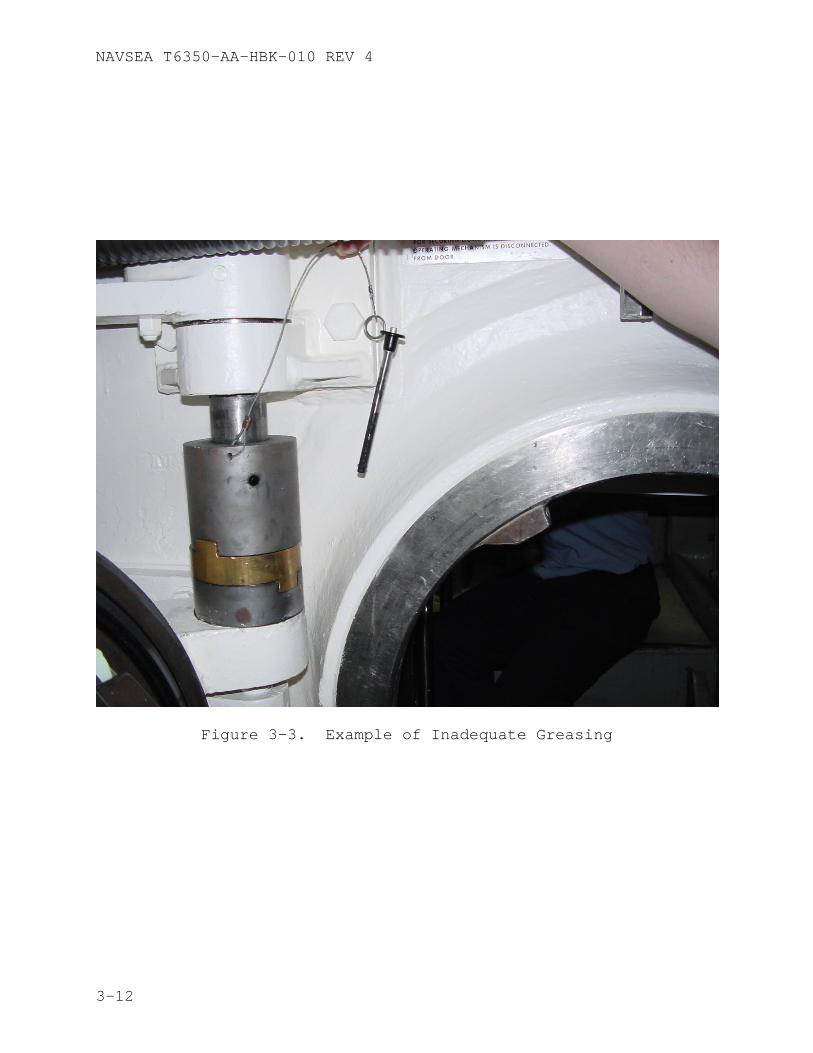
3.3.1 Inadequate Greasing Inadequate greasing (undergreasing) occurs when an insufficient quantity of grease is applied to a component. To prevent inadequate greasing, use one of the three methods to determine the quantity of grease (Observation Method, Spring Scale Method or Stroke Method), as stated in the MRC greasing procedures. If there is reason to believe the quantities provided in the MRC are insufficient, you must perform the Observation Method to determine the correct amount of grease required to properly lubricate the component. Record the amount of grease applied and compare to the quantity identified in the MRC. If there is a discrepancy submit a Technical Feedback Report. Examples of inadequately greased components are shown in Figures 3-1 through 3-4.
3-8
NAVSEA T6350-AA-HBK-010 REV 4
3.3.2 Overgreasing Overgreasing occurs when too much grease is applied to a component and is typically associated with electrical motor bearings. To prevent overgreasing, use the correct amount of grease and follow the MRC greasing procedures (refer to reference 5 for specific information on motor generator bearings).
3.3.3 Wrong Type of Grease When the wrong type of grease has been applied to a system or component, refer to the appropriate equipment technical manual and MRC for the proper corrective maintenance procedures. If corrective maintenance procedures are not contained in those documents, use procedures in Appendix D. Notify the Squadron Materiel Officer and request further guidance.
3-9
NAVSEA T6350-AA-HBK-010 REV 4
Figure 3-1. Example of Inadequate Greasing
3-10
NAVSEA T6350-AA-HBK-010 REV 4
Figure 3-2. Example of Inadequate Greasing
3-11
NAVSEA T6350-AA-HBK-010 REV 4
Figure 3-3. Example of Inadequate Greasing
3-12
NAVSEA T6350-AA-HBK-010 REV 4
Figure 3-4. Example of Inadequate Greasing
3-13
NAVSEA T6350-AA-HBK-010 REV 4
Blank
3-14
NAVSEA T6350-AA-HBK-010 REV 4
CHAPTER 4
PARTS
4.1 Supply Data
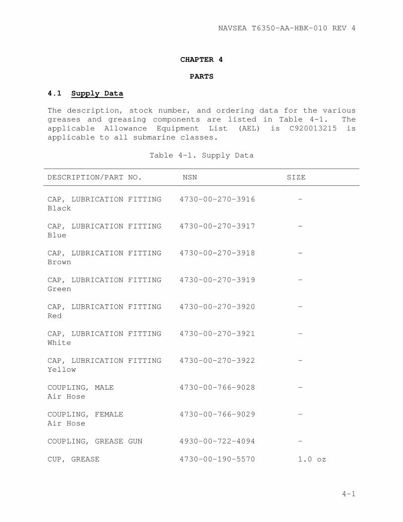
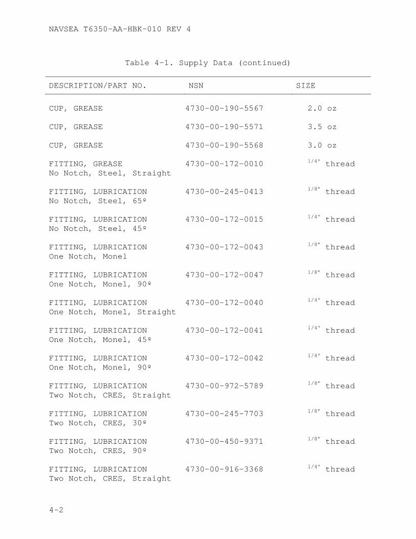
The description, stock number, and ordering data for the various greases and greasing components are listed in Table 4-1. The applicable Allowance Equipment List (AEL) is C920013215 is applicable to all submarine classes.
Table 4-1. Supply Data
DESCRIPTION/PART NO. NSN SIZE
CAP, LUBRICATION FITTING 4730-00-270-3916 - Black CAP, LUBRICATION FITTING 4730-00-270-3917 - Blue CAP, LUBRICATION FITTING 4730-00-270-3918 - Brown CAP, LUBRICATION FITTING 4730-00-270-3919 - Green CAP, LUBRICATION FITTING 4730-00-270-3920 - Red CAP, LUBRICATION FITTING 4730-00-270-3921 - White CAP, LUBRICATION FITTING 4730-00-270-3922 - Yellow COUPLING, MALE 4730-00-766-9028 - Air Hose COUPLING, FEMALE 4730-00-766-9029 - Air Hose COUPLING, GREASE GUN 4930-00-722-4094 - CUP, GREASE 4730-00-190-5570 1.0 oz
4-1
NAVSEA T6350-AA-HBK-010 REV 4
Table 4-1. Supply Data (continued)
DESCRIPTION/PART NO. NSN SIZE
CUP, GREASE 4730-00-190-5567 2.0 oz CUP, GREASE 4730-00-190-5571 3.5 oz CUP, GREASE 4730-00-190-5568 3.0 oz FITTING, GREASE 4730-00-172-0010 1/4" thread No Notch, Steel, Straight FITTING, LUBRICATION 4730-00-245-0413 1/8” thread No Notch, Steel, 65º FITTING, LUBRICATION 4730-00-172-0015 1/4" thread No Notch, Steel, 45º FITTING, LUBRICATION 4730-00-172-0043 1/8” thread One Notch, Monel FITTING, LUBRICATION 4730-00-172-0047 1/8” thread One Notch, Monel, 90º FITTING, LUBRICATION 4730-00-172-0040 1/4" thread One Notch, Monel, Straight FITTING, LUBRICATION 4730-00-172-0041 1/4" thread One Notch, Monel, 45º FITTING, LUBRICATION 4730-00-172-0042 1/4" thread One Notch, Monel, 90º FITTING, LUBRICATION 4730-00-972-5789 1/8” thread Two Notch, CRES, Straight FITTING, LUBRICATION 4730-00-245-7703 1/8” thread Two Notch, CRES, 30º FITTING, LUBRICATION 4730-00-450-9371 1/8” thread Two Notch, CRES, 90º FITTING, LUBRICATION 4730-00-916-3368 1/4" thread Two Notch, CRES, Straight
4-2
NAVSEA T6350-AA-HBK-010 REV 4
Table 4-1. Supply Data (continued)
DESCRIPTION/PART NO. NSN SIZE
FITTING, LUBRICATION 4730-00-347-6184 1/4" thread Two Notch, CRES, 45º GAGE, PRESSURE, DIAL 6685-01-330-6733 - 0-5,000 psig GAGE, PRESSURE, DIAL 6685-01-047-5112 - 0-10,000 psig LUBRICATING GUN, HAND 4930-00-253-2478 14.0 oz Type I, Lever Operated LUBRICATING GUN, HAND 4930-00-250-8038 3.0 oz Type II, Push Operated LUBRICATING GUN, HAND 4930-00-356-3924 5.0 oz Type II, Push Operated LUBRICATING GUN, HAND 4930-00-965-0288 16.0 oz Type IV, Pistol Grip Operated HOSE ASSEMBLY, GREASE 4720-00-066-4759 50 ft PUMP, LUBRICANT TRANSFER 4930-01-223-3730 - Pneumatic SCALE, WEIGHING 6670-00-240-5831 - 0-100 Pounds SCALE, WEIGHING 6670-01-010-5906 - 0-60 Pounds SWIVEL, LUBRICATION 4930-00-759-0639 - NIPPLE, PIPE 4730-00-196-1487 1/4" thread 3” Length NIPPLE, PIPE 4730-00-196-1541 1/4" thread 6” Length
4-3
NAVSEA T6350-AA-HBK-010 REV 4
Table 4-1. Supply Data (continued)
DESCRIPTION/PART NO. NSN SIZE
PIPE PLUG 4730-00-279-0985 1/4" thread TEE, PIPE 4730-00-263-5264 1/4" thread 3000PSI VALVE, REGULATING, FLOW 4820-01-250-8597 1/4" thread 250 psi Inlet - Max 160 psi Outlet – Max VALVE, SAFETY RELIEF 4820-00-454-7586 1/4" thread 100 psi Opening Pressure PARTS KIT, AIR MOTOR 4320-01-315-7662 - PARTS KIT, LUBRICANT PUMP 4930-01-305-9865 -
The Pneumatic grease pumps are supplied with service instructions which contain assembly procedures, maintenance procedures, and a repair parts list. This instruction booklet should be utilized when ordering repair parts and conducting maintenance.
4-4
NAVSEA T6350-AA-HBK-010 REV 4
CHAPTER 5
NOISE PROBLEMS
5.1 Troubleshooting Noise Problems
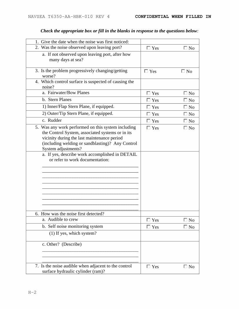
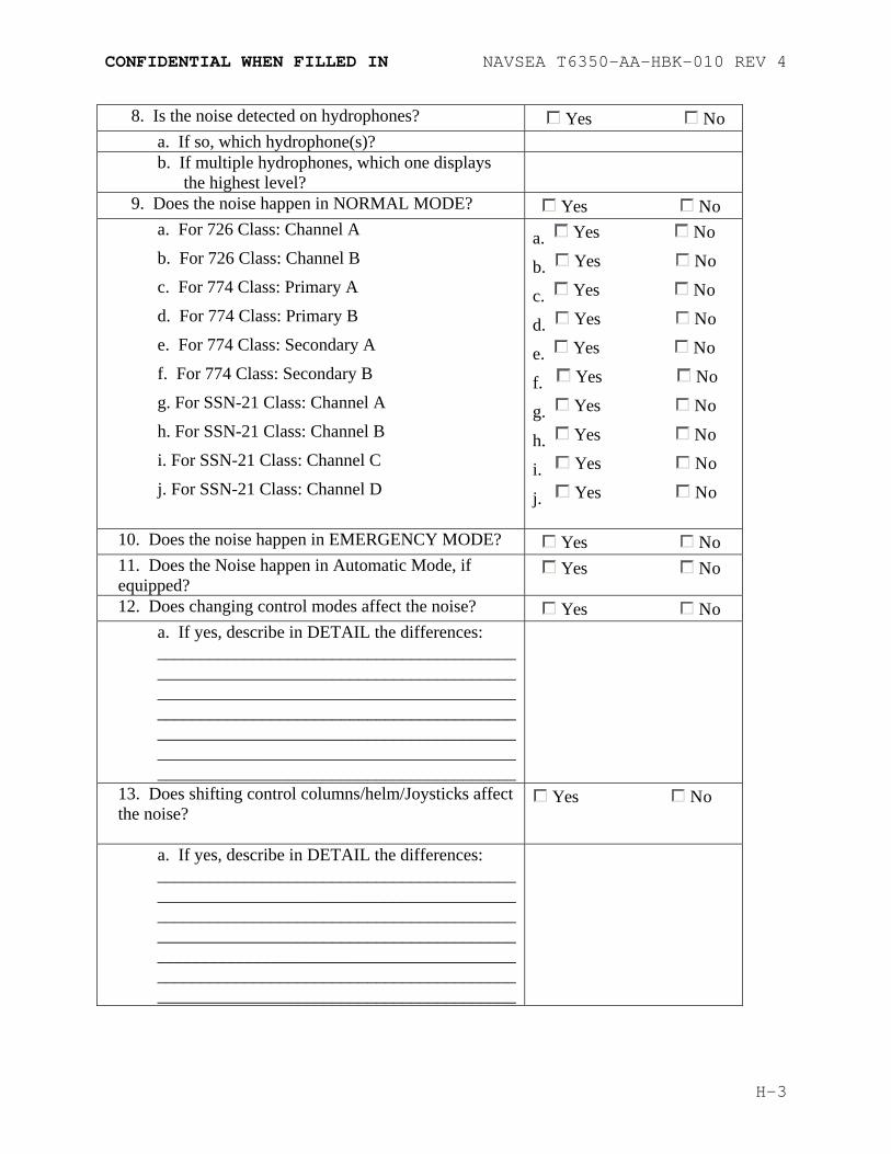
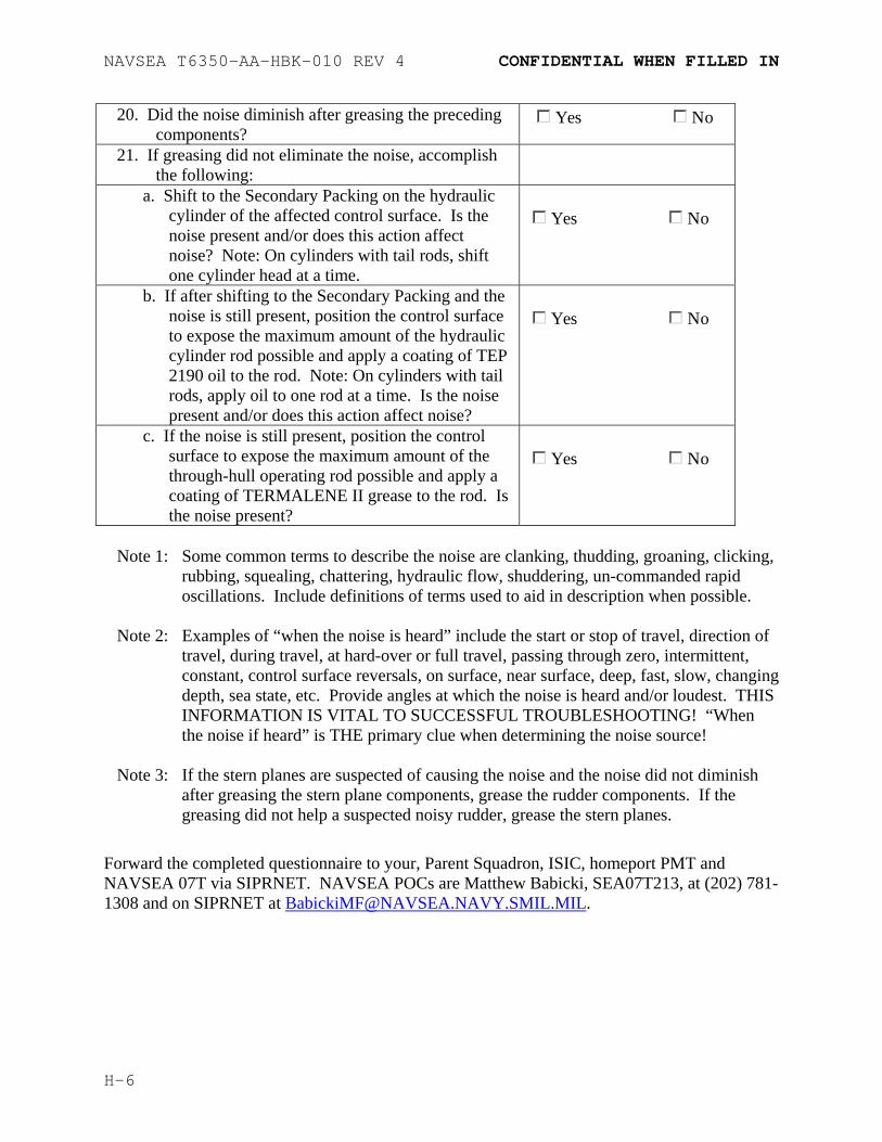
5.1.1 Noise Questionnaire The noise questionnaire in Appendix H is representative of the questionnaire used to troubleshoot suspected noise problems in steering and diving systems. The logic behind the questionnaire can be applied to any lubricated system to aid in determining a noise source. Simple deductive reasoning is used as one progresses through the questionnaire from smallest to largest component, and from most likely to least likely noise source. Completion of this questionnaire can be a great help to ship’s force, saving many unnecessary hours of greasing a component that does not require greasing, as well as assisting the IMAs by specifically identifying a noise source.
5-1
NAVSEA T6350-AA-HBK-010 REV 4
Blank
5-2
NAVSEA T6350-AA-HBK-010 REV 4
CHAPTER 6
INSPECTION
6.1 Submarine Lubrication Systems and Equipment Inspection
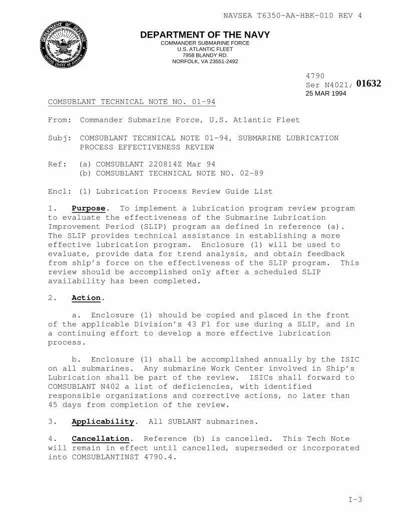
6.1.1 Submarine Lubrication Process Effectiveness Review The Submarine Lubrication Improvement Period (SLIP) was implemented by COMSUBPAC in March 1994 via COMSUBLANT TECHNICAL NOTE NO. 01-94 to provide technical assistance in establishing a more effective lubrication program. The SLIP program is written to have the ISIC accomplish the review, but can and should be used by each submarine that does not utilize the SLIP program. Appendix I contains COMSUBLANT TECHNICAL NOTE NO. 01-94, which can be adapted for each submarine to have senior divisional personnel perform the review. This review will ensure that the lubrication equipment is in accordance with the requirements of this manual, MRCs and EGLs are current, and that the personnel performing the greasing fully understands the greasing requirements.
6-1
NAVSEA T6350-AA-HBK-010 REV 4
Blank
6-2
NAVSEA T6350-AA-HBK-010 REV 4
APPENDIX A
REFERENCES
The following references were used to prepare this handbook. Some references are referred to specifically in the text while others were used for information without direct reference.
2. NAVSEA Instruction 9210.41B dated 10 Oct 1990, Requirements for Use of Standard Lubricants and Penetrating Fluid for all Naval Nuclear Propulsion Plants.
6. MIL-HDBK-267, Guide for Selection of Lubricants and Hydraulic Fluids for use in Shipboard Equipment.
7. MIL-HDBK-200, Quality Surveillance Handbook for Fuels, Lubricants and Related Products.
8. MIL-G-3859, Grease Guns, Hand-Operated, Lever, Push and Screw Type.
9. MIL-F-3541B, Fittings, Lubrication.
10. Standard Maintenance Procedures OPs 3751, 4429 and 4489.
11. Preventive Maintenance Management Plans.
A-1
NAVSEA T6350-AA-HBK-010 REV 4
Blank
A-2
NAVSEA T6350-AA-HBK-010 REV 4
APPENDIX B
LIST OF SYSTEMS AND COGNIZANT NAVSEA ENGINEERS
The systems covered by this manual are presented below. Additionally, the cognizant NAVSEA Life Cycle Manager, SEA 07T engineer and their phone numbers are listed.
Steering and Diving SEA 05Z52 SEA 07T315 (Hydraulic Linkage) 202-781-3601 202-781-1308 Steering and Diving SEA 05Z52 SEA 07T315 (Bearings and 202-781-3601 202-781-1308 Control Surfaces) Trash Disposal Unit SEA 07T125 202-781-3226 Torpedo Tubes SEA 05Z7 SEA 07T11 (Auxiliary) 202-781-3717 202-781-1126 Trim and Drain Pump SEA 07T22 and Motor Bearings 202-781-5581 Ventilation SEA 05Z9H2 SEA 07T334 202-781-3649 202-781-1132 Vertical Launch SEA 05Z7 SEA 07T116 System 202-781-3717 202-781-2533 All Other Topside SEA 07T126 Fittings 202-781-3023 The Naval Surface Warfare Center Carderock (NSWC-CD) Philadelphia PA, Code 62 is the NAVSEA In-Service Engineering Agent (ISEA) for greases and lubricants. Technical questions regarding grease chemistry, material testing procedures, lubricant qualification, environmental handling and grease disposal can be addressed directly to the ISEA Engineering Staff for technical assistance. Please contact the following engineering personnel at NSWC-CD: Ms. Vicky Larimore (215) 897-8508 Ms. Erin Murcko (215) 897-7577 Ms. Terry Steck (215) 897-7478
B-2
NAVSEA T6350-AA-HBK-010 REV 4
APPENDIX C
LUBRICATION DISTRIBUTION VALVE DRAWINGS
Class Drawing Number
SSN 688 516-4498674
SSGN/SSBN 726 845-4687570
SSN 21 546-6408671
SSN 774 546-6985455
C-1
NAVSEA T6350-AA-HBK-010 REV 4
Blank
C-2
NAVSEA T6350-AA-HBK-010 REV 4
APPENDIX D
CORRECTIVE PROCEDURES PROCEDURE PAGE 1. Alternate Methods of Clearing a Grease D-2 Plugged Component. 2. Removing Incorrect Grease From Grease Line. D-3 3. Freeing Hatch Hinges D-4
D-1
NAVSEA T6350-AA-HBK-010 REV 4
Procedure 1
Alternate Method of Clearing a Grease Plugged Component
A. HAND PUMP PROCEDURE
1. Obtain a hydraulic hand pump.
2. Fill hand pump with automatic transmission fluid (ATF) or any suitable solvent which meets forces afloat safety requirements.
3. Connect hand pump to the plugged component’s grease line using a temporary line fitted with a 0-5000 psig test gauge.
4. Open the hull stop, position distribution valve to line suspected of being clogged (if applicable). Using the hand pump, pressurize the ATF and pump to the affected line. Ensure the grease line and component are not over pressurized (see CAUTION for plugged grease lines, paragraph 3.2.2.1).
5. As the ATF penetrates the clogged grease line, the pressure will begin to decrease. Operate the hand pump to maintain pressure. When the line is cleared, pressure will decrease to near zero. When this occurs, use the hand pump to deliver approximately one quart of ATF to fully purge the old grease.
6. Remove temporary equipment and restore the system.
7. Using the observation method, Paragraph 2.2.1.7.1 grease component with fresh grease. Grease until the grease line and component is purged of all solvent.
B. PNEUMATIC GREASE GUN PROCEDURE
1. Obtain a pneumatic grease pump.
2. Mix a 50/50 solution of grease normally used in the component being flushed and automatic transmission fluid (ATF) or any suitable solvent which meets forces afloat safety requirements in a 35 pound pneumatic grease pump adaptable container.
3. Assemble pneumatic grease pump and connect to the plugged component’s grease line.
D-2
NAVSEA T6350-AA-HBK-010 REV 4
4. Open the hull stop and position distribution valve to line suspected of being clogged (if applicable). Using the pneumatic grease pump, pressurize the affected line. Ensure the grease line and component are not over-pressurized (see CAUTION for plugged grease lines, paragraph 3.2.2.1).
5. As the ATF penetrates the clogged grease line, the pressure will begin to decrease. Operate the pneumatic grease pump to maintain pressure. When the line is cleared, pressure will decrease significantly. When this occurs, use the pneumatic grease pump to deliver approximately one quart of ATF to fully purge the old grease.
6. Remove temporary equipment and restore the system.
7. Using the observation method, Paragraph 2.2.1.7.1 grease component with fresh grease, using the “Total Grease Cavity Amount” identified in the applicable MRC. Grease until the grease line and component is purged of all solvent.
Procedure 2
Removing Incorrect Grease From Grease Line
1. Determine the diameter and approximate length of the grease line from ship's drawing.
2. Increase the approximate length by ten percent (10%) to account for bends, detours, etc.
3. Determine amount of grease in piping using the following formula: a. 1/4 inch grease line: line length in feet (from Step 2)
X (0.31) = ounces of grease. Divide the result by 16 to convert to pounds.
b. 3/8 inch grease line: line length in feet (from Step 2)
X (0.69) = ounces of grease. Divide the result by 16 to convert to pounds.
4. Determine, from the ship’s drawings, if the bearing involved has a grease cavity. If so, determine the amount of grease in the cavity using the following formula: a. CAVITY VOLUME (cubic inches) X (0.40) = OUNCES OF
GREASE.
D-3
NAVSEA T6350-AA-HBK-010 REV 4
b. Divide the result by 16 to convert to pounds.
5. Determine the size (diameter in inches) of the bearing involved. The amount of grease needed for the bearing is: a. BEARING SIZE (inches) X 64 = OUNCES OF GREASE. b. Divide the result by 16 to convert to pounds.
6. Add the amounts determined in steps 3, 4, and 5 above. This is the MINIMUM amount of grease (in pounds) needed to purge the grease line, cavity and bearing of the incorrect grease and properly lubricate the bearing.
7. Using the observation method, Paragraph 2.2.1.7.1 grease component with fresh grease using the calculated amounts above. Grease until the grease line and component is purged of all solvent.
8. Repeat this procedure for each grease line which was incorrectly greased.
Procedure 3
Freeing Hatch Hinges
1. Obtain a manual grease pump filled with CID A-A-50433 approved grease. If a manual grease pump filled with CID A-A-50433 approved grease is not available, clean a Type I or Type IV grease pump in accordance with paragraph 2.2.2.6.
2. Fill the grease pump with CID A-A-50433 approved grease, leaving a one inch space at the top.
3. Fill the one inch space with penetrating oil and place the head back on the grease pump.
4. Grease all of the hatch hinge fittings using the CID A-A-50433 approved grease/penetrating oil mixture.
5. Cycle the hatch open and shut until smooth operation is obtained.
6. Clean the grease pump in accordance with paragraph 2.2.2.6.
7. Using clean CID A-A-50433 approved grease, flush the hatch hinge fittings until the penetrating oil mixture has been purged from the hinges.
CID Commercial Item Description (replaces Military Specifications where authorized)
CRES Corrosion Resistant Steel
EGL Equipment Guide List
MIP Maintenance Index Page
MONEL Nickel-Copper Alloy
MRC Maintenance Requirement Card
NSTM Naval Ships Technical Manual
PMS Planned Maintenance System
PSIG Pounds per square inch gauge
PMMP Preventive Maintenance Management Plan
SMP Standard Maintenance Procedure
TDC Technical Data Center
F-1
NAVSEA T6350-AA-HBK-010 REV 4
Blank
F-2
NAVSEA T6350-AA-HBK-010 REV 4
APPENDIX G
TESTING REQUIREMENTS FOR
GREASE, SEAWATER WASH RESISTANT
G.1. Grease Testing To insure that only grease of the highest quality is delivered to the Navy, stringent testing requirements must be met. This testing shall be accomplished for any grease proposed for use under Commercial Item Description (CID) A-A-50433 for seawater wash resistant grease. As a minimum this testing will require compliance with the Nuclear Submarine Atmosphere Control Manual, NAVSEA S9520-AB-ATM-010/(U), the testing requirements of the CID, and meet or exceed pumpability standards established by the Naval Air Development Center (NADC) Warminster, Pa. in NADC report serial 4123/6061 ser 007131 dated 17 Aug 1989.
G.1.1. Testing Requirements for Cid A-A-50433, Grease, Seawater Wash Resistant
G.1.1.1. Testing Requirements Grease supplied for this usage category must comply with the requirements of the Nuclear Powered Submarine Atmosphere Control Manual, NAVSEA S9520-AB-ATM-010/(U), the Submarine Greasing Handbook, NAVSEA T6350-AA-HBK-010, NADC report serial 4123/6061 ser 007131 dated 17 Aug 1989, and meet the following typical specifications (ASTM test procedures are listed where applicable): TEST ACCEPTABLE CHARACTERISTICS TEST PROCEDURE Worked penetration 240-295 ASTM D-217 @ 77º F, 60 strokes Penetration after 100,000 295 ASTM D-217 strokes maximum Maximum apparent viscosity 300 poises @ 200 ASTM D-1092 Sec-1 and 32º F Drop point (ºF) minimum 500+ ASTM D-566 Gelling agent Aluminum complex N/A % alkali, maximum 0 ASTM D-128 % water, maximum 0 ASTM D-1744 % molybdenum disulfide, maximum 0 N/A Free fatty acid, % maximum 0.01 ASTM D-128
G-1
NAVSEA T6350-AA-HBK-010 REV 4
Oxygen stability, 50 psi Maximum drop ASTM D-942 at 210º F for 100 hrs. 4 psi TEST ACCEPTABLE CHARACTERISTICS TEST PROCEDURE Water resistance (maximum < 65% ASTM D-4049 spray off) Corrosion on copper, maximum 1B ASTM D-4048 Operating range +15 to 350º F N/A Elastomer compatibility ASTM D-4289 with NBR-L and FKM Maximum volumetric change < +10% and > 0% Maximum hardness change < + 5 Durometer Points Steel on steel wear < 1.25 mm wear scar ASTM D-3704 after 90 minutes at 60 cycles per minute at 30 lb load with 90 deg angle of oscillation, H-30 test block and S-10 test ring. Pumpability performance Satisfactory NADC test
G.1.1.3. Acceptability The grease shall have each acceptable characteristic listed above when tested in accordance with the respective test method.
G.1.1.4. Certification The contractor shall certify, and maintain substantiating evidence, that the product offered meets the salient characteristics of this CID, and the product conforms to the producer’s own drawings, specifications, standards, and quality assurance practices. The Government reserves the right to require proof of such conformance prior to first delivery and thereafter as may be otherwise provided for under the provisions of the contract.
G.1.1.5. Preservation, Packaging, Packing, Labeling And Marking Preservation, packaging, labeling, and marking shall be as specified in the contract order. The container size shall be 35 pound (5 gallon) cylindrical (non-tapered) cans suitable for use
G-2
NAVSEA T6350-AA-HBK-010 REV 4
with pneumatic grease pumps with follower plates such as Alemite 711H or equivalent.
G.1.2. Testing Requirements for Other Greases Testing requirements for other greases used aboard submarines shall be as defined by appropriate Military Specifications or CID. Additional testing or certification will be accomplished as needs of the fleet are expressed.
G.2. General
G.2.1. ASTM Standards. ASTM Standards are available from: ASTM INTERNATIONAL 100 Barr Harbor Drive P.O. Box C700 West Conshohocken, PA 19428-2959 WEB SITE: HTTP://WWW.ASTM.ORG
G.2.2. Procurement It shall be incumbent on the procuring agency to insure that any grease supplied for this CID complies with the requirements of NAVSEA S9520-AB-ATM-010/(U) and NAVSEA T6350-AA-HBK-010. Points of contact at Naval Sea Systems Command are NAVSEA 05M3 (202) 781-3840 and NAVSEA 07T313 (202) 781-1350.
G-3
NAVSEA T6350-AA-HBK-010 REV 4
Blank
G-4
CONFIDENTIAL WHEN FILLED IN NAVSEA T6350-AA-HBK-010 REV 4
APPENDIX H CONTROL SURFACE NOISE TROUBLESHOOTING PROCEDURE
AND QUESTIONNAIRE 1. The objective of this questionnaire is to provide a common fact finding methodology and
documentation tool to facilitate: a) Troubleshoot and potentially eliminate the noise while underway. b) Assist in troubleshooting upon return to port if not eliminated while underway. c) Identify corrective actions. 2. Accurate and detailed descriptions of the noise characteristics are vital in the identification of
the noise source. Such as: What (type of noise, dynamics of noise), When (ship speed/deflection angles/change in travel direction dynamics/modes & intermittent/repeatability), Where (inboard/outboard, port/starboard, ram/operating gear), and Why (if applicable)
3. Previous experience has found that the above information is useful in focusing attention to or
eliminating specific portions of the system(s). Remember the better the information regarding the noise, the better the mitigation/correction results.
The principle causes of adverse Steering and Diving system noises are typically inadequate grease, recently completed repairs/adjustments, and/or the wearing out of the outboard components and the components of the Control System. The Control System encompasses all inboard components, including the control columns, electrical and electronic components, hydraulic control valves, feedback linkages, etc. Problems in the Control System normally manifest themselves initially as a noise, eventually causing excessive wear, and damage to the outboard components. Sometimes the outboard bearings appear to be the noise source, but are only reacting to the commands of a compromised Control System.
NAVSEA T6350-AA-HBK-010 REV 4 CONFIDENTIAL WHEN FILLED IN
Check the appropriate box or fill in the blanks in response to the questions below:
1. Give the date when the noise was first noticed: 2. Was the noise observed upon leaving port? Yes No
a. If not observed upon leaving port, after how many days at sea?
3. Is the problem progressively changing/getting worse? Yes No
4. Which control surface is suspected of causing the noise?
a. Fairwater/Bow Planes Yes Nob. Stern Planes Yes No1) Inner/Flap Stern Plane, if equipped. Yes No2) Outer/Tip Stern Plane, if equipped. Yes Noc. Rudder Yes No
5. Was any work performed on this system including the Control System, associated systems or in its vicinity during the last maintenance period (including welding or sandblasting)? Any Control System adjustments?
Yes No
a. If yes, describe work accomplished in DETAIL or refer to work documentation:
6. How was the noise first detected? a. Audible to crew Yes Nob. Self noise monitoring system Yes No
(1) If yes, which system?
c. Other? (Describe) __________________________________________________________________________________ _________________________________________
7. Is the noise audible when adjacent to the control surface hydraulic cylinder (ram)? Yes No
H-2
CONFIDENTIAL WHEN FILLED IN NAVSEA T6350-AA-HBK-010 REV 4
8. Is the noise detected on hydrophones? Yes Noa. If so, which hydrophone(s)? b. If multiple hydrophones, which one displays
the highest level?
9. Does the noise happen in NORMAL MODE? Yes No a. For 726 Class: Channel A
b. For 726 Class: Channel B
c. For 774 Class: Primary A
d. For 774 Class: Primary B
e. For 774 Class: Secondary A
f. For 774 Class: Secondary B
g. For SSN-21 Class: Channel A
h. For SSN-21 Class: Channel B
i. For SSN-21 Class: Channel C
j. For SSN-21 Class: Channel D
a. Yes No
b. Yes No
c. Yes No
d. Yes No
e. Yes No
f. Yes No
g. Yes No
h. Yes No
i. Yes No
j. Yes No
10. Does the noise happen in EMERGENCY MODE? Yes No 11. Does the Noise happen in Automatic Mode, if equipped? Yes No
12. Does changing control modes affect the noise? Yes No a. If yes, describe in DETAIL the differences: _______________________________________________________________________________________________________________________________________________________________________________________________________________________________________________________________________________________________
13. Does shifting control columns/helm/Joysticks affect the noise?
Yes No
a. If yes, describe in DETAIL the differences: _______________________________________________________________________________________________________________________________________________________________________________________________________________________________________________________________________________________________
H-3
NAVSEA T6350-AA-HBK-010 REV 4 CONFIDENTIAL WHEN FILLED IN
14. Does either rapid or slow control
column/helm/Joystick movement affect the noise? Yes No
a. If yes, describe in DETAIL the differences: ______________________________________________________________________________________________________________________________________________________________________________________________________________________________________________________________________________________________________ __________________________________________
15. Describe the type of noise heard in DETAIL (See Note 1 for examples): ___________________________________________________________________________________________________________________________________________________________________________________________________________________________________________________________________________________________________________________________________________________________________________________________________________________________________________________________________
16. Describe in DETAIL when the noise is heard (See Note 2 for examples): __________________________________________________________________________________________________________________________________________________________________________________________________________________________________________________________________________________________________________________________________________________________________________________________________________________________
17. Is there any unusual hesitancy, lost motion or when observing the local mechanical indication and feedback mechanisms during operation of the control surface?
Yes No
H-4
CONFIDENTIAL WHEN FILLED IN NAVSEA T6350-AA-HBK-010 REV 4
a. If yes, describe in DETAIL the hesitancy or
motion and at what angle and direction of travel: _______________________________________________________________________________________________________________________________________________________________________________________________________________________________________________________________________________________________
18. Are any of the following components very warm to the touch after operating the control surface suspected of causing the noise?
a. Hydraulic tail rod (if equipped or design includes)? Yes No
b. Hydraulic piston rod? Yes Noc. Through hull connecting rod? Yes No
19. On the control surface suspected of causing the noise, perform the appropriate quarterly greasing MRC doubling the amount of grease specified in the MRC. Grease all components specified in the MRC.
o GREASE ONE COMPONENT AT A TIME
AND OBSERVE FOR ANY CHANGE IN NOISE LEVEL OR FREQUENCY.
o IF DURING OR AFTER GREASING A
COMPONENT, THE NOISE STOPS OR REDUCES, STOP GREASING, THIS MIGHT BE THE OFFENDING COMPONENT.
NOTE: IF POSSIBLE, OPERATE THE SYSTEM IN THE MANNER THAT MAKES THE NOISE OCCUR WHILE GREASING. NOTE: IF THE NOISE RETURNS AFTER CONTINUED CYCLING, RE-GREASE THE OFFENDING COMPONENT. IF THE NOISE STOPS OR REDUCES ANNOTATE WHICH COMPONENT IS AFFECTED AND CONTINUE GREASING THE REMAINDER OF COMPONENTS. MULTIPLE NOISE OFFENDERS ARE POSSIBLE. SEE NOTE 3.
H-5
NAVSEA T6350-AA-HBK-010 REV 4 CONFIDENTIAL WHEN FILLED IN
20. Did the noise diminish after greasing the preceding components? Yes No
21. If greasing did not eliminate the noise, accomplish the following:
a. Shift to the Secondary Packing on the hydraulic cylinder of the affected control surface. Is the noise present and/or does this action affect noise? Note: On cylinders with tail rods, shift one cylinder head at a time.
Yes No
b. If after shifting to the Secondary Packing and the noise is still present, position the control surface to expose the maximum amount of the hydraulic cylinder rod possible and apply a coating of TEP 2190 oil to the rod. Note: On cylinders with tail rods, apply oil to one rod at a time. Is the noise present and/or does this action affect noise?
Yes No
c. If the noise is still present, position the control surface to expose the maximum amount of the through-hull operating rod possible and apply a coating of TERMALENE II grease to the rod. Is the noise present?
Yes No
Note 1: Some common terms to describe the noise are clanking, thudding, groaning, clicking,
rubbing, squealing, chattering, hydraulic flow, shuddering, un-commanded rapid oscillations. Include definitions of terms used to aid in description when possible.
Note 2: Examples of “when the noise is heard” include the start or stop of travel, direction of
travel, during travel, at hard-over or full travel, passing through zero, intermittent, constant, control surface reversals, on surface, near surface, deep, fast, slow, changing depth, sea state, etc. Provide angles at which the noise is heard and/or loudest. THIS INFORMATION IS VITAL TO SUCCESSFUL TROUBLESHOOTING! “When the noise if heard” is THE primary clue when determining the noise source!
Note 3: If the stern planes are suspected of causing the noise and the noise did not diminish
after greasing the stern plane components, grease the rudder components. If the greasing did not help a suspected noisy rudder, grease the stern planes.
Forward the completed questionnaire to your, Parent Squadron, ISIC, homeport PMT and NAVSEA 07T via SIPRNET. NAVSEA POCs are Matthew Babicki, SEA07T213, at (202) 781-1308 and on SIPRNET at [email protected].
Ref: (a) COMSUBLANT 220814Z Mar 94 (b) COMSUBLANT TECHNICAL NOTE NO. 02-89 Encl: (1) Lubrication Process Review Guide List
1. Purpose. To implement a lubrication program review programto evaluate the effectiveness of the Submarine Lubrication Improvement Period (SLIP) program as defined in reference (a). The SLIP provides technical assistance in establishing a more effective lubrication program. Enclosure (1) will be used to evaluate, provide data for trend analysis, and obtain feedback from ship’s force on the effectiveness of the SLIP program. Thireview should be accomplished only after a scheduled SLIP availability has been completed.
2. Action.
a. Enclosure (1) should be copied and placed in the front of the applicable Division’s 43 P1 for use during a SLIP, and ina continuing effort to develop a more effective lubrication process.
b. Enclosure (1) shall be accomplished annually by the ISIon all submarines. Any submarine Work Center involved in Ship’sLubrication shall be part of the review. ISICs shall forward toCOMSUBLANT N402 a list of deficiencies, with identified responsible organizations and corrective actions, no later than 45 days from completion of the review.
3. Applicability. All SUBLANT submarines.
4. Cancellation. Reference (b) is cancelled. This Tech Note will remain in effect until cancelled, superseded or incorporateinto COMSUBLANTINST 4790.4.
01632
-3
s
C
d
NAVSEA T6350-AA-HBK-010 REV 4
Subj: COMSUBLANT TECHNICAL NOTE 01-94, SUBMARINE LUBRICATION PROCESS EFFECTIVENESS REVIEW
J. D. CONNERS By direction Distribution: SNDL Parts 1 and 2 24G2 SUBMARINE FORCE COMMANDER PAC 26VV1 COMSUBLANT SHIPYARD REPS 28K1 SUBMARINE GROUP AND SQUADRON LANT 29N1 SUBMARINE LANT (SSN) 29Q1 FLEET BALLISTIC MISSILE SUBMARINE LANT (SSBN) 29S RESEARCH SUBMARINE (NUCLEAR) (NR) 32DD1 SUBMARINE TENDER LANT (AS) FA13 SUBMARINE SUPPORT FACILITY LANT FF8 INSPECTION AND SURVEY BOARD (PRESINSURV) FKA1G SEA SYSTEMS COMMAND (PMS 390, PMS 393, PMS 396) FKA11 TRIDENT REFIT FACILITY DIRSSP FKP7 NAVAL SHIPYARD (LESS LONG BEACH & PHILADELPHIA) FKP8 SUPERVISOR OF SHIPBUILDING (GROTON & NEWPORT NEWS ONLY) FKP23 NAVNUCPWRSCOL FT54 SCOL SUBMARINE FT95 SUBTRAFAC (LESS SAN DIEGO) FT98 NUCLEAR FIELD “A” SCOL FT27 NAVNUCPWRTRAU
I-4
NAVSEA T6350-AA-HBK-010 REV 4
LUBRICATION PROCESS REVIEW GUIDE LIST
ADMIN PHASE
1. Are the ship’s lubrication charts on board and being used by the maintenance personnel?
2. Is the SUBMARINE GREASING HANDBOOK (NAVSEA T6350-AA-HBK-010) on board and available for use by all divisional maintenance personnel involved with ships lubrication?
3. Is NAVSHIPS Technical Manual Chapter 262 on board and available for reference?
4. Does the applicable division document quarterly training? Minimum requirements to include: EGL and lube chart set up, the proper lubrication method for various bearing applications, precautions involved in lubricating components external to the hull, procedures for identifying and clearing a plugged grease line, how to properly lubricate reach rod knuckles with Flush Mounts, and max allowable lubrication pressures.
5. Do the ship’s EGLs for lubrication list all components identified on the lubrication charts? Do the EGLs list the amount of lubricant, method of application, number of lubrication points and MIL-SPEC of the lubricant to be used?
6. Do the ship’s lubrication charts reflect equipment as actually installed? For all valves not on the DWG has the ship entered them on an A-111 EGL?
7. Do the ships EGLs cover reach rod lubrication, rising stem valve lubrication, sliding deck clip lubrication (if applicable), and valve gear box lubrication?
8. Are electrical motors that require lubrication listed on the divisional EGLs? Do the EGLs list quantity and type of grease.
SYSTEM INSPECTION
1. Observe the operation of the ship’s pneumatic grease pump while conducting lubrication PMS. Observe how the grease is weighed and how the grease pump is suspended. Does the maintenance person understand what the maximum allowable grease pressure is for the component being lubricated? Is the spring scale used to weigh the grease calibrated and on the ships recall list?
Encl (1) I-5
NAVSEA T6350-AA-HBK-010 REV 4
2. Does the maintenance person understand how to recognize a plugged grease line and the procedures available to clear that line?
3. Inspect the pneumatic grease pump to ensure it is in compliance with the MRC card. Check the installed gages for current calibration. If the ship has only one pneumatic grease pump on board recommend the ship submit a Fleet COSAL Feedback Report to increase the allowance to two to provide a backup.
4. Inspect the Trim and Drain pump upper bearing for the presence of the correct grease. Is the grease line to the lower bearing crimped, or disconnected? Does the ship have the correct PMS coverage necessary to lubricate the Trim and Drain pump couplings?
5. Inspect the Ventilation Exhaust and Induction Valves for evidence of lubrication. Ensure all Lubrication fittings are accessible and unobstructed. Verify the ships ability to properly lubricate these valves IAW MRC, (to include Head Valve power cylinder and Induction Mast V ring packing).
6. Inspect all gear driven ball valve operators for evidence of lubrication. Plugs should be removed from gear housings and a lubrication fitting installed.
7. Visually inspect all stow joints and universal joints. Ensure the bullet type fittings are available (if applicable), and are being used. For universals without flush mounts are they being hand lubricated with 2190. Inspect for joints that are painted over or corroded. Operate the reach rod to inspect for any binding or lost motion causing the valve not to operate freely. (IE: Bilge area Drain Suction Valves)
8. Inspect all hand held grease guns to see if they are labeled as to what MIL-SPEC grease is loaded in them.
9. Inspect all hand held oilers to see if they are labeled as to what MIL-SPEC oil is in them.
10. Review all electrical motors for the following: a. Are all grease plugs installed? b. Are grease plugs painted? If so, is the paint new or are there several coats indicating that the bearing has not been lubricated? c. Are the grease tubes of adequate length and aligned properly to allow lubrication?
I-6
NAVSEA T6350-AA-HBK-010 REV 4
d. Are grease cups available for each application? Are the grease cups the right size for each motor?
11. Review all systems which require lubrication. The inspection consists of the following: a. Inspect all lubrication fittings for the following:
(1) Are they made of the correct material? (All fittings used in sea water systems, or exposed to sea water leakage or spray are to be made of non-ferrous material.)
(2) Verify the fitting is correct for the application. Example: Ball check or through type zerk.
(3) Is the fitting aligned such that it can be lubricated?
(4) Is the fitting damaged, corroded or painted such that it will not accept grease?
b. Are grease boots installed where required? (Escape trunks and sail area.) c. Has excess grease been removed? Is there a buildup of grease below the component being lubricated?
12. Inspect the grease locker for the following: a. Is there adequate room for stowage of grease? b. Is the grease/lubricant labeled as an atmosphere
contaminant where applicable? c. Are all required lubricants specified by MRC
requirements maintained on board?
13. Inspect all hatches and watertight doors for the correct lubrication and condition of all lubrication fittings. Are the hatches properly protected (ie. pillow cases) installed to prevent debris from contaminating the grease.
14. Inspect fairwater planes and indicator linkage for lubrication.
15. Inspect the clam shell hinges in the sail and the whistle door operating linkage for lubrication.
I-7
NAVSEA T6350-AA-HBK-010 REV 4
16. Inspect all topside lubrication, in particular the cleats and head valve. All topside/sail area lubrication fittings are to be of the non-ferrous type.
I-8
NAVSEA T6350-AA-HBK-010 REV 4
LUBRICATION PROCESS REVIEW GUIDE LIST In accordance with COMSUBLANT Tech Note 1-94, a lubrication process review was conducted on (Ship Name) on (date) . The results of the inspection are noted below, specific divisional deficiencies will be annotated on the last page of this guide list.
ATTRIBUTE FINDINGS 1. Are the ship’s lubrication charts on board and being used by the maintenance personnel?
A Div Yes/No/ N/A TM Div Yes/No/ N/A M Div Yes/No/ N/A E Div Yes/No/ N/A
2. Is the SUBMARINE CREASING HANDBOOK (NAVSEA T6350-AA-HBK-010) on board and available for use by all divisional maintenance personnel involved with ships lubrication?
A Div Yes/No/ N/A TM Div Yes/No/ N/A M Div Yes/No/ N/A E Div Yes/No/ N/A
3. Is NAVSHIPS Technical Manual Chapter 262 on board and available for reference?
A Div Yes/No/ N/A TM Div Yes/No/ N/A M Div Yes/No/ N/A E Div Yes/No/ N/A
4. Does the applicable division document quarterly training? Minimum requirements to include: EGL and lube chart set up, the proper lubrication method for various bearing applications, precautions involved in lubricating components external to the hull, procedures for identifying and clearing a plugged grease line, how to properly lubricate reach rod knuckles with Flush Mounts, and max allowable lubrication pressures.
A Div Yes/No/ N/A TM Div Yes/No/ N/A M Div Yes/No/ N/A E Div Yes/No/ N/A
5. Do the ship’s EGLs for lubrication list all components identified on the lubrication charts? Do the EGLs list the amount of lubricant, method of application, number of lubrication points and MIL-SPEC of the lubricant to be used?
A Div Yes/No/ N/A TM Div Yes/No/ N/A M Div Yes/No/ N/A E Div Yes/No/ N/A
6. Do the ship’s lubrication charts reflect equipment as actually installed? For all valves not on the DWG has the ship entered them on an A-111 EGL?
A Div Yes/No/ N/A TM Div Yes/No/ N/A M Div Yes/No/ N/A E Div Yes/No/ N/A
7. Do the ships EGLs cover reach rod lubrication, rising stem valve lubrication, sliding deck clip lubrication (if applicable), and valve gear box lubrication?
A Div Yes/No/ N/A TM Div Yes/No/ N/A M Div Yes/No/ N/A E Div Yes/No/ N/A
8. Are electrical motors that require lubrication listed on the divisional EGLs? Do the EGLs list quantity and type of grease.
A Div Yes/No/ N/A TM Div Yes/No/ N/A M Div Yes/No/ N/A E Div Yes/No/ N/A
Encl (1) I-9
NAVSEA T6350-AA-HBK-010 REV 4
SYSTEMS REVIEWATTRIBUTE FINDINGS
1. Observe the operation of the ship’s pneumatic grease pump while conducting lubrication PMS. Observe how the grease is weighed and how the grease pump is suspended. Does the maintenance person understand what the maximum allowable grease pressure is for the component being lubricated? Is the spring scale used to weigh the grease calibrated and on the ships recall list?
2. Does the maintenance person understand how to recognize a plugged grease line and the procedures available to clear that line?
A Div Yes/No/ N/A TM Div Yes/No/ N/A M Div Yes/No/ N/A E Div Yes/No/ N/A
3. Inspect the pneumatic grease pump to ensure it is in compliance with the MRC card. Check the installed gages for current calibration. If the ship has only one pneumatic grease pump on board, recommend the ship submit a Fleet COSAL Feedback Report to increase the allowance to two to provide a backup.
4. Inspect the Trim and Drain pump upper bearing for the presence of the correct grease. Is the grease line to the lower bearing crimped, or disconnected? Does the ship have the correct PMS coverage necessary to lubricate the Trim and Drain pump couplings?
5. Inspect the Ventilation Exhaust and Induction Valves for evidence of lubrication. Ensure all Lubrication fittings are accessible and unobstructed. Verify the ships ability to properly lubricate these valves IAW MRC, (to include Head Valve power cylinder and Induction Mast V ring packing).
6. Inspect all gear driven ball valve operators for evidence of lubrication. Plugs should be removed from gear housings and a lubrication fitting installed.
7. Visually inspect all stow joints and universal joints. Ensure the bullet type fittings are available (if applicable), and are being used. For universals without flush mounts are they being hand lubricated with 2190. Inspect for joints that are painted over or corroded. Operate the reach rod to inspect for any binding or lost motion causing the valve not to operate freely. (IE: Bilge area Drain Suction Valves)
8. Inspect all hand held grease guns to see if they are labeled as to what MIL-SPEC grease is loaded in them.
A Div Yes/No/ N/A TM Div Yes/No/ N/A M Div Yes/No/ N/A E Div Yes/No/ N/A
9. Inspect all hand held oilers to see if they are labeled as to what MIL-SPEC oil is loaded in them.
A Div Yes/No/ N/A TM Div Yes/No/ N/A M Div Yes/No/ N/A E Div Yes/No/ N/A
10. Review all electrical motors for the following: a. Are all grease plugs installed? b. Are grease plugs painted? If so, is the paint new or are there several coats indicating that the bearing has not been lubricated? c. Are the grease tubes of adequate length and aligned properly to allow lubrication? d. Are grease cups available for each application? Are the grease cups the right size for each motor?
I-10
NAVSEA T6350-AA-HBK-010 REV 4
SYSTEMS REVIEW (continued) 11. Review all systems which require lubrication. The inspection consists of the following: a. Inspect all lubrication fittings for the following: (1) Are they made of the correct material? (All fittings used in sea water systems, or exposed to sea water leakage or spray are to be made of non-ferrous material.) (2) Verify the fitting is correct for the application. Example: Ball check or through type zerk. (3) Is the fitting aligned such that it can be lubricated? (4) Is the fitting damaged, corroded or painted such that it will not accept grease? b. Are grease boots installed where required? (Escape trunks and sail area.) c. Has excess grease been removed? Is there a buildup of grease below the component being lubricated?
A Div Yes/No/ N/A TM Div Yes/No/ N/A M Div Yes/No/ N/A E Div Yes/No/ N/A
12. Inspect the grease locker for the following: a. Is there adequate room for stowage of grease? b. Is the grease/lubricant labeled as an atmosphere contaminant where applicable? c. Are all required lubricants specified by MRC requirements maintained on board?
13. Inspect all hatches and watertight doors for the correct lubrication and condition of all lubrication fittings. Are the hatches properly protected (ie. pillow cases) installed to prevent debris from contaminating the grease.
14. Inspect fairwater planes and indicator linkage for lubrication.
15. Inspect the clam shell hinges in the sail and the whistle door operating linkage for lubrication.
16. Inspect all topside lubrication, in particular the cleats and head valve. All topside/sail area lubrication fittings are to be of the non-ferrous type.
I-11
NAVSEA T6350-AA-HBK-010 REV 4
SPECIFIC DIVISIONAL DEFICIENCIES Item # Div Specific Deficiency
I-12
NAVSEA T6350-AA-HBK-010 REV 4
APPENDIX J
USER COMMENT FORM TO: SEA 07T31 NAVAL SEA SYSTEMS COMMAND WASHINGTON NAVY YARD WASHINGTON, DC 20376 FROM: SUBJECT: COMMENTS ON SUBMARINE GREASING HANDBOOK
NAVSEA/SPAWAR TECHNICAL MANUAL DEFICIENCY/EVALUATION REPORT (TMDER) INSTRUCTIONS: Continue on 8 ½” x 11” page if additional space is needed. 1. Use this report to indicate deficiencies, problems and recommendations relating to publications. 2. For CLASSIFIED TMDERs see OPNAVINST 5510H for mailing requirements. 3. For TMDERs that affect more than one publication, submit a separate TMDER for each. 4. Submit TMDERs at web site https://nsdsa2.phdnswc.navy.mil or mail to: COMMANDER, CODE 310 TMDER BLDG 1388, NAVSURFWARCENDIV NSDSA, 4363 MISSILE WAY, PORT HUENEME CA 93043-4307
1. PUBLICATION NUMBER 2. VOL/PART 3. REV/DATE OR CHG/DATE 4. SYSTEM/EQUIPMENT ID
5. TITLE OF PUBLICATION 6. REPORT CONTROL NUMBER (6 digit UIC-YY-any four: xxxxxx-03-xxxx)
7. RECOMMEND CHANGES TO PUBLICATION
7a. Page # 7b. Para # 7c. RECOMMENDED CHANGES AND REASONS
8. ORIGINATOR’S NAME AND WORK CENTER 9. DATE 10. ORIGINATOR’S E-MAIL ADDRESS 11. TMMA of Manual (NSDSA will complete)
12. SHIP OR ACTIVITY Name and Address (Include UIC/CAGE/HULL) 13. Phone Numbers: Commercial ( ) -
DSN - FAX ( ) -
NAVSEA 4160/1 (Rev. 7-2003) S/N 0116-lf-985-4100
FOLD HERE AND TAPE SECURELY PLEASE DO NOT STAPLE
INCLUDE COMPLETE ADDRESS USE PROPER POSTAGE FOR OFFICE USE ONLY