INSTRUCTION MANUAL ORIGINAL INSTRUCTIONS/TRANSLATION OF ORIGINAL INSTRUCTIONS READ AND UNDERSTAND THIS MANUAL PRIOR TO OPERATING OR SERVICING THIS PRODUCT Submersible Bilge Pump L1600, L2200, L4000 IB-106 R05 (01/2016)
Transcript
I N STR UCTION MAN UAL
OR IG I NAL I N STR UCTION S /TRAN S LATION OF OR IG I NAL I N STR UCTION S
R EAD AN D U N D E R STAN D TH I S MAN UAL PR IOR TO OPE RATI NG OR S E RVICI NG TH I S
Besök www.johnson-pump.com för mer information om vår världsomspännande organisation, våra godkännanden, certifieringar och lokala representanter. SPX FLOW, Inc. förbehåller sig rätten att ändra design och material utan föregående avisering. Designelement, konstruktionsmaterial och dimensioner som beskrivs i denna bulletin gäller endast som information och skall alltid bekräftas skriftligt för att vara gällande.
For more information about our worldwide locations, approvals, certifications, and local representatives, please visit www.johnson-pump.com. SPX FLOW, Inc. reserves the right to incorporate our latest design and material changes without notice or obligation. Design features, materials of construction and dimensional data, as descri-bed in this bulletin, are provided for your information only and should not be relied upon unless confirmed in writing.
Für weitere Informationen über unsere weltweiten Standorte, Zulassungen, Zertifizierungen und unsere Vertreter vor Ort, besuchen Sie bitte unsere Webseite: www.johnson-pump.com. Die SPX FLOW, Inc. behält sich das Recht vor, die neuesten Konstruktions- und Werkstoffänderungen ohne vorherige Ankündigung und ohne Verpflichtung hierzu einfließen zu lassen. Konstruktive Ausgestaltungen, Werkstoffe sowie Maßangaben, wie sie in dieser Mitteilung beschrieben sind, sind nur zur Information. Alle Angaben sind unverbindlich, es sei denn, sie wurden schriftlich bestätigt.
Pour plus d’information sur nos succursales internationales, nos approbations, nos certifications et nos représentants locaux, veuillez consulter notre site Internet au www.johnson-pump.com. SPX FLOW, Inc. se réserve le droit d’incorporer nos plus récents concepts ainsi que tout autre modification importante sans préavis ou obli-gation. Les éléments décoratifs, matériaux de construction et les données dimensionnelles, tels qu’énoncés dans ce communiqué, sont fournis pour votre information seulement et ne doivent pas être considérés comme officiels à moins d’avis contraire par écrit.
Para más información sobre nuestras oficinas a nivel mundial, aprobaciones, certificaciones y representantes locales, por favor visite www.johnson-pump.com. SPX FLOW, Inc. se reserva el derecho de incorporar nuestro diseño más reciente y cambios materiales sin necesidad de notificación previa u obligación de ningún tipo. Características de diseño, materiales de construcción y dimensiones, tal y como están descritas en este boletín, son proporcionadas sólo con fines informativos y no deben ser usados como referencia a menos que sean confirmados por escrito.
Per ottenere maggiori informazioni sulle nostre sedi nel mondo, autorizzazioni, certificazioni, e rappresentanti locali, potete visitare il sito www.johnson-pump.com. La SPX FLOW, Inc. si riserva il diritto di apportare cambiamenti ai propri design e materiali senza preavviso o vincolo. Le caratteristiche del design, i materiali di costruzione e i dati dimensionali, così come descritti nel presente bollettino, sono forniti solo per vostra informazione e non saranno oggetto di obbligazione salvo autorizzazione confermata per iscritto.
Säkerhetsföreskrifter• Pumpenfårinteanvändastillannan vätska än vatten/länsvatten.• Installeraalltidpumpenenligtkopplings- schemat, se sid 16-17.• Använddensäkringsomanges,se ”Teknisk beskrivning” nedan.• Kabelanslutningarnaskaavtätasmedett marint tätningsmedel. • Allaelektriskaanslutningarmåsteplace- ras ovanför högsta slagvattennivå.• Pumpenfårintekörastorr.
InstallationFölj anvisningarna noggrant för att uppnå maximal effekt.1. Ta bort filtret från pumpens nederdel genom att trycka in låstapparna på båda sidor om pumpen.2. Bestäm monteringsplats för pumpen, vilken vanligtvis placeras i kölens lägsta punkt.3. Placera filtret så att pumpens utlopp riktas åt rätt håll när pumpen monteras fast på filtret.
Ledningsarea: 1,5 mm2 1,5 mm2 1,5 mm2 Max höjd: 149 mm 177 mm 216 mm Max dia: 108 mm 108 mm 121 mmVikt: 1,3 kg 2,25 kg 2.45 kg
Typbeteckning Pumptyp Art nr (EU) (USA) L1600 12 V 32-1600-01 16004-00L1600 24 V 32-1600-02 16084-00 L2200 12 V 32-2200-01 22004L2200 24 V 32-2200-02 22084 L4000 12 V 32-4000-01 40004L4000 24 V 32-4000-02 40084
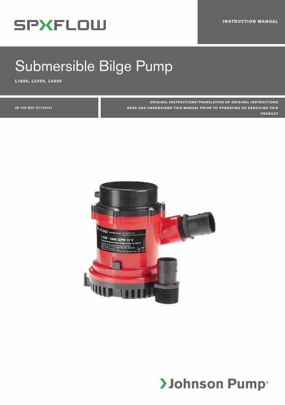
Dränkbar länspump L1600, L2200 och L4000, 12/24 VDränkbar länspump för pumpning av länsvatten i marin miljö. Installeras i kölsvinet.
5Översättning av originalinstruktionerna
> Svenska
RengöringKontrollera regelbundet om filtret och impellern blivit igensatta av smuts. För att kunna göra rent, tryck in låstapparna och lyft pumphuset. Obs! Utloppsslangen behöver inte tas bort vid rengöring.
TillbehörStrömbrytarpanel 12 eller 24 VArt nr: (EU) 12 V – 34-1224 (USA) 82044 24 V – 34-1225 82044-24
Elektrisk installation med SPX Johnson Pump strömbrytarpanelInstallera enligt kopplingsschemat på sid 16-17.
Automatisk nivåströmbrytare Art nr: (EU) 34-888 (USA) 26014
Avfallshantering/materialåtervinningVid avfallshantering ska produkten lämnas för destruktion/återvinning enligt gällande lagstiftning. Vid till-lämpliga fall demonteras och sorteras produkten i ingående materialfraktioner.
4. Montera filtret. Använd rostfria skruvar vid montering på trä. Ska pumpen monteras på metall eller glasfiber, skruva först fast en träplatta att fästa filtret på.5. Placera pumpen på filtret och se till att båda låstapparna ”snäpper” fast. 6. Välj en plats där vattnet ska pumpas överbord – så högt som möjligt över vattenlinjen och så nära pumpen som möjligt. Installera en 28 mm (1¹⁄8") [L1600/L2200] alt 38 mm (1½")[L2200/L4000] alt 50 mm (2")[L4000] bordgenomföring. OBS! L4000 pumpen leve- reras med en avtagbar backventil för att minimera återflöde av vatten. Om vattnet står en längre tid i slangen kommer lite vatten att sippra tillbaka. Backventilen minskar även flödet till en viss del.7. Anslut en 28 mm (1¹⁄8")[L1600/L2200] alt 38 mm (1½")[L2200/L4000] alt 50 mm (2")
[L4000] bränslesäker slang från pumpens utlopp till bordgenomföringen. Undvik skarpa veck och öglor. Om nödvändigt, fäst slangen. Obs! För att förhindra luftfickor är det viktigt att slangen inte riktas nedåt vid pumpens utlopp. Slangen ska hela tiden riktas uppåt.
8. Anslut den bruna kabeln till batteriets pluspol (+) och den svarta till batteriets minuspol (-) eller jord. Se kopplingsschema sid 16-18.
9. Viktigt! Alla elledningar måste klammas med kabelskarvarna så högt över länsvattnet som möjligt. Ta inte bort mer än nödvändigt av kabelisoleringen. Samtliga kabelskarvar ska tätas med ett marint tätningsmedel för att förhindra oxidation.
6 Original instructions
> English
Security• Thepumpmaynotbeusedforother liquids than water/bilge water. • Alwaysinstallthepumpaccordingtothe wiring diagram, see page 16-18.• Alwaysusethefuserequired,see ”Design features” below.• Thewireconnectionsmustbesealedwith a marine sealant.• Insulationorcablesheathingsmustbe placed above the highest bilge water level.• Donotrundry.
InstallationPlease follow the installation instructions carefully to assure maximum efficiency in your bilge pump operation.1. Remove the strainer from the bottom of the pump by depressing the lock tabs on both sides of the pump.2. Determine the desired location for the pump. Usually it is placed in the lowest point of the bilge.
Wire size: 1,5mm2 1,5mm2 14 Gage Max height: 149mm 177mm 216mm Max dia: 108mm 108mm 121mmWeight: 1,3 kg 2,25 kg 2,45kg
Submersible bilge pump L1600, L2200 and L4000, 12/24 VSubmersible bilge pump for pumping bilge water in marine environment. To be installed in the keelson.
Type designationPumptype Part nr (EU) (USA) L1600 12 V 32-1600-01 16004-00L1600 24 V 32-1600-02 16084-00 L2200 12 V 32-2200-01 22004L2200 24 V 32-2200-02 22084 L4000 12 V 32-4000-01 40004L4000 24 V 32-4000-02 40084
7Original instructions
> English
MaintenanceRegularly check the pump to be sure that the filter base and impeller are not clogged with debris. To clean, push in the tabs and lift up the pump housing. Note! The discharge hose need not be removed.
AccessoriesPanel 12 or 24 VPart No: (EU) 12 V – 34-1224 (USA) 82044 24 V – 34-1225 82044-24
Electrical installation with the SPX Johnson Pump panelAlways install according to the wiring diagram on page 16-18.
Automatic Float Switch Part No: (EU) 34-888 (USA) 26014
Waste handling & material recyclingAt the products end of life, please dispose of the product according to applicable law. Where applicable, please disassemble the product and recycle the parts material.
3. Position the strainer so that the pump nozzle is in the proper position to connect to the discharge hose.4. Mount the strainer. If attaching the strainer to wood, fasten with stainless steel screws. If attaching the strainer to metal or fiberglass, first mount a wooden block and then fasten the strainer to the wooden block.5. Mount the pump on the strainer so that both locktabs ”snaps” into place.6. Select a point where the bilge water is to be pumped overboard as high as possible above the water line and at the shortest distance from the pump. Install a 1½"[L2200/ L4000] or 1¹⁄8" [L1600/L2200] or 2"[L4000] thru-hull fitting. Note: The L4000 pump comes equipped with an integrated check valve to minimize back flow of water, however, over time water will seep back into the hull when the pump is not running. The use of flapper check valve will reduce maximum flow performance. 7. Fasten a 1½"[L2200/L4000] or 1¹⁄8" [L1600/L2200] or 2"[L4000] fuel resistant hose from the pump outlet to the thru-hull fitting. Avoid sharp bends or loops. Support the hose if necessary. Note: In order to prevent air locks it is important that the hose not be allowed to dip below the pump outlet. The hose should be constantly rising.8. Connect the brown wire to the positive (+) terminal of the battery, and the black wire to the negative (-) termal of the battery. See wiring diagram, page 16-17.9. Important: All electrical wiring must be clamped with the connections well above the bilge water level. Do not remove the insulation more than necessary. All wiring connec- tions should be sealed with a marine sealant to avoid oxidation.
8 Übersetzung der Original-Betriebanleitungen
> Deutsch
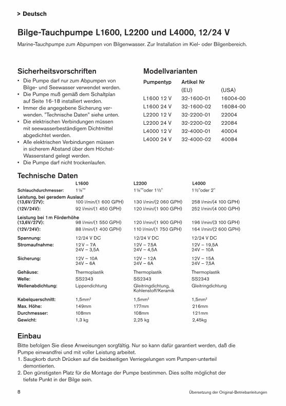
Sicherheitsvorschriften• Die Pumpe darf nur zum Abpumpen von Bilge- und Seewasser verwendet werden.• Die Pumpe muß gemäß dem Schaltplan auf Seite 16-18 installiert werden.• Immer die angegebene Sicherung ver- wenden. ”Technische Daten” siehe unten.• Die elektrischen Verbindungen müssen mit seewasserbeständigem Dichtmittel abgedichtet werden.• Alle elektrischen Verbindungen müssen in sicherem Abstand über dem Höchst- Wasserstand gelegt werden.• DiePumpedarfnichttrockenlaufen.
EinbauBitte befolgen Sie diese Anweisungen sorgfältig. Nur so kann dafür garantiert werden, daß die Pumpe einwandfrei und mit voller Leistung arbeitet.1. Saugkorb durch Drücken auf die beidseitigen Verriegelungen vom Pumpen-unterteil demontierten. 2. Den günstigsten Platz für die Montage der Pumpe bestimmen. Dies sollte möglichst der tiefste Punkt in der Bilge sein.
Max. Höhe: 149mm 177mm 216mm Durchmesser: 108mm 108mm 121mmGewicht: 1,3 kg 2,25 kg 2,45kg
ModellvariantenPumpentyp Artikel Nr (EU) (USA) L1600 12 V 32-1600-01 16004-00L1600 24 V 32-1600-02 16084-00 L2200 12 V 32-2200-01 22004L2200 24 V 32-2200-02 22084 L4000 12 V 32-4000-01 40004L4000 24 V 32-4000-02 40084
Bilge-Tauchpumpe L1600, L2200 und L4000, 12/24 VMarine-Tauchpumpe zum Abpumpen von Bilgenwasser. Zur Installation im Kiel- oder Bilgenbereich.
9Übersetzung der Original-Betriebanleitungen
> Deutsch
ModellvariantenPumpentyp Artikel Nr (EU) (USA) L1600 12 V 32-1600-01 16004-00L1600 24 V 32-1600-02 16084-00 L2200 12 V 32-2200-01 22004L2200 24 V 32-2200-02 22084 L4000 12 V 32-4000-01 40004L4000 24 V 32-4000-02 40084
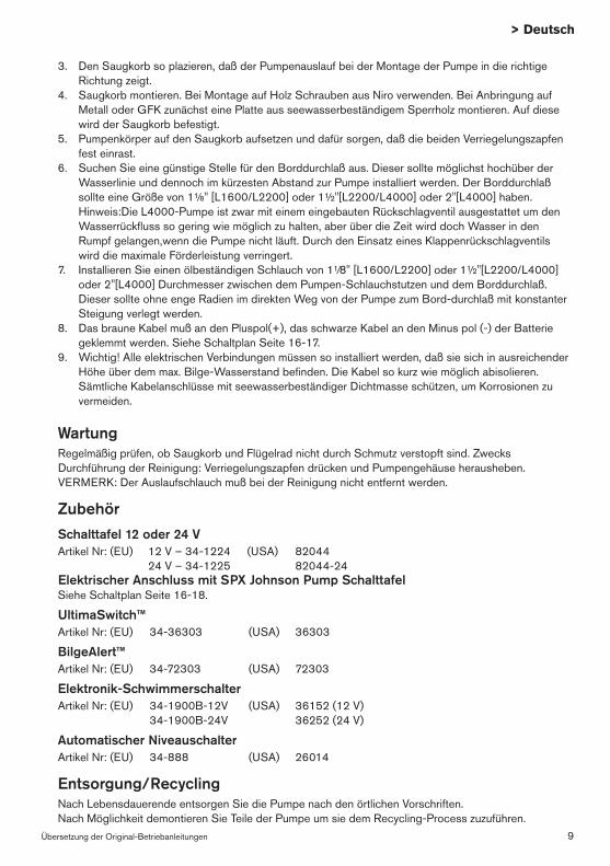
WartungRegelmäßig prüfen, ob Saugkorb und Flügelrad nicht durch Schmutz verstopft sind. Zwecks Durchführung der Reinigung: Verriegelungszapfen drücken und Pumpengehäuse herausheben. VERMERK: Der Auslaufschlauch muß bei der Reinigung nicht entfernt werden.
ZubehörSchalttafel 12 oder 24 VArtikel Nr: (EU) 12 V – 34-1224 (USA) 82044 24 V – 34-1225 82044-24 Elektrischer Anschluss mit SPX Johnson Pump SchalttafelSiehe Schaltplan Seite 16-18.
Entsorgung/Recycling Nach Lebensdauerende entsorgen Sie die Pumpe nach den örtlichen Vorschriften. Nach Möglichkeit demontieren Sie Teile der Pumpe um sie dem Recycling-Process zuzuführen.
3. Den Saugkorb so plazieren, daß der Pumpenauslauf bei der Montage der Pumpe in die richtige Richtung zeigt.
4. Saugkorb montieren. Bei Montage auf Holz Schrauben aus Niro verwenden. Bei Anbringung auf Metall oder GFK zunächst eine Platte aus seewasserbeständigem Sperrholz montieren. Auf diese wird der Saugkorb befestigt.
5. Pumpenkörper auf den Saugkorb aufsetzen und dafür sorgen, daß die beiden Verriegelungszapfen fest einrast.
6. Suchen Sie eine günstige Stelle für den Borddurchlaß aus. Dieser sollte möglichst hochüber der Wasserlinie und dennoch im kürzesten Abstand zur Pumpe installiert werden. Der Borddurchlaß sollte eine Größe von 1¹⁄8" [L1600/L2200] oder 1½"[L2200/L4000] oder 2"[L4000] haben. Hinweis:Die L4000-Pumpe ist zwar mit einem eingebauten Rückschlagventil ausgestattet um den Wasserrückfluss so gering wie möglich zu halten, aber über die Zeit wird doch Wasser in den Rumpf gelangen,wenn die Pumpe nicht läuft. Durch den Einsatz eines Klappenrückschlagventils wird die maximale Förderleistung verringert.
7. Installieren Sie einen ölbeständigen Schlauch von 1¹⁄8" [L1600/L2200] oder 1½"[L2200/L4000] oder 2"[L4000] Durchmesser zwischen dem Pumpen-Schlauchstutzen und dem Borddurchlaß. Dieser sollte ohne enge Radien im direkten Weg von der Pumpe zum Bord-durchlaß mit konstanter Steigung verlegt werden.
8. Das braune Kabel muß an den Pluspol(+), das schwarze Kabel an den Minus pol (-) der Batterie geklemmt werden. Siehe Schaltplan Seite 16-17.
9. Wichtig! Alle elektrischen Verbindungen müssen so installiert werden, daß sie sich in ausreichender Höhe über dem max. Bilge-Wasserstand befinden. Die Kabel so kurz wie möglich abisolieren. Sämtliche Kabelanschlüsse mit seewasserbeständiger Dichtmasse schützen, um Korrosionen zu vermeiden.
10 Traduction du manuel d'instruction d'origine
> Français
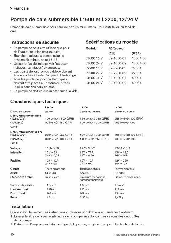
Instructions de sécurité• Lapompenepeutêtreutiliséequepour de l’eau ou pour les eaux de cale.• Branchertoujourslapompeselonle schéma électrique, page 16-18.• Utiliserlefusibleindiqué,voir”caracté- ristiques techniques” ci-dessous.• Lespointsdejonctionducablagedoivent être étanchés à l’aide d’un produit hydrofuge.• Touslespointsdejonctionélectriques doivent être placés au-dessus du niveau le plus haut des eaux de cale.• Lapompenedoitenaucuncastourneràvide.
InstallationSuivre méticuleusement les instructions ci-dessous afin d’obtenir un rendement optimum.1. Enlever le filtre de la partie inférieure de la pompe en enfonçant les verrous des deux côtés de la pompe.2. Déterminer l’emplacement de montage de la pompe, en général au point le plus bas de la cale.
Section de câbles: 1,5mm2 1,5mm2 1,5mm2 Hauteur maxi: 149mm 177mm 216mm Diam. maxi: 108mm 108mm 121mmPoids: 1,3 kg 2,25 kg 2,45kg
Pompe de cale submersible L1600 et L2200, 12/24 VPompe de cale submersible pour eaux de cale en milieu marin. Pour installation en fond de cale.
Spécifications du modèleModèle Référence (EU) (USA)L1600 12 V 32-1600-01 16004-00L1600 24 V 32-1600-02 16084-00 L2200 12 V 32-2200-01 22004L2200 24 V 32-2200-02 22084 L4000 12 V 32-4000-01 40004L4000 24 V 32-4000-02 40084
11Traduction du manuel d'instruction d'origine
> Français
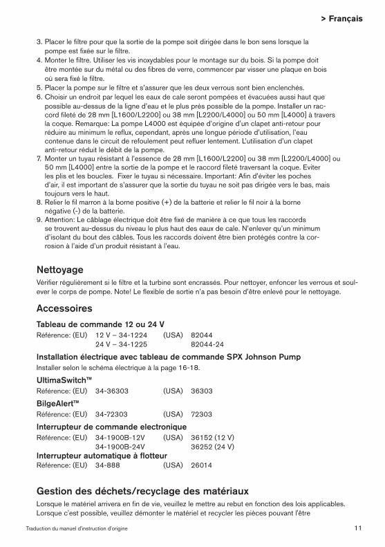
NettoyageVérifier régulièrement si le filtre et la turbine sont encrassés. Pour nettoyer, enfoncer les verrous et soul-ever le corps de pompe. Note! Le flexible de sortie n’a pas besoin d’être enlevé pour le nettoyage.
AccessoiresTableau de commande 12 ou 24 VRéférence: (EU) 12 V – 34-1224 (USA) 82044 24 V – 34-1225 82044-24
Installation électrique avec tableau de commande SPX Johnson PumpInstaller selon le schéma électrique à la page 16-18.
Gestion des déchets/recyclage des matériauxLorsque le matériel arrivera en fin de vie, veuillez le mettre au rebut en fonction des lois applicables. Lorsque c'est possible, veuillez démonter le matériel et recycler les pièces pouvant l'être
3. Placer le filtre pour que la sortie de la pompe soit dirigée dans le bon sens lorsque la pompe est fixée sur le filtre.4. Monter le filtre. Utiliser les vis inoxydables pour le montage sur du bois. Si la pompe doit être montée sur du métal ou des fibres de verre, commencer par visser une plaque en bois où sera fixé le filtre.5. Placer la pompe sur le filtre et s’assurer que les deux verrous sont bien enclenchés. 6. Choisir un endroit par lequel les eaux de cale seront pompées et évacuées aussi haut que possible au-dessus de la ligne d’eau et le plus près possible de la pompe. Installer un rac- cord fileté de 28 mm [L1600/L2200] ou 38 mm [L2200/L4000] ou 50 mm [L4000] à travers la coque. Remarque: La pompe L4000 est équipée d’origine d’un clapet anti-retour pour réduire au minimum le reflux, cependant, après une longue période d’utilisation, l’eau contenue dans le circuit de refoulement peut refluer lentement. L’utilisation d’un clapet anti-retour réduit le débit de la pompe.7. Monter un tuyau résistant à l’essence de 28 mm [L1600/L2200] ou 38 mm [L2200/L4000] ou 50 mm [L4000] entre la sortie de la pompe et le raccord fileté traversant la coque. Eviter les plis et les boucles. Fixer le tuyau si nécessaire. Important: Afin d’éviter les poches d’air, il est important de s’assurer que la sortie du tuyau ne soit pas dirigée vers le bas, mais toujours vers le haut.8. Relier le fil marron à la borne positive (+) de la batterie et relier le fil noir à la borne négative (-) de la batterie.9. Attention: Le câblage électrique doit être fixé de manière à ce que tous les raccords se trouvent au-dessus du niveau le plus haut des eaux de cale. N’enlever qu’un minimum d’isolant du bout des câbles. Tous les raccords doivent être bien protégés contre la cor- rosion à l’aide d’un produit résistant à l’eau.
12 Traducción de instrucciones originales
> Español
Instrucciones de seguridad• Labombasólodebeutilizarseparaagua.• Instalarlabombasegúnelesquemaeléc- trico de las páginas 16-18.• Ponerelfusibleindicadoen”Caracterís- ticas técnicas”.• Todaslasconexioneseléctricasdeben sellarse con silicona marina.• Todaslasconexioneseléctricasdeben quedar por encima del nivel más alto de la sentina.• Nodebefuncionarenseco.
InstalaciónSe recomienda observar estrictamente estas instrucciones para asegurar la máxima eficacia de la bomba.1. Quitar el filtro de la parte inferior de la bomba presionando los ejes de cierre a ambos lados de la bomba.2. Determinar el lugar de montaje de la bomba. Generalmente se coloca en el punto más bajo de la sentina.
Conductor: 1,5mm2 1,5mm2 1,5mm2 Alto total: 149mm 177mm 216mm Ø total: 108mm 108mm 121mmPeso: 1,3 kg 2,25 kg 2,45kg
Bomba de achique sumergible L1600, L2200 y L4000, 12/24 VBomba de achique sumergible para achicar agua en ambientes marinos. Para instalación en la contra-quilla.
ModeloTipo Ref. No (EU) (USA)L1600 12 V 32-1600-01 16004-00L1600 24 V 32-1600-02 16084-00 L2200 12 V 32-2200-01 22004L2200 24 V 32-2200-02 22084 L4000 12 V 32-4000-01 40004L4000 24 V 32-4000-02 40084
13Traducción de instrucciones originales
> Español
MantenimientoComprobar regularmente si el filtro y el impulsor están obturados por suciedad. Para limpiarlos, presionar los pernos de cierre y quitar la bomba. Nota: No es necesario quitar la manguera.
AccesoriosPanel 12 ó 24 VRef. No: (EU) 12 V – 34-1224 (USA) 82044 24 V – 34-1225 82044-24
Instalación eléctrica con el panel de SPX Johnson PumpInstalar según el esquema eléctrico de la página 16-18.
UltimaSwitch™Ref. No: (EU) 34-36303 (USA) 36303
BilgeAlert™Ref. No: (EU) 34-72303 (USA) 72303
Interruptor de nivel electrónicoRef. No: (EU) 34-1900B-12V (USA) 36152 (12 V) 34-1900B-24V 36252 (24 V)
Desguace/RecicladoAl final de la vida del equipo disponga de este de acuerdo a la ley. Donde sea de aplicación desmonte el equipo y recicle los diferentes materiales.
3. Colocar el filtro de manera que la salida de la bomba quede orientada para conectar la manguera.4. Montar el filtro. Utilizar tornillos de acero inoxidable si se hace el montaje sobre madera. Si la bomba se ha de montar sobre metal o fibra de vidrio, deberá colocarse una chapa de madera a la que se fijará el filtro.5. Colocar la bomba en el filtro y asegurarse que los dos pernos de cierre quedan bien encajados.6. Elegir un punto en que la salida del agua esté a la mayor distancia posible por encima de la línea de flotación y lo más cerca de la bomba. Nota: La bomba del L4000 viene provista de una válvula de control integrada que merma el caudal de retorno del agua, sin em- bargo, con el tiempo el agua vuelve a filtrarse en el casco cuando la bomba no trabaja. El uso de la válvula de retención reducirá al máximo la acción del flujo.7. Fijar la manguera de 1½"[L2200/L4000] ó 1¹⁄8"[L1600/L2200] ó 2"[L4000] resistente a hidrocarburos, entre la bomba y el pasacascos. Evitar coca y lazos. Si fuese necesario, fijar la manguera. Observación: Para evitar la entrada de aire, es importante que la manguera no quede por debajo de la salida de la bomba. La manguera debe tener una elevación constante.8. Conectar el cable marrón al positivo (+) y el cable negro al negativo (-).9. Importante: Todo el cableado debe fijarse de manera que las conexiones queden lo más alto posible por encima del nivel de agua de la sentina. Pelar los cables justo lo imprescin- dible. Todas las conexiones deben aislarse con silicona marina para evitar la corrosión.
14 Traduzione delle istruzioni originali
> Italiano
Istruzioni di sicurezza• Lapompanosipuòusareperaltriliquidi dell’acqua o dell’acqua di sentina.• Installaresemprelapompasecondoil schema elettrico nella pagina 16-18.• Usareilfusibileindicato,vederelecarat- teristiche tecniche in basso.• Icollegamentielettricidovrebberoessere sigillati con un sigillante marino. • Tuttiicollegamentielettricidevonoessere posti al di sopra del livello più alto dell’acqua.• Lapompanopuógirareavuoto.
InstallazioneSi prega di seguire con attenzione le istruzioni di montaggio per garantire la massima efficacia di funzionamento alla vostra pompa di sentina.1. Rimuovere il filtro dalla parte inferiore della pompa, premendo all’interno entrambi i perni di bloccaggio posti ai lati della pompa stessa.2. Individuare il punto in cui installare la pompa, solitamente quello più basso della sentina.
Corpo: Termoplastico Termoplastico Termoplastico Albero: SS2343 SS2343 SS2343 Guarnizione dell'albero: Guarnizioni a labbro Tenuta meccanica, Tenuta meccanica, carbonio/ceramica Area cavo: 1,5mm2 1,5mm2 1,5mm2 Altezza: 149mm 177mm 216mm Dimenzione: 108mm 108mm 121mmPeso: 1,3 kg 2,25 kg 2,45 kg
Specifica del tipoTipo Art No (EU) (USA)L1600 12 V 32-1600-01 16004-00L1600 24 V 32-1600-02 16084-00 L2200 12 V 32-2200-01 22004L2200 24 V 32-2200-02 22084 L4000 12 V 32-4000-01 40004L4000 24 V 32-4000-02 40084
Pompa di sentina sommersa L1600, L2200 a L4000, 12/24 VPompa di sentina sommersa per pompare l’acqua di sentina in ambiente marino. Per installazione in stiva.
15Traduzione delle istruzioni originali
> Italiano
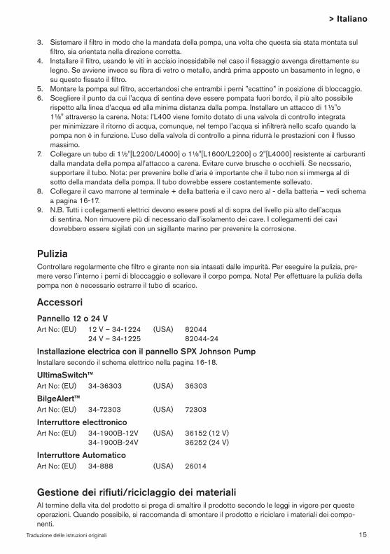
PuliziaControllare regolarmente che filtro e girante non sia intasati dalle impurità. Per eseguire la pulizia, pre-mere verso l’interno i perni di bloccaggio e sollevare il corpo pompa. Nota! Per effettuare la pulizia della pompa non è necessario estrarre il tubo di scarico.
AccessoriPannello 12 o 24 VArt No: (EU) 12 V – 34-1224 (USA) 82044 24 V – 34-1225 82044-24
Installazione electrica con il pannello SPX Johnson PumpInstallare secondo il schema elettrico nella pagina 16-18.
Gestione dei rifiuti/riciclaggio dei materialiAl termine della vita del prodotto si prega di smaltire il prodotto secondo le leggi in vigore per queste operazioni. Quando possibile, si raccomanda di smontare il prodotto e riciclare i materiali dei compo-nenti.
3. Sistemare il filtro in modo che la mandata della pompa, una volta che questa sia stata montata sul filtro, sia orientata nella direzione corretta.
4. Installare il filtro, usando le viti in acciaio inossidabile nel caso il fissaggio avvenga direttamente su legno. Se avviene invece su fibra di vetro o metallo, andrà prima apposto un basamento in legno, e su questo fissato il filtro.
5. Montare la pompa sul filtro, accertandosi che entrambi i perni ”scattino” in posizione di bloccaggio.6. Scegliere il punto da cui l’acqua di sentina deve essere pompata fuori bordo, il più alto possibile
rispetto alla linea d’acqua ed alla minima distanza dalla pompa. Installare un attacco di 1½"o 1¹⁄8" attraverso la carena. Nota: l’L400 viene fornito dotato di una valvola di controllo integrata per minimizzare il ritorno di acqua, comunque, nel tempo l’acqua si infiltrerà nello scafo quando la pompa non è in funzione. L’uso della valvola di controllo a pinna ridurrà le prestazioni con il flusso massimo.
7. Collegare un tubo di 1½"[L2200/L4000] o 1¹⁄8"[L1600/L2200] o 2"[L4000] resistente ai carburanti dalla mandata della pompa all’attacco a carena. Evitare curve brusche o occhielli. Se necssario, supportare il tubo. Nota: per prevenire bolle d’aria è importante che il tubo non si immerga al di sotto della mandata della pompa. Il tubo dovrebbe essere costantemente sollevato.
8. Collegare il cavo marrone al terminale + della batteria e il cavo nero al - della batteria – vedi schema a pagina 16-17.
9. N.B. Tutti i collegamenti elettrici devono essere posti al di sopra del livello più alto dell’acqua di sentina. Non rimuovere più di necessario dall’isolamento dei cave. I collegamenti dei cavi dovrebbero essere sigilati con un sigillante marino per prevenire la corrosione.
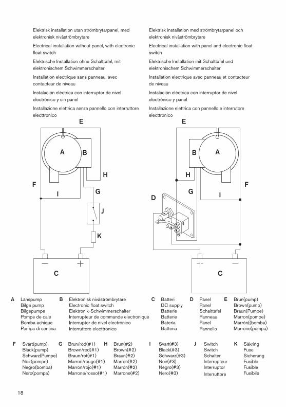
A Länspump Bilge pump Bilgepumpe Pompe de cale Bomba achique Pompa di sentina
C Batteri DC supply Batterie Batterie Batería Batteria
B Elektronisk UltimaSwitch Electronic UltimaSwitch Elektronik UltimaSwitch Interrupteur UltimaSwitch Interruptor UltimaSwitch Interruttore UltimaSwitch
E Brun(pump) Brown(pump) Braun(Pumpe) Marron(pompe) Marrón((bomba) Marrone(pompa)
F Svart(pump) Black(pump) Schwarz(Pumpe) Noir(pompe) Negro(bomba) Nero(pompa)
H Brun/vit(#2) Brown/white(#2) Braun/weiss(#2) Marron/blanc(#2) Marrón/blanco(#2) Marrone/bianco(#2)
G Brun(#1) Brown(#1) Braun(#1) Marron(#1) Marrón(#1) Marrone(#1)
Elektrisk installation med strömbrytarpanel.Electrical installation with panel.
Elektrische Installation mit Schalttafel.
Installation electrique avec panneau.
Instalación eléctrica con panel.
Installazione elettrica con pannello.
Elektrisk installation utan strömbrytarpanel.
Electrical installation without panel.
Elektrische Installation ohne Schalttafel.
Installation electrique sans panneau
Instalación eléctrica sin panel
Installazione elettrica senza pannello
UltimaSwitch
Obs: Dessa kablar är redan anslutna Note: These cables are already connected Wichtig: Kabeln schon angeschlossen Important: Ces câbles sont déjà raccordés Advertencia: Estos cables ya van conectados Nota Bene: Questi cavi sono già collegati
+ -
D
A
C
Brun, nr 2Brown, No 2 Braunes, Nr. 2Marron, No 2Marrón, No 2Marrone, No 2
Brun/vit, nr 1Brown/white, No 1 Braunes/weiss, Nr. 1Marron/blanc, No 1Marrón/blanco, No 1Marrone/blanco, No 1
A Länspump Bilge pump Bilgepumpe Pompe de cale Bomba achique Pompa di sentina
Elektrisk installation med strömbrytarpanel och elektronisk nivåströmbrytare
Electrical installation with panel and electronic float switch
Elektrische Installation mit Schalttafel und elektronischem Schwimmerschalter
Installation electrique avec panneau et contacteur de niveau
Instalación eléctrica con interruptor de nivel electrónico y panel
Installazione elettrica con pannello e interrutore electtronico
C Batteri DC supply Batterie Batterie Batería Batteria
Elektrisk installation utan strömbrytarpanel, med elektronisk nivåströmbrytare
Electrical installation without panel, with electronic float switch
Elektrische Installation ohne Schalttafel, mit elektronischem Schwimmerschalter
Installation electrique sans panneau, avec contacteur de niveau
Instalación eléctrica con interruptor de nivel electrónico y sin panel
Installazione elettrica senza pannello con interruttore electtronico
B Elektronisk nivåströmbrytare Electronic float switch Elektronik-Schwimmerschalter Interrupteur de commande electronique Interruptor de nivel electrónico Interruttore electtronico
E Brun(pump) Brown(pump) Braun(Pumpe) Marron(pompe) Marrón((bomba) Marrone(pompa)
F Svart(pump) Black(pump) Schwarz(Pumpe) Noir(pompe) Negro(bomba) Nero(pompa)
H Brun(#2) Brown(#2) Braun(#2) Marron(#2) Marrón(#2) Marrone(#2)
G Brun/röd(#1) Brown/red(#1) Braun/rot(#1) Marron/rouge(#1) Marrón/rojo(#1) Marrone/rosso(#1)
I Svart(#3) Black(#3) Schwarz(#3) Noir(#3) Negro(#3) Nero(#3)