Amenities from Technology for People and the Earth Printed on recycled paper with soy ink - Evidence of our commitment to the environment Submersible Resin Pumps Submersible Resin Pumps PU/PN/PSF/PLS/TM/OM
Transcript
Amenities from Technology for People and the Earth
Printed on recycled paper with soy ink -Evidence of our commitment to the environment
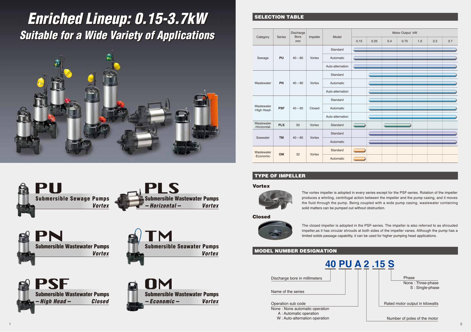
The vortex impeller is adopted in every series except for the PSF-series. Rotation of the impellerproduces a whirling, centrifugal action between the impeller and the pump casing, and it movesthe fluid through the pump. Being coupled with a wide pump casing, wastewater containingsolid matters can be pumped out without obstruction.
The closed impeller is adopted in the PSF-series. The impeller is also referred to as shroudedimpeller,as it has circular shrouds at both sides of the impeller vanes. Although the pump has alimited solids passage capability, it can be used for higher pumping head applications.
Vortex
Closed
Discharge bore in millimeters
Name of the series
Operation sub codeNone : None automatic operation A : Automatic operation W : Auto-alternation operation
PhaseNone : Three-phase S : Single-phase
Rated motor output in kilowatts
Number of poles of the motor
SELECTION TABLE
TYPE OF IMPELLER
MODEL NUMBER DESIGNATION
21
Enriched Lineup: 0.15-3.7kWSuitable for a Wide Variety of ApplicationsEnriched Lineup: 0.15-3.7kW
Suitable for a Wide Variety of Applications
The TOK guide rail fitting system connects the pump to and from the piping easily just by lowering and hoisting the pump, allowing easy maintenance and inspection without the need to enter the sump.
Made of high-quality resin, the TOK is designed for lightweight, small to middle sized pumps. Rubber bellows attached to the guide hook are inverted to the duckfoot bend when the pump starts operating, and it seals by the pumping pressure. This eliminates leakage at the seal even if a lightweight pump is used in combination with the TOK.
The TOK is available in all motor output ranges of the PU, PN, and PSF series.
Automatic ModelThe float type automatic model has an integral control circuit and two float switches that operate at a low voltage. It operates automatically in response to the change in water levels.
This model can be identified by the suffix "A" and is availa-ble in all motor output ranges of the PU, PN, PSF, and TM series.
The cylindrical float type automatic model is available only for the OM-series. Adoption of the unique float switch has made even the automatic model very compact and enables it to be installed in a limited space. Automatic operation is possible with a simple power panel.
Auto-alternation ModelThe auto-alternation model is used along with an automatic model. The combinational use of these two pumps enables each pump to operate alter-nately without control panel.
The auto-alternation model has three floats and can be identified by the suffix “W”.Refer to model selection for availability and model num-bers of the PU, PN, and PSF series.
1
4
2
35
“A” Unit “W” Unit
Primary Operation Secondary Operation
1 1
2 2
3 3
1
4
2
3
5
1
4
2
35
“A” Unit “W” Unit
1
4
2
3
5
1
4
2
3
5
1
4
2
35
1
4
2
3
5
1
4
2
3
5
UnusualIncrease ofInflow
UnusualIncrease ofInflow
Water level rises and turns the Float #2 up. The Float #2 is activated but the pump does not start. When water level r ises to Float #3 and the f loat is activated, the “W” unit starts.
The next time the water level rises, Float #1 on the “A” unit is activated but the unit does not start until Float #4 is activated.
When water level falls to Float #2, the float is activated, and the “W” unit stops. The alternating circuitry deactivates the “W” unit for the next level rise.
When water level falls and Float #1 is activated, the “A” unit stops. At the same time, “W” unit becomes ready for operation for the next level rise.
If inflow exceeds the capacity of “W” unit and the water level rises to Float #4, “A” unit starts.
If inflow exceeds the capacity of “A” unit and the water level rises to Float #5, “W” unit starts.
The “W” unit is discharging water (Water level falls). The “A” unit is discharging water (Water level falls).
Lifting Chain(with Shackles)
Guide Hook
Guide Pipe(not supplied)
Screwed Flange
Duckfoot Bend
Guide Support(with Bolt & Nuts)
Practical Design ProvidingExcellent Corrosion Resistance and Durability
Practical Design ProvidingExcellent Corrosion Resistance and Durability
Cable
Gland
Anti-wickingBlock
Miniature Thermal Protector Circle Thermal Protector
1. Anti-wicking Cable EntryEvery cabtyre cable has an anti-wicking block at the cable entry section on the pump.This mechanism is such that a part of each conductor is stripped back and the part is sealed by molded rubber or epoxy potting which has flowed in between each strand of the conductor. This unique feature prevents wicking along the strand of the conductor itself.
2. Motor ProtectorA built-in thermal motor protection device reacts to the excessive heat caused by overcurrent or run-dry conditions. It not only cuts off the motor circuit automatically but also resets by itself. When the motor cools down to a safe operating temperature, the motor restarts.
3. BearingsHigh-grade bearings for high-temperature operation are used. Also, as deep-groove, double-shielded C3 ball bearings are used, and as the bearings are permanently lubricated by grease, there is no need for injection of lubricating oil.
4. Lubricating OilLiquid paraffin is used in every VANCSseries pump. It is a highly-refined pure oil generally used in the industries of cosmetic, pharmaceutical, and food processing equipment, etc. The use of this oil widens the applications of the pumps to decorative waterfalls, fishponds, and aquaculture, etc.
6. Oil Lifter (Patented) * Not Available for OM-series
The Oil Lifter was developed as a lubricating device for the mechanical seal. Utilizing the centrifugal force of the shaft seal, the Oil Lifter forcibly supplies lubricating oil to the mechan-ical seal and continues to supply the oil to the upper seal faces even if lubricant falls below the rated volume. This amazingly simple device is not only reliably lubricates and cools down, but also retains the stable shaft seal effect and extends the inspection term.
9. Rubber FootA rubber foot is fitted on each stand of the pumps from 1.5 to 3.7kW and the PLS-series pumps. This prevents scratching of floor surface.
5. Dual Inside Mechanical SealA mechanical seal with two seal faces containing silicon carbide (SiC) is equipped with the oil chamber. The advantages of the seal are two-fold, it eliminates spring failure caused by corrosion, abrasion or fouling which prevents the seal faces from closing properly, and prevents loss of cooling to the lower seal faces during run-dry conditions which causes the lower seal faces to fail.
8. Back Pull-out Design * Not Available for OM-series
Unfastening the bolts between the oil casing and the upper pump casing allows the body to be separated into the pump section and the motor section with the impeller left in position. This facilitates easier inspections of the main portions.The pump section can be disassembled/reassembled using a cross slot screwdriver (excluding 0.15kW).
7. Air Release Valve * Not Available for PLS-series
In order to prevent “air lock”, an air release valve is built in the pump casing. The valve is similar to a ball check valve. When air goes through the valve, the ball stays at the bottom, but when the pumped water starts to flow, it closes the outlet by its buoyancy.
1
2
4
8
3
6
5
7
9
43
Oil
ShaftOil Lifter
Upper Seal Faces
Guide VaneMechanical Seal
TOK GUIDE RAIL FITTING SYSTEM
AUTOMATIC & AUTO-ALTERNATION MODEL
How the Auto-alternation Model Works
• Weights excluding cable
TOK4-PTOK2-65TOK2-65T
0.15 to 0.75kW1.5kW2.2 to 3.7kW
Model
Model d A B H W1 W2
MaterialLength100-120VCores ×
mm2Outer Dia.
mmCores ×
mm2Outer Dia.
mm
200-240V
m
Model Applicable Motor Output
DischargeBore
MotorOutput Phase Starting
MethodSolids
Passage Dry Weight kgModel
Standard Automatic StandardAuto-alternation Auto &Auto-alternation
PVC
Unit: mm
PumpingFluid
Discharge Connection
Pump
Discharge Bore 50 8040mm
Motor
Sewage, Wastewater, andWater carrying Solid Matters0 to 40℃VortexDouble Mechanical Seal (with Oil Lifter)Double-shielded Ball BearingGlass-fiber Reinforced ResinGlass-fiber Reinforced ResinSilicon CarbideDry-type SubmersibleInduction Motor, 2-poleClass ESingle-phase (suffix "S")Three-phaseCapacitor Run (single-phase only)Direct on LineCircle Thermal ProtectorMiniature Thermal Protector(40PU2.15S, 40PU2.25S & 50PU2.4S only)
C.W.L.: Continuous Running Water LevelL.W.L.: Lowest Running Water Level
L.W.L.
C.W.L.
d
W2
W1 H
10
15
20
25
5
0 00.2 0.4 0.6 0.8 1.0
10
15
20
2527 27
5
0.2 0.4 0.6 0.8 1.0
Tota
l Hea
d (m
)
Tota
l Hea
d (m
)
Capacity (m /min)3 Capacity (m /min)3
S.S. 3000min-1 S.S. 3600min-1
80PU23.7
80PU22.2
80PU22.2
80PU21.5
80PU21.5
50PU2.75 (S )
50PU2.75 (S )
50PU2.4(S)
50PU2.4(S)40PU2.25(S)
40PU2.25(S)40PU2.15(S)
40PU2.15(S)
80PU23.7
80PU23.780PU22.2
80PU22.280PU21.5
80PU21.5
50PU2.75(S)
50PU2.75(S)
50PU2.4(S)
50PU2.4(S)40PU2.25(S)
40PU2.25(S)40PU2.15(S)
40PU2.15(S)
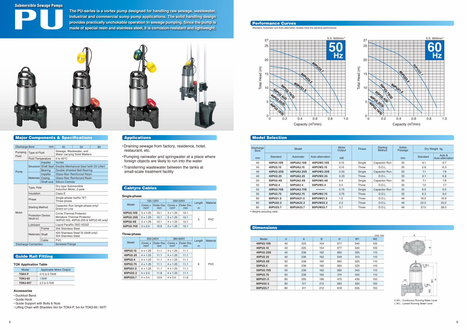
50Hz
60Hz
Standard, Automatic and Auto-alternation models have the identical performance.
0 0
Guide Rail Fitting
Model Selection
Performance Curves
Dimensions
Cabtyre Cables
The PU-series is a vortex pump designed for handling raw sewage, wastewater, Industrial and commercial sump pump applications. The solid handling design provides practically unchokable operation in sewage pumping. Since the pump is made of special resin and stainless steel, it is corrosion-resistant and lightweight.
Submersible Sewage Pumps
Accessories• Duckfoot Bend• Guide Hook• Guide Support with Bolts & Nuts • Lifting Chain with Shackles (4m for TOK4-P, 5m for TOK2-65 / 65T)
TOK Application Table
Applications
• Draining sewage from factory, residence, hotel, restaurant, etc.• Pumping rainwater and springwater at a place where foreign objects are likely to run into the water• Transferring wastewater between the tanks at small-scale treatment facility
Major Components & Specifications
Single-phase
Three-phase
65
• Weights excluding cable
TOK4-PTOK2-65TOK2-65T
0.25 to 0.75kW1.5kW2.2 to 3.7kW
Model d A B H W1 W2
Model Applicable Motor Output
DischargeBore
MotorOutput Phase Starting
MethodSolids
Passage Dry Weight kgModel
Standard Automatic StandardAuto-alternation Auto &Auto-alternation
Unit: mm
PumpingFluid
Discharge Connection
Pump
Discharge Bore 50 8040mm
Motor
Wastewater andWater carrying Small Solid Matters0 to 40℃VortexDouble Mechanical Seal (with Oil Lifter)Double-shielded Ball BearingGlass-fiber Reinforced ResinGlass-fiber Reinforced ResinSilicon CarbideDry-type SubmersibleInduction Motor, 2-poleClass ESingle-phase (suffix "S")Three-phaseCapacitor Run (single-phase only)Direct on LineCircle Thermal ProtectorMiniature Thermal Protector(40PN2.25S & 50PN2.4S only)
Liquid Paraffin (ISO VG32)304 Stainless Steel304 Stainless SteelPVCScrewed Flange
C.W.L.: Continuous Running Water LevelL.W.L.: Lowest Running Water Level
Capacity (m /min)3 Capacity (m /min)3
S.S. 3000min-1 S.S. 3600min-1
5
10
15
20
25
30
0.2 0.4 0.6 0.8 1.0
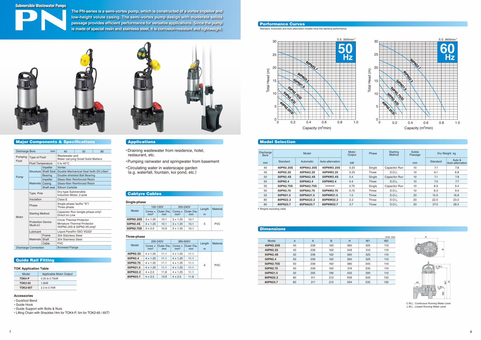
50Hz
40PN2.25(S)
40PN2.25(S)
50PN2.4 (S )
50PN2.4 (S )
50PN2.75(S)
50PN2.75(S)
50PN21.5
50PN21.5
80PN22.2
80PN22.2
80PN23.7
80PN23.7
60Hz
5
10
15
20
25
30
0.2 0.4 0.6 0.8 1.0
40PN2.25 (S )
40PN2.25 (S )
50PN2.4 (S )
50PN2.4 (S )
50PN2.75 (S )
50PN2.75 (S )
50PN21.5
50PN21.580PN22.2
80PN22.2
80PN23.7
80PN23.7
Standard, Automatic and Auto-alternation models have the identical performance.
00
00
Tota
l Hea
d (m
)
Tota
l Hea
d (m
)
Guide Rail Fitting
Model Selection
Performance Curves
Dimensions
Cabtyre Cables
The PN-series is a semi-vortex pump, which is constructed of a vortex impeller and low-height volute casing. The semi-vortex pump design with moderate solids passage provides efficient performance for versatile applications. Since the pump is made of special resin and stainless steel, it is corrosion-resistant and lightweight.
Submersible Wastewater Pumps
Accessories• Duckfoot Bend• Guide Hook• Guide Support with Bolts & Nuts • Lifting Chain with Shackles (4m for TOK4-P, 5m for TOK2-65 / 65T)
TOK Application Table
Applications
• Draining wastewater from residence, hotel, restaurant, etc.• Pumping rainwater and springwater from basement• Circulating water in waterscape garden (e.g. waterfall, fountain, koi pond, etc.)
Major Components & Specifications
87
B
A
L.W.L.
C.W.L.
d
W2
W1 H
• Weights excluding cable
TOK4-PTOK2-65TOK2-65T
0.25 to 0.75kW1.5kW2.2 to 3.7kW
Model d A B H W1 W2
Model Applicable Motor Output
DischargeBore
MotorOutput Phase Starting
MethodSolids
Passage Dry Weight kgModel
Standard Automatic StandardAuto-alternation Auto &Auto-alternation
Unit: mm
PumpingFluid
Discharge Connection
Pump
Discharge Bore 50 6540mm
Motor
Wastewater andWater carrying Few Solid Matters0 to 40℃ClosedDouble Mechanical Seal (with Oil Lifter)Double-shielded Ball BearingGlass-fiber Reinforced ResinGlass-fiber Reinforced ResinSilicon CarbideDry-type SubmersibleInduction Motor, 2-poleClass ESingle-phase (suffix "S")Three-phaseCapacitor Run (single-phase only)Direct on LineCircle Thermal ProtectorMiniature Thermal Protector(single-phase only)
Liquid Paraffin (ISO VG32)304 Stainless Steel304 Stainless SteelPVCScrewed Flange
C.W.L.: Continuous Running Water LevelL.W.L.: Lowest Running Water Level
Capacity (m /min)3 Capacity (m /min)3
S.S. 3000min-1 S.S. 3600min-1
60Hz
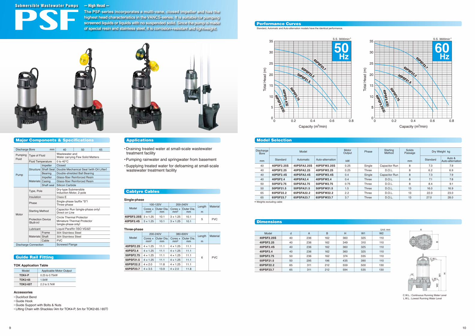
Standard, Automatic and Auto-alternation models have the identical performance.
0.2 0.4 0.6 0.8
10
5
15
20
25
30
35
50Hz
40PSF2.25 (S )
40PSF2.25 (S )40PSF2.4 (S )40PSF2.4 (S )
50PSF2.75
50PSF2.75
50PSF21.5
50PSF21.5
65PSF22.2
65PSF22.2
65PSF23.7
65PSF23.7
0.2 0.4 0.6 0.8
10
55
15
20
25
30
35
60Hz
40PSF2.25 (S )
40PSF2.25 (S )40PSF2.4 (S )40PSF2.4 (S )
50PSF2.75
50PSF2.7550PSF21.5
50PSF21.5
65PSF22.2
65PSF22.2
65PSF23.7
65PSF23.7
0 0
Tota
l Hea
d (m
)
Tota
l Hea
d (m
)
0 0
Guide Rail Fitting
Model Selection
Performance Curves
Dimensions
Cabtyre Cables
Accessories• Duckfoot Bend• Guide Hook• Guide Support with Bolts & Nuts • Lifting Chain with Shackles (4m for TOK4-P, 5m for TOK2-65 / 65T)
TOK Application Table
Applications
• Draining treated water at small-scale wastewater treatment facility• Pumping rainwater and springwater from basement• Supplying treated water for defoaming at small-scale wastewater treatment facility
Major Components & Specifications
The PSF-series incorporates a multi-vane, closed impeller and has the highest head characteristics in the VANCS-series. It is suitable for pumping screened liquids or liquids with no suspended solid. Since the pump is made of special resin and stainless steel, it is corrosion-resistant and lightweight.
• Figure in ( ) shows the solids passage of the pump with a strainer.• Weights excluding cable
Model d A B H1 H2 WUnit: mm
50PLS2.15S50PLS2.4S50PLS2.75S
505050
341342362
142150150
180185185
185200201
220220310
Capacity (m /min)3
S.S. 3000min-1
120mmC.W.L.
C.W.L.
220mm
340mm
B
A
d C.W.L.
WH2
H1
C.W.L.: Continuous Running Water LevelC.W.L.: Continuous Running Water Level
2
4
6
8
10
12
0.1 0.2 0.3 0.4 0.5 0.6
2
4
6
8
10
12
0.1 0.2 0.3 0.4 0.5 0.6
50Hz
60Hz
50PLS2.15S
50PLS2.15S
50PLS2.15S
50PLS2.15S
50PLS2.4S
50PLS2.4S
50PLS2.75S
50PLS2.75S50PLS2.4S
50PLS2.4S50PLS2.75S
50PLS2.75S
Comparison of Continuous Running Water Level
Applications Model Selection
Performance Curves
DimensionsCabtyre Cables
The PLS-series is a horizontal semi-vortex pump designed for handling water carrying small solid matters. The horizontal design makes it possible to operate at a low water level or in a shallow sump. Since the pump is made of special resin and stainless steel, it is corrosion-resistant and lightweight.
Submersible Wastewater Pumps --- Horizontal ---
• Pumping rainwater and springwater at a place where foreign objects are likely to run into the water• Transferring wastewater between the tanks at small-scale treatment facility• Circulating water in waterscape garden (e.g. waterfall, fountain, koi pond, etc.)
Major Components & Specifications
40PU2.15S 50PLS2.15S
Standard Accessory
1211
Capacity (m /min)3
S.S. 3600min-1
0 0
Tota
l Hea
d (m
)
Tota
l Hea
d (m
)
0 0
PumpingFluid
Discharge Connection
Pump
Discharge Bore 50 8040mm
Motor
Seawater0 to 40℃VortexDouble Mechanical Seal (with Oil Lifter)Double-shielded Ball BearingGlass-fiber Reinforced ResinGlass-fiber Reinforced ResinSilicon CarbideDry-type SubmersibleInduction Motor, 2-poleClass ESingle-phase (suffix "S")Three-phaseCapacitor Run (single-phase only)Direct on LineCircle Thermal ProtectorMiniature Thermal Protector(single-phase only)
Liquid Paraffin (ISO VG32)TitaniumTitaniumPVCScrewed Flange
ImpellerShaft SealBearingImpellerCasingShaft seal
FrameShaftCable
Type of FluidFluid Temperature
Structure
Materials
Type, Pole
Insulation
Phase
Starting Method
Protection Device(Built-in)
Lubricant
Materials
DischargeBore
MotorOutput Phase Starting
MethodSolids
Passage Dry Weight kgModel
Standard Automatic Standard Auto &Auto-alternation
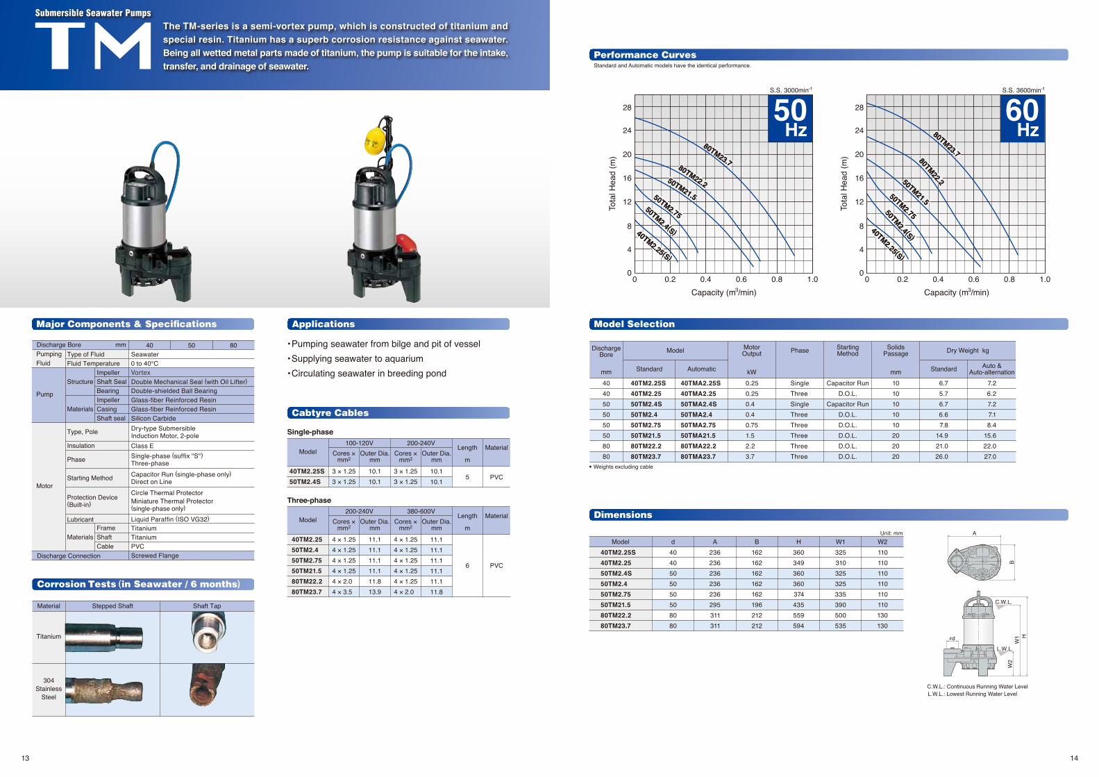
Model d A B H W1 W240TM2.25S 40TM2.25 50TM2.4S 50TM2.4 50TM2.75 50TM21.5 80TM22.2 80TM23.7
4040505050508080
236236236236236295311311
162162162162162196212212
360349360360374435559594
325310325325335390500535
110110110110110110130130
0.8 1.00.60.40.2 0.8 1.00.60.40.2
12
8
4
16
20
24
28
12
8
4
16
20
24
28
Capacity (m /min)3
S.S. 3000min-1
50Hz
C.W.L.: Continuous Running Water LevelL.W.L.: Lowest Running Water Level
d
A
B
L.W.L.
C.W.L.
W2
W1 H
40TM2.25(S)
40TM2.25(S)
50TM2.4(S)
50TM2.4(S)
50TM2.75
50TM2.75
50TM21.5
50TM21.5
80TM22.2
80TM22.2
80TM23.7
80TM23.7
60Hz
40TM2.25(S)
40TM2.25(S)
50TM2.4 (S )
50TM2.4 (S )50TM2.75
50TM2.75
50TM21.5
50TM21.5
80TM22.2
80TM22.2
80TM23.7
80TM23.7
Corrosion Tests (in Seawater / 6 months)
Applications
Performance Curves
• Pumping seawater from bilge and pit of vessel• Supplying seawater to aquarium• Circulating seawater in breeding pond
Major Components & Specifications
The TM-series is a semi-vortex pump, which is constructed of titanium and special resin. Titanium has a superb corrosion resistance against seawater. Being all wetted metal parts made of titanium, the pump is suitable for the intake, transfer, and drainage of seawater.
Submersible Seawater Pumps
Model Selection
Cabtyre Cables
Single-phase
Three-phase
• Weights excluding cable
Unit: mm
Dimensions
1413
Capacity (m /min)3
S.S. 3600min-1
0 0
Tota
l Hea
d (m
)
Tota
l Hea
d (m
)
0 0
Standard and Automatic models have the identical performance.
• Weights excluding cable
PumpingFluid
Discharge Connection
Pump
Discharge Bore 32mm
MotorMiniature Thermal Protector
Wastewater andWater carrying Small Solid Matters0 to 40℃VortexDouble Mechanical SealDouble-shielded Ball BearingGlass-fiber Reinforced ResinGlass-fiber Reinforced ResinSilicon CarbideDry-type SubmersibleInduction Motor, 2-poleClass ESingle-phaseCapacitor Run
Liquid Paraffin (ISO VG32)304 Stainless Steel420 Stainless SteelPVCScrewed Flange
DischargeBore
MotorOutput Phase Starting
MethodSolids
Passage Dry Weight kg Cabtyre CableModel
Standard Automatic Standard AutomaticMaterialLength100-240V
C.W.L.: Continuous Running Water LevelL.W.L.: Lowest Running Water Level
140
20370
280 31
6
C.W.L.
L.W.L.
32
50/60Hz
50Hz60HzMajor Components & Specifications
Applications
Performance Curves
Model Selection
Dimensions
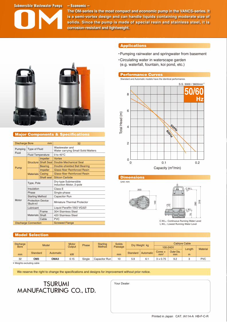
The OM-series is the most compact and economic pump in the VANCS-series. It is a semi-vortex design and can handle liquids containing moderate size of solids. Since the pump is made of special resin and stainless steel, it is corrosion-resistant and lightweight.
Submersible Wastewater Pumps --- Economic ---
• Pumping rainwater and springwater from basement• Circulating water in waterscape garden (e.g. waterfall, fountain, koi pond, etc.)
S.S. 3000 / 3600min-1
Standard and Automatic models have the identical performance.
Unit: mm
We reserve the right to change the specifications and designs for improvement without prior notice.