1 General ................................................................................................................................................... 6
1.6 Technical data ......................................................................................................................................... 8
1.7 Dimensions and weights ......................................................................................................................... 9
3 Transport and storage ........................................................................................................................ 10
3.1 Transport ............................................................................................................................................... 10
3.1.1 Standing transport ................................................................................................................................. 10
3.1.2 Transport in a horizontal manner .......................................................................................................... 11
3.2 Transport securing devices ................................................................................................................... 11
3.2.1 Motor connection cable moisture protection ......................................................................................... 11
3.2.2 Transport securing device for AFP submersible pump shafts ............................................................... 12
3.2.3 Transport security of pump and impeller for motors with an impeller installed ...................................... 14
3.2.4 Constructional assembly of the volute for motors with an impeller installed ......................................... 14
3.2.5 Transport securing device for submersible pump shafts AFL/VUP ....................................................... 15
3.3 Storage of the units ............................................................................................................................... 15
4.2.3 Temperature monitoring of the bearings. .............................................................................................. 18
4.2.4 Temperature indication .......................................................................................................................... 19
4.3 Operation with frequency inverters ....................................................................................................... 20
5.5.1 Standard connection diagrams, mains voltage 380 - 420 V at 50 Hz/460 V at 60 Hz. ......................... 29
5.5.2 Standard connection diagrams, mains voltage 400 V at 50 Hz/460 V at 60 Hz, M8/M9 motors ........... 30
5.5.3 Lead designations ................................................................................................................................ 30
5.5.4 Checking direction of rotation ................................................................................................................ 31
5.5.5 Changing direction of rotation .............................................................................................................. 31
5.5.6 Connection of the control circuit leads .................................................................................................. 32
5.5.7 Connection of the seal monitoring unit to the control panel .................................................................. 32
7.1 General maintenance hints ................................................................................................................... 34
7.2 Maintenance hints if the submersible pump is out of use for a considerable period ............................ 35
7.2.1 Before installation .................................................................................................................................. 35
7.2.2 After installation ..................................................................................................................................... 35
7.3 Removal of the submersible pump ....................................................................................................... 35
7.3.1 Removal of the AFP submersible pump from a wet sump .................................................................... 35
7.3.2 Removal of the AFP submersible pump when dry installed .................................................................. 35
7.3.3 Removal of the AFL and VUP submersible pump ................................................................................ 36
8 Assembling the gearbox AFL/VUP .................................................................................................... 36
8.1 Assembling the motor and the gearbox/hydraulic unit (M8) .................................................................. 36
8.2 Remove transport securing device (M8) .............................................................................................. 37
8.3 Remove transport securing device of the gearbox (M8) ....................................................................... 38
8.4 Assembly instructions for gearbox/motor housing (M8) ........................................................................ 39
8.5 Assembling the motor and the gearbox/hydraulic unit (M9) .................................................................. 40
8.6 Remove transport securing device (M9) ............................................................................................... 41
8.7 Remove transport securing device of the gearbox (M9) ...................................................................... 41
8.8 Assembly instructions for gearbox/motor housing (M9) ........................................................................ 42
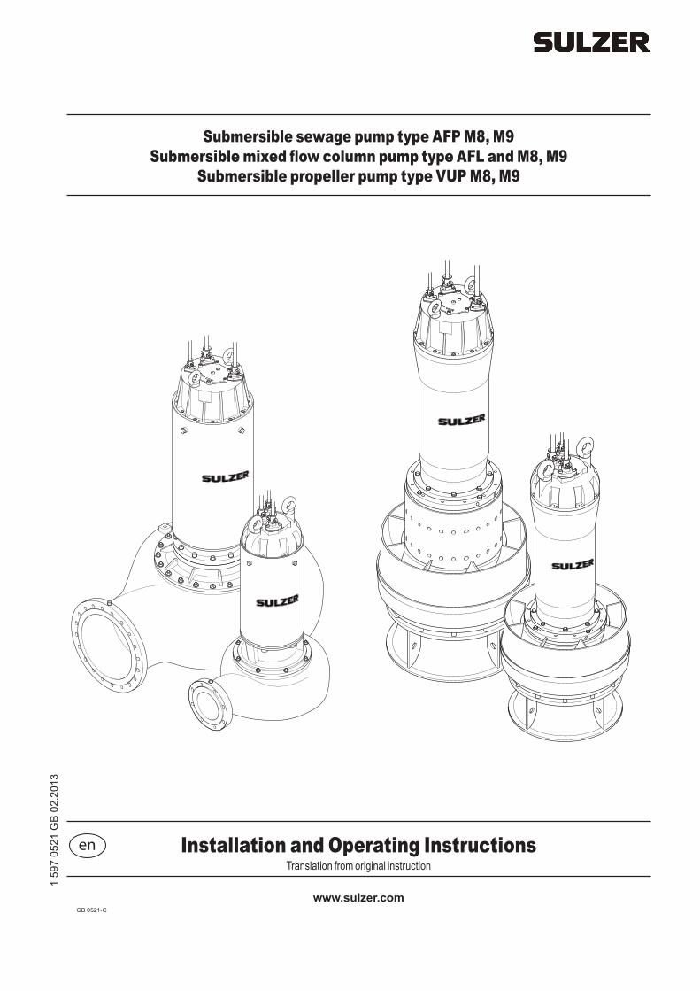
Installation and Operating Instructions
AFP M8, M9 | AFL M8, M9 | VUP M8, M9
GB 0521-C 5
Installation and Operating Instructions
AFP M8, M9 | AFL M8, M9 | VUP M8, M9
GB 0521-C6
1 General
1.1 IntroductionThese Installation and Operating Instructions and the separate booklet Safety Hints contain basic instructions and safety hints which must be observed during transport, installation and commissioning. For this reason it is essential that they are read by the installing technician as well as by relevant skilled operators or users. They should also be always available where the unit is installed.
m Safety Instructions which might cause danger to life in case of non-observance have been specifically highlighted with the general danger symbol.
c The presence of a dangerous voltage is identified with this safety symbol.
g This symbol indicates the danger of an explosion occurring.
ATTENTION Appears at safety hints, the non-observance of which could damage the unit or affect its functioning.
NOTE Used for important pieces of information.
Illustrations code; e.g. (3/2). The first digit refers to the figure no. and the second digit to the position in that figure.
1.2 Correct usage of the productsThe ABS products have been designed and built in accordance with the latest technology and taking into account the relevant safety regulations. However improper usage could cause a danger to life or limb of the user of a third party or cause damage or function impairment to the unit itself and other items of value.
The ABS units should only be used if they are in perfect technical condition taking into account all safety requirements and conscious of the need to avoid potentially dangers. The contents of the installation and operating instructions and the safety hints must be applied! Any other usage (abnormal usage) or usage beyond that specified will be considered as non-compliance.
The manufacturer/supplier will not accept any responsibility for damage due to this. The risk is borne by the user. In case of doubt the entire scope of the planned application must be approved by Sulzer Pump Solutions Germany ( in the following called Sulzer ).
In the case of any faults arising, the ABS units should immediately be taken out of use and secured. The fault should be immediately rectified or, if necessary, contact your ABS service centre.
1.3 Application restrictions of the submersible pumpsThe submersible pumps can be supplied both as standard versions and in explosion-proof execution with (ATEX II 2Gk EEx dII B T4) for 50 Hz or FM (NEC 500, Class I, Division 1, Group C&D, T3C) approval for 60 Hz
Limitations: Fluid temperature maximum 40 °C (104 °F)
Immersion depth maximum 20 m (65 ft)
ATTENTION If cable length is less than 20 m/65 ft the max. immersion depth reduces accordingly. In special cases an immersion depth greater than 20 m/65 ft is possible. In order to do this you need the written approval from the manufacturer Sulzer.
Installation and Operating Instructions
AFP M8, M9 | AFL M8, M9 | VUP M8, M9
GB 0521-C 7
g Pumping of flammable or explosive liquids with these pumps is not allowed!
g Only explosion-proof executions may be used in hazardous areas!
For the operation of units as explosion-proof execution the following applies:
In hazardous areas care must be taken that during switching on and operation of the pumps the pump section is filled with water (dry installation) or alternatively is submerged or under water (wet installation with cooling jacket. Other types of operation e.g. snore operation or dry running are not allowed!
ATTENTION The ex versions are not fitted with a seal monitor (DI) in the monitoring chamber or in the oil chamber. There is an option of an external seal monitor for the ex versions
For the operation of explosion-proof submersible pumps in wet-well installation without cooling jacket applies:
It must be ensured that the motor of the ex-submersible pump is always fully submerged during start-up and operation!
For the operation of explosion-proof submersible pumps applies:
The temperature monitoring of the explosion-proof submersible pumps has to be carried out by bimetallic temperature limiters or thermistors according to DIN 44 081-150 connected to a suitable release device which is certified in accordance with EC directive 94/9/EC.
For the operation of explosion-proof submersible pumps with frequency inverter applies:
Motors must have direct thermal protection devices fitted. These consist of temperature sensors (PTC DIN 44081-150) embedded in the windings. These must be connected to a suitable release device which is certified in accordance with EC directive 94/9/EC.
Machines designated as Ex machines may never, without exception, be operated using a mains frequency that is greater than the maximum of 50 or 60 Hz as indicated on the nameplate.
1.4 Application areas for the submersible pumps
1.4.1 Application areas for the series AFP
The ABS submersible sewage pumps of the AFP series have been designed for the economical and reliable pumping of commercial, industrial and municipal sewage and can be installed dry or wet.
They are suitable for pumping of the following liquids:
• Clear and wastewater, for sewage containing solids and fibrous material
• Faecal matter
• Sludge
• Fresh and process water pumping
• Raw water for drinking water supply
• Surface and rain water
• Sewage
In combination with the ABS automatic coupling system, the below ground level wet installation is a particularly economical and environmentally friendly solution. The pumps are also suitable for horizontal or vertical dry installation.
1.4.2 Application areas for the series AFL
The ABS mixed flow column pump of the AFL series have been developed for environmental protection, water supply, municipal sewage treatment and dewatering of polders.
Installation and Operating Instructions
AFP M8, M9 | AFL M8, M9 | VUP M8, M9
GB 0521-C8
They are suitable for the following liquids:
• Raw water with solid or fibrous material.
• Sewage
• Surface water, rain water, drainage water
• Sludge
The AFL pumps are installed in a concrete sump or in a steel pressure pipe using a suitable coupling ring
1.4.3 Application areas for the series VUP
ABS submersible propeller pumps of the VUP series are designed for those applications where large water volumes must be pumped at low heads (up to 10 m/33 ft).
They are suitable for the following liquids
• Fresh and process water pumping
• Raw water for drinking water supply
• Surface and rain water
Die VUP pumps are installed in a concrete sump or in a steel pressure pipe using a suitable coupling ring.
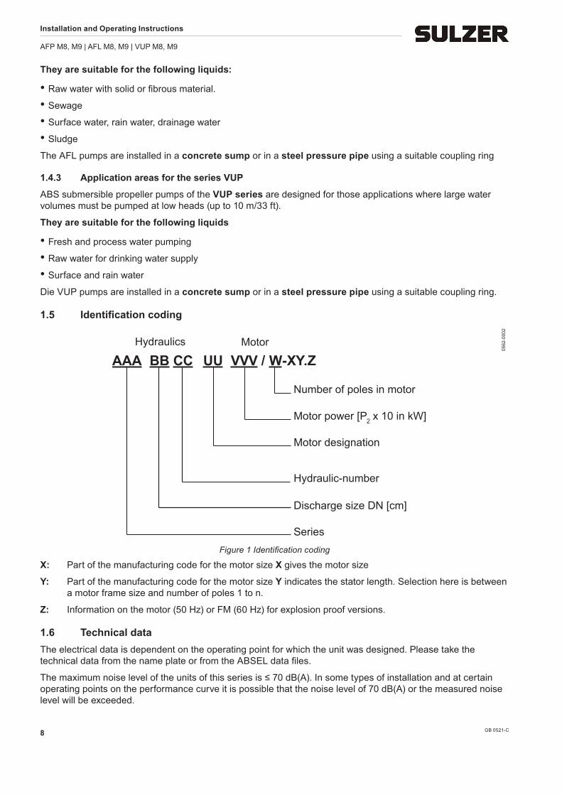
1.5 Identificationcoding
Series
Discharge size DN [cm]
Hydraulic-number
Motor
Number of poles in motor
Motor power [P2 x 10 in kW]
Motor designation (e.g. ME)
AAA BB CC UU VVV / W-XY.ZHydraulics
0562
-000
2
Figure 1 Identification coding
X: Part of the manufacturing code for the motor size X gives the motor size
Y: Part of the manufacturing code for the motor size Y indicates the stator length. Selection here is between a motor frame size and number of poles 1 to n.
Z: Information on the motor (50 Hz) or FM (60 Hz) for explosion proof versions.
1.6 Technical dataThe electrical data is dependent on the operating point for which the unit was designed. Please take the technical data from the name plate or from the ABSEL data files.
The maximum noise level of the units of this series is ≤ 70 dB(A). In some types of installation and at certain operating points on the performance curve it is possible that the noise level of 70 dB(A) or the measured noise level will be exceeded.
Installation and Operating Instructions
AFP M8, M9 | AFL M8, M9 | VUP M8, M9
GB 0521-C 9
1.7 Dimensions and weightsThe dimensions of the unit can be found on the relevant dimensional sheet. The hydraulic curves and impeller type can be found on the ABSEL hydraulics curve sheet. Please take the technical data and the weight of the units from the nameplate.
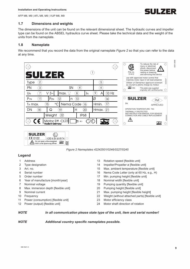
1.8 NameplateWe recommend that you record the data from the original nameplate Figure 2 so that you can refer to the data at any time.
IP68
Motor Eff. Cl.
1
Hmax.
Weight
SN
n
PN
Ø
DN
Hz
Nema Code
P 2N1N
Q
Hmin.
H
max.
Type
P
21
4 6
2
7
5
3
9IN A
15
14
1716
108
1211 13
201918
22
23
TA max. °C
UN V 3~
24
originally with certified pump
raising or lowering
use with approved motor control that
au courant a pleine charge du moteur
matches motor input in full load amperes
Utiliser un Demarreur approuve covenant
42
24
02
27
and servicing this device
To reduce the risk ofinjury or electricalshock, disconnectthe power before
This plate was supplied-SN:
File no.51412
APPROVED
FM
OPERATION TEMPERATURE: T3C
42
24
02
45
THERMALLY PROTECTEDSEE INSTRUCTION MANUAL FOR SENSORCONNECTION AND CABLE REPLACEMENT
SN:
0551
-000
8
Figure 2 Nameplates 42242501/0246/0227/0245
Legend 1 Address 13 Rotation speed [flexible unit] 2 Type designation 14 Impeller/Propeller ø [flexible unit] 3 Art. no. 15 Max. ambient temperature [flexible unit] 4 Serial number 16 Nema Code Letter (only at 60 Hz, e.g., H) 5 Order number 17 Min. pumping height [flexible unit] 6 Year of manufacture [month/year] 18 Nominal width [flexible unit] 7 Nominal voltage 19 Pumping quantity [flexible unit] 8 Max. immersion depth [flexible unit] 20 Pumping height [flexible unit] 9 Nominal current 21 Max. pumping height [flexible height] 10 Frequency 22 Weight (without attached parts) [flexible unit] 11 Power (consumption) [flexible unit] 23 Motor efficiency class 12 Power (output) [flexible unit] 24 Motor shaft direction of rotation
NOTE In all communication please state type of the unit, item and serial number!
NOTE Additional country specific nameplates possible.
Installation and Operating Instructions
AFP M8, M9 | AFL M8, M9 | VUP M8, M9
GB 0521-C10
2 SafetyThe general and specific health and safety hints are described in detail in the separate booklet Safety Hints. If anything is not clear or you have any questions as to safety make certain to contact the manufacturer Sulzer.
3 Transport and storage
3.1 Transport
c The unit must never be raised by the power cable.
Depending on model and mode of installation, the units are prepared at the factory for vertical or horizontal transportation.
Depending on the version, the units are fitted with eyes, eyebolts or attachment swivels (horizontal installation), to which a chain can be fastened by means of shackles to transportation, installation or removal.
m Take note of the entire weight of the unit (see nameplate Figure 2) The hoist and chain must be adequately dimensioned for the weight of the unit and must comply with the current valid safety regulations.
m The unit should be protected from rolling over!
m The unit is prepared for transportation by placing it on an adequately strong, completely horizontal sur-face taking care that it cannot topple over.
m Do not stay or work in the swivel area of a suspended load!
m The lifting hook height must take into consideration the entire height of the unit as well as the length of the lifting chain!
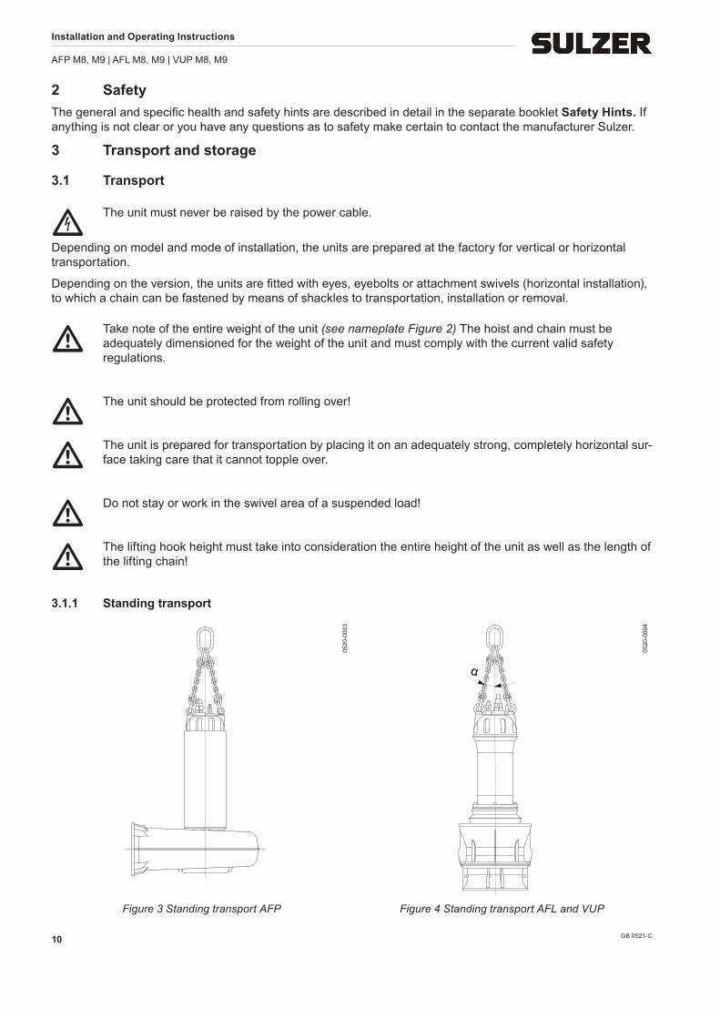
3.1.1 Standing transport
0520
-000
3
α
0520
-000
4
Figure 3 Standing transport AFP Figure 4 Standing transport AFL and VUP
Installation and Operating Instructions
AFP M8, M9 | AFL M8, M9 | VUP M8, M9
GB 0521-C 11
m The safety hints in the section above must be observed!
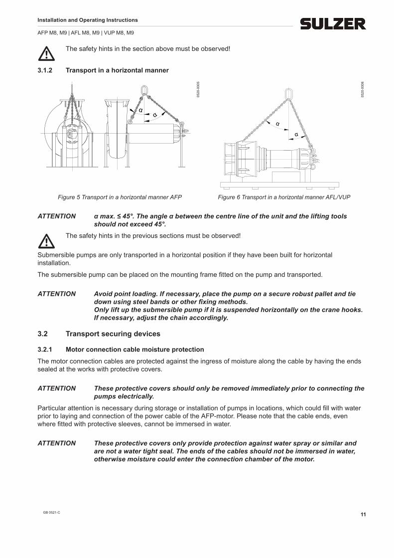
3.1.2 Transport in a horizontal manner
αα
0520
-000
5
α
1210
α
0520
-000
6
Figure 5 Transport in a horizontal manner AFP Figure 6 Transport in a horizontal manner AFL/VUP
ATTENTION α max. ≤ 45°. The angle α between the centre line of the unit and the lifting tools should not exceed 45°.
m The safety hints in the previous sections must be observed!
Submersible pumps are only transported in a horizontal position if they have been built for horizontal installation.
The submersible pump can be placed on the mounting frame fitted on the pump and transported.
ATTENTION Avoid point loading. If necessary, place the pump on a secure robust pallet and tie down using steel bands or other fixing methods. Only lift up the submersible pump if it is suspended horizontally on the crane hooks. If necessary, adjust the chain accordingly.
3.2 Transport securing devices
3.2.1 Motor connection cable moisture protection
The motor connection cables are protected against the ingress of moisture along the cable by having the ends sealed at the works with protective covers.
ATTENTION These protective covers should only be removed immediately prior to connecting the pumps electrically.
Particular attention is necessary during storage or installation of pumps in locations, which could fill with water prior to laying and connection of the power cable of the AFP-motor. Please note that the cable ends, even where fitted with protective sleeves, cannot be immersed in water.
ATTENTION These protective covers only provide protection against water spray or similar and are not a water tight seal. The ends of the cables should not be immersed in water, otherwise moisture could enter the connection chamber of the motor.
Installation and Operating Instructions
AFP M8, M9 | AFL M8, M9 | VUP M8, M9
GB 0521-C12
NOTE If there is a possibility of water ingress then the cables should be secured so that the ends are above the maximum possible flood level.
ATTENTION Take care not to damage the cable or its insulation when doing this!
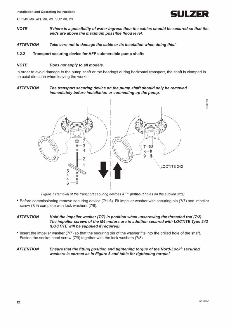
3.2.2 Transport securing device for AFP submersible pump shafts
NOTE Does not apply to all models.
In order to avoid damage to the pump shaft or the bearings during horizontal transport, the shaft is clamped in an axial direction when leaving the works.
ATTENTION The transport securing device on the pump shaft should only be removed immediately before installation or connecting up the pump.
789
LOCTITE 243
734
21
5446
0562
-000
8
Figure 7 Removal of the transport securing devices AFP (without holes on the suction side)
• Before commissioning remove securing device (7/1-6). Fit impeller washer with securing pin (7/7) and impeller screw (7/9) complete with lock washers (7/8).
ATTENTION Hold the impeller washer (7/7) in position when unscrewing the threaded rod (7/2). The impeller screws of the M4 motors are in addition secured with LOCTITE Type 243 (LOCTITE will be supplied if required).
• Insert the impeller washer (7/7) so that the securing pin of the washer fits into the drilled hole of the shaft. Fasten the socket head screw (7/9) together with the lock washers (7/8).
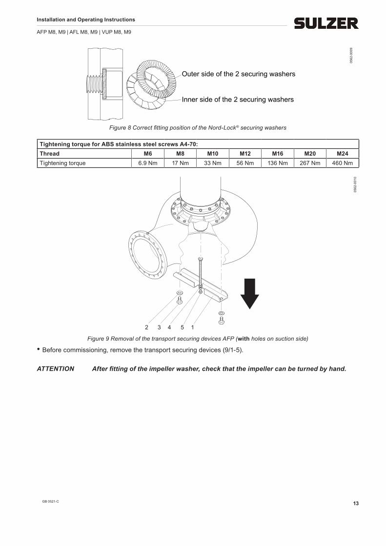
ATTENTION Ensure that the fitting position and tightening torque of the Nord-Lock® securing washers is correct as in Figure 8 and table for tightening torque!
Installation and Operating Instructions
AFP M8, M9 | AFL M8, M9 | VUP M8, M9
GB 0521-C 13
Outer side of the 2 securing washers
Inner side of the 2 securing washers
0562
-000
9
Figure 8 Correct fitting position of the Nord-Lock® securing washers
Figure 9 Removal of the transport securing devices AFP (with holes on suction side)
• Before commissioning, remove the transport securing devices (9/1-5).
ATTENTION After fitting of the impeller washer, check that the impeller can be turned by hand.
Installation and Operating Instructions
AFP M8, M9 | AFL M8, M9 | VUP M8, M9
GB 0521-C14
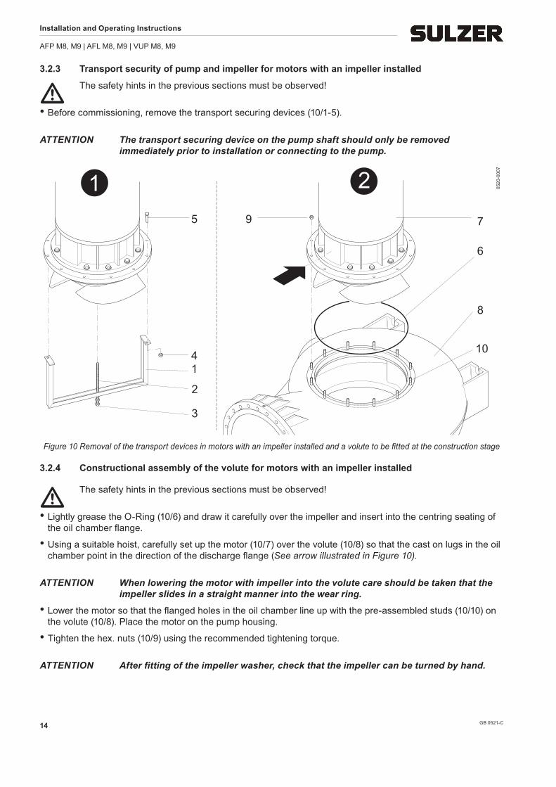
3.2.3 Transport security of pump and impeller for motors with an impeller installed
m The safety hints in the previous sections must be observed!
• Before commissioning, remove the transport securing devices (10/1-5).
ATTENTION The transport securing device on the pump shaft should only be removed immediately prior to installation or connecting to the pump.
1 2
3
1
2
4
5 79
6
8
10
0520
-000
7
Figure 10 Removal of the transport devices in motors with an impeller installed and a volute to be fitted at the construction stage
3.2.4 Constructional assembly of the volute for motors with an impeller installed
m The safety hints in the previous sections must be observed!
• Lightly grease the O-Ring (10/6) and draw it carefully over the impeller and insert into the centring seating of the oil chamber flange.
• Using a suitable hoist, carefully set up the motor (10/7) over the volute (10/8) so that the cast on lugs in the oil chamber point in the direction of the discharge flange (See arrow illustrated in Figure 10).
ATTENTION When lowering the motor with impeller into the volute care should be taken that the impeller slides in a straight manner into the wear ring.
• Lower the motor so that the flanged holes in the oil chamber line up with the pre-assembled studs (10/10) on the volute (10/8). Place the motor on the pump housing.
• Tighten the hex. nuts (10/9) using the recommended tightening torque.
ATTENTION After fitting of the impeller washer, check that the impeller can be turned by hand.
Installation and Operating Instructions
AFP M8, M9 | AFL M8, M9 | VUP M8, M9
GB 0521-C 15
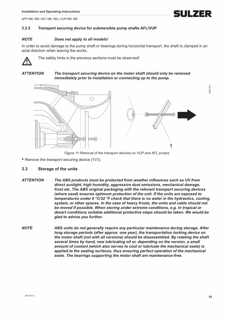
3.2.5 Transport securing device for submersible pump shafts AFL/VUP
NOTE Does not apply to all models!
In order to avoid damage to the pump shaft or bearings during horizontal transport, the shaft is clamped in an axial direction when leaving the works.
m The safety hints in the previous sections must be observed!
ATTENTION The transport securing device on the motor shaft should only be removed immediately prior to installation or connecting up to the pump.
1
0562
-001
1
Figure 11 Removal of the transport devices on VUP and AFL pumps
• Remove the transport securing device (11/1).
3.3 Storage of the units
ATTENTION The ABS products must be protected from weather influences such as UV from direct sunlight, high humidity, aggressive dust emissions, mechanical damage, frost etc. The ABS original packaging with the relevant transport securing devices (where used) ensures optimum protection of the unit. If the units are exposed to temperatures under 0 °C/32 °F check that there is no water in the hydraulics, cooling system, or other spaces. In the case of heavy frosts, the units and cable should not be moved if possible. When storing under extreme conditions, e.g. in tropical or desert conditions suitable additional protective steps should be taken. We would be glad to advise you further.
NOTE ABS units do not generally require any particular maintenance during storage. After long storage periods (after approx. one year), the transportation locking device on the motor shaft (not with all versions) should be disassembled. By rotating the shaft several times by hand, new lubricating oil or, depending on the version, a small amount of coolant (which also serves to cool or lubricate the mechanical seals) is applied to the sealing surfaces, thus ensuring perfect operation of the mechanical seals. The bearings supporting the motor shaft are maintenance-free.
Installation and Operating Instructions
AFP M8, M9 | AFL M8, M9 | VUP M8, M9
GB 0521-C16
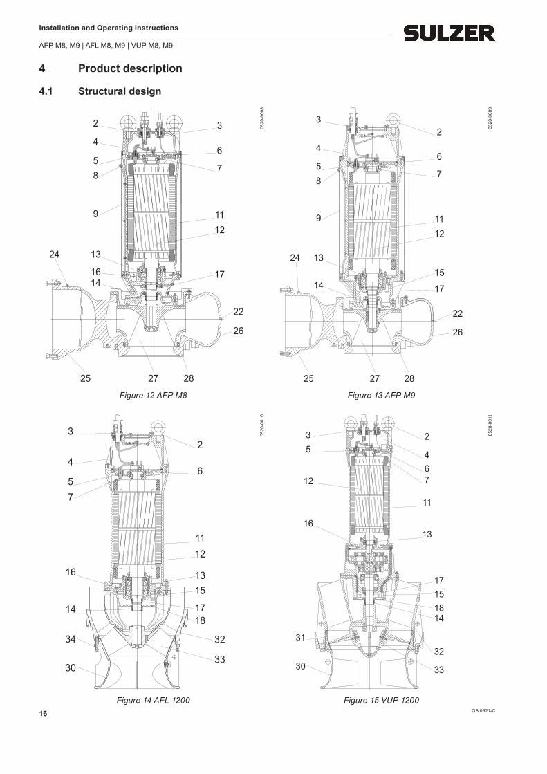
4 Product description
4.1 Structural design
7
6
3
1112
17
26
22
25 2827
2
1614
1324
9
85
4(((((( ((((((((
0520
-000
8
7
6
2
1112
17
26
22
15
25 2827
3
14
1324
9
85
4
0520
-000
9
Figure 12 AFP M8 Figure 13 AFP M9
6
2
1112
1718
33
32
1315
3
14
30
34
16
75
4
0520
-001
0
467
2
11
13
1815
33
32
17
14
5
31
30
16
12
3 0520
-001
1
Figure 14 AFL 1200 Figure 15 VUP 1200
Installation and Operating Instructions
AFP M8, M9 | AFL M8, M9 | VUP M8, M9
GB 0521-C 17
Legend 1 Lifting hoop (Standard) 18 Release screw 2 Eyebolts (Option) 19 Plug screw motor chamber 3 Cable inlet 20 Contrablock (CB) - impeller 4 Connection chamber 21 Contrablock (CB) - bottom plate 5 Cable gland 22 Release screw (horizontal dry- installation) 6 Seal monitoring (DI) connection chamber (option) 23 Adjusting screw for bottom plate 7 Temperature monitoring upper bearing (option) 24 Connection for pressure monitoring/venting 8 Filling - and venting screw 25 Discharge outlet 9 Cooling jacket 26 Volute 10 Cooling liquid 27 Impeller (closed multi channel version) 11 Stator 28 Wear ring in the volute 12 Rotor shaft 29 Wear ring on the impeller (option) 13 Temperature monitoring lower bearing (Option) 30 Bellmouth 14 Mechanical seal (medium side) 31 Wear ring (not for all versions) 15 Seal monitoring (DI) oil chamber 32 Guide ring 16 Seal monitoring (DI) motor chamber 33 Propeller VUP, impeller AFL 17 Mechanical seal (motor side) 34 Adjusting screw for gap between impeller and wall (AFL)
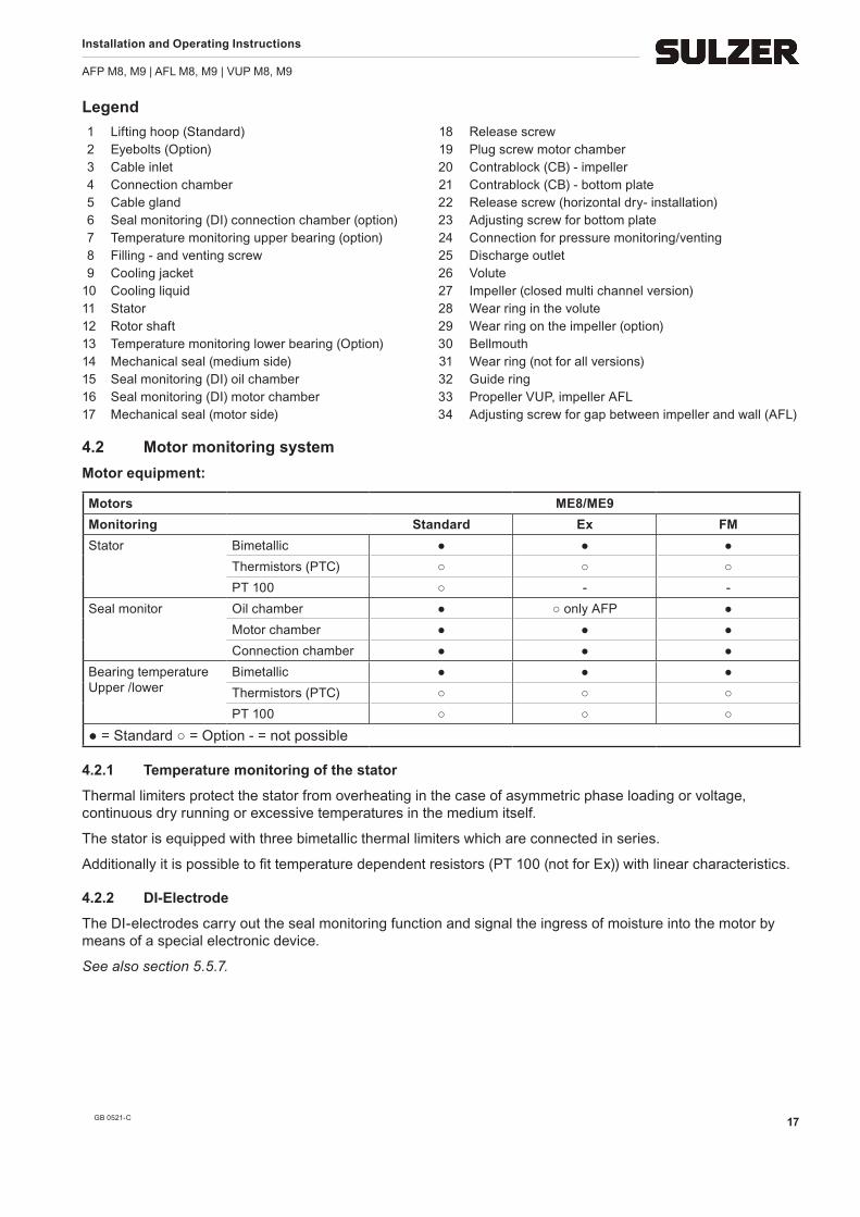
4.2 Motor monitoring systemMotor equipment:
Motors ME8/ME9Monitoring Standard Ex FMStator Bimetallic ● ● ●
Thermistors (PTC) ○ ○ ○PT 100 ○ - -
Seal monitor Oil chamber ● ○ only AFP ●Motor chamber ● ● ●Connection chamber ● ● ●
Thermal limiters protect the stator from overheating in the case of asymmetric phase loading or voltage, continuous dry running or excessive temperatures in the medium itself.
The stator is equipped with three bimetallic thermal limiters which are connected in series.
Additionally it is possible to fit temperature dependent resistors (PT 100 (not for Ex)) with linear characteristics.
4.2.2 DI-Electrode
The DI-electrodes carry out the seal monitoring function and signal the ingress of moisture into the motor by means of a special electronic device.
See also section 5.5.7.
Installation and Operating Instructions
AFP M8, M9 | AFL M8, M9 | VUP M8, M9
GB 0521-C18
ATTENTION Thermistors or PT 100 devices must never be directly connected into the control or power system. They must always be connected to a suitable evaluation device. Switch off temperature of the thermal sensors fitted to standard motors of Insulation Class F = 140° C/284° F. The temperature limiting switches may only be operated as specified by the manufacturer (See table below).
Operating voltage ...AC/...DC ...500 V ~/...101 V=
Rated voltage AC 250 V
Rated current AC cos φ = 1,0 2.5 A
Rated current AC cos φ = 0,6 1.6 A
max. switching current at IN 5.0 A
ATTENTION The maximum switching ability of the thermal sensors is 5 A, the rated voltage 250 V. Explosion-proof motors which are connected to static frequency inverters must be fitted with thermistors. Activation must be by means of a thermistor protective relay device with PTB-Approval number.
4.2.3 Temperature monitoring of the bearings.
If bearing temperature monitoring is supplied, the standard versions of the pump possess a bimetallic thermal limiter which opens at a pre-set temperature and is fitted into the bearing block. This allows switching off of the motor to take place in plenty of time, e.g. where excessive bearing temperature due to wear occurs.
Switching temperature of motors of insulation class F :
• Upper bearing = 140 °C/284 °F
• lower bearing = 120 °C/248 °F
As an alternative temperature dependent resistors (thermistors,/PTC) with non-linear characteristics or PT 100 elements with linear characteristics can be fitted.
Installation and Operating Instructions
AFP M8, M9 | AFL M8, M9 | VUP M8, M9
GB 0521-C 19
4.2.4 Temperature indication
A continuous indication of the temperature in the stator and the bearings is not possible using bimetallic thermal limiters or thermistors. For this application it is necessary to fit thermal sensors of the type PT 100 with linear characteristics into the stator and bearing blocks. This type of resistor has a linear characteristic, i.e. the resistance rise is proportional to the temperature rise.
Resistance
Temperature
0562
-001
7 Application Option
Function Temperature switch using the bimetallic principle, which opens at a rated temperature
Switching Taking care not to exceed the allowable switching current, these can be fitted directly into the control circuit
Figure 16 Curve showing principle of operation of bimetallic temperature limiter
Resistance
Temperature
0562
-001
8 Application Option
Function Temperature dependent resistance (no switch) curve with stepwise behaviour
Switching Cannot be installed direct into the control circuit. Evaluation of the signal must be carried out by suitable electronic equipment
Figure 17 Curve showing principle of operation of thermistor
Resistance
Temperature
0562
-001
9 Application Option (not for Ex)
Function Function temperature dependent resistance (no switch). The linear curve allows continuous measurement and indication of the temperature
Switching Cannot be installed direct into the control circuit. Evaluation of the signal must be carried out by suitable electronic equipment
Figure 18 Curve showing principle of operation of PT 100
Installation and Operating Instructions
AFP M8, M9 | AFL M8, M9 | VUP M8, M9
GB 0521-C20
4.3 Operation with frequency invertersThe stator design and the insulation grade of the motors from Sulzer means that they suitable for usage with fre-quency inverters. It is however essential that the following conditions are met when the motors are used with frequency inverters:
• The guidelines for EMC (electromagnetic compatibility) are complied with.
• Explosion-proof motors must be equipped with thermistors (PTC temperature sensors).
• Machines designated as Ex machines may never, without exception, be operated using a mains frequency that is greater than the maximum of 50 or 60 Hz as indicated on the type plate.
• Machines that are not designated as Ex machines may only be operated using the mains frequency indicated on the type plate. Greater frequencies can be used but only after consulting with and receiving permission from the Sulzer manufacturing plant.
• For operation of ex-motors on frequency inverters special requirements in relation to the tripping times of the thermo control elements, must be observed.
• The lowest frequency must be set so that the minimum fluid velocity of 1 m/s is present in the volute.
• The maximum frequency must be set so the rated power of the motor is not exceeded.
Modern frequency inverters are using higher wave frequencies and a steeper rise on the flanks of the voltage wave. This means that motors losses and motor noise is reduced. Unfortunately these inverter output signals cause higher voltage spikes in the stator. Experience has shown that, depending on rated voltage and the length of the cable between the inverter and the motor, these voltage spikes can adversely affect the life of the motor. In order to avoid this, inverters of this type must equipped with sinus filters when used in the critical zone (see Figure 19). The sinus filter chosen must be suitable for the inverter with regard to rated voltage, inverter wave frequency, rated current of the inverter and maximum inverter output frequency.
critical area
non critical area
L = total length (from frequency inverter to motor)
10 50 100 150 L[m]
UN[V]
660
600
460
400380
230
0562
-001
2
Figure 19 Critical/non critical area
Installation and Operating Instructions
AFP M8, M9 | AFL M8, M9 | VUP M8, M9
GB 0521-C 21
5 Installation
m The safety hints in the previous sections must be observed!
5.1 Installation of the AFP submersible pumps
5.1.1 Installation options for the AFP submersible pumpsThere are three main installation options for the submersible pumps:
1. Wet installation vertical with ABS automatic coupling system2. Dry installation with ground support ring (with cooling jacket)3. Dry installation horizontal (with cooling jacket)
NOTE The dimensional sheets and foundation plans for each type of installation are supplied either with the planning documents or your order confirmation.
5.2 Installation examples
17
16
18
14
11
324 65 71
16
15
12
910 8
13
0520
-001
2
Figure 20 Wet installation vertical with ABS automatic coupling system
Legend 1 Venting 10 Guide tube 2 Valve chamber 11 Discharge line 3 Shut-off valve 12 Inflow chamber with impact wall 4 Outflow line 13 Inflow line 5 Non-return valve 14 ABS submersible sewage pump 6 Fitting for valve removal 15 Automatic level control 7 Cable duct 16 Concrete benching 8 Bracket for float switches 17 Pedestal 9 Collection sump 18 Bracket
Installation and Operating Instructions
AFP M8, M9 | AFL M8, M9 | VUP M8, M9
GB 0521-C22
NOTE The pedestal and guide tube for the submersible pump must be fitted on site before installation of the pump. On request, we can send you detailed installation and foundation drawings. The specified concrete quality, min. B25 must be used.
19
14
18
6
11
5
3
4
9
21163
16
15
7 8 1
12
13
20
0520
-001
3
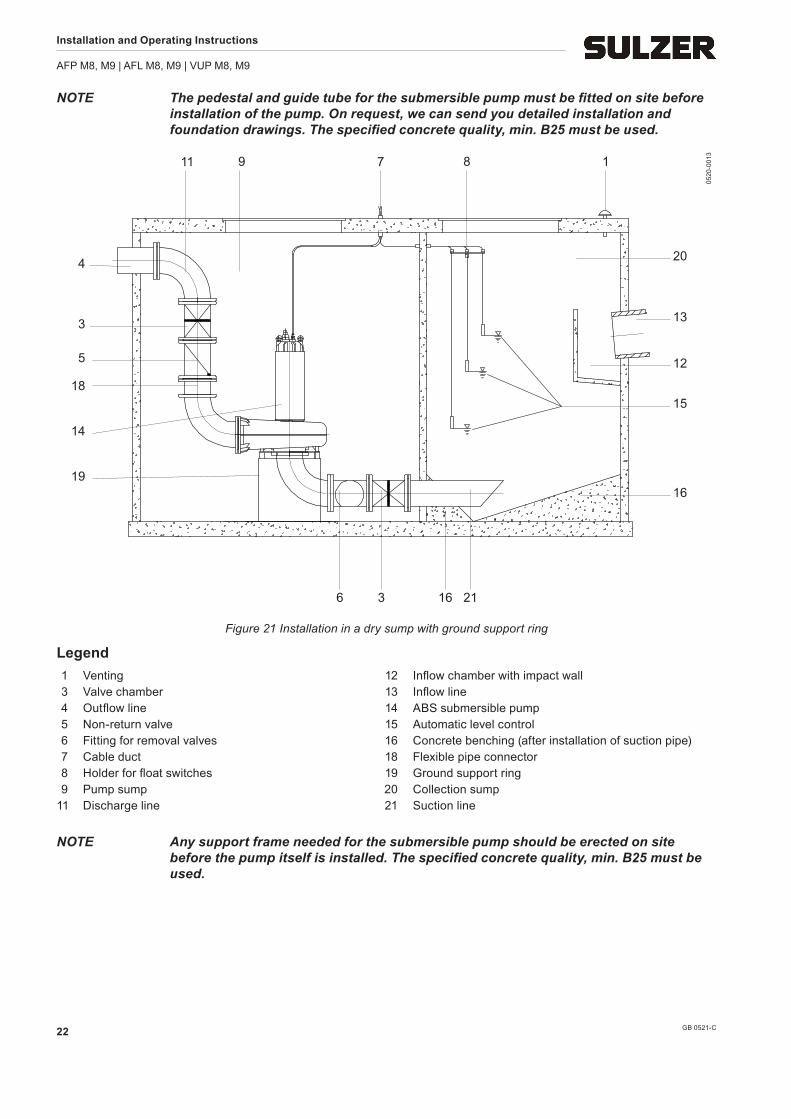
Figure 21 Installation in a dry sump with ground support ring
Legend 1 Venting 12 Inflow chamber with impact wall 3 Valve chamber 13 Inflow line 4 Outflow line 14 ABS submersible pump 5 Non-return valve 15 Automatic level control 6 Fitting for removal valves 16 Concrete benching (after installation of suction pipe) 7 Cable duct 18 Flexible pipe connector 8 Holder for float switches 19 Ground support ring 9 Pump sump 20 Collection sump 11 Discharge line 21 Suction line
NOTE Any support frame needed for the submersible pump should be erected on site before the pump itself is installed. The specified concrete quality, min. B25 must be used.
Installation and Operating Instructions
AFP M8, M9 | AFL M8, M9 | VUP M8, M9
GB 0521-C 23
5
14
23
24
25 6 3
3
4/119 7
12
16 21
16
15
8 1
13
20
0520
-001
4
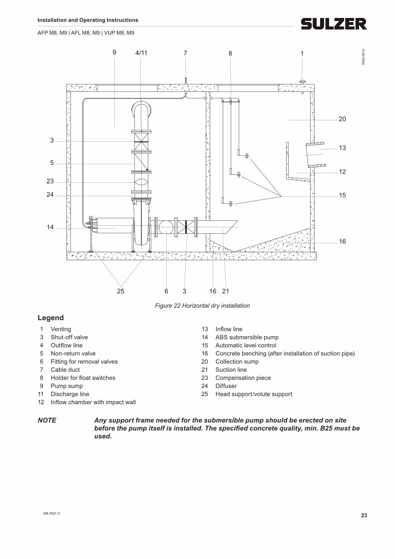
Figure 22 Horizontal dry installation
Legend 1 Venting 13 Inflow line 3 Shut-off valve 14 ABS submersible pump 4 Outflow line 15 Automatic level control 5 Non-return valve 16 Concrete benching (after installation of suction pipe) 6 Fitting for removal valves 20 Collection sump 7 Cable duct 21 Suction line 8 Holder for float switches 23 Compensation piece 9 Pump sump 24 Diffuser 11 Discharge line 25 Head support/volute support 12 Inflow chamber with impact wall
NOTE Any support frame needed for the submersible pump should be erected on site before the pump itself is installed. The specified concrete quality, min. B25 must be used.
Installation and Operating Instructions
AFP M8, M9 | AFL M8, M9 | VUP M8, M9
GB 0521-C24
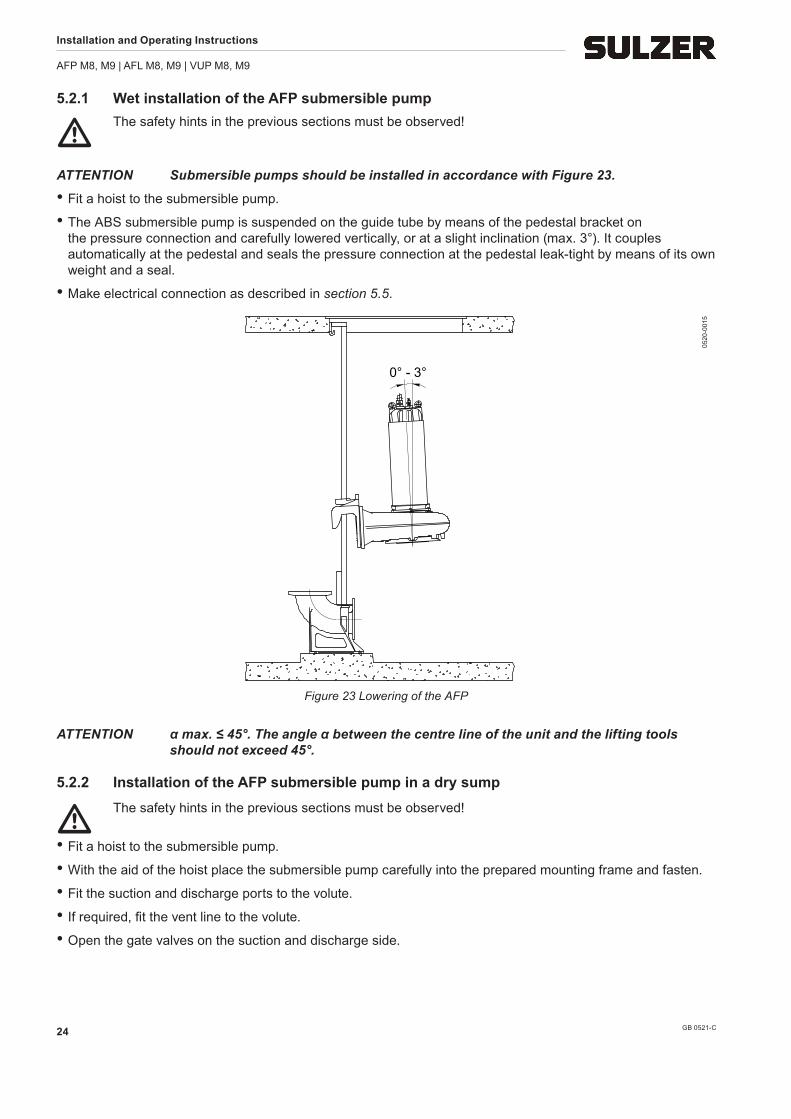
5.2.1 Wet installation of the AFP submersible pump
m The safety hints in the previous sections must be observed!
ATTENTION Submersible pumps should be installed in accordance with Figure 23.
• Fit a hoist to the submersible pump.
• The ABS submersible pump is suspended on the guide tube by means of the pedestal bracket on the pressure connection and carefully lowered vertically, or at a slight inclination (max. 3°). It couples automatically at the pedestal and seals the pressure connection at the pedestal leak-tight by means of its own weight and a seal.
• Make electrical connection as described in section 5.5.
0° - 3°
0520
-001
5Figure 23 Lowering of the AFP
ATTENTION α max. ≤ 45°. The angle α between the centre line of the unit and the lifting tools should not exceed 45°.
5.2.2 Installation of the AFP submersible pump in a dry sump
m The safety hints in the previous sections must be observed!
• Fit a hoist to the submersible pump.
• With the aid of the hoist place the submersible pump carefully into the prepared mounting frame and fasten.
• Fit the suction and discharge ports to the volute.
• If required, fit the vent line to the volute.
• Open the gate valves on the suction and discharge side.
Installation and Operating Instructions
AFP M8, M9 | AFL M8, M9 | VUP M8, M9
GB 0521-C 25
5.3 Fitting the pedestal
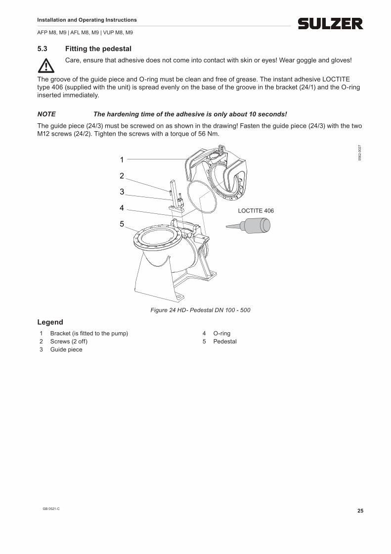
m Care, ensure that adhesive does not come into contact with skin or eyes! Wear goggle and gloves!
The groove of the guide piece and O-ring must be clean and free of grease. The instant adhesive LOCTITE type 406 (supplied with the unit) is spread evenly on the base of the groove in the bracket (24/1) and the O-ring inserted immediately.
NOTE The hardening time of the adhesive is only about 10 seconds!
The guide piece (24/3) must be screwed on as shown in the drawing! Fasten the guide piece (24/3) with the two M12 screws (24/2). Tighten the screws with a torque of 56 Nm.
1 2 3 4 5
LOCTITE 406
0562
-002
7
Figure 24 HD- Pedestal DN 100 - 500
Legend 1 Bracket (is fitted to the pump) 4 O-ring 2 Screws (2 off) 5 Pedestal 3 Guide piece
Installation and Operating Instructions
AFP M8, M9 | AFL M8, M9 | VUP M8, M9
GB 0521-C26
5.4 Installation of the AFL and VUP submersible pumps
m The safety hints in the previous sections must be observed!
5.4.1 Types of installation of the AFL and VUP submersible pumps
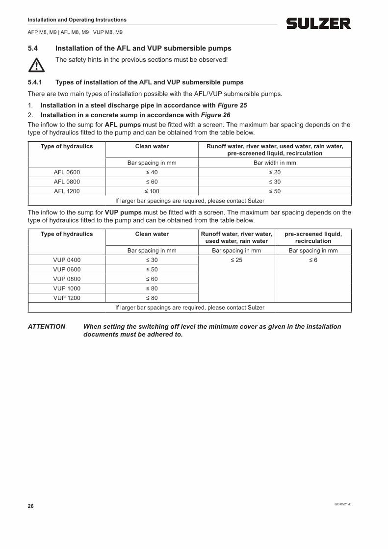
There are two main types of installation possible with the AFL/VUP submersible pumps.
1. Installation in a steel discharge pipe in accordance with Figure 252. Installation in a concrete sump in accordance with Figure 26The inflow to the sump for AFL pumps must be fitted with a screen. The maximum bar spacing depends on the type of hydraulics fitted to the pump and can be obtained from the table below.
Type of hydraulics Clean water Runoff water, river water, used water, rain water, pre-screened liquid, recirculation
Bar spacing in mm Bar width in mmAFL 0600 ≤ 40 ≤ 20AFL 0800 ≤ 60 ≤ 30AFL 1200 ≤ 100 ≤ 50
If larger bar spacings are required, please contact Sulzer
The inflow to the sump for VUP pumps must be fitted with a screen. The maximum bar spacing depends on the type of hydraulics fitted to the pump and can be obtained from the table below.
Type of hydraulics Clean water Runoff water, river water, used water, rain water
pre-screened liquid, recirculation
Bar spacing in mm Bar spacing in mm Bar spacing in mmVUP 0400 ≤ 30 ≤ 25 ≤ 6VUP 0600 ≤ 50VUP 0800 ≤ 60VUP 1000 ≤ 80VUP 1200 ≤ 80
If larger bar spacings are required, please contact Sulzer
ATTENTION When setting the switching off level the minimum cover as given in the installation documents must be adhered to.
Installation and Operating Instructions
AFP M8, M9 | AFL M8, M9 | VUP M8, M9
GB 0521-C 27
5.4.2 Installations examples with AFL and VUP submersible pumps
1 87
2
4
6
5
10 12
0520
-001
6
187
5
4
6
3
10 12
0520
-001
7
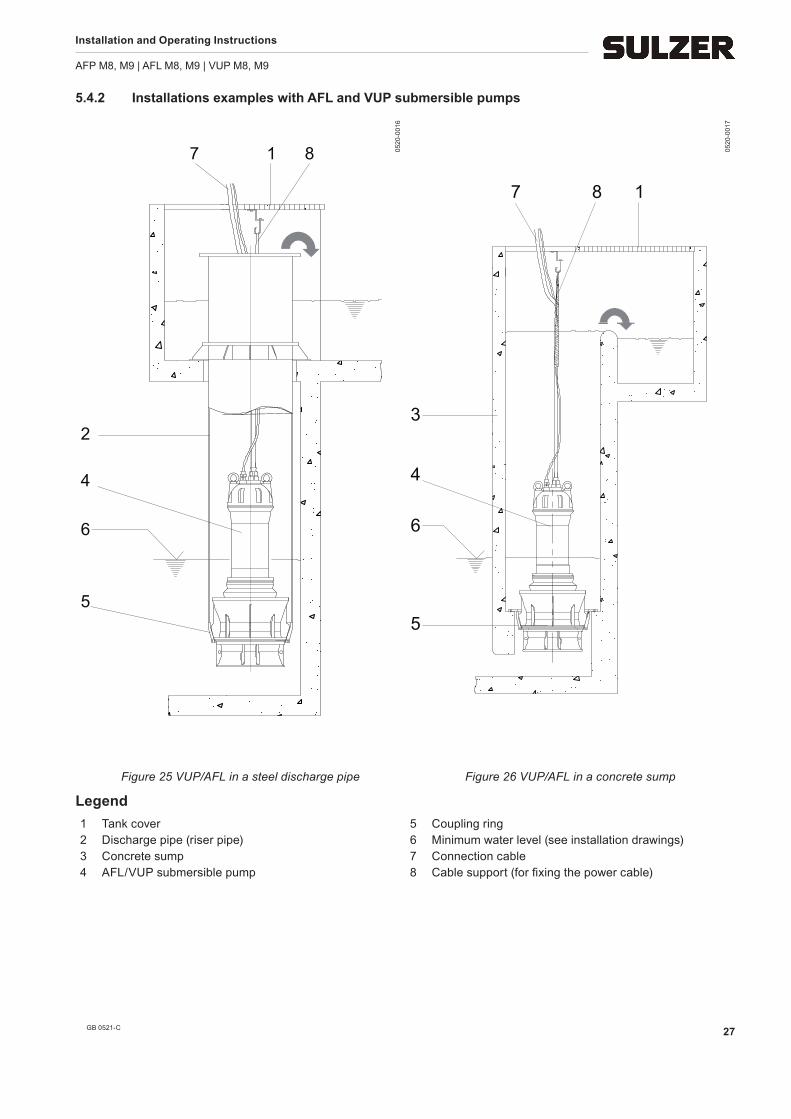
Figure 25 VUP/AFL in a steel discharge pipe Figure 26 VUP/AFL in a concrete sump
Legend 1 Tank cover 5 Coupling ring 2 Discharge pipe (riser pipe) 6 Minimum water level (see installation drawings) 3 Concrete sump 7 Connection cable 4 AFL/VUP submersible pump 8 Cable support (for fixing the power cable)
Installation and Operating Instructions
AFP M8, M9 | AFL M8, M9 | VUP M8, M9
GB 0521-C28
5.4.3 Installation of the AFL and VUP submersible pumps
m The safety hints in the previous sections must be observed!
ATTENTION The power cables should be handled carefully during installation and removal of the pumps in order to avoid damage to the insulation.
The coupling ring required for installation of the AFL/VUP submersible pump must already be installed as shown in Figure 25 and 26. Before installation of the pump a suitable support (hook) for the chain, as well as an opening and suspension (cable sock) for the cable must be provided in the sump or riser pipe.
NOTE In the case of AFL/VUP submersible pumps with gearbox the submersible motor and hydraulics mounted to the gearbox are supplied separately.
Before or during the installation the motor connection cables should be fitted on site with suitable strain relief (e.g. cable socks). Particular care should be taken that the cable insulation is not crushed or damaged by the weight of the hanging cable especially in the area of the cable inlet.
ATTENTION When raising the submersible pump out of the concrete sump or the steel discharge pipe with the hoist ensure that the connection cables are lifted out simultaneously as the pump itself is being raised.
5.4.4 Lowering of the AFL and VUP submersible pump into the coupling ring
ATTENTION Before lowering the pump a direction of rotation check should be carried out, see section 5.5.4.
• Draw the cable hose over the end of the connection cable.
ATTENTION The steel riser pipe, or concrete sump must be cleaned thoroughly (builder‘s rubble, etc.). Before fitting the pump into a sump or into a steel discharge pipe, care should be taken that any paint remnants are completely removed from the conical surfaces on the pumps or on the coupling ring. These conical surfaces must then be greased. To optimise the inflow and to reduce the noise level it is important that one pair of fins of the suction pipe are in line with the main flow direction of the inflow chamber. This must be observed when fitting the pump into a sump or into a steel discharge pipe.
• Carefully lower the submersible pump with the aid of a hoist into the coupling ring in the sump. Take care that the cable is lowered simultaneously and cannot snag.
• Attach the lifting chain to the hook provided so that it cannot strike either the pump cable or the sump wall.
• Tension the pump cable and fasten to the hook provided with the aid of the cable sock. Where a steel pressure pipe is used the connection cable should be brought through the connection cable inlet and sealed off in a watertight manner.
c The connection cable should only be tightened sufficiently so that no tension acts at the cable inlet in the head of the pump. The connection cable should not strike the chain or the sump wall.
• If necessary, the steel riser pipe is sealed off in a watertight manner.
Installation and Operating Instructions
AFP M8, M9 | AFL M8, M9 | VUP M8, M9
GB 0521-C 29
5.5 Electrical connection
m The safety hints in the previous sections must be observed!
Before commissioning an expert should check that one of the necessary electrical protective devices is avail-able. Earthing, neutral, earth leakage circuit breakers, etc. must comply with the regulations of the local electric-ity supply authority and a qualified person should check that these are in perfect order.
ATTENTION The power supply system on site must comply with VDE or other local regulations with regard to cross-sectional area and maximum voltage drop. The voltage stated on the nameplate of the pump must correspond to that of the mains.
c The incoming power supply as well as the connection of the pump itself to the terminals on the control panel must comply with the circuit diagram of the control panel as well as the motor connection diagrams and must be carried out by a qualified person.
The power supply cable must be protected by an adequately dimensioned slow-blow fuse corresponding to the rated power of the pump.
ATTTENTION The unit should only be operated with the overload relay and thermal sensors/limiters connected.
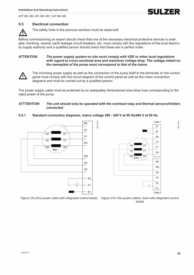
5.5.1 Standard connection diagrams, mains voltage 380 - 420 V at 50 Hz/460 V at 60 Hz.
M3 ~
PE
F1
DI
W2
V2
W1
V1
U2 U1
F0
V2
U2
W2
W1
U1
V1
0551
-003
2
M3 ~
Cable 2
Cable 1
W2
U2
V2
W1
V1
U1
F0
F1
U2
V2
W2
W1
PE
V1
U1
Di
Di
PE
0551
-003
3
Figure 27a (One power cable with integrated control leads) Figure 27b (Two power cables, each with integrated control leads)
Installation and Operating Instructions
AFP M8, M9 | AFL M8, M9 | VUP M8, M9
GB 0521-C30
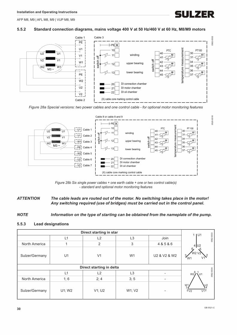
5.5.2 Standard connection diagrams, mains voltage 400 V at 50 Hz/460 V at 60 Hz, M8/M9 motors
M3 ~W2 W1
V2
U2
V1
U1
Cable 2
Cable 1
W2
V2
U2
PE
V1
W1
U1
PE
DI connection chamber20
(X) cable core marking control cable
2221 DI motor chamber
DI oil chamber
switc
h of
f
13
12
11
10
PE
winding
switc
h of
f 41
lower bearing
upper bearing
45
43
44
42
Cable 3
40
tem
pera
ture
mea
sure
men
t
31
ϑ
ϑ
ϑ
37ϑ
35
36ϑ
34ϑ
PTC PT10030
X 0562
-003
2
Figure 28a Special versions: two power cables and one control cable - for optional motor monitoring features
W2 W1
V2
U2
V1
U1Cable 1U1
DI connection chamber20
(X) cable core marking control cable
2221 DI motor chamber
DI oil chamber
switc
h of
f
13
12
11
10
PE
switc
h of
f 41
lower bearing
upper bearing
45
43
44
42
winding
Cable 8 or cable 8 and 9
40
tem
pera
ture
mea
sure
men
t
31
ϑ
ϑ
ϑ
37ϑ
35
36ϑ
34ϑ
PTC PT 10030
X
M3 ~
Cable 2V1
Cable 3W1
Cable 4PE
Cable 5W2
Cable 6U2
Cable 7V2
0520
-001
8
Figure 28b Six single power cables + one earth cable + one or two control cable(s) - standard and optional motor monitoring features
ATTENTION The cable leads are routed out of the motor. No switching takes place in the motor! Any switching required (use of bridges) must be carried out in the control panel.
NOTE Information on the type of starting can be obtained from the nameplate of the pump.
5.5.3 Lead designations
Direct starting in star1 U1
46
3 2
5U2
W2 V2W1 V1
0562
-003
3
L1 L2 L3 JoinNorth America 1 2 3 4 & 5 & 6
Sulzer/Germany U1 V1 W1 U2 & V2 & W2
Direct starting in delta1
U1
4
6
325
U2
W2
V2
W1
V1
0562
-003
4
L1 L2 L3 -North America 1; 6 2; 4 3; 5 -
Sulzer/Germany U1; W2 V1; U2 W1; V2 -
Installation and Operating Instructions
AFP M8, M9 | AFL M8, M9 | VUP M8, M9
GB 0521-C 31
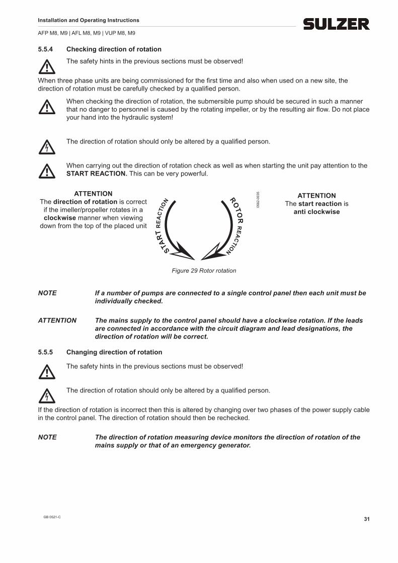
5.5.4 Checking direction of rotation
m The safety hints in the previous sections must be observed!
When three phase units are being commissioned for the first time and also when used on a new site, the direction of rotation must be carefully checked by a qualified person.
m When checking the direction of rotation, the submersible pump should be secured in such a manner that no danger to personnel is caused by the rotating impeller, or by the resulting air flow. Do not place your hand into the hydraulic system!
c The direction of rotation should only be altered by a qualified person.
m When carrying out the direction of rotation check as well as when starting the unit pay attention to the START REACTION. This can be very powerful.
STAR
T R
EA
CTI
ON RO
TOR
RE
AC
TION
0562
-003
5 ATTENTION The start reaction is
anti clockwise
Figure 29 Rotor rotation
NOTE If a number of pumps are connected to a single control panel then each unit must be individually checked.
ATTENTION The mains supply to the control panel should have a clockwise rotation. If the leads are connected in accordance with the circuit diagram and lead designations, the direction of rotation will be correct.
5.5.5 Changing direction of rotation
m The safety hints in the previous sections must be observed!
c The direction of rotation should only be altered by a qualified person.
If the direction of rotation is incorrect then this is altered by changing over two phases of the power supply cable in the control panel. The direction of rotation should then be rechecked.
NOTE The direction of rotation measuring device monitors the direction of rotation of the mains supply or that of an emergency generator.
ATTENTION The direction of rotation is correct
if the imeller/propeller rotates in a clockwise manner when viewing
down from the top of the placed unit
Installation and Operating Instructions
AFP M8, M9 | AFL M8, M9 | VUP M8, M9
GB 0521-C32
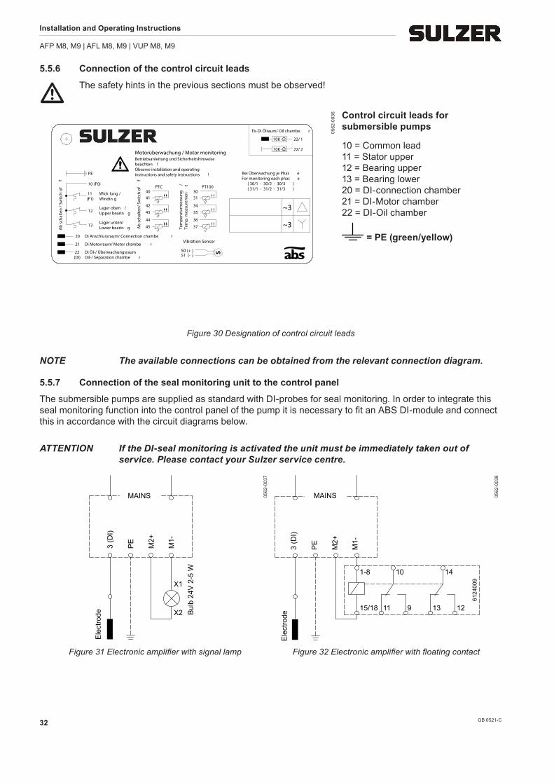
5.5.6 Connection of the control circuit leads
m The safety hints in the previous sections must be observed!
Ab
scha
lten/
Sw
itch
off
45
44
43
42
4140
PTC
Tem
pera
turm
essu
ng/
Tem
p. m
easu
rem
ent
37
36
35
34
3130
PT100
22(DI)
21
Di Öl-/ ÜberwachungsraumOil-/ Separation chambe r
Di Motorraum/ Motor chambe r
Di Anschlussraum/ Connection chambe r20
22/ 2
22/ 1
10K -
10K -
Vibration Sensor
50 (+ )51 (- )
~3
~3Lager unten/Lower bearin g
Lager oben /Upper bearin g
Wick lung /Windin g
PE
13
12
11(F1)
10 (F0)
Ab
scha
lten
/ Sw
itch
off
Betriebsanleitung und Sicherheitshinweise
Observe installation and operating
Motorüberwachung / Motor monitoring
( 31/1 - 31/2 - 31/3 )
beachten !
instructions and safety instructions !
Ex-Di Ölraum/ Oil chambe r
Bei Überwachung je Phas eFor monitoring each phas e
NOTE The available connections can be obtained from the relevant connection diagram.
5.5.7 Connection of the seal monitoring unit to the control panel
The submersible pumps are supplied as standard with DI-probes for seal monitoring. In order to integrate this seal monitoring function into the control panel of the pump it is necessary to fit an ABS DI-module and connect this in accordance with the circuit diagrams below.
ATTENTION If the DI-seal monitoring is activated the unit must be immediately taken out of service. Please contact your Sulzer service centre.
X1
X2
Ele
ctro
de3
(DI)
PE
M2+
M1-
Bul
b 24
V 2
-5 W
MAINS 0562
-003
7
Ele
ctro
de3
(DI)
PE
6124
009
M2+
M1-
MAINS
1-8
15/18
10
11 9 13 12
14
0562
-003
8
Figure 31 Electronic amplifier with signal lamp Figure 32 Electronic amplifier with floating contact
Installation and Operating Instructions
AFP M8, M9 | AFL M8, M9 | VUP M8, M9
GB 0521-C 33
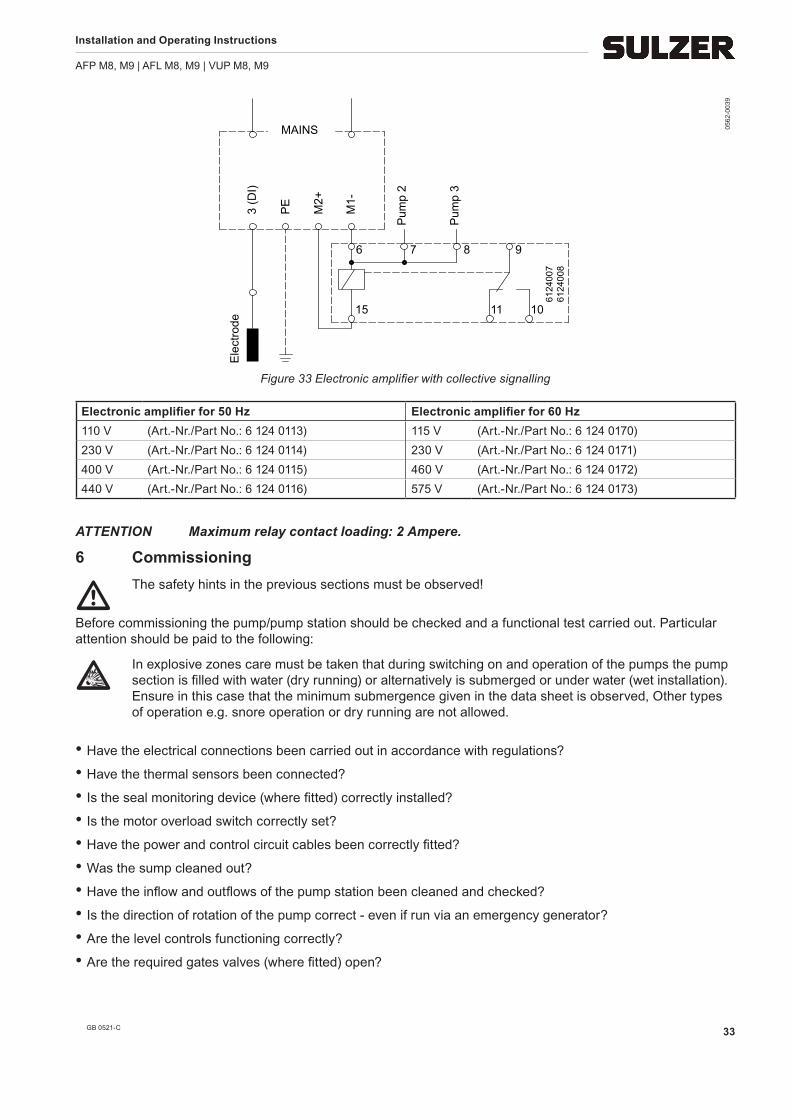
Ele
ctro
de3
(DI)
PE
6124
007
6124
008
M2+
M1-
MAINS
6
15 11 10
7 8 9
Pum
p 2
Pum
p 3
0562
-003
9
Figure 33 Electronic amplifier with collective signalling
Electronicamplifierfor50Hz Electronicamplifierfor60Hz110 V (Art.-Nr./Part No.: 6 124 0113) 115 V (Art.-Nr./Part No.: 6 124 0170)230 V (Art.-Nr./Part No.: 6 124 0114) 230 V (Art.-Nr./Part No.: 6 124 0171)400 V (Art.-Nr./Part No.: 6 124 0115) 460 V (Art.-Nr./Part No.: 6 124 0172)440 V (Art.-Nr./Part No.: 6 124 0116) 575 V (Art.-Nr./Part No.: 6 124 0173)
ATTENTION Maximum relay contact loading: 2 Ampere.
6 Commissioning
m The safety hints in the previous sections must be observed!
Before commissioning the pump/pump station should be checked and a functional test carried out. Particular attention should be paid to the following:
g In explosive zones care must be taken that during switching on and operation of the pumps the pump section is filled with water (dry running) or alternatively is submerged or under water (wet installation). Ensure in this case that the minimum submergence given in the data sheet is observed, Other types of operation e.g. snore operation or dry running are not allowed.
• Have the electrical connections been carried out in accordance with regulations?
• Have the thermal sensors been connected?
• Is the seal monitoring device (where fitted) correctly installed?
• Is the motor overload switch correctly set?
• Have the power and control circuit cables been correctly fitted?
• Was the sump cleaned out?
• Have the inflow and outflows of the pump station been cleaned and checked?
• Is the direction of rotation of the pump correct - even if run via an emergency generator?
• Are the level controls functioning correctly?
• Are the required gates valves (where fitted) open?
Installation and Operating Instructions
AFP M8, M9 | AFL M8, M9 | VUP M8, M9
GB 0521-C34
AFP
• Do the non-return valves (where fitted) function easily?
• Have the hydraulics been vented in the case of dry installed pumps?
AFL/VUP
• Have the steel riser pipe, or concrete sump be cleaned thoroughly (builder’s rubble, etc.)
• Are any paint remnants are removed from the conical surfaces on the pumps or on the coupling ring? Are these conical surfaces be greased?
6.1 Starting frequency of the motorsThe allowable starting frequency per hour can be read from the table below (where not otherwise specified from the works).
Motor power maximum starts per hour at interval in minutes≤ 10 kW 20 3
11 - 160 kW 15 4> 160 kW 10 6
ATTENTION The allowable starting frequency for any starting devices should be obtained from manufacturer of these devices.
7 Maintenance
m The safety hints in the previous sections must be observed!
7.1 General maintenance hints
c Before commencing any maintenance work the pump should be completely disconnected from the mains by a qualified person and care should be taken that it cannot be inadvertently switched back on.
NOTE The maintenance hints given here are not designed for „do-it-yourself“ repairs as special technical knowledge is required.
g Repair work on explosion-proof motors may only be carried out in approved workshops by approved personnel using original parts supplied by the manufacturer. Otherwise the ex-approvals no longer apply.
ABS submersible pumps are reliable quality products each being subjected to careful final inspection. Lubri-cated-for-life ball bearings together with monitoring devices ensure optimum pump reliability provided that the pump has been connected and operated in accordance with the operating instructions.
Should, nevertheless, a malfunction occur, do not improvise but ask your Sulzer customer service department for assistance.
This applies particularly if the pump is continually switched off by the current overload in the control panel, by the thermal sensors/limiters of the thermo-control system or by the seal monitoring system (DI).
ATTENTION The lifting tools like chains and shackles should be visually checked in regular intervals (approx. every 3-month) for wear and corrosion. These parts should be replaced if required!
The Sulzer service organisation would be pleased to advise you on any applications you may have and to assist you in solving your pumping problems.
Installation and Operating Instructions
AFP M8, M9 | AFL M8, M9 | VUP M8, M9
GB 0521-C 35
NOTE The Sulzer warranty conditions are only valid provided that any repair work has been carried out in Sulzer approved workshops and where original ABS spare parts have been used.
7.2 Maintenance hints if the submersible pump is out of use for a considerable period
NOTE If the pumps have remained idle for more than 12 months then we recommend that you ask Sulzer or an approved distributor for advice.
7.2.1 Before installation
The covers giving moisture protection of the cables (see section 3.2.1) should be only removed immediately before actual installation of the pump. After the removal of the transport securing devices and before connecting up the pump electrically the motor shaft should be rotated a number of times by turning the impeller or propeller by hand.
7.2.2 After installation
If, after installation of the submersible pump, it remains out of use for prolonged periods (for example in storm water holding tanks) then we recommend that the pump be run for a maximum of 1 minute every 3 months in order to check both its functioning and availability.
g Attention: Dry running of Ex units located in areas where an explosion could occur Is not allowed!
7.3 Removal of the submersible pump
m The safety hints in the previous sections must be observed!
7.3.1 Removal of the AFP submersible pump from a wet sump
c Before removal of the unit the motor connection cables at the control panel should be completely disconnected by a qualified person from mains and care should be taken that it cannot be inadvertently switched back on.
g Before removal of units in hazardous areas the sump and surrounding area must be adequately vented to avoid the danger of a spark causing an explosion!
• Fit a hoist to the pump in accordance to section 3.1.
• Raise the submersible pump out of the sump with the hoist. While doing this the connection cables should be simultaneously drawn out of the sump as the pump itself is being raised.
• Place the pump with volute vertically on a solid surface and take care that it cannot fall over.
7.3.2 Removal of the AFP submersible pump when dry installed
• Close off the gate valves on the inlet and discharge sides.
• Empty the volute and, if necessary, the discharge line.
• If fitted, dismantle the venting line above the discharge.
• Install lifting gear, see 3.1 on the submersible pump.
• Disconnect the suction inlet by opening the bolts on the bottom plate of the hydraulics.
• Dismantle the discharge line by opening the bolts on the discharge flange of the volute.
• If necessary, remove the fastening bolts at the ground support ring and carefully lift off the pump with the hoist.
• Place the pump on an even, firm, flat surface.
Installation and Operating Instructions
AFP M8, M9 | AFL M8, M9 | VUP M8, M9
GB 0521-C36
7.3.3 Removal of the AFL and VUP submersible pump
• If present, the discharge pipe cover should be removed and the water pressure-tight cable inlet opened.
• Raise the submersible pump out of the concrete sump or the steel discharge pipe with the hoist. While doing this the connection cables should be drawn out as the pump itself is being raised.
• Place the submersible pump with propeller housing vertically on a solid surface, taking care that it cannot tip over.
8 Assembling the gearbox AFL/VUP
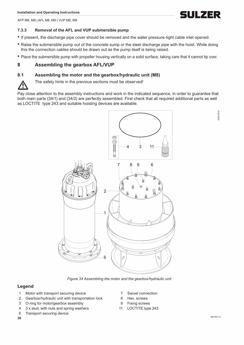
8.1 Assembling the motor and the gearbox/hydraulic unit (M8)
m The safety hints in the previous sections must be observed!
Pay close attention to the assembly instructions and work in the indicated sequence, in order to guarantee that both main parts (34/1) and (34/2) are perfectly assembled. First check that all required additional parts as well as LOCTITE type 243 and suitable hoisting devices are available.
1
2
7 8 9 6
3 114
6
0520
-001
9
Figure 34 Assembling the motor and the gearbox/hydraulic unit
Legend 1 Motor with transport securing device 7 Swivel connection 2 Gearbox/hydraulic unit with transportation lock 8 Hex. screws 3 O-ring for motor/gearbox assembly 9 Fixing screws 4 3 x stud, with nuts and spring washers 11 LOCTITE type 243 6 Transport securing device
Installation and Operating Instructions
AFP M8, M9 | AFL M8, M9 | VUP M8, M9
GB 0521-C 37
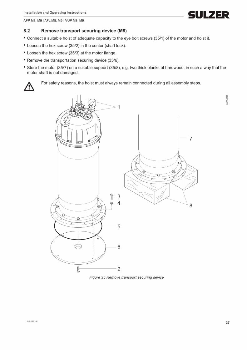
8.2 Remove transport securing device (M8) • Connect a suitable hoist of adequate capacity to the eye bolt screws (35/1) of the motor and hoist it.
• Loosen the hex screw (35/2) in the center (shaft lock).
• Loosen the hex screw (35/3) at the motor flange.
• Remove the transportation securing device (35/6).
• Store the motor (35/7) on a suitable support (35/8), e.g. two thick planks of hardwood, in such a way that the motor shaft is not damaged.
m For safety reasons, the hoist must always remain connected during all assembly steps.
34
5
6
2
7
8
1
0520
-002
0
Figure 35 Remove transport securing device
Installation and Operating Instructions
AFP M8, M9 | AFL M8, M9 | VUP M8, M9
GB 0521-C38
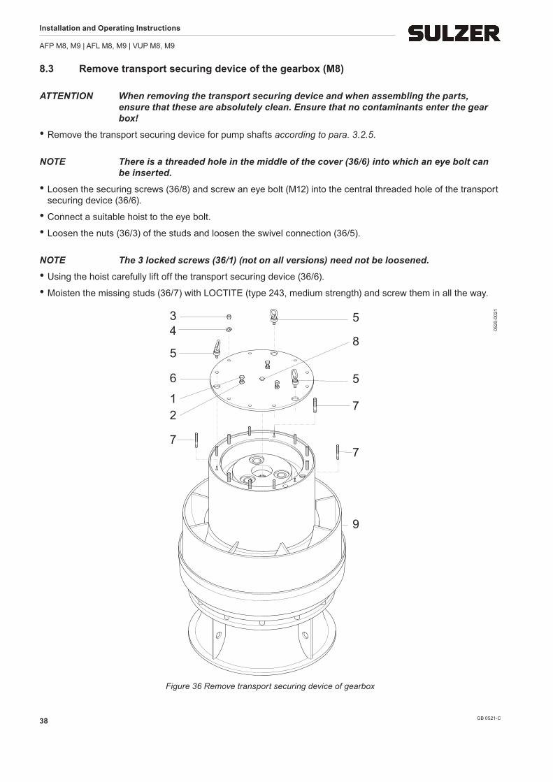
8.3 Remove transport securing device of the gearbox (M8)
ATTENTION When removing the transport securing device and when assembling the parts, ensure that these are absolutely clean. Ensure that no contaminants enter the gear box!
• Remove the transport securing device for pump shafts according to para. 3.2.5.
NOTE There is a threaded hole in the middle of the cover (36/6) into which an eye bolt can be inserted.
• Loosen the securing screws (36/8) and screw an eye bolt (M12) into the central threaded hole of the transport securing device (36/6).
• Connect a suitable hoist to the eye bolt.
• Loosen the nuts (36/3) of the studs and loosen the swivel connection (36/5).
NOTE The 3 locked screws (36/1) (not on all versions) need not be loosened.
• Using the hoist carefully lift off the transport securing device (36/6).
• Moisten the missing studs (36/7) with LOCTITE (type 243, medium strength) and screw them in all the way.
34
5
6
7
12
5
7
7
9
5
8
0520
-002
1
Figure 36 Remove transport securing device of gearbox
Installation and Operating Instructions
AFP M8, M9 | AFL M8, M9 | VUP M8, M9
GB 0521-C 39
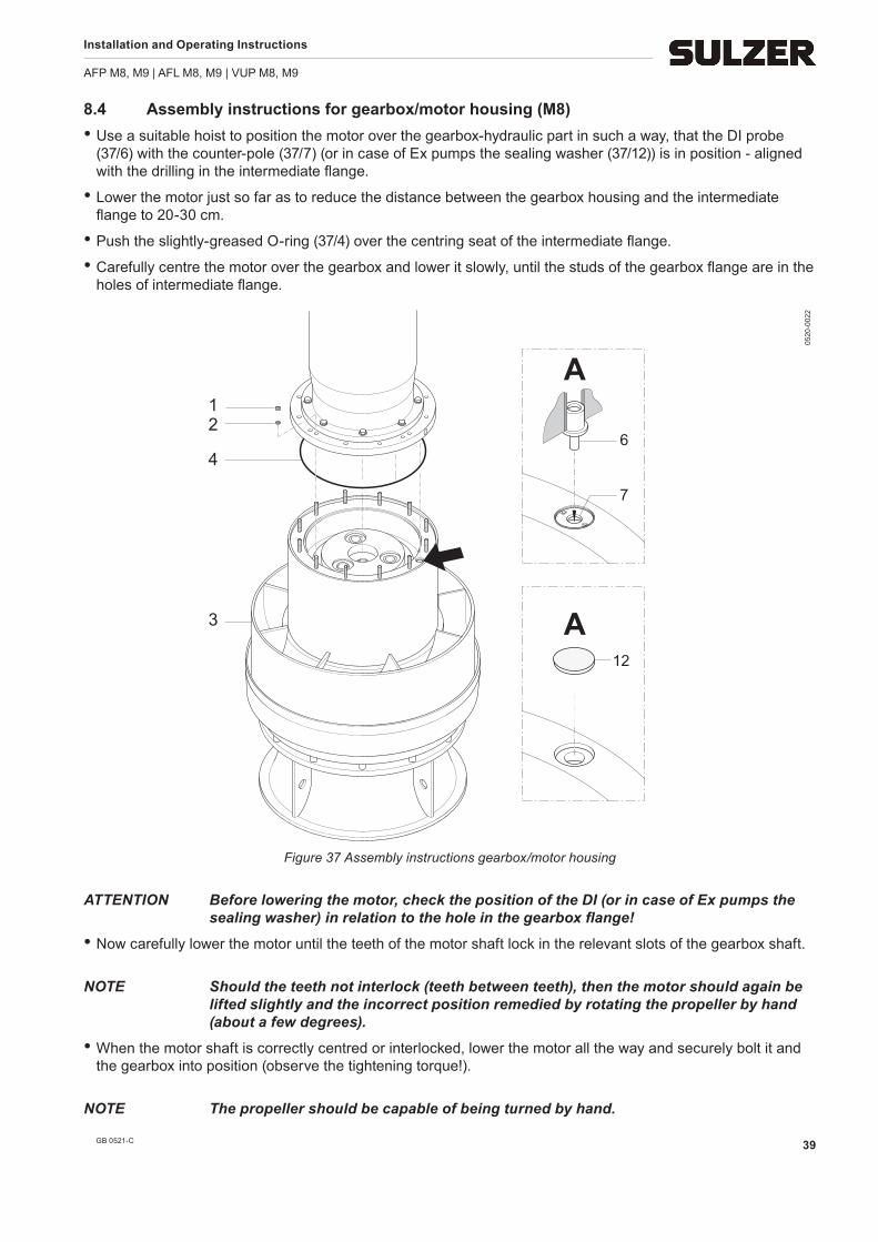
8.4 Assembly instructions for gearbox/motor housing (M8)• Use a suitable hoist to position the motor over the gearbox-hydraulic part in such a way, that the DI probe
(37/6) with the counter-pole (37/7) (or in case of Ex pumps the sealing washer (37/12)) is in position - aligned with the drilling in the intermediate flange.
• Lower the motor just so far as to reduce the distance between the gearbox housing and the intermediate flange to 20-30 cm.
• Push the slightly-greased O-ring (37/4) over the centring seat of the intermediate flange.
• Carefully centre the motor over the gearbox and lower it slowly, until the studs of the gearbox flange are in the holes of intermediate flange.
ATTENTION Before lowering the motor, check the position of the DI (or in case of Ex pumps the sealing washer) in relation to the hole in the gearbox flange!
• Now carefully lower the motor until the teeth of the motor shaft lock in the relevant slots of the gearbox shaft.
NOTE Should the teeth not interlock (teeth between teeth), then the motor should again be lifted slightly and the incorrect position remedied by rotating the propeller by hand (about a few degrees).
• When the motor shaft is correctly centred or interlocked, lower the motor all the way and securely bolt it and the gearbox into position (observe the tightening torque!).
NOTE The propeller should be capable of being turned by hand.
Installation and Operating Instructions
AFP M8, M9 | AFL M8, M9 | VUP M8, M9
GB 0521-C40
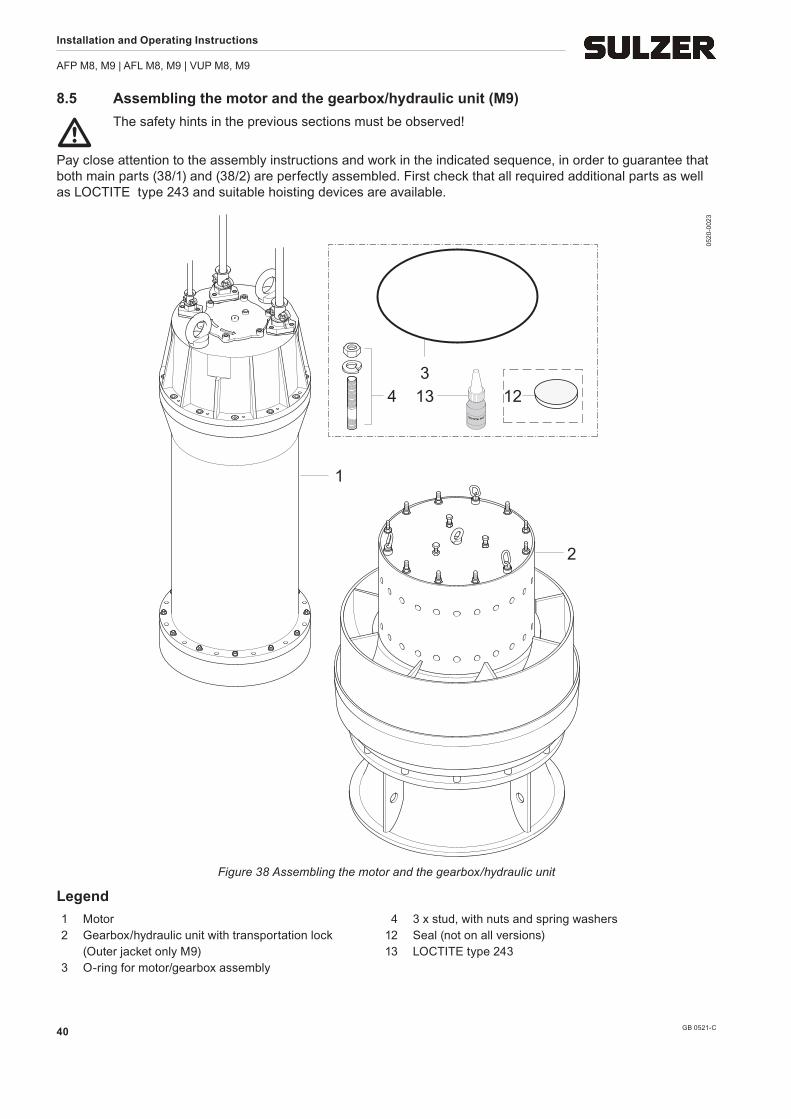
8.5 Assembling the motor and the gearbox/hydraulic unit (M9)
m The safety hints in the previous sections must be observed!
Pay close attention to the assembly instructions and work in the indicated sequence, in order to guarantee that both main parts (38/1) and (38/2) are perfectly assembled. First check that all required additional parts as well as LOCTITE type 243 and suitable hoisting devices are available.
13
1
2
43
12
0520
-002
3
Figure 38 Assembling the motor and the gearbox/hydraulic unit
Legend 1 Motor 4 3 x stud, with nuts and spring washers 2 Gearbox/hydraulic unit with transportation lock 12 Seal (not on all versions) (Outer jacket only M9) 13 LOCTITE type 243 3 O-ring for motor/gearbox assembly
Installation and Operating Instructions
AFP M8, M9 | AFL M8, M9 | VUP M8, M9
GB 0521-C 41
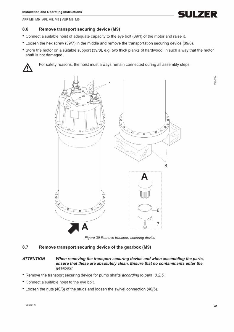
8.6 Remove transport securing device (M9)• Connect a suitable hoist of adequate capacity to the eye bolt (39/1) of the motor and raise it.
• Loosen the hex screw (39/7) in the middle and remove the transportation securing device (39/6).
• Store the motor on a suitable support (39/8), e.g. two thick planks of hardwood, in such a way that the motor shaft is not damaged.
m For safety reasons, the hoist must always remain connected during all assembly steps.
1
6
A
A 7
8
0520
-002
4
Figure 39 Remove transport securing device
8.7 Remove transport securing device of the gearbox (M9)
ATTENTION When removing the transport securing device and when assembling the parts, ensure that these are absolutely clean. Ensure that no contaminants enter the gearbox!
• Remove the transport securing device for pump shafts according to para. 3.2.5.
• Connect a suitable hoist to the eye bolt.
• Loosen the nuts (40/3) of the studs and loosen the swivel connection (40/5).
Installation and Operating Instructions
AFP M8, M9 | AFL M8, M9 | VUP M8, M9
GB 0521-C42
NOTE The 3 locked screws (40/1) need not be loosened.
• Carefully lift off the transport securing device (40/6) using the hoist.
• Moisten the missing studs (40/7) with LOCTITE (type 243, medium strength) and screw them in all the way.
1
2
34
56
77
7
0520
-002
5
Figure 40 Remove transport securing device of the gearbox
8.8 Assembly instructions for gearbox/motor housing (M9)• Use a suitable hoist to position the motor over the gearbox-hydraulic part in such a way, that the cam with the
DI probe (41/6) with the counter-pole (41/7) (or in case of Ex pumps the sealing washer (41/12)) is in position - aligned with the cam in the intermediate flange.
• Lower the motor just so far as to reduce the distance between the gearbox housing and the intermediate flange to 50 cm.
• Push the slightly-greased O-ring (41/4) over the centring seat of the intermediate flange.
• Carefully centre the motor over the gearbox and lower it slowly, until the studs of the gearbox flange are in the holes of intermediate flange.
ATTENTION Before lowering the motor, check the position of the DI (or in case of Ex pumps the sealing washer) in relation to the hole in the gearbox flange!
• Now carefully lower the motor until the teeth of the motor shaft lock in the relevant slots of the gearbox shaft.
NOTE Should the teeth not interlock (teeth between teeth), then the motor should again be lifted slightly and the incorrect position remedied by rotating the propeller by hand (about a few degrees).
Installation and Operating Instructions
AFP M8, M9 | AFL M8, M9 | VUP M8, M9
GB 0521-C 43
• When the motor shaft is correctly centred or interlocked, lower the motor all the way and securely bolt it and the gearbox into position (observe the tightening torque!).
NOTE The propeller should be capable of being turned by hand.
1
23
8
46
7A
A
12
A
0520
-002
6Figure 41 Assembly instructions for gearbox/motor housing
• Fasten the outer jacket (42/1) with the six fixing clamps (42/2) and the six M10 screws for these (42/3).
1 2 3
0520
-002
7
Figure 42 Fixing of the outer jacket
I Sulzer Pump Solutions Germany GmbH I Scheiderhöher Straße 30-38, D-53797 Lohmar, Germany I I Tel. +49 22 46 900 0 I Fax +49 22 46 900 200 I www.sulzer.com I