NOTE! To the installer: Please make sure you provide this manual to the owner of the equip ment or to the responsible party who maintains the system.
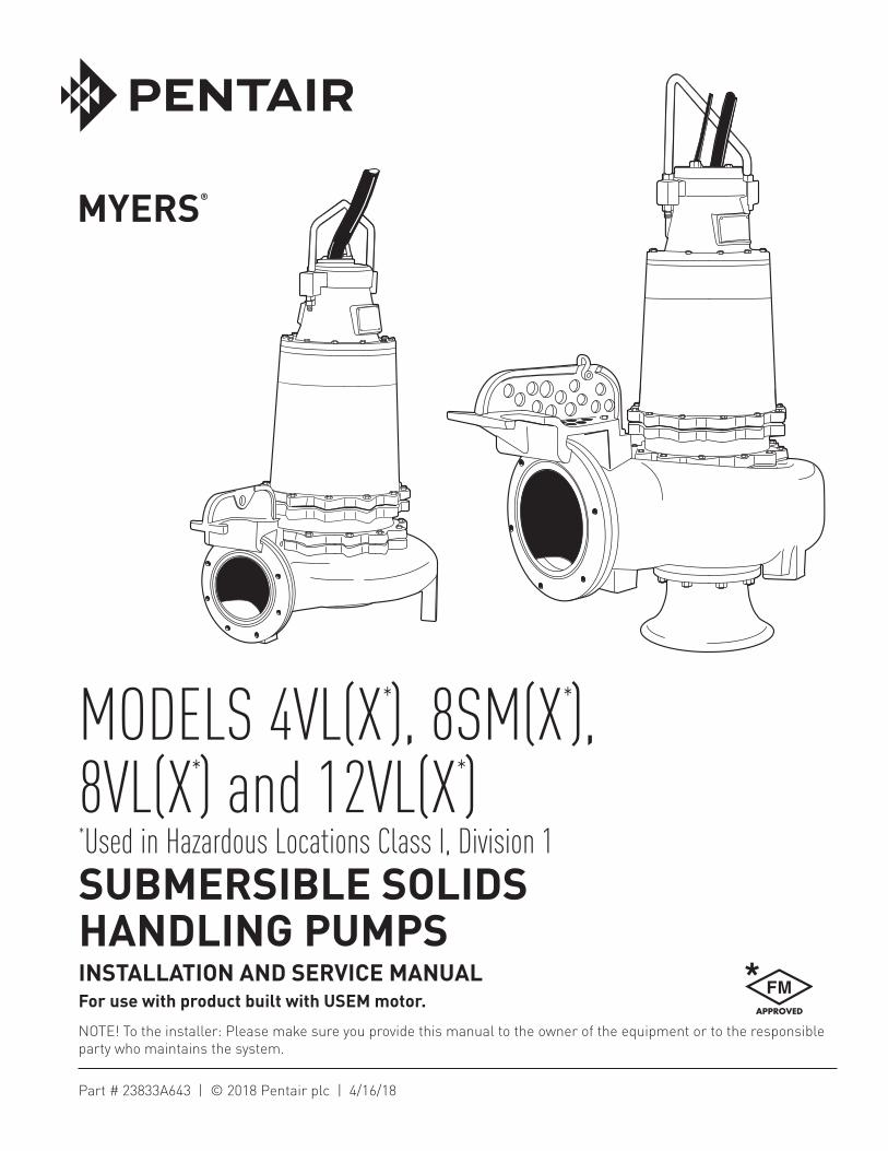
MODELS 4VL(X*), 8SM(X*), 8VL(X*) and 12VL(X*)*Used in Hazardous Locations Class I, Division 1SUBMERSIBLE SOLIDS HANDLING PUMPSINSTALLATION AND SERVICE MANUALFor use with product built with USEM motor.
CAUTION!Read these safety warnings first before installing, servicing, or operating any pump.
CALIFORNIA PROPOSITION 65 WARNING:
This product and related accessories contain chemicals known to the State of California to cause cancer, birth defects or other reproductive harm.
GENERAL 1. Most accidents can be avoided by using
COMMON SENSE. 2. Read the operation and maintenance instruction
manual supplied with the pump.
3. Do not wear loose clothing that can become entangled in the impeller or other moving parts.
4. This pump is designed to handle materials that could cause illness or disease through direct exposure. Wear adequate protective clothing when working on the pump or piping.
ELECTRICALWARNING: Only qualified persons shall conduct services and installations of this pump. The pump must be wired by a qualified electrician, using an approved starter box and switching device.
5. To reduce the risk of electrical shock, pump must be properly grounded in accordance with the National Electric Code and all applicable state and local ordinances.
6. To reduce risk of electrical shock, disconnect the pump from the power source before handling or servicing.
7. Any wiring to be done on pumps should be done by a qualified electrician.
8. Never operate a pump with a power cord that has frayed or brittle insulation.
9. Never let cords or plugs lie in water.
10. Never handle connected power cords with wet hands.
PUMPS 11. Pump builds up heat and pressure during
operation. Allow time for pump to cool before handling or servicing.
12. Only qualified personnel should install, operate or repair pump.
13. Keep clear of suction and discharge openings. DO NOT insert fingers in pump with power
connected.
14. Do not pump hazardous material not recommended for pump (flammable, caustic, etc.).
15. Make sure lifting handles are securely fastened each time before lifting.
16. Do not lift pump by power cord.
17. Do not exceed manufacturer’s recommendation for maximum performance, as this could cause the motor to overheat.
18. Secure the pump in its operating position so it cannot tip over, fall or slide.
19. Keep hands and feet away from impeller when power is connected.
20. Submersible solids handling pumps are not approved for use in swimming pools, recreational water installations, decorative fountains or any installation where human contact with the pumped fluid is common.
21. Do not operate pump without safety devices in place.
IMPORTANT! Myers® is not responsible for losses, injury or death resulting from a failure to observe these safety precautions, misuse or abuse of pumps or equipment.
GENERAL INFORMATION:Pump Models: These instructions cover the installation and service of the Myers 4VL, 4VLX, 8VL, 8VLX, 8SM, 8SMX, 12VL, and 12VLX series solids handling submersible pumps. The 4VLX, 8VLX, 8SMX and 12VLX models are Factory Mutual approved and listed hazardous location for hazardous sewage locations Class I, Division 1.
Motor HP and Voltages: These solids handling pumps are offered in three phase wiring configuration only. Voltages and speeds will vary according to the application and can be seen in the tables in this manual.
Electrical Controls: All of these pump models must be used with a control panel. Myers built control panels are designed to supply the correct electrical controls, motor starting equipment and include the circuitry for moisture and heat sensors. It is recommended that a Myers built control panel is used so that all warranties apply.
General Construction: The 4VLX, 8VLX, 8SMX and 12VLX motor construction is designed to meet Factory Mutual requirements for Class I, Division 1, sewage applications. These models are certified and nameplated with this approval. The motor chamber and seal chamber are filled with a high dielectric type oil for improved lubrication and heat transfer of the bearings and motor. Since the bearings have been designed for 50,000 hours of life, the oil should never require replacement under normal operating conditions. An air space above the oil level in both the seal and motor chambers is provided to allow the expansion of the oil when at operating temperature.
3
The power and control lines are sealed and strain relieved on the outside entrance with a standard cord grip, and internally through the use of a dielectric potting resin surrounding the electrical wires. All of the pump fasteners and shafts are made from corrosion resistant stainless steel, while the pump castings are made of ASTM A-48 Class 30 cast iron. The wear ring is bronze and all impellers are two vane enclosed solids handling design made of ductile iron.
General Installation: Various configurations and methods of plumbing this series of solids handling pumps may be used; however, for ease of installation and service a Myers® rail lift-out system is recommended.
Note: If hazardous location pumps are used in conjunction with a rail lift-out system, it must be a Factory Mutual approved non-sparking, hazardous location system. The Myers approved lift-out models are:
If these guidelines are not followed, the Factory Mutual hazardous location approval is void.
Hazardous Location Service: These pumps are to be used for handling sewage, wastewater and storm water only. Do not use in other hazardous locations. These motors must be repaired and serviced only at Myers Authorized Service Centers or at the Myers factory. Any unauthorized field repair voids the warranty, the hazardous location rating, and Factory Mutual approval.
CAUTION: After the pump is installed and sewage has entered the basin there are methane and hydrogen sulfide gases, which are poisonous. Never enter a wet well unless the cover is open for a sufficient period of time to allow fresh air into the basin. Myers recommends using the rail lift-out system so that no service is required inside the basin.
Motor: Each motor is provided with heat sensor thermostats attached directly to the motor windings. The thermostats open if the motor windings see excessive heat and, in turn, open the motor contactor in the control panel, breaking the power to the pump. When the motor is stopped due to an overheated condition, it will not start until the motor has cooled and the heat sensor reset button is manually pushed on the front of the Myers control panel. This circuitry is provided in the Myers control panel designs.
The thermostats are set to open at a temperature of 302º F (150ºC). The maximum contact rating is 18 amps at 115 VAC and 12 amps at 230 VAC. Motor winding insulation is good for Class F (311ºF, 155ºC, or higher).
Note: Failure to use proper circuitry and to connect the motor overheat protection in the control panel would negate all warranties and Factory Mutual Approval.
Motor Seal Failure Warning: The seal chamber is oil filled and provided with moisture sensing probes to detect water leakage through the lower shaft seal. The probes can also detect moisture present in the upper motor housing.
The presence of water energizes a red seal leak warning light at the control panel. This is a warning light only, and does not stop the motor. It indicates a leak has occurred and the pump must be repaired. Normally, this indicates the outboard seal has leaked. Allowing the unit to operate after the warning could cause upper seal leakage along with motor failure.
The resistance across the moisture seal (seal failure) probes should be checked after a seal leak warning light has lit. This can be done by disconnecting the red and orange control wires from the control panel, and measuring the resistance with an ohmmeter between the wires. If the measured values are below specification, then the pump may have a lower seal failure and require service.
On the Myers hazardous location control panels the seal leak test switch tests the seal leak circuitry continuity. When pushed the seal leak test bulb should light. If the test bulb does not light it means either the wiring circuitry to the seal leak probes has been broken or the bulb has burned out.
Note: Myers built control panels supply the correct circuitry for moisture and heat sensor connections. Failure to install the correct circuitry with proper connection would negate warranty and Factory Mutual Approval.
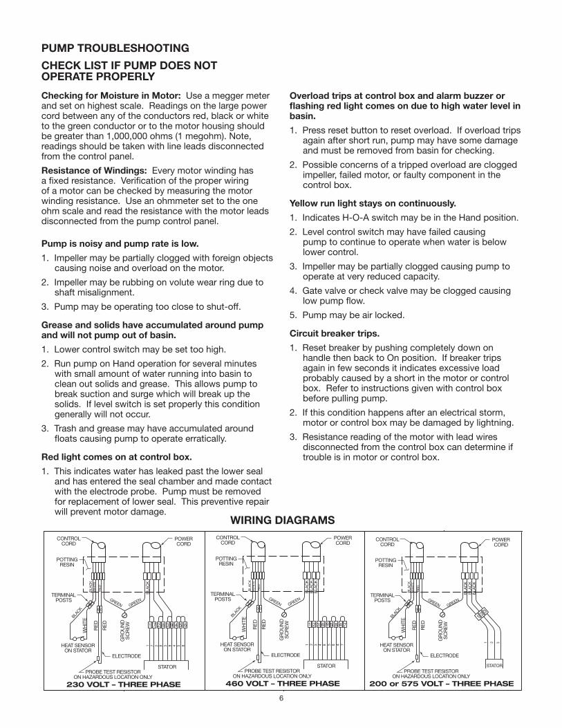
Motor Power Cord, Control Cord and Cord Cap Assembly: Each motor power cord has 4 conductors – white, black, red and green. For a three phase motor the red, black and white conductors connect to the three line leads, and the green is connected to a good ground. Interchanging any two leads will reverse the rotation of the motor.
Note: Rotation should be clockwise when observed from the top of the pump. This can be checked by noting which direction the pump torque is upon initial starting. A properly rotating pump will torque counter- clockwise upon start.
The control cable has 5 conductors – black, white, red, orange and green. White and black connect to the heat sensor terminals in the control panels; red and orange connect to the seal failure terminals in the control panel; and the green connects to the ground in the control panel.
4
The cord cap is epoxy potted. The cord cap provides for a sealed wire connection with terminals so that connections can be made without breaking the motor seal. This allows the cord cap, with cords, to be removed from the motor. An approved hazardous location junction box is required for hazardous locations.
Note: Each cable has a green ground wire and must be properly grounded per the National Electric Code and local codes.
Electrical Motor Controls: All electrical controls and motor equipment should be as specified in these instructions. Consult factory for any acceptable alternatives. For hazardous locations the controls and control panel must be installed outside the hazardous area, or approved hazardous location controls that are intrinsically safe must be used.
Junction Box: If a junction box is used in a hazardous location, it must be a hazardous location approved type with hazardous location cord connectors. Wires from the junction box must pass through a hazardous location seal connector.
Level Sensing Controls: Intrinsically safe type float controls are recommended for all applications and required for hazardous location service. An intrinsically safe control panel relay will limit the current and voltage to the level controls. A Myers® control panel can be supplied with this type circuitry.
The float level controls maintain the basin sewage water level by controlling pump turn-on and turn-off levels.
1. The lower turn-off control should be set so that the pump stops at approximately the top of the pump. Consult the factory for any settings below this point.
2. The upper turn-on control should be set above the lower turn-off control. The exact height between the controls is determined by the number of pump starts desired and the depth of the basin. A maximum of 10 starts per hour should not be exceeded.
3. The override control is set at a specified height above the upper turn-on control.
4. The alarm control is set about 6" to 12" above the override control.
5. No control should be set above the inlet invert.
Electrical Connections: All electrical wiring must be in accordance with local code and only qualified electricians should make the installations. All wires should be checked for shorts to ground with an ohmmeter or megger after the connections are made. This is important, as one grounded wire can cause failure of the pump, control panel or personal injury.
Pump: The fluid end of the pump is field serviceable and can be disassembled in case of wear, damage, plugging or outboard seal failure. The following will describe the disassembly and reassembly process.
Disassembly 1. With the pump located in a secure place, remove
the bolts fastening the seal housing to the volute. The motor and impeller can now be removed as a unit.
2. Lay the unit down on its side. If the lower seal is to be removed, it is recommended that the oil in the seal chamber be drained. This can be done by removing the lower seal chamber plug and draining the oil into a holding container.
3. To remove the impeller, first remove the bolts from the nose cone. The nose cone will pull off. Using a proper wrench, the impeller retaining bolt and washer must be removed. This may require a piece of wood placed between the vanes to keep the impeller from rotating while removing the bolt. Once the bolt has been removed, tap lightly with a hammer around the outside diameter of the impeller to loosen from tapered shaft and key.
CAUTION – The impeller is large and heavy and will need to be supported.
4. If the lower seal needs to be removed, first remove the compression spring that rides between the impeller and the seal assembly. Next remove the compression ring that surrounds the rubber bellows on the rotating portion of the seal assembly. Again using screwdrivers, pry the remaining portion of the rotating seal assembly off the shaft. The ceramic stationary can be removed by placing a screwdriver between the rubber and the ceramic face and then prying, working around the entire diameter. Note, these parts should be discarded and a new seal assembly installed.
5. If the oil in the seal chamber was drained, examine the contents to determine if the upper seal has been damaged. Sign of grit or other abrasive material may indicate that the upper seal has also been damaged. Pressurizing the motor housing assembly between 7 and 10 psi and observing any drop in pressure will indicate if the upper seal is functioning properly.
Note: Upper seal repairs must be done at a Myers Authorized Service Center or at the Myers factory. Any unauthorized field repair voids warranty and the hazardous location approval on the Factory Mutual listed pump.
6. The wear ring can be removed from the volute for repair or replacement.
5
Reassembly 1. Remove the ceramic portion of the new seal from
the package. Brush new dielectric oil around the rubber portion of the stationary assembly and into the pocket in the seal housing. Note, keep the oil off the seal face. Without scratching the seal face, press the ceramic stationary portion into the seal housing with a Myers® seal pusher. With clean cloth, lightly wipe the face of the seal surface to make sure it is dirt free. Remove the rotating portion of the seal from the package and lubricate the inside diameter of the rubber bellows and the outside diameter of the shaft. Place the seal over the shaft (make sure the key is removed). Evenly press on the body of the rotational assembly and slide it down the shaft until the seal faces meet. Once the seal assembly is in position, place the spring over the register on the rotational portion of the seal.
2. Position the key into the seat of the shaft. Align the impeller onto the shaft, making sure that the seal spring is registered properly onto the back
side of the impeller. Insert the bolt and washer assembly into the shaft and tighten. Replace the nose cone onto the impeller. The proper Loctite® should be applied to the bolts. Install and tighten.
3. Fill the seal chamber with new dielectric oil. An air gap of 10–15% volume must be left for the expansion of the oil when it is at operating temperature.
4. The wear ring can be aligned with the retaining holes and tapped into place with a soft mallet. The proper Loctite® should be applied to the bolts. Install and tighten.
5. The motor and impeller assembly can be installed into the volute. Make sure that the impeller aligns properly with the volute. Install the volute retaining bolts and tighten.
6. Air tends to trap in the pump case when water rises in the sump or when the pump is lowered into the water after service. To vent off this air, a small hole is drilled into the volute casting. Be sure this vent hole is clean after any service work on pump. Air venting is not a problem after initial start.
WIRING DIAGRAM
6
1 7 2 8 3 9 4 5 6 1 72 83 9 456
1 2 3
POTTINGRESIN
CONTROLCORD
TERMINALPOSTS
POWERCORD
ELECTRODE
HEAT SENSORON STATOR
GR
OU
ND
SC
RE
W
RE
D
RE
D
WH
ITE
BLA
CK
BLA
CK
BLACK
RE
D
WH
ITE
GREENGREEN
PROBE TEST RESISTORON HAZARDOUS LOCATION ONLY
STATOR
A B
0 0
230 VOLT – THREE PHASE
1 7 2 6548 3 9
POTTINGRESIN
CONTROLCORD
TERMINALPOSTS
POWERCORD
ELECTRODE
HEAT SENSORON STATOR
GR
OU
ND
SC
RE
W
RE
D
RE
D
WH
ITE
BLA
CK
BLA
CK
BLACK
RE
D
WH
ITE
GREENGREEN
PROBE TEST RESISTORON HAZARDOUS LOCATION ONLY
STATOR
A B
0 0
460 VOLT – THREE PHASE
1 2 3 7484 9 5
BLA
CK
BLA
CK
POTTINGRESIN
CONTROLCORD
TERMINALPOSTS
POWERCORD
ELECTRODE
HEAT SENSORON STATOR
GR
OU
ND
SC
RE
W
RE
D
RE
D
WH
ITE
BLA
CK
BLA
CK
BLACK
RE
D
WH
ITE
GREENGREEN
PROBE TEST RESISTORON HAZARDOUS LOCATION ONLY
STATOR
A B
0 0
200 or 575 VOLT – THREE PHASE
1 2 3
BLA
CK
BLA
CK
WIRING DIAGRAMS
PUMP TROUBLESHOOTING
Overload trips at control box and alarm buzzer or flashing red light comes on due to high water level in basin.1. Press reset button to reset overload. If overload trips
again after short run, pump may have some damage and must be removed from basin for checking.
2. Possible concerns of a tripped overload are clogged impeller, failed motor, or faulty component in the control box.
Yellow run light stays on continuously.1. Indicates H-O-A switch may be in the Hand position.
2. Level control switch may have failed causing pump to continue to operate when water is below lower control.
3. Impeller may be partially clogged causing pump to operate at very reduced capacity.
4. Gate valve or check valve may be clogged causing low pump flow.
5. Pump may be air locked.
Circuit breaker trips.1. Reset breaker by pushing completely down on
handle then back to On position. If breaker trips again in few seconds it indicates excessive load probably caused by a short in the motor or control box. Refer to instructions given with control box before pulling pump.
2. If this condition happens after an electrical storm, motor or control box may be damaged by lightning.
3. Resistance reading of the motor with lead wires disconnected from the control box can determine if trouble is in motor or control box.
CHECK LIST IF PUMP DOES NOT OPERATE PROPERLYChecking for Moisture in Motor: Use a megger meter and set on highest scale. Readings on the large power cord between any of the conductors red, black or white to the green conductor or to the motor housing should be greater than 1,000,000 ohms (1 megohm). Note, readings should be taken with line leads disconnected from the control panel.
Resistance of Windings: Every motor winding has a fixed resistance. Verification of the proper wiring of a motor can be checked by measuring the motor winding resistance. Use an ohmmeter set to the one ohm scale and read the resistance with the motor leads disconnected from the pump control panel.
Pump is noisy and pump rate is low.1. Impeller may be partially clogged with foreign objects
causing noise and overload on the motor.
2. Impeller may be rubbing on volute wear ring due to shaft misalignment.
3. Pump may be operating too close to shut-off.
Grease and solids have accumulated around pump and will not pump out of basin.1. Lower control switch may be set too high.
2. Run pump on Hand operation for several minutes with small amount of water running into basin to clean out solids and grease. This allows pump to break suction and surge which will break up the solids. If level switch is set properly this condition generally will not occur.
3. Trash and grease may have accumulated around floats causing pump to operate erratically.
Red light comes on at control box.1. This indicates water has leaked past the lower seal
and has entered the seal chamber and made contact with the electrode probe. Pump must be removed for replacement of lower seal. This preventive repair will prevent motor damage.
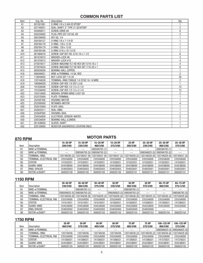
CAP SCREW TORQUE VALUE 3/8-16 20 ft.-lbs. 1/2-13 43 ft.-lbs. 5/8-11 93 ft.-lbs. 3/4-10 128 ft.-lbs. 7/8-14 193 ft.-lbs.
9
MOTOR PARTS
COMMON PARTS LISTItem Eng. No. Description Qty.A1 001501081 O-RING 1/8 x 2.484 ID VITON® 1A2 037180051 SEAL–SHAFT 3" TYPE 21 CE/VITON® 2A3 045800011 SCREW–DRIVE #6 6A4 05022A062 PLUG–PIPE SST 3/8 SQ. HD 3A5 05818A050 KEY SQ. 1/4 1A6 05876A127 O-RING 1/8 x 7-1/4 ID 1A7 05876A178 O-RING .139 x 12 ID 1A8 05876A179 O-RING .139 x 13 ID 1A9 05876A180 O-RING 3/16 x 16-1/2 ID 1
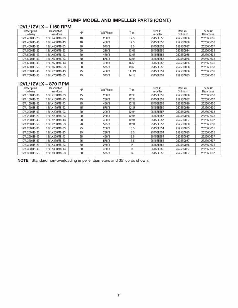
NOTE: Standard non-overloading impeller diameters and 35’ cords shown.
740 EAST 9TH STREET 490 PinEbuSH RoAd, uniT #4 ASHLAnd, oHio, uSA 44805 CAMbRidGE, onTARio, CAnAdA n1T 0A5 419-289-1144 800-363-PuMP
WWW.HYdRoMATiC.CoM
Warranty Rev. 12/13
STANDARD LIMITED WARRANTY
Pentair Hydromatic® warrants its products against defects in material and workmanship for a period of 12 months from the date of shipment from Pentair Hydromatic or 18 months from the manufacturing date, whichever occurs first – provided that such products are used in compliance with the requirements of the Pentair Hydromatic catalog and technical manuals for use in pumping raw sewage, municipal wastewater or similar, abrasive-free, noncorrosive liquids.
during the warranty period and subject to the conditions set forth, Pentair Hydromatic, at its discretion, will repair or replace to the original user, the parts that prove defective in materials and workmanship. Pentair Hydromatic reserves the right to change or improve its products or any portions thereof without being obligated to provide such a change or improvement for prior sold and/or shipped units.
Start-up reports and electrical schematics may be required to support warranty claims. Submit at the time of start up through the Pentair Hydromatic website: http://forms.pentairliterature.com/startupform/startupform.asp?type=h. Warranty is effective only if Pentair Hydromatic authorized control panels are used. All seal fail and heat sensing devices must be hooked up, functional and monitored or this warranty will be void. Pentair Hydromatic will cover only the lower seal and labor thereof for all dual seal pumps. under no circumstance will Pentair Hydromatic be responsible for the cost of field labor, travel expenses, rented equipment, removal/reinstallation costs or freight expenses to and from the factory or an authorized Pentair Hydromatic service facility.This limited warranty will not apply: (a) to defects or malfunctions resulting from failure to properly install, operate or maintain the unit in accordance with the printed instructions provided; (b) to failures resulting from abuse, accident or negligence; (c) to normal maintenance services and parts used in connection with such service; (d) to units that are not installed in accordance with applicable local codes, ordinances and good trade practices; (e) if the unit is moved from its original installation location; (f) if unit is used for purposes other than for what it is designed and manufactured; (g) to any unit that has been repaired or altered by anyone other than Pentair Hydromatic or an authorized Pentair Hydromatic service provider; (h) to any unit that has been repaired using non factory specified/oEM parts.
Warranty Exclusions: PEnTAiR HYdRoMATiC MAKES no EXPRESS oR iMPLiEd WARRAnTiES THAT EXTEnd bEYond THE dESCRiPTion on THE FACE HEREoF. PEnTAiR HYdRoMATiC SPECiFiCALLY diSCLAiMS THE iMPLiEd WARRAnTiES oF MERCHAnTAbiLiTY And FiTnESS FoR AnY PARTiCuLAR PuRPoSE.
Liability Limitation: in no EVEnT SHALL PEnTAiR HYdRoMATiC bE LiAbLE oR RESPonSibLE FoR ConSEQuEnTiAL, inCidEnTAL oR SPECiAL dAMAGES RESuLTinG FRoM oR RELATEd in AnY MAnnER To AnY PEnTAiR HYdRoMATiC PRoduCT oR PARTS THEREoF. PERSonAL inJuRY And/oR PRoPERTY dAMAGE MAY RESuLT FRoM iMPRoPER inSTALLATion. PEnTAiR HYdRoMATiC diSCLAiMS ALL LiAbiLiTY, inCLudinG LiAbiLiTY undER THiS WARRAnTY, FoR iMPRoPER inSTALLATion. PEnTAiR HYdRoMATiC RECoMMEndS inSTALLATion bY PRoFESSionALS.
Some states do not permit some or all of the above warranty limitations or the exclusion or limitation of incidental or consequential damages and therefore such limitations may not apply to you. no warranties or representations at any time made by any representatives of Pentair Hydromatic shall vary or expand the provision hereof.


![Submersible Mixer Type ABS RW 400 and 650 [NG] Submersible ...](https://static.documents.pub/doc/80x56/61be4e22f4c05341d03d7f57/submersible-mixer-type-abs-rw-400-and-650-ng-submersible-.jpg)


