Submission doc.: IEEE 11-13/0536r0 May 2013 Wookbong Lee, LG Electronics Slide 1 HEW SG PHY Considerations For Outdoor Environment Date: 2013-05-12 N am e A ffiliations A ddress Phone em ail W ookbong Lee LG Electronics G yeonggi-do, K orea +82-31-450- 1883 wookbong.lee@lge. com Jinyoung Chun LG Electronics [email protected]Jinsoo Choi LG Electronics [email protected]D ongguk Lim LG Electronics [email protected]om H anG yu Cho LG Electronics [email protected]Authors:
Transcript
Submission
doc.: IEEE 11-13/0536r0May 2013
Wookbong Lee, LG ElectronicsSlide 1
HEW SG PHY Considerations For Out-door Environment
Date: 2013-05-12
Name Affiliations Address Phone email Wookbong Lee LG Electronics Gyeonggi-do, Korea +82-31-450-
This document includes PHY considerations for HEW development especially for Outdoor Environment.
Submission
doc.: IEEE 11-13/0536r0May 2013
Wookbong Lee, LG ElectronicsSlide 3
Introduction
• IEEE 802.11a/b/g/n/ac have been developed focusing on
indoor usage cases.
• Even though the indoor usage case will be one of the ma-
jor environment for HEW project, we also need to con-
sider outdoor environment as well. [1]
• Outdoor channel environment is quite different from in-
door channel model as measured and modelled in [2][3].
• In this contribution, we analyze major characteristics of
outdoor channel model (urban macro cell (UMa)).
Submission
doc.: IEEE 11-13/0536r0
Wookbong Lee, LG Electronics
Delay Spread• Following figures shows CDF of the maximum excess
delay for UMa channel model at 2.4GHz
Slide 4
May 2013
User Loca-tion
Average SNR (dB)
95% Max Excess
Delay (ns)
30m 42.6 806
100m 27.3 1330
500m 0.3 1540
0 0.2 0.4 0.6 0.8 1 1.2 1.4 1.6 1.8 20
0.1
0.2
0.3
0.4
0.5
0.6
0.7
0.8
0.9
1
delay [us]
CD
F
2.4GHz, UMa
30m100m300m
Submission
doc.: IEEE 11-13/0536r0
Wookbong Lee, LG Electronics
Delay Spread• Following figures shows CDF of the maximum excess
delay for UMa channel model at 5GHz
Slide 5
May 2013
User Loca-tion
Average SNR (dB)
95% Max Excess
Delay (ns)
30m 36.5 804
100m 21 1344
500m -4 1546
0 0.2 0.4 0.6 0.8 1 1.2 1.4 1.6 1.8 20
0.1
0.2
0.3
0.4
0.5
0.6
0.7
0.8
0.9
1
delay[us]
CD
F
5GHz,UMa
30m100m300m
Submission
doc.: IEEE 11-13/0536r0
Wookbong Lee, LG Electronics
Impact of Larger Delay Spread
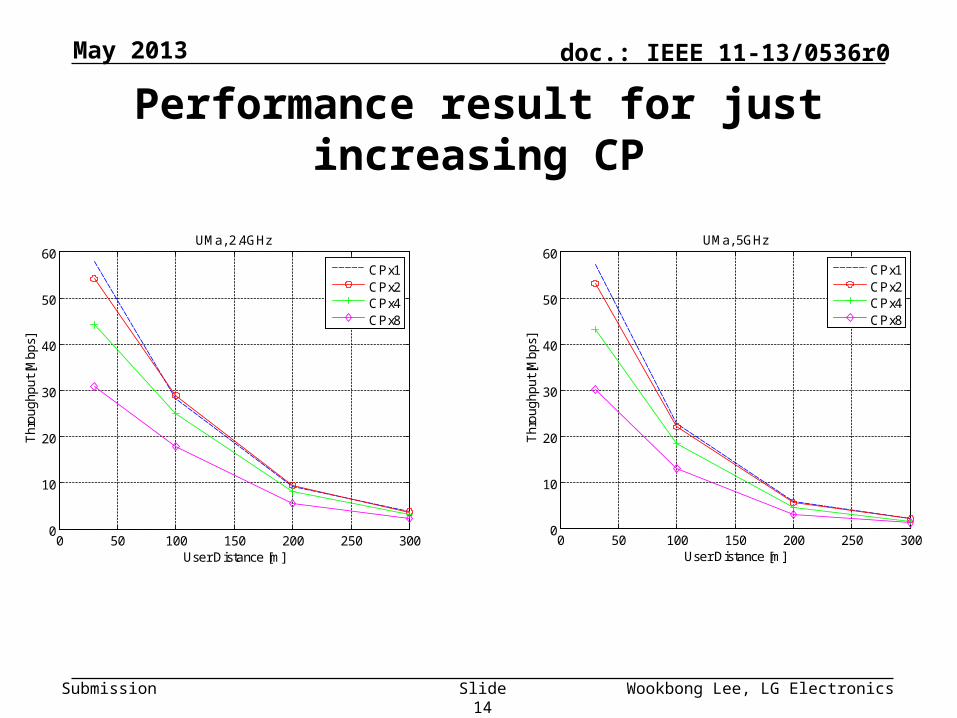
• Performance loss due to larger inter-symbol-interference.
• There is no other solution than increasing CP length in this case.
• Just increasing CP length brings throughput loss due to larger PHY overhead. (See Appendix for more details)
• During the development of IEEE 802.11af or .11ah, members come up with increasing CP length by increasing FFT size for a given bandwidth to maintain physical layer overhead.
─ For example, the subcarrier spacing of .11af is 41.7kHz (in case of U.S. channel) and that of .11ah is 31.25kHz while the subcarrier spacing of .11a/n/ac is 312.5kHz.
• With same logic, we can increase CP length by increasing FFT size for a given bandwidth (20MHz, 40MHz, 80MHz or 160MHz).
Slide 6
May 2013
Submission
doc.: IEEE 11-13/0536r0
Wookbong Lee, LG Electronics
Impact of Larger Delay Spread
Slide 7
May 2013
User Location @ 100m
Performance gain over FFT 64 (%)
FFT 128 22.2%
FFT 256 39.4%
FFT 512 47.7%
0 50 100 150 200 250 3000
10
20
30
40
50
60
70
User Distance [m]
Th
rou
gh
pu
t [M
bp
s]
UMa, 2.4GHz
FFT 64FFT 128FFT 256FFT 512
Submission
doc.: IEEE 11-13/0536r0
Wookbong Lee, LG Electronics
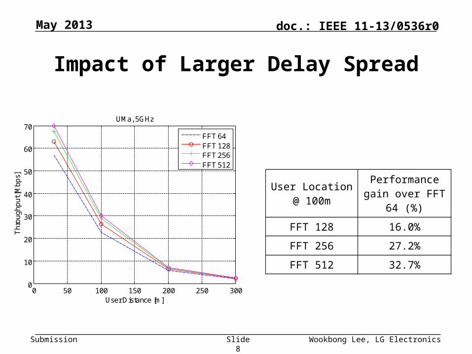
Impact of Larger Delay Spread
Slide 8
May 2013
User Location @ 100m
Performance gain over FFT 64 (%)
FFT 128 16.0%
FFT 256 27.2%
FFT 512 32.7%
0 50 100 150 200 250 3000
10
20
30
40
50
60
70
User Distance [m]
Th
rou
gh
pu
t [M
bp
s]
UMa, 5GHz
FFT 64FFT 128FFT 256FFT 512
Submission
doc.: IEEE 11-13/0536r0
Wookbong Lee, LG Electronics
Channel Variation
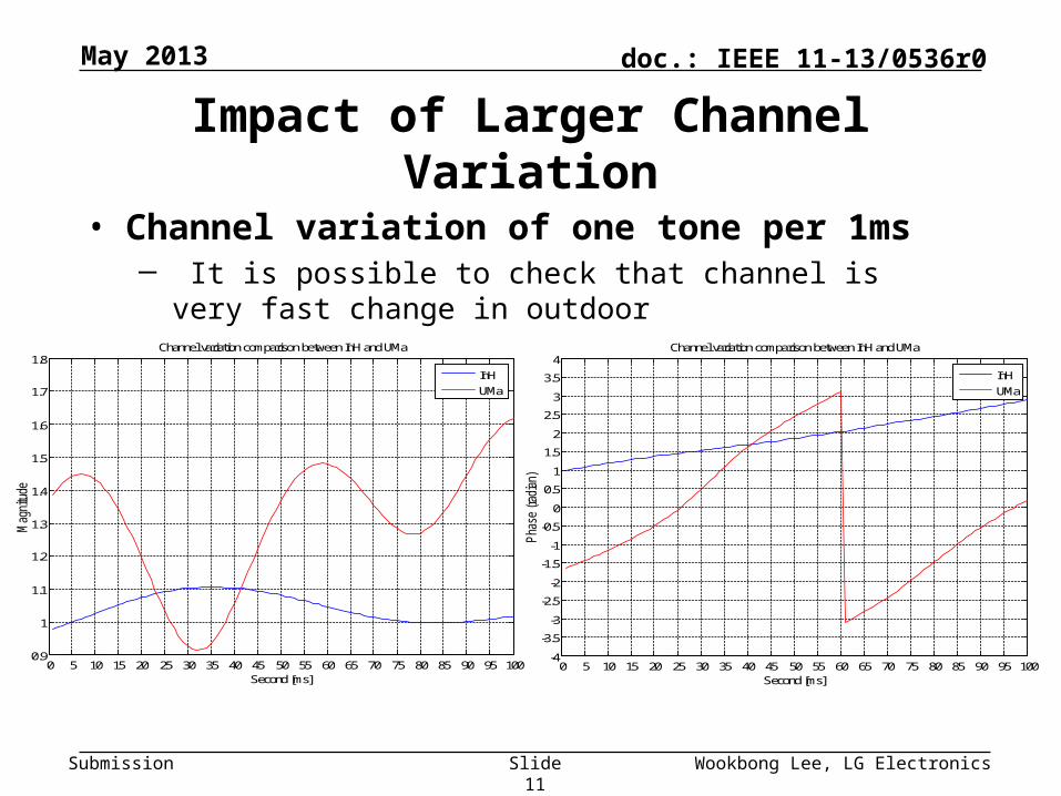
• In outdoor channel, per tone channel is varying faster than that in indoor channel due to faster environmental change as well as more channel tap (more multi-path)
Slide 9
May 2013
Submission
doc.: IEEE 11-13/0536r0
Wookbong Lee, LG Electronics
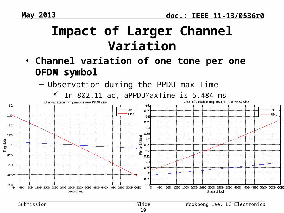
Impact of Larger Channel Variation
Slide 10
May 2013
• Channel variation of one tone per one OFDM symbol ─ Observation during the PPDU max Time
Need to minimize per-formance loss due to larger inter-symbol-in-terference
•Larger CP length by increasing CP portion versus symbol duration- Pros: Robustness against delay spread in outdoor - Cons: Throughput loss from increased CP portion
•Larger CP length by increasing FFT size - Pros: Robustness against delay spread in outdoor and no direct throughput loss- Cons: Possible impact on PPDU design by diff. OFDM nu-merology
Larger chan-nel variation
Need to compensate per-formance loss due to dis-torted channel informa-tion
•Channel estimation improvement- Accurate channel estimation (e.g. pilot, midamble)•Channel feedback improvement- Efficient feedback (e.g. Effective SINR (ESINR) feedback, codebook based channel information, fast feedback channel)•Techniques to mitigate fading- Enhancement of link quality (e.g. effective error correction and retransmission mechanism)


![[]MOEEEEEEIBIIE EEEEMhhEMhhEEE mEDBDBomEohhhI 'HEW](https://static.documents.pub/doc/80x56/6230a28aec3e0f2f972e9688/moeeeeeeibiie-eeeemhhemhheee-medbdbomeohhhi-hew.jpg)


