Firetrol Remote Alarm Panelsfor Use With Diesel Engine and Electric Fire Pump ControllersFTA200-A, 200-AA, 200-F, 200-FF & 200-AFSpecifications
1.0 Alarm PanelThe main fire pump controller shall be a factory assembled, wired and tested unit.
1.1 Standards, Listings & ApprovalsThe controller shall conform to all the requirements of the latest editions of:NFPA 20, Standard for the Installation of Stationary Pumps for Fire ProtectionNFPA 70, National Electrical Code.Factory Mutual (FM)
The controller shall be listed by:Underwriters Laboratories, Inc., in accordance with UL508, Standard for Industrial ControlsCanadian Standards Association CSA-C22.2, Standard for Industrial Control Equip-ment (cUL)
1.2 EnclosureThe controller components shall be housed in a NEMA Type 1 (IEC IP20) drip-proof, wall mounted enclosure with bottom entry gland plate.
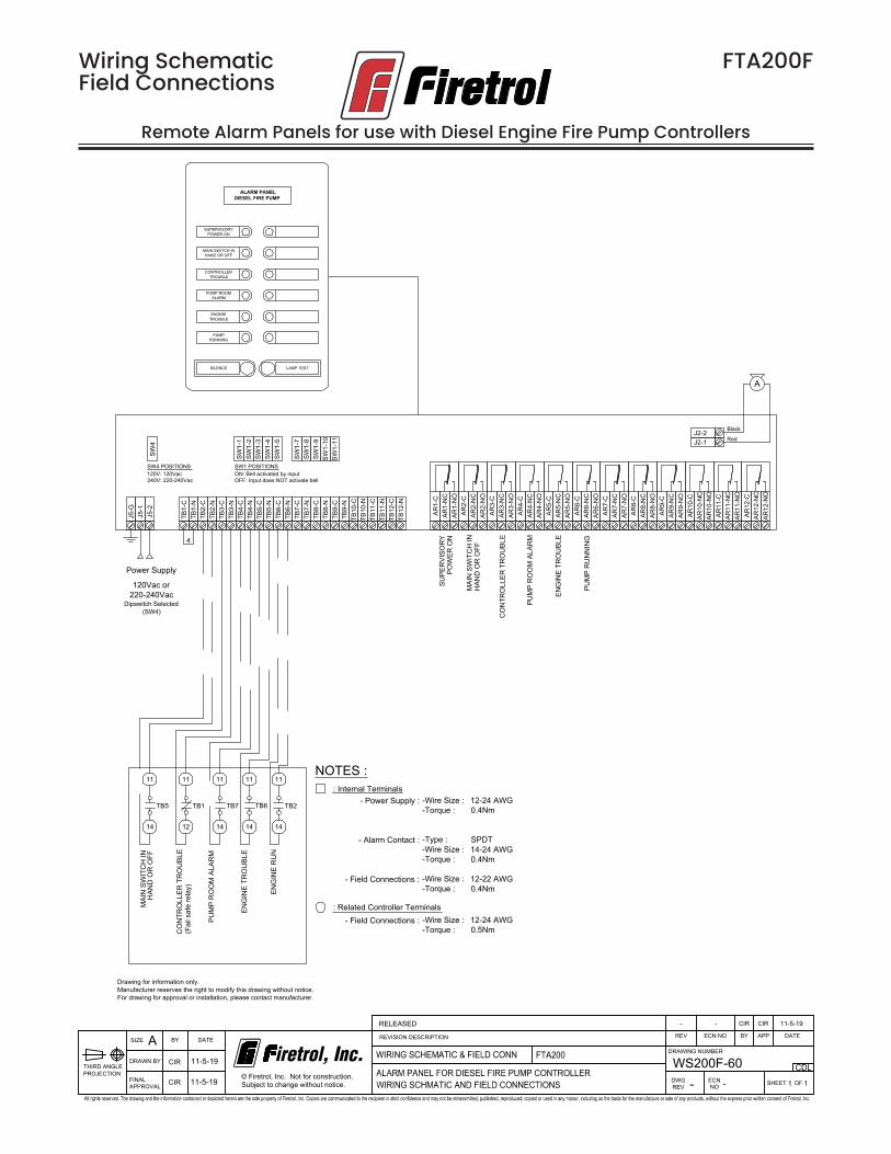
1.3 OperationThe alarm panel shall have individual LED lights to indicate its alarm condition which shall remain lighted until the alarm condition has been corrected. The alarm panel shall also have an audible alarm which will sound when the alarm conditions occur and may be silenced by pressing a SILENCE ALARM push-button.Each alarm initiation shall be subsequent to any and all previous alarm conditions so that the silence push-button acknowledgment of any one alarm will not prevent the audible alarm from sounding on successive alarm conditions.The alarm panel shall have a PUSH-TO-TEST push-button for manually testing all LED lights, audible alarms and output circuits. All alarm LED’s and push-buttons shall be plainly marked for identification.
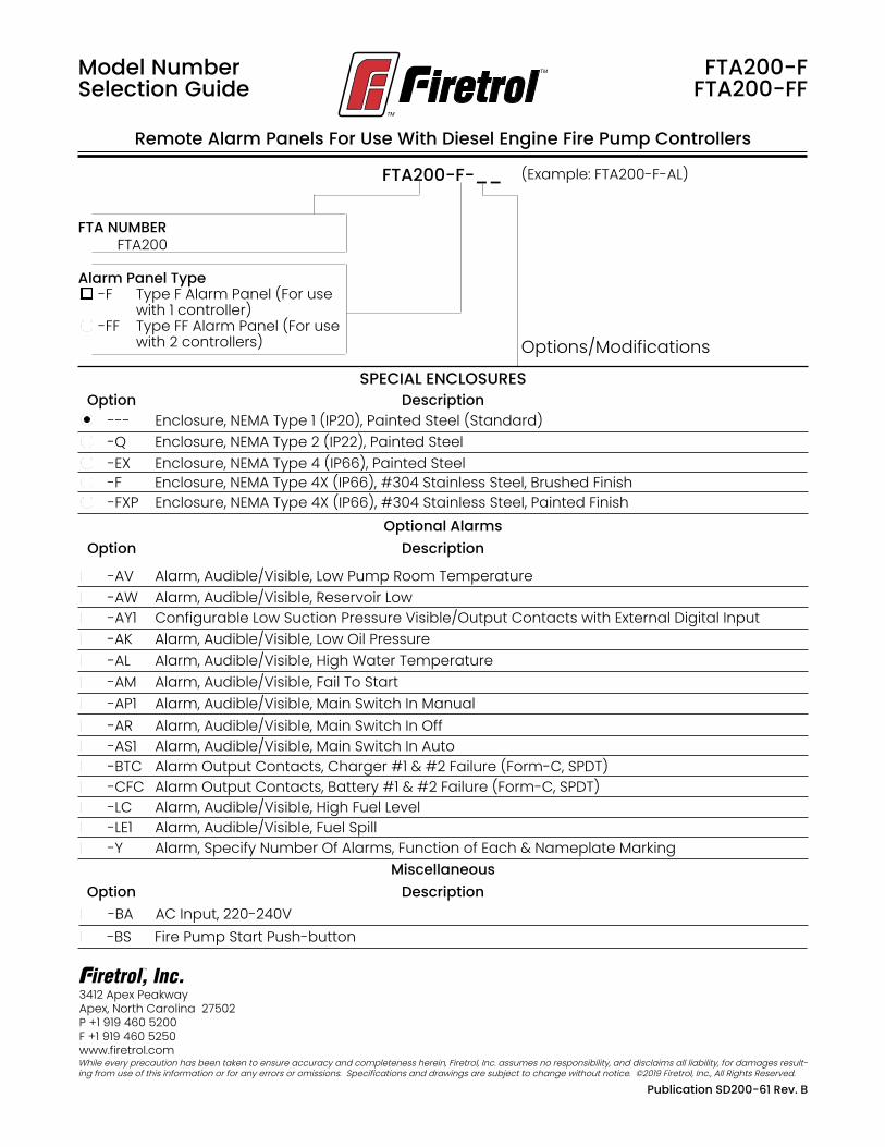
1.4 ManufacturerThe alarm panel shall be a Firetrol model FTA200-A for use with electric fire pump controllers, FTA200-AA for use with 2 electric fire pump controllers or model FTA200-F for use with diesel engine fire pump controllers, FTA200-FF for use with 2 diesel en-gine fire pump controllers or a FTA200-AF for use with 1 electric fire pump controller and 1 diesel engine fire pump controller.
Description—Firetrol® FTA200 alarm panels are designed to meet the NPFA 20 speci-fications requiring a remote alarm panel when the pump house or pump room is not constantly attended. The alarm panel must be installed in a location that is un-der supervision at all times.
Approvals—These alarm panels are listed by Underwriter’s Laboratories, Inc., in ac-cordance with UL508, Standard for Indus-trial Controls, certified by CSA, Standard for Industrial Control Equipment (cUL) and approved by Factory Mutual. They are designed to meet or exceed the require-ments of the approving authorities listed above as well as NFPA 20, Installation of Centrifugal Fire Pumps.
Standard Features—The following are in-cluded as standard with each controller:
Type F - Type F panels provide alarm indi-cation for the following conditions:• Supervisory Power On (Visible Only)• Main Switch In Hand or Off (Audible and
Visible)• Controller Trouble (Audible and Visible)
• Pump Room Alarm (Audible and Visible)• Engine Trouble (Audible and Visible)• Engine Running (Audible and Visible)
Type FF - Type FF panels provide audible and visible alarm indications for 2 sepa-rate diesel engine controllers utilizing 1 alarm panel enclosure.
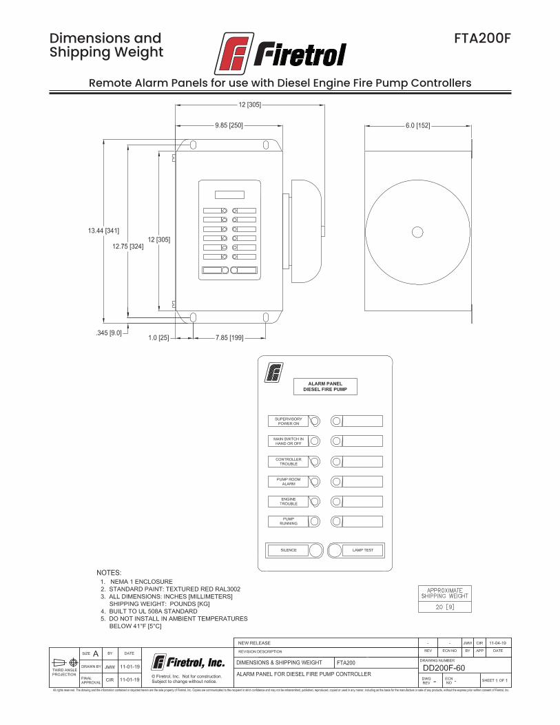
Construction - FTA200 alarm panels make use of printed circuit boards which pro-vide reliable and trouble free service. The enclosures are NEMA Type 1 (IEC IP20) for indoor wall mounting. A bottom entry gland plate is provided in the enclosure. The standard enclosure color is red. Mounted on the enclosure door are the LED lights for visible alarm indication, the SILENCE ALARM push-button and the LAMP TEST push-button. An alarm bell for audible indication is mounted on the side of the enclosure. Each LED will illuminate to indicate its alarm condition and will remain lighted until the abnormal condition has been corrected. The audible alarm will sound when the alarm conditions occur and will continue to sound until the abnormal con-dition has been corrected or the SILENCE ALARM push-button has been pressed. Pressing the SILENCE ALARM push-button will silence the audible alarm but will not extinguish the LED. If another alarm condi-tion occurs the audible alarm will again sound until silenced by the SILENCE ALARM push-button or until the abnormal condi-tion has been corrected. The LAMP TEST push-button is supplied for manually testing the LED’s.
Product Description FTA200-FFTA200-FF
Remote Alarm Panels for use with Diesel Engine Fire Pump Controllers
Remote Alarm Panels For Use With Diesel Engine Fire Pump Controllers
Model Number Selection Guide
FTA200-FFTA200-FF
SPECIAL ENCLOSURES DescriptionOption
-Q Enclosure, NEMA Type 2 (IP22), Painted Steel -EX Enclosure, NEMA Type 4 (IP66), Painted Steel
-FXP Enclosure, NEMA Type 4X (IP66), #304 Stainless Steel, Painted Finish
--- Enclosure, NEMA Type 1 (IP20), Painted Steel (Standard)
-AV Alarm, Audible/Visible, Low Pump Room Temperature
Optional Alarms DescriptionOption
-AW Alarm, Audible/Visible, Reservoir Low -AY1 Configurable Low Suction Pressure Visible/Output Contacts with External Digital Input -AK Alarm, Audible/Visible, Low Oil Pressure -AL Alarm, Audible/Visible, High Water Temperature -AM Alarm, Audible/Visible, Fail To Start -AP1 Alarm, Audible/Visible, Main Switch In Manual -AR Alarm, Audible/Visible, Main Switch In Off -AS1 Alarm, Audible/Visible, Main Switch In Auto -BTC Alarm Output Contacts, Charger #1 & #2 Failure (Form-C, SPDT) -CFC Alarm Output Contacts, Battery #1 & #2 Failure (Form-C, SPDT) -LC Alarm, Audible/Visible, High Fuel Level -LE1 Alarm, Audible/Visible, Fuel Spill
-BS Fire Pump Start Push-button
Miscellaneous DescriptionOption
-BA AC Input, 220-240V
-Y Alarm, Specify Number Of Alarms, Function of Each & Nameplate Marking
Options/Modifications
-F Enclosure, NEMA Type 4X (IP66), #304 Stainless Steel, Brushed Finish
Dimensions andShipping Weight
Remote Alarm Panels for use with Diesel Engine Fire Pump Controllers
FTA200F
Dimensions andShipping Weight
Remote Alarm Panels for use with (2) Diesel Engine Fire Pump Controllers
FTA200FF
Drawing for information only.Manufacturer reserves the right to modify this drawing without notice.For drawing for approval or installation, please contact manufacturer.
TB6-
NTB
6-C
TB5-
NTB
5-C
TB4-
NTB
4-C
TB3-
NTB
3-C
TB2-
NTB
2-C
TB1-
NTB
1-C
J5-2
J5-1
SW1-
5SW
1-4
SW1-
3SW
1-2
SW1-
1 J2-1J2-2
A
ON: Bell activated by input
Red
Black
OFF: Input does NOT activate bell
SW1 POSITIONS
J5-G AR
1-C
AR1-
NC
AR1-
NO
AR2-
CAR
2-N
CAR
2-N
OAR
3-C
AR3-
NC
AR3-
NO
AR4-
CAR
4-N
CAR
4-N
OAR
5-C
AR5-
NC
AR5-
NO
AR6-
CAR
6-N
CAR
6-N
OAR
7-C
AR7-
NC
AR7-
NO
AR8-
CAR
8-N
CAR
8-N
OAR
9-C
AR9-
NC
AR9-
NO
AR10
-CAR
10-N
CAR
10-N
OAR
11-C
AR11
-NC
AR11
-NO
AR12
-CAR
12-N
CAR
12-N
O
SW1-
11SW
1-10
SW1-
9SW
1-8
SW1-
7
SUPE
RVI
SOR
YPO
WER
ON4
Power Supply
ALARM PANELDIESEL FIRE PUMP
SUPERVISORYPOWER ON
SILENCE LAMP TEST
TB5 TB1 TB7
11
14
11
14
11
12
11
14
TB12
-NTB
12-C
TB11
-NTB
11-C
TB10
-NTB
10-C
TB9-
NTB
9-C
TB8-
NTB
8-C
TB7-
NTB
7-C
11
14
TB6 TB2
CONTROLLERTROUBLE
PUMPRUNNING
ENGINETROUBLE
MAIN SWITCH INHAND OR OFF
PUMP ROOMALARM
CO
NTR
OLL
ER T
RO
UBL
E
PUM
P R
UN
NIN
G
ENG
INE
TRO
UBL
E
PUM
P R
OO
M A
LAR
M
MAI
N S
WIT
CH
INH
AND
OR
OFF
ENG
INE
TRO
UBL
E
MAI
N S
WIT
CH
IN
ENG
INE
RU
N
(Fai
l saf
e re
lay)
CO
NTR
OLL
ER T
RO
UBL
E
HAN
D O
R O
FF
PUM
P R
OO
M A
LAR
M
120Vac or220-240Vac
Dipswitch Selected(SW4)
SW4
SW4 POSITIONS120V: 120Vac240V: 220-240Vac
NOTES :: Internal Terminals
-Wire Size :-Torque :
-Type :-Wire Size :-Torque :
-Wire Size :-Torque :
- Power Supply :
- Alarm Contact :
- Field Connections :
12-24 AWG0.4Nm
SPDT14-24 AWG0.4Nm
12-22 AWG0.4Nm
: Related Controller Terminals-Wire Size :-Torque :
Remote Alarm Panels for use with Diesel Engine Fire Pump Controllers
FTA200F
Drawing for information only.Manufacturer reserves the right to modify this drawing without notice.For drawing for approval or installation, please contact manufacturer.
TB6-
NTB
6-C
TB5-
NTB
5-C
TB4-
NTB
4-C
TB3-
NTB
3-C
TB2-
NTB
2-C
TB1-
NTB
1-C
J5-2
J5-1
SW1-
5SW
1-4
SW1-
3SW
1-2
SW1-
1 J2-1J2-2
A
ON: Bell activated by input
Red
Black
OFF: Input does NOT activate bell
SW1 POSITIONS
J5-G AR
1-C
AR1-
NC
AR1-
NO
AR2-
CAR
2-N
CAR
2-N
OAR
3-C
AR3-
NC
AR3-
NO
AR4-
CAR
4-N
CAR
4-N
OAR
5-C
AR5-
NC
AR5-
NO
AR6-
CAR
6-N
CAR
6-N
OAR
7-C
AR7-
NC
AR7-
NO
AR8-
CAR
8-N
CAR
8-N
OAR
9-C
AR9-
NC
AR9-
NO
AR10
-CAR
10-N
CAR
10-N
OAR
11-C
AR11
-NC
AR11
-NO
AR12
-CAR
12-N
CAR
12-N
O
TB12
-NTB
12-C
TB11
-NTB
11-C
TB10
-NTB
10-C
TB9-
NTB
9-C
TB8-
NTB
8-C
TB7-
NTB
7-C
SW1-
11SW
1-10
SW1-
9SW
1-8
SW1-
7
SUPE
RVI
SOR
YPO
WER
ON
4
Power Supply
DUAL ALARM PANELDIESEL FIRE PUMPS
SUPERVISORYPOWER ON
SILENCE LAMP TEST
CONTROLLERTROUBLE - PUMP 2
PUMP 2RUNNING
ENGINE TROUBLEPUMP 2
MAIN SWITCH INHAND/OFF - PUMP 2
11
TB1
14
11
12
ENG
INE
TRO
UBL
E
TB6
MAI
N S
WIT
CH
IN
TB7
ENG
INE
RU
N
(Fai
l saf
e re
lay)
CO
NTR
OLL
ER T
RO
UBL
E
11
14
11
14
11
14
CO
NTR
OLL
ER T
RO
UBL
E
PUM
P R
UN
NIN
G
ENG
INE
TRO
UBL
E
TB5 TB1 TB7 TB6
11
14
11
14
11
14
11
12
11
14
HAN
D O
R O
FF
PUM
P R
OO
M A
LAR
M
TB2
PUM
P R
OO
M A
LAR
M
MAI
N S
WIT
CH
INH
AND
OR
OFF
PUMP ROOMALARM - PUMP 2
TB5
CONTROLLERTROUBLE - PUMP 1
PUMP 1 RUNNING
ENGINE TROUBLEPUMP 1
MAIN SWITCH INHAND/OFF - PUMP 1
PUMP ROOMALARM - PUMP 1
CO
NTR
OLL
ER T
RO
UBL
E
PUM
P R
UN
NIN
G
ENG
INE
TRO
UBL
E
PUM
P R
OO
M A
LAR
M
MAI
N S
WIT
CH
INH
AND
OR
OFF
ENG
INE
TRO
UBL
E
MAI
N S
WIT
CH
IN
ENG
INE
RU
N
CO
NTR
OLL
ER T
RO
UBL
E
HAN
D O
R O
FF
PUM
P R
OO
M A
LAR
M
TB2
120Vac or220-240Vac
Dipswitch Selected(SW4)
SW4
SW4 POSITIONS120V: 120Vac240V: 220-240Vac
NOTES :: Internal Terminals
-Wire Size :-Torque :
-Type :-Wire Size :-Torque :
-Wire Size :-Torque :
- Power Supply :
- Alarm Contact :
- Field Connections :
12-24 AWG0.4Nm
SPDT14-24 AWG0.4Nm
12-22 AWG0.4Nm
: Related Controller Terminals-Wire Size :-Torque :