Subpixel-based Down-sampling via Min-MaxDirectional Error
Lu Fang, Oscar C. AuDepartment of Electronic and Computer EngineeringHong Kong University of Science and Technology
Email: {fanglu, eeau}@ust.hk
Abstract— Subpixel-based down-sampling is a method that canpotentially improve the apparent resolution of a down-scaledimage by controlling individual subpixels rather than pixels.However, the increased luminance resolution often comes at theexpense of chrominance distortion. In this paper, we formulatethe subpixel-based down-sampling as a Min-Max problem (Min-Max Directional Error) which we call MMDE. Unfortunately,the solution of MMDE is computational intensive, especiallyfor large images. We thus relax the MMDE by determiningthe maximum error based on HVS, which largely reduces thenumber of constraints. We call such relaxation as MMDE-VR(Visual Relaxation). Simulation results illustrate that MMDE-VR can effectively reduce visible color fringing artifacts whilestill maintaining sharpness.
I. BACKGROUND ON SUBPIXEL-BASED DOWN-SAMPLING
Often we need to shrink a high resolution image (e.g. 10-mega pixel or HDTV) in order to display it on a low resolutiondisplay (e.g digital camera, mobile phone, portable DVD).A simple way which we called Direct Pixel-based Down-sampling (DPD) performs simple down-sampling by selectingone out of every N pixels. It can incur severe aliasing artifactsin regions with high spatial frequency. An improved schemeis called Pixel-based Down-sampling with Anti-aliasing Filter(PDAF) in which an anti-aliasing filter is applied before DPDto suppress aliasing artifacts. But it smooths the result atthe cost of blurring the image, as only the low frequencyinformation can be retained in the process.
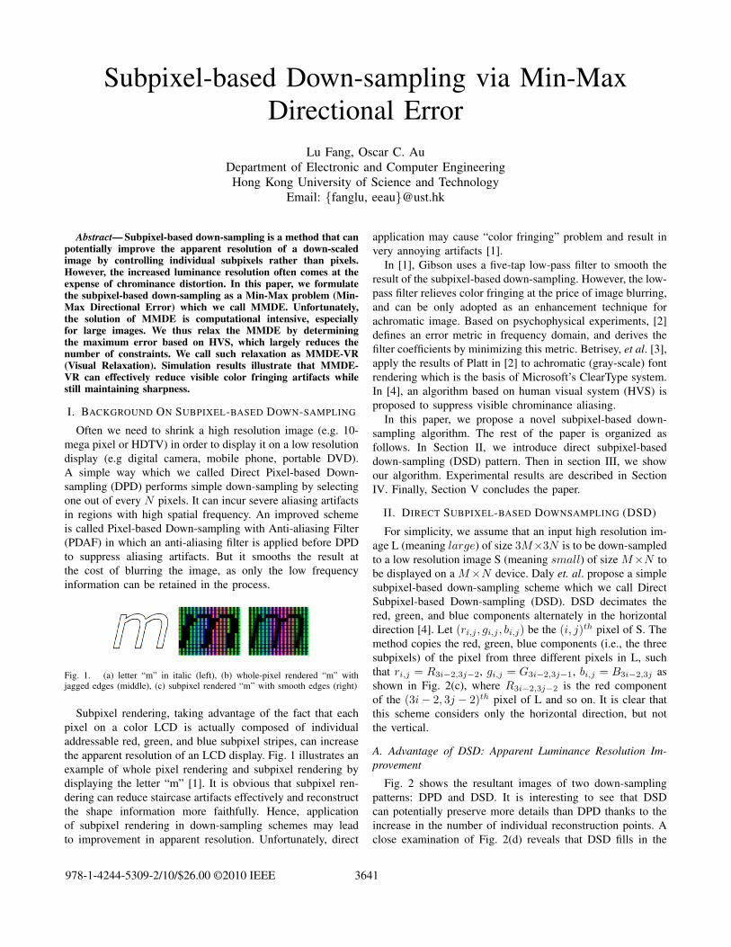
Fig. 1. (a) letter “m” in italic (left), (b) whole-pixel rendered “m” withjagged edges (middle), (c) subpixel rendered “m” with smooth edges (right)
Subpixel rendering, taking advantage of the fact that eachpixel on a color LCD is actually composed of individualaddressable red, green, and blue subpixel stripes, can increasethe apparent resolution of an LCD display. Fig. 1 illustrates anexample of whole pixel rendering and subpixel rendering bydisplaying the letter “m” [1]. It is obvious that subpixel ren-dering can reduce staircase artifacts effectively and reconstructthe shape information more faithfully. Hence, applicationof subpixel rendering in down-sampling schemes may leadto improvement in apparent resolution. Unfortunately, direct
application may cause “color fringing” problem and result invery annoying artifacts [1].
In [1], Gibson uses a five-tap low-pass filter to smooth theresult of the subpixel-based down-sampling. However, the low-pass filter relieves color fringing at the price of image blurring,and can be only adopted as an enhancement technique forachromatic image. Based on psychophysical experiments, [2]defines an error metric in frequency domain, and derives thefilter coefficients by minimizing this metric. Betrisey, et al. [3],apply the results of Platt in [2] to achromatic (gray-scale) fontrendering which is the basis of Microsoft’s ClearType system.In [4], an algorithm based on human visual system (HVS) isproposed to suppress visible chrominance aliasing.
In this paper, we propose a novel subpixel-based down-sampling algorithm. The rest of the paper is organized asfollows. In Section II, we introduce direct subpixel-baseddown-sampling (DSD) pattern. Then in section III, we showour algorithm. Experimental results are described in SectionIV. Finally, Section V concludes the paper.
II. DIRECT SUBPIXEL-BASED DOWNSAMPLING (DSD)
For simplicity, we assume that an input high resolution im-age L (meaning large) of size 3M×3N is to be down-sampledto a low resolution image S (meaning small) of size M×N tobe displayed on a M×N device. Daly et. al. propose a simplesubpixel-based down-sampling scheme which we call DirectSubpixel-based Down-sampling (DSD). DSD decimates thered, green, and blue components alternately in the horizontaldirection [4]. Let (ri,j , gi,j , bi,j) be the (i, j)th pixel of S. Themethod copies the red, green, blue components (i.e., the threesubpixels) of the pixel from three different pixels in L, suchthat ri,j = R3i−2,3j−2, gi,j = G3i−2,3j−1, bi,j = B3i−2,3j asshown in Fig. 2(c), where R3i−2,3j−2 is the red componentof the (3i− 2, 3j − 2)th pixel of L and so on. It is clear thatthis scheme considers only the horizontal direction, but notthe vertical.
A. Advantage of DSD: Apparent Luminance Resolution Im-provement
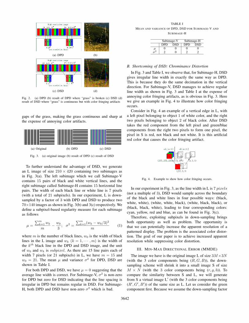
Fig. 2 shows the resultant images of two down-samplingpatterns: DPD and DSD. It is interesting to see that DSDcan potentially preserve more details than DPD thanks to theincrease in the number of individual reconstruction points. Aclose examination of Fig. 2(d) reveals that DSD fills in the
Fig. 2. (a) DPD (b) result of DPD where “grass” is broken (c) DSD (d)result of DSD where “grass” is continuous but with color fringing artifacts
gaps of the grass, making the grass continuous and sharp atthe expense of annoying color artifacts.
(a) Original (b) DPD (c) DSD
Fig. 3. (a) original image (b) result of DPD (c) result of DSD
To further understand the advantage of DSD, we generatean L image of size 210 × 420 containing two subimages asin Fig. 3(a). The left subimage which we call Subimage-Vcontains 15 pairs of black and white vertical lines, and theright subimage called Subimage-H contains 15 horizontal linepairs. The width of each black line or white line is 7 pixels(with a total of 21 subpixels). In our experiment, L is down-sampled by a factor of 3 with DPD and DSD to produce two70×140 images as shown in Fig. 3(b) and 3(c) respectively. Wedefine a subpixel-based regularity measure for each subimageas follows
µ =
∑mk=1 wk
m− w0
3; σ2 =
∑mk=1(wk − w0/3)
2
m(1)
where m is the number of black lines, w0 is the width of blacklines in the L image and wk (k = 1, · · · ,m) is the width ofthe kth black line in the DPD and DSD image, and the unitof w0 and wk is subpixel. As there are 15 line pairs each ofwidth 7 pixels (or 21 subpixels) in L, we have m = 15 andw0 = 21. The mean µ and variance σ2 for DPD, DSD areshown in Table I.
For both DPD and DSD, we have µ = 0 suggesting that theaverage line width is correct. For Subimage-V, σ2 is non-zerofor DPD but zero for DSD indicating that the line spacing isirregular in DPD but remains regular in DSD. For Subimage-H, both DPD and DSD have non-zero σ2 which is bad.
TABLE IMEAN AND VARIANCE OF DPD, DSD FOR SUBIMAGE-V AND
SUBIMAGE-H
Subimage-V Subimage-HDPD DSD DPD DSD
µ 0 0 0 0σ2 2 0 2 2
B. Shortcoming of DSD: Chrominance Distortion
In Fig. 3 and Table I, we observe that, for Subimage-H, DSDgives irregular line width in exactly the same way as DPD.This is because they do the same decimation in the verticaldirection. For Subimage-V, DSD manages to achieve regularline width as shown in Fig. 3 and Table I at the expense ofannoying color fringing artifacts, as is obvious in Fig. 3. Herewe give an example in Fig. 4 to illustrate how color fringingoccurs.
Consider in Fig. 4 an example of a vertical edge in L, witha left pixel belonging to object 1 of white color, and the righttwo pixels belonging to object 2 of black color. After DSDtakes the red component from the left pixel and green/bluecomponents from the right two pixels to form one pixel, thepixel in S is red, not black and not white. It is this artificialred color that causes the color fringing artifact.
Fig. 4. Example to show how color fringing occurs.
In our experiment in Fig. 3, as the line width in L is 7 pixels(not a multiple of 3), DSD would sample across the boundaryof the black and white lines in four possible ways: (black,white, white), (white, white, black), (white, black, black), or(black, black, white), leading to four corresponding colors:cyan, yellow, red and blue, as can be found in Fig. 3(c).
Therefore, exploiting subpixels in down-sampling bringsboth opportunity as well as problem. The opportunity isthat we can potentially increase the apparent resolution of apatterned display. The problem is the associated color distor-tion. The goal of our paper is to achieve increased apparentresolution while suppressing color distortion.
III. MIN-MAX DIRECTIONAL ERROR (MMDE)
The image we have is the original image L of size 3M×3N(with the 3 color components being (R,G,B)), the down-sampling scheme will shrink it into a small image S of sizeM × N (with the 3 color components being (r, g, b)). Tocompare the similarity between S and L, we will generatefrom S a virtual image L′ (with the 3 color components being(R′, G′, B′)) of the same size as L. Let us consider the greencomponent first. Because we assume the down-sampling factor
3642
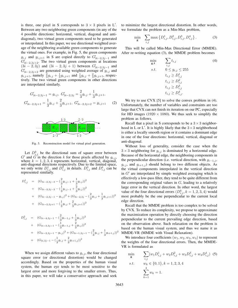
is three, one pixel in S corresponds to 3 × 3 pixels in L′.Between any two neighboring green components (in any of the4 possible directions: horizontal, vertical, diagonal and anti-diagonal), two virtual green components need to be generatedor interpolated. In this paper, we use directional weighted aver-age of the neighboring available green components to generatethe virtual ones. For example, in Fig. 5, the green componentsgi,j and gi,j+1 in S are copied directly to G′
3i−2,3j−1 andG′
3i−2,3j+2. The two virtual green components at locations(3i − 2, 3j) and (3i − 2, 3j + 1) between G′
3i−2,3j−1 andG′
3i−2,3j+2 are generated using weighted average of gi,j andgi,j+1, namely 2
3gi,j +13gi,j+1 and 1
3gi,j +23gi,j+1, respec-
tively. The two virtual green components in other directionsare interpolated similarly.
G′3i−2,3j−1 = gi,j , G′
3i−2,3j =2
3gi,j +
1
3gi,j+1,
G′3i−2,3j+1 =
1
3gi,j +
2
3gi,j+1, G′
3i−2,3j+2 = gi,j+1 (2)
Fig. 5. Reconstruction model for virtual pixel generation.
Let Dki,j be the directional sum of square error between
G′ and G in the direction k for those pixels affected by gi,j ,where k = 1, 2, 3, 4 represents horizontal, vertical, diagonal,anti-diagonal directions respectively. Due to the limited space,we only write D1
i,j and D2i,j in details. D3
i,j and D4i,j can be
represented similarly.
D1i,j = (G3i−2,3j−3 − (
2
3gi,j−1 +
1
3gi,j))
2
+ (G3i−2,3j−2 − (1
3gi,j−1 +
2
3gi,j))
2
+ (G3i−2,3j−1 − gi,j)2 + (G3i−2,3j − (
2
3gi,j +
1
3gi,j+1))
2
+ (G3i−2,3j+1 − (1
3gi,j +
2
3gi,j+1))
2
D2i,j = (G3i−4,3j−1 − (
2
3gi−1,j +
1
3gi,j))
2
+ (G3i−3,3j−1 − (1
3gi−1,j +
2
3gi,j))
2
+ (G3i−2,3j−1 − gi,j)2 + (G3i−1,3j−1 − (
2
3gi,j +
1
3gi+1,j))
2
+ (G3i,3j−1 − (1
3gi,j +
2
3gi+1,j))
2
When we assign different values to gi,j , the four directionalsquare error (or directional distortion) would be changedaccordingly. Based on the properties of the human visualsystem, the human eye tends to be most sensitive to thelargest error and more forgiving to the smaller errors. Thus,in this paper, we will take a conservative approach and seek
to minimize the largest directional distortion. In other words,we formulate the problem as a Min-Max problem,
ming
∑i,j
max{D1
i,j , D2i,j , D
3i,j , D
4i,j
}. (3)
This will be called Min-Max Directional Error (MMDE).After re-writing equation (3), the MMDE problem becomes
ming,t
∑i,j
ti,j (4)
s.t. 0 ≤ gi,j ≤ 255
ti,j ≥ D1i,j
ti,j ≥ D2i,j
ti,j ≥ D3i,j
ti,j ≥ D4i,j .
We try to use CVX [5] to solve the convex problem in (4).Unfortunately, the number of variables and constraints are toolarge that CVX can not finish its iteration on our PC, especiallyfor HD images (1920 × 1080). We thus seek to simplify theproblem as follows.
Recall that a pixel in S corresponds to be a 3× 3 neighbor-hood in L or L′. It is highly likely that the 3×3 neighborhoodis either a locally smooth region or it contains a dominant edgein one of the four directions: horizontal, vertical, diagonal oranti-diagonal.
Without loss of generality, consider the case when the3× 3 neighboring for gi,j is dominated by a horizontal edge.Because of the horizontal edge, the neighboring components inthe perpendicular direction (i.e. vertical direction, with gi−1,j ,gi,j , and gi+1,j) should belong to two different objects. Asthe virtual components interpolated in the vertical directionin G′ are interpolated by simple weighted averaging which iseffectively a low-pass filter, they tend to be quite different fromthe corresponding original values in G, leading to a relativelylarge error in the vertical direction. In other word, the largestvalue of the four directional errors (Dk
i,j , k = 1, 2, 3, 4) wouldmost probably be the one perpendicular to the current localedge direction.
Recall that the MMDE problem is too complex to be solvedby CVX. To reduce its complexity, we propose to approximatethe maximization operation by directly choosing the directionperpendicular to the current prevailing edge direction, basedon the observation above. Such relaxation on the problem isbased on the human visual system, and thus we name it asMMDE-VR (MMDE with Visual Relaxation).
We introduce four coefficients (w1, w2, w3, w4) to representthe weights of the four directional errors. Then, the MMDE-VR is formulated as
ming
∑i,j
(w1D1i,j + w2D
2i,j + w3D
3i,j + w4D
4i,j) (5)
s.t. wk ∈ {0, 1}, k = 1, 2, 3, 44∑
k=1
wk = 1.
3643
where the values of (w1, w2, w3, w4) are determined adap-tively by local edge directions,
(w1, w2, w3, w4) =
(1, 0, 0, 0), if Dir(gi,j) = Vertical(0, 1, 0, 0), if Dir(gi,j) = Horizontal(0, 0, 1, 0), if Dir(gi,j) = Anti-Diagonal(0, 0, 0, 1), if Dir(gi,j) = Diagonal
and Dir(gi,j) is a function used to determine the local edgedirection of gi,j . We calculate the directional gradient sum∆k
i,j for the four directions, k = 1, 2, 3, 4, in the 3 × 3neighborhood in Y corresponding to gi,j (note that we areusing Y [6] instead of G),
Simulation results below give a subjective measure for thevisual quality, including luminance sharpness and chrominancedistortion.
Fig. 6(a) shows that DPD causes severe aliasing artifactsand destroys shape information in regions with high spatialfrequency. PDAF does smooth the result, but it causes blurring,as shown in Fig. 6(b). The result of DSD is much clearer andsharper than that of PDAF. But it maintains the sharpness atthe expense of color fringing artifacts, as verified in Fig. 6(c).From Fig. 6(d), we can find that our proposed method notonly effectively reduces color fringing artifacts but also givessharper and clearer results than conventional down-samplingmethods (especially the regions inside red circles). Similarconclusions could be obtained from Fig. 7.
Note that showing the results in printed form may haveproblem, since subpixel rendering depends heavily upon thephysical proximity of adjacent subpixels such as (RGB) or(BGR). It is also affected by the distance between the observerand LCD screen. Closer distance results in chromatic distor-tion, and further distance decreases the luminance resolutionadvantage until it cannot be seen at all.
V. CONCLUSION
In this paper, we propose a new method via Min-Maxdirectional error (MMDE) for subpixel-based down-sampling.Since MMDE is computational intensive to be directly solved,we then make some appropriate approximation to the problemwhich can effectively reduce the computational complexity.Experimental results show that the proposed method canprovide sharper and clearer images than the conventional pixel-based down-sampling method (PDAF).
(a) (b)
(c) (d)
Fig. 6. (a): DPD (b): PDAF (c): DSD (d): MMDE-VR
(a) (b)
(c) (d)
Fig. 7. (a): DPD (b): PDAF (c): DSD (d): MMDE-VR
VI. ACKNOWLEDGMENT
This work has been supported in part by the Research GrantsCouncil (RGC) of the Hong Kong Special AdministrativeRegion, China. (GRF Project no. 610109).
REFERENCES
[1] S. Gibson, “ Sub-Pixel Font Rendering Technology”, fromhttp://www.grc.com/cleartype.htm.
[2] C. Betrisey, J. F. Blinn, et. al., “Displaced Filtering for Patterned Dis-plays”, SID Digest of Technical Papers, Vol. 31, pp. 296-299, 2000.
[3] J. C. Platt, “Optimal Filtering for Patterned Displays”, IEEE SignalProcessing Letter, Vol. 7, No. 7, pp. 179-181, July 2000.
[4] S. J. Daly, et. al., “Methods and Systems for Improving Display Resolu-tion in Images using Sub-pixel Sampling and Visual Error Filtering”, USPatent, US 6,608,632 B2, Aug. 2003.
[5] Michael Grant, Stephen Boyd, Yinyu Ye, cvx Users’ Guide, Stanford,Sept. 2008.