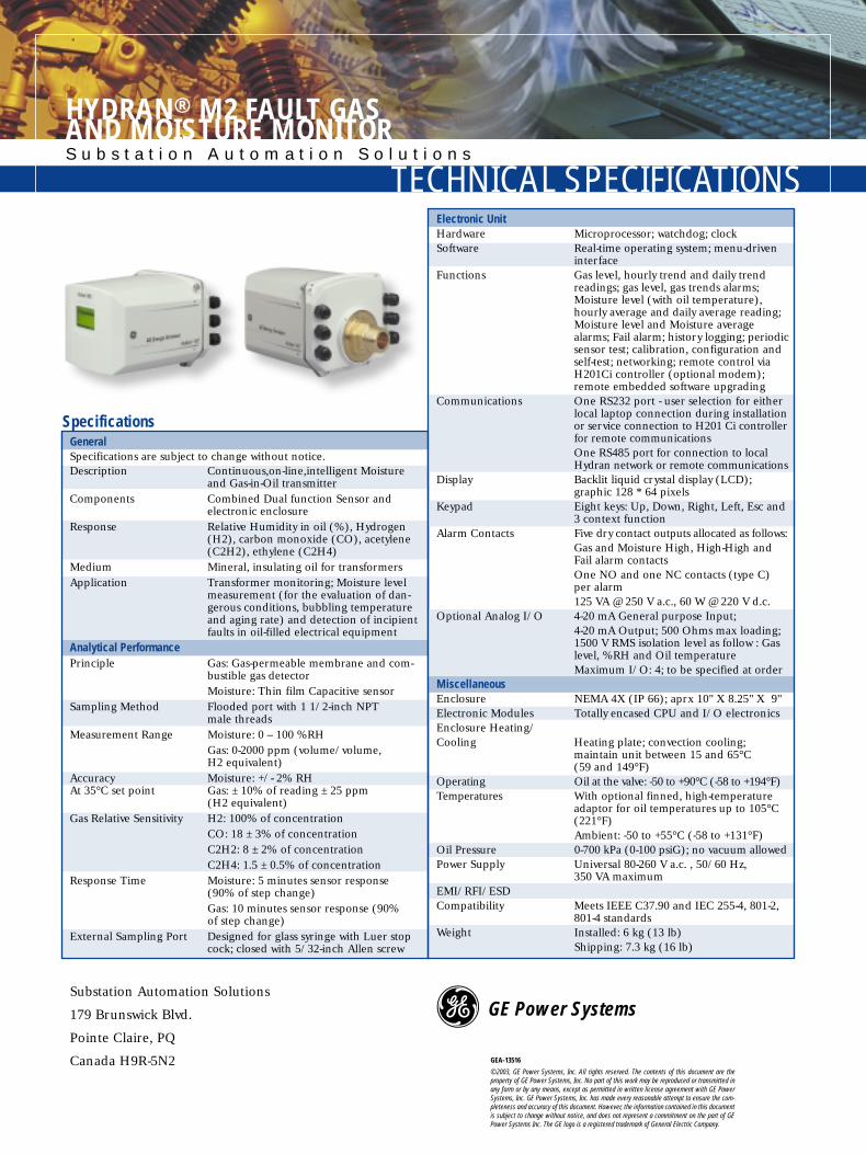
Medium Mineral, insulating oil for transformersApplication Transformer monitoring; Moisture level
measurement (for the evaluation of dan-gerous conditions, bubbling temperatureand aging rate) and detection of incipientfaults in oil-filled electrical equipment
Analytical PerformancePrinciple Gas: Gas-permeable membrane and com-
bustible gas detectorMoisture: Thin film Capacitive sensor
Sampling Method Flooded port with 1 1/2-inch NPT male threads
interfaceFunctions Gas level, hourly trend and daily trend
readings; gas level, gas trends alarms; Moisture level (with oil temperature),hourly average and daily average reading;Moisture level and Moisture averagealarms; Fail alarm; history logging; periodicsensor test; calibration, configuration andself-test; networking; remote control viaH201Ci controller (optional modem);remote embedded software upgrading
Communications One RS232 port - user selection for eitherlocal laptop connection during installationor service connection to H201 Ci controllerfor remote communicationsOne RS485 port for connection to localHydran network or remote communications
Alarm Contacts Five dry contact outputs allocated as follows:Gas and Moisture High, High-High andFail alarm contactsOne NO and one NC contacts (type C)per alarm125 VA @ 250 V a.c., 60 W @ 220 V d.c.
Optional Analog I/O 4-20 mA General purpose Input;4-20 mA Output; 500 Ohms max loading;1500 V RMS isolation level as follow : Gaslevel, %RH and Oil temperatureMaximum I/O: 4; to be specified at order
MiscellaneousEnclosure NEMA 4X (IP 66); aprx 10" X 8.25" X 9"Electronic Modules Totally encased CPU and I/O electronicsEnclosure Heating/Cooling Heating plate; convection cooling;
maintain unit between 15 and 65°C (59 and 149°F)
Operating Oil at the valve: -50 to +90°C (-58 to +194°F)Temperatures With optional finned, high-temperature
adaptor for oil temperatures up to 105°C(221°F)Ambient: -50 to +55°C (-58 to +131°F)
Oil Pressure 0-700 kPa (0-100 psiG); no vacuum allowedPower Supply Universal 80-260 V a.c. , 50/60 Hz,
350 VA maximumEMI/RFI/ESDCompatibility Meets IEEE C37.90 and IEC 255-4, 801-2,
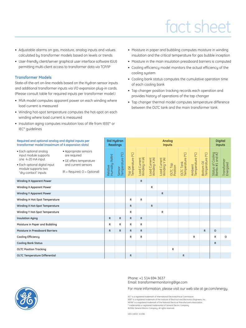
Required and optional analog and digital inputs per transformer model (maximum of 4 expansion slots)
Std HydranReadings
Analog Inputs
Digital Inputs
Winding H Apparent Power R
Winding X Apparent Power R
Winding Y Apparent Power R
Winding H Hot-Spot Temperature R R
Winding X Hot-Spot Temperature R R
Winding Y Hot-Spot Temperature R R
Insulation Aging R R R R
Moisture in Paper and Bubbling R R R R
Moisture in Pressboard Barriers R R R R R O
Cooling Efficiency R R R R O
Cooling Bank Status R
OLTC Position Tracking R
OLTC Temperature Differential R R
Rela
tive
Hum
idity
(%RH
)
Sens
or
Tem
pera
ture
(ºC
)
Top
Oil
Tem
pera
ture
(ºC
)
Load
Cur
rent
W
indi
ng H
(A)
Load
Cur
rent
W
indi
ng X
(A)
Load
Cur
rent
W
indi
ng Y
(A)
OLT
C T
ap
Posi
tion
OLT
C T
ank
Tem
pera
ture
(ºC
)
Ambi
ent
Tem
pera
ture
(ºC
)
Bott
om O
il Te
mpe
ratu
re (º
C)
Stat
us o
f Coo
ling
Bank
s #
1 an
d #
2
Tran
sfor
mer
En
ergi
zed
• Each optional analog input module supports one 4-20 mA input
• Each optional digital inputmodule supports two “dry-contact” inputs
• Appropriate sensors are required
• GE offers temperature and current sensors
(R = Required; O = Optional)
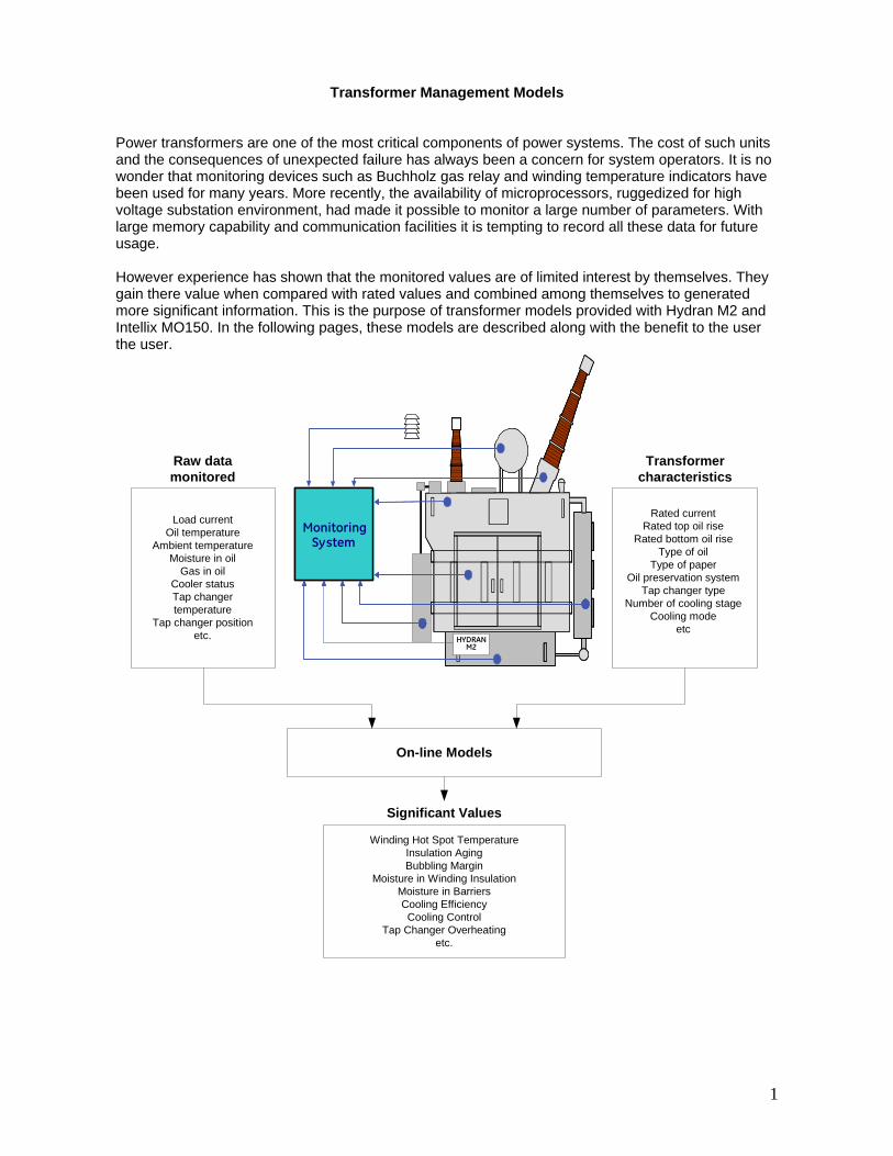
Transformer Management Models
Power transformers are one of the most critical components of power systems. The cost of such units and the consequences of unexpected failure has always been a concern for system operators. It is no wonder that monitoring devices such as Buchholz gas relay and winding temperature indicators have been used for many years. More recently, the availability of microprocessors, ruggedized for high voltage substation environment, had made it possible to monitor a large number of parameters. With large memory capability and communication facilities it is tempting to record all these data for future usage. However experience has shown that the monitored values are of limited interest by themselves. They gain there value when compared with rated values and combined among themselves to generated more significant information. This is the purpose of transformer models provided with Hydran M2 and Intellix MO150. In the following pages, these models are described along with the benefit to the user
the user.
Load currentOil temperature
Ambient temperatureMoisture in oil
Gas in oilCooler statusTap changertemperature
Tap changer positionetc.
Raw datamonitored
Rated currentRated top oil rise
Rated bottom oil riseType of oil
Type of paperOil preservation system
Tap changer typeNumber of cooling stage
Cooling modeetc
Transformercharacteristics
On-line Models
Winding Hot Spot TemperatureInsulation AgingBubbling Margin
Moisture in Winding InsulationMoisture in BarriersCooling EfficiencyCooling Control
Tap Changer Overheatingetc.
Significant Values
System
HYDRAN
SystemMonitoringSystem
M2HYDRAN
1
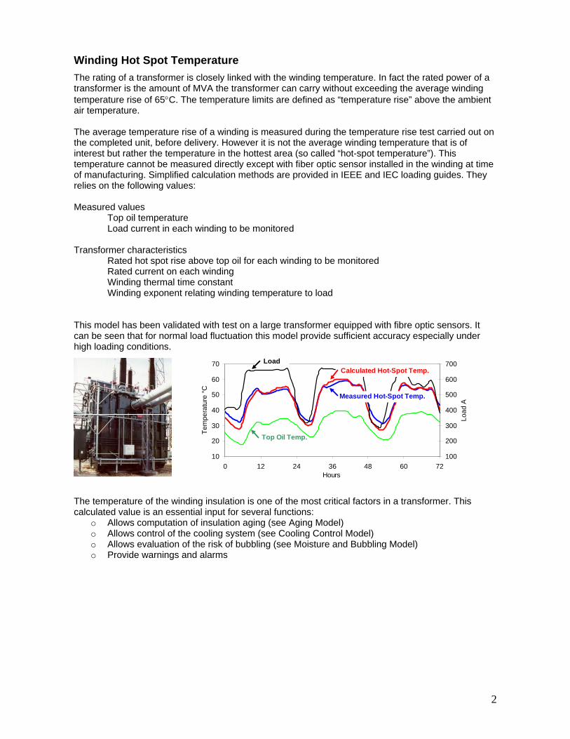
Winding Hot Spot Temperature The rating of a transformer is closely linked with the winding temperature. In fact the rated power of a transformer is the amount of MVA the transformer can carry without exceeding the average winding temperature rise of 65°C. The temperature limits are defined as “temperature rise” above the ambient air temperature. The average temperature rise of a winding is measured during the temperature rise test carried out on the completed unit, before delivery. However it is not the average winding temperature that is of interest but rather the temperature in the hottest area (so called “hot-spot temperature”). This temperature cannot be measured directly except with fiber optic sensor installed in the winding at time of manufacturing. Simplified calculation methods are provided in IEEE and IEC loading guides. They relies on the following values: Measured values Top oil temperature
Load current in each winding to be monitored
Transformer characteristics Rated hot spot rise above top oil for each winding to be monitored
Rated current on each winding Winding thermal time constant
Winding exponent relating winding temperature to load
This model has been validated with test on a large transformer equipped with fibre optic sensors. It can be seen that for normal load fluctuation this model provide sufficient accuracy especially under
high loading conditions.
he temperature of the winding insulation is one of the most critical factors in a transformer. This
odel) odel)
g Model)
10
20
30
40
50
60
70
0 12 24 36 48 60 72Hours
Tem
pera
ture
°C
100
200
300
400
500
600
700
Load
A
Load
Top Oil Temp.
Calculated Hot-Spot Temp.
Measured Hot-Spot Temp.
Tcalculated value is an essential input for several functions:
o Allows computation of insulation aging (see Aging Mo Allows control of the cooling system (see Cooling Control Mo Allows evaluation of the risk of bubbling (see Moisture and Bubblino Provide warnings and alarms
2
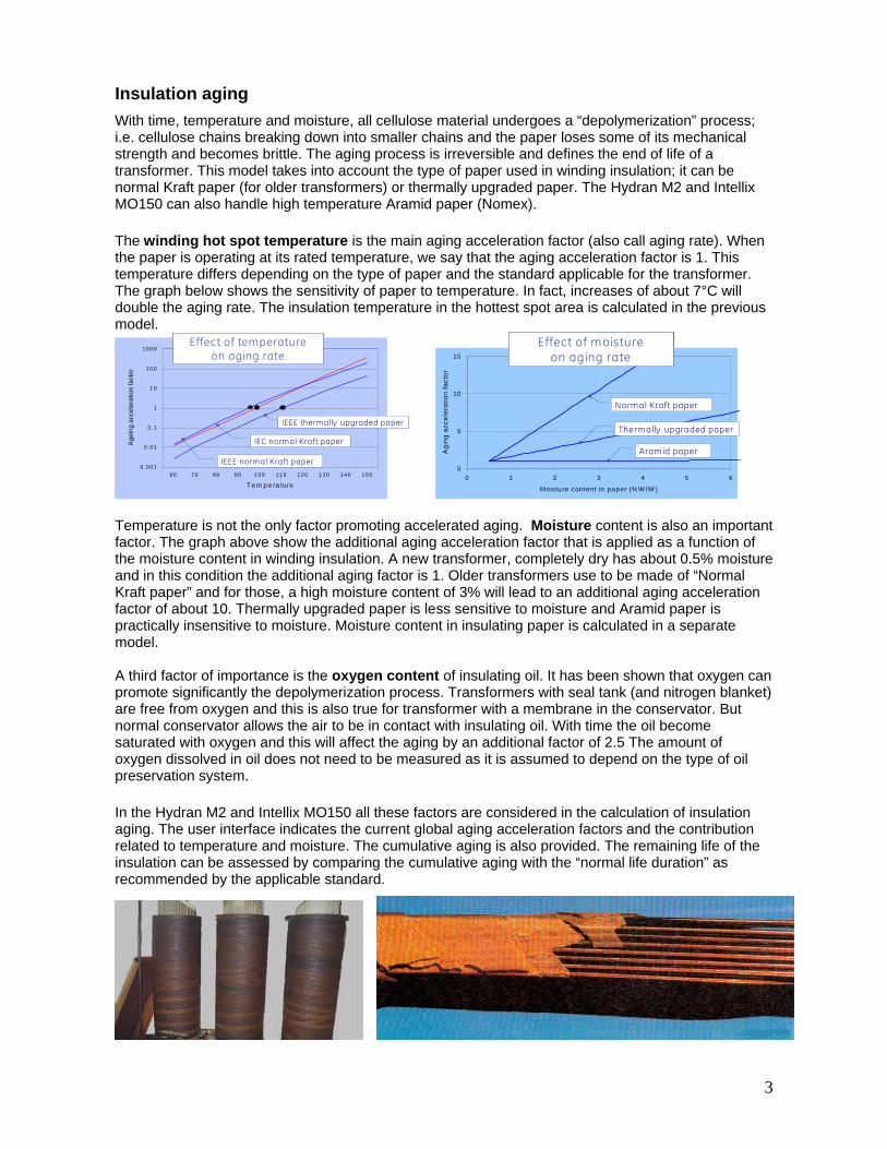
Insulation aging With time, temperature and moisture, all cellulose material undergoes a “depolymerization” process; i.e. cellulose chains breaking down into smaller chains and the paper loses some of its mechanical strength and becomes brittle. The aging process is irreversible and defines the end of life of a transformer. This model takes into account the type of paper used in winding insulation; it can be normal Kraft paper (for older transformers) or thermally upgraded paper. The Hydran M2 and Intellix MO150 can also handle high temperature Aramid paper (Nomex). The winding hot spot temperature is the main aging acceleration factor (also call aging rate). When the paper is operating at its rated temperature, we say that the aging acceleration factor is 1. This temperature differs depending on the type of paper and the standard applicable for the transformer. The graph below shows the sensitivity of paper to temperature. In fact, increases of about 7°C will double the aging rate. The insulation temperature in the hottest spot area is calculated in the previous
model.
emperature is not the only factor promoting accelerated aging. Moisture content is also an important
n
e
third factor of importance is the oxygen content of insulating oil. It has been shown that oxygen can
oil
the Hydran M2 and Intellix MO150 all these factors are considered in the calculation of insulation
Tfactor. The graph above show the additional aging acceleration factor that is applied as a function of the moisture content in winding insulation. A new transformer, completely dry has about 0.5% moisture and in this condition the additional aging factor is 1. Older transformers use to be made of “Normal Kraft paper” and for those, a high moisture content of 3% will lead to an additional aging acceleratiofactor of about 10. Thermally upgraded paper is less sensitive to moisture and Aramid paper is practically insensitive to moisture. Moisture content in insulating paper is calculated in a separatmodel. Apromote significantly the depolymerization process. Transformers with seal tank (and nitrogen blanket) are free from oxygen and this is also true for transformer with a membrane in the conservator. But normal conservator allows the air to be in contact with insulating oil. With time the oil become saturated with oxygen and this will affect the aging by an additional factor of 2.5 The amount ooxygen dissolved in oil does not need to be measured as it is assumed to depend on the type ofpreservation system.
f
Inaging. The user interface indicates the current global aging acceleration factors and the contribution related to temperature and moisture. The cumulative aging is also provided. The remaining life of the insulation can be assessed by comparing the cumulative aging with the “normal life duration” as recommended by the applicable standard.
3
4
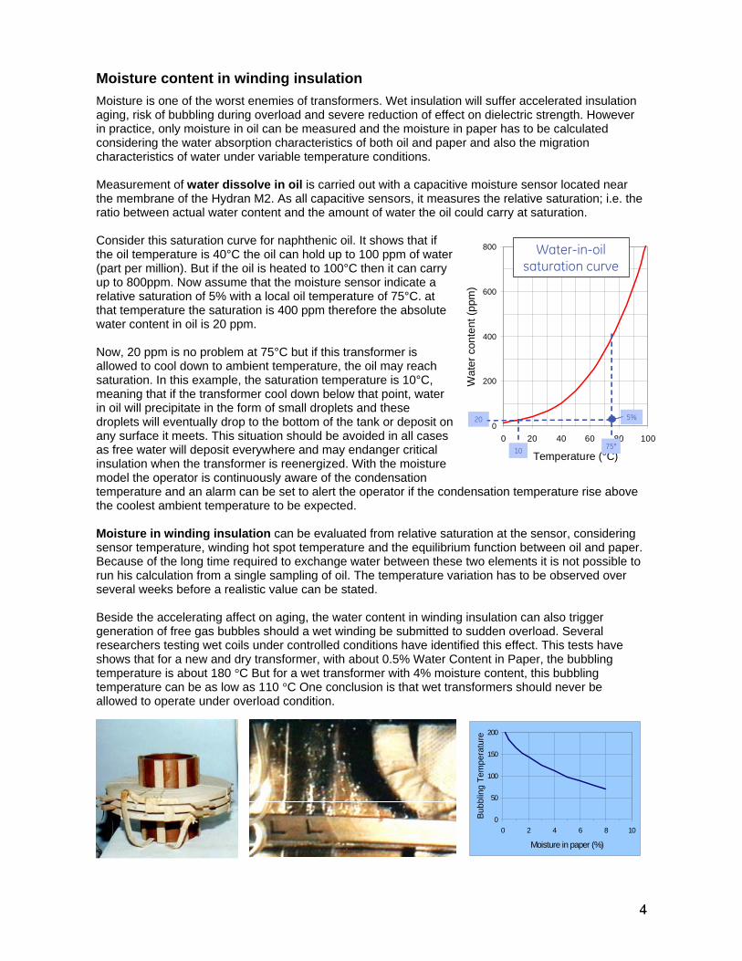
oisture content in winding insulation Moisture is one of the worst enemies of transformers. Wet insulation will suffer accelerated insulation aging, risk of bubbling during overload and severe reduction of effect on dielectric strength. However in practice, only moisture in oil can be measured and the moisture in paper has to be calculated considering the water absorption characteristics of both oil and paper and also the migration characteristics of water under variable temperature conditions. Measurement of water dissolve in oil is carried out with a capacitive moisture sensor located near the membrane of the Hydran M2. As all capacitive sensors, it measures the relative saturation; i.e. the ratio between actual water content and the amount of water the oil could carry at saturation. Consider this saturation curve for naphthenic oil. It shows that if the oil temperature is 40°C the oil can hold up to 100 ppm of water (part per million). But if the oil is heated to 100°C then it can carry up to 800ppm. Now assume that the moisture sensor indicate a relative saturation of 5% with a local oil temperature of 75°C. at that temperature the saturation is 400 ppm therefore the absolute water content in oil is 20 ppm. Now, 20 ppm is no problem at 75°C but if this transformer is allowed to cool down to ambient temperature, the oil may reach saturation. In this example, the saturation temperature is 10°C, meaning that if the transformer cool down below that point, water in oil will precipitate in the form of small droplets and these droplets will eventually drop to the bottom of the tank or deposit on any surface it meets. This situation should be avoided in all cases as free water will deposit everywhere and may endanger critical insulation when the transformer is reenergized. With the moisture model the operator is continuously aware of the condensation temperature and an alarm can be set to alert the operator if the condensation temperature rise above the coolest ambient temperature to be expected. Moisture in winding insulation can be evaluated from relative saturation at the sensor, considering sensor temperature, winding hot spot temperature and the equilibrium function between oil and paper. Because of the long time required to exchange water between these two elements it is not possible to run his calculation from a single sampling of oil. The temperature variation has to be observed over several weeks before a realistic value can be stated. Beside the accelerating affect on aging, the water content in winding insulation can also trigger
M
0
200
400
600
800
0 20 40 60 80 100
Temperature (°C)W
ater
con
tent
(ppm
)
Water-in-oilsaturation curve
75°10
20 5%0
200
400
600
800
0 20 40 60 80 100
Temperature (°C)W
ater
con
tent
(ppm
)
Water-in-oilsaturation curve
75°75°1010
20 5%20 5%
generation of free gas bubbles should a wet winding be submitted to sudden overload. Several researchers testing wet coils under controlled conditions have identified this effect. This tests have shows that for a new and dry transformer, with about 0.5% Water Content in Paper, the bubbling temperature is about 180 °C But for a wet transformer with 4% moisture content, this bubbling temperature can be as low as 110 °C One conclusion is that wet transformers should never be allowed to operate under overload condition.
0
50
100
150
200
0 2 4 6 8 10
Moisture in paper (%)
Bubb
ling
Tem
pera
ture
4
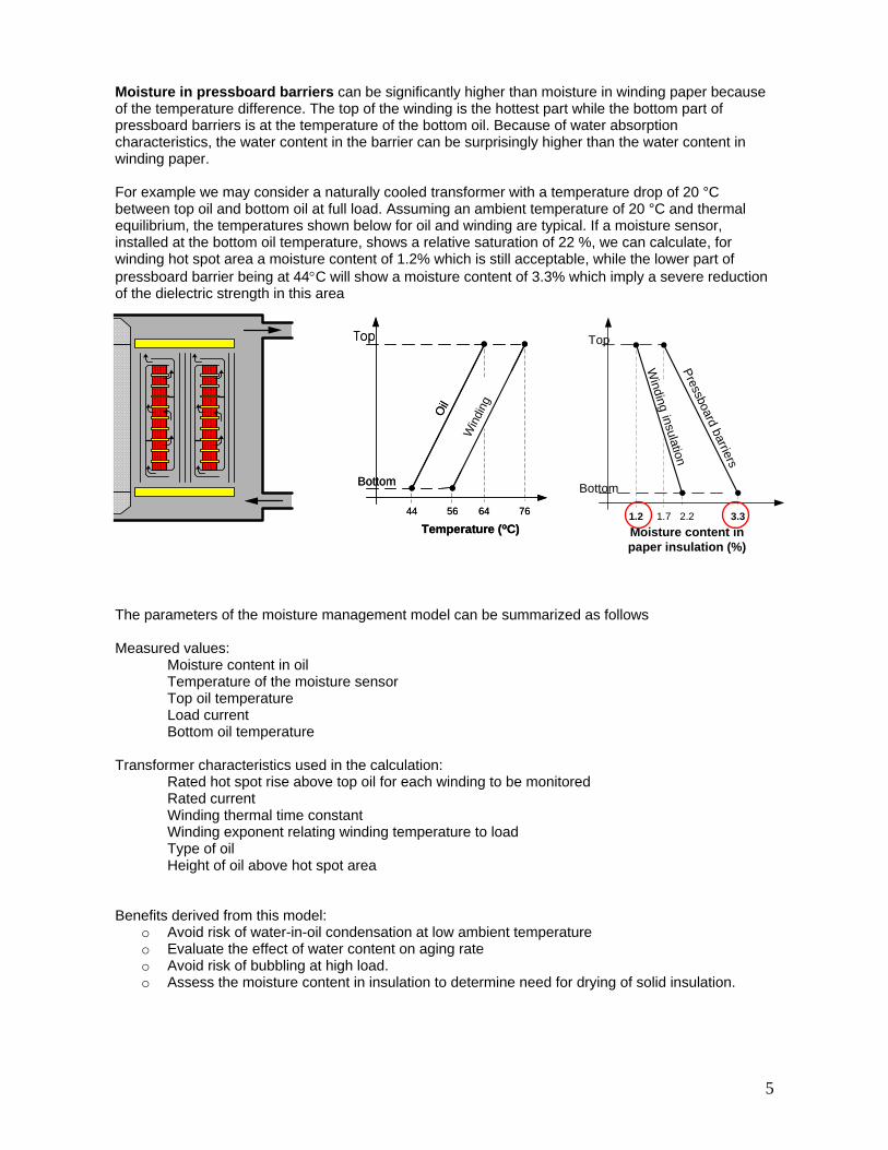
Moisture in pressboard barriers can be significantly higher than moisture in winding paper because
th a temperature drop of 20 °C
t of 3% which imply a severe reduction
el can be summarized as follows
Height of oil above hot spot area
Benefits derived from this model: o Avoid risk of water-in-oil condensation at low ambient temperature o Evaluate the effect of water content on aging rate o Avoid risk of bubbling at high load. o Assess the moisture content in insulation to determine need for drying of solid insulation.
of the temperature difference. The top of the winding is the hottest part while the bottom part of pressboard barriers is at the temperature of the bottom oil. Because of water absorption characteristics, the water content in the barrier can be surprisingly higher than the water content in winding paper. For example we may consider a naturally cooled transformer wibetween top oil and bottom oil at full load. Assuming an ambient temperature of 20 °C and thermal equilibrium, the temperatures shown below for oil and winding are typical. If a moisture sensor, installed at the bottom oil temperature, shows a relative saturation of 22 %, we can calculate, for winding hot spot area a moisture content of 1.2% which is still acceptable, while the lower parpressboard barrier being at 44°C will show a moisture content of 3.of the dielectric strength in this area
Win
di
44 6456 76
Temperature (oC)
ngOil
Bottom
he parameters of the moisture management modT Measured values: Moisture content in oil
Temperature of the moisture sensor Top oil temperature Load current Bottom oil temperature
Transformer characteristics used in the calculation: Rated hot spot rise above top oil for each winding to be monitored
Rated current Winding thermal time constant
Winding exponent relating winding temperature to load Type of oil
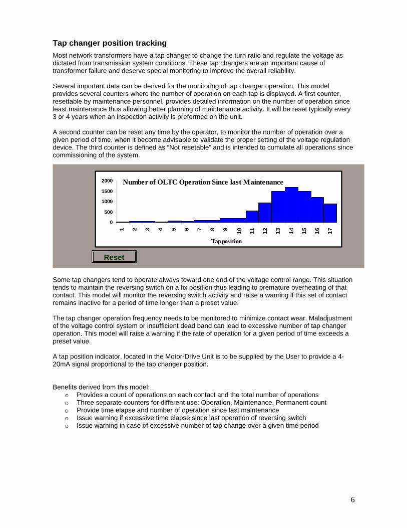
Tap changer position tracking Most network transformers have a tap changer to change the turn ratio and regulate the voltagedictated from transmission system conditions. These tap changers are an important cause of transformer failure and deserve special monitoring to improve the overall reliability.
as
ery
visable to validate the proper setting of the voltage regulation device. The third counter is defined as “Not resetable” and is intended to cumulate all operations since commissioning of the system.
ge. This situation ating of that
l will monitor the reversing switch activity and raise a warning if this set of contact time longer than a preset value.
The tap nitored to minimize contact wear. Maladjustment of the v or insufficient dead band can lead to excessive number of tap changer operatio warning if the rate of operation for a given period of time exceeds a preset v
the User to provide a 4-0mA s
Benefitso each contact and the total number of operations o ent use: Operation, Maintenance, Permanent count o rovide time elapse and number of operation since last maintenance
time elapse since last operation of reversing switch od
Several important data can be derived for the monitoring of tap changer operation. This model provides several counters where the number of operation on each tap is displayed. A first counter, resettable by maintenance personnel, provides detailed information on the number of operation since least maintenance thus allowing better planning of maintenance activity. It will be reset typically ev3 or 4 years when an inspection activity is preformed on the unit. A second counter can be reset any time by the operator, to monitor the number of operation over a given period of time, when it become ad
0
500
1000
1500
2000
1 2 3 4 5 6 7 8 9 10 11 12 13 14 15 16 17
Tap position
Number of OLTC Operation Since last Maintenance
Reset
Some tap changers tend to operate always toward one end of the voltage control ran
nds to maintain the reversing switch on a fix position thus leading to premature overhetecontact. This mode
mainsre inactive for a period of
changer operation fresystem
quency needs to be mooltage control n. This model will raise alue. a
A tap position indicator, located in the Motor-Drive Unit is to be supplied by 2 l to the tap changer position. ignal proportiona
derived from this model: Provides a count of operations on
hree separate counters for differTP
o Issue warning if excessiveo Issue warning in case of excessive number of tap change over a given time peri
6
Tap changer temperature
r progressive misalignment or loosening of contacts.
this model, the temperature of the tap changer
ed if the temperature of the tap changer compartment starts to rise significantly.
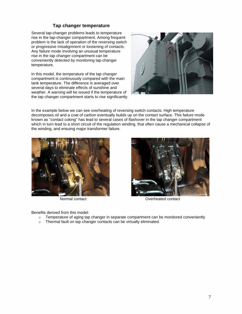
reversindecomposes oil and a coat of carbon eventually buildknown as "contact coking" has lead to several cases which in turn lead to a short circuit of the regulation withe winding, and ensuing major transformer failure.
compartment can be monitored conveniently o Thermal fault on tap changer contacts can be virtually eliminated.
Several tap-changer problems leads to temperature rise in the tap-changer compartment. Among frequent problem is the lack of operation of the reversing switch oAny failure mode involving an unusual temperature rise in the tap changer compartment can be conveniently detected by monitoring tap-changer temperature. Incompartment is continuously compared with the main tank temperature. The difference is averaged over several days to eliminate effects of sunshine and weather. A warning will be issu
In the example below we can see overheating of g switch contacts. High temperature s up on the contact surface. This failure mode of flashover in the tap changer compartment nding, that often cause a mechanical collapse of
Normal contact Overheated contact Benefits derived from this model:
o Temperature of aging tap changer in separate
7
Cooling S trol nt of a transformer. Although the transformer is
ed to ensure that full cooling capacity is dition. Several aspect of the cooling system er.
itored using the digital input available on the Hydran tellix MO150. These monitoring systems will provide the current cooling status and the
umulative operating time for each cooling bank. The cumulative duty on each cooling bank is useful .
formation:
k
.
. It would be unwise to wait until an emergency ad occurs to discover that the cooling is not in full running order.
This model computes continuously the temperature that the top oil should have, considering load, ambient temperature, cooling mode, oil time constant and other transformer characteristics. This theoretical top oil temperature is then compares to the measured value of top oil temperature. The difference is weighted and averaged over time to generate a cooling efficiency index. When this value exceeds a configured threshold, a warning is issued. This model requires an ambient temperature sensor. It provides the following benefit:
o Raise a warning if the transformer is running warmer than it should. Cooling ControlThis model is available on Intellix MO150 only. It complements the control features provided by the transformer man
mperature, it i lier start hen a sudden overload occurs. Moreover the load current rating can be adjusted to follow the
erature and altitude of the site where the transformer is installed.
Forof coolin tween fan motor maintenance. A time delay function is available to avoid the two cooling banks from starting at the same time. Moreover, a cooler exercising routine can be used to run the units for a few minutes every week. Proper operation of the cooling system is also monitored with continuous measurement of pump motor and fan motor current draw by each cooling bank. A malfunction of some elements is to be suspected when the current is significantly below or significantly above the normal value. This model requires cooling bank current sensors. It provides the following benefits:
o Intelligent cooling control based on, top oil temperature, winding temperature, or load current. o Cost saving on fan and pumps motor maintenance with duty sharing function. o Detection of pumps and fans malfunction.
ystem Monitoring and ConTransformer cooling system is an essential componeseldom operating at rated load, the system operator neavailable all the time, in case of unexpected loading concan be monitored to improve availability of the transform Cooling Bank Status The status of individual cooling banks can be monM2 and the Incto plan maintenance activity on the cooling system User interface provides continuously the following in
o Current status of each cooling bank o Cumulative operating time on each cooling ban
Cooling Efficiency Effectiveness of the cooling system is demonstrated as part of the temperature rise test on new unitsIn service, the cooling capacity can loss some of it performance due to fan failure or clogging of coolers by pollen or dust. Although the actual load might be lower than rated value, it is advisable to check that the cooling system is working as expectedlo
ufacturer. Beside the traditional control by top oil temperature and winding s now possible to link cooler initiation to the load current thus providing an earte
wseasonal variation of ambient temp
transformers with two cooling banks, a duty sharing function can be inig banks to equalize the wear on bearings and extend the period be
tiated to alternate the usage
8
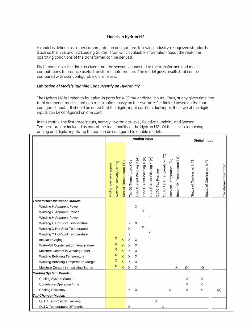
Models in Hydran M2 A model is defined as a specific computation or algorithm, following industry-recognized standards (such as the IEEE and IEC Loading Guides), from which valuable information about the real-time operating conditions of the transformer can be derived. Each model uses the data received from the sensors connected to the transformer, and makes computations to produce useful transformer information. The model gives results that can be compared with user configurable alarm levels.
Limitation of Models Running Concurrently on Hydran M2
The Hydran M2 is limited to four plug-in ports for 4-20 mA or digital inputs. Thus, at any given time, the total number of models that can run simultaneously on the Hydran M2 is limited based on the four configured inputs. It should be noted that the digital input card is a dual input, thus two of the digital inputs can be configured on one card. In this matrix, the first three inputs, namely Hydran gas level, Relative Humidity, and Sensor Temperature are included as part of the functionality of the Hydran M2. Of the eleven remaining analog and digital inputs, up to four can be configured to enable models.
B Sparling GE Energy Page 1 20/10/2006 HYDRAN M2 Model Summary Description
Analog Input Digital Input
Hyd
ran
gas
leve
l (pp
m)
Rel
ativ
e H
umid
ity (%
RH
)
Sen
sor T
empe
ratu
re (o C
)
Top
Oil
Tem
pera
ture
(o C)
Load
Cur
rent
Win
ding
H (A
)
Load
Cur
rent
Win
ding
X (A
)
Load
Cur
rent
Win
ding
Y (A
)
OLT
C T
ap P
ositi
on
OLT
C T
ank
Tem
pera
ture
(o C)
Am
bien
t Tem
pera
ture
(o C)
Bot
tom
Oil
Tem
pera
ture
(o C)
Sta
tus
of C
oolin
g ba
nk #
1
Sta
tus
of C
oolin
g ba
nk #
2
Tran
sfor
mer
Ene
rgiz
ed
Transformer Insulation Models
Winding H Apparent Power X
Winding H Apparent Power X
Winding H Apparent Power X
Winding H Hot-Spot Temperature X X
Winding X Hot-Spot Temperature X X
Winding Y Hot-Spot Temperature X X
Insulation Aging X X X X
Water-Oil Condensation Temperature X X X X
Moisture Content in Winding Paper X X X X
Winding Bubbling Temperature X X X X
Winding Bubbling Temperature Margin X X X X
Moisture Content in Insulating Barrier X X X X X (X) (X)
Cooling System Models
Cooling System Status X X
Cumulative Operation Time X X
Cooling Efficiency X X X X X (X)
Tap Changer Models
OLTC Tap Position Tracking X
OLTC Temperature Differential X X
Assigning Inputs
The models are dynamically enabled based on the inputs configured. The inputs to activate the models can be selected from a predefined list during input configuration. The list of analog inputs include:
• Top Oil Temperature • OLTC Tank Temperature • Tap Position • Winding H Current • Winding X Current • Winding Y Current • Ambient Temperature • Bottom Oil Temperature • User Defined
The list of digital inputs include:
• Feedback status of cooling bank #1 • Feedback status of cooling bank #2 • Transformer Energized status • User Defined
Input Alarms: The inputs top oil, bottom oil and ambient temperature all have input fault alarms that can be enabled or disabled. A lost input connection will produce N/A values for the inputs as well as the corresponding models, thus the input fault alarms will alert the user that the input signal is unavailable.
Available Models Apparent Power: The primary function of this model is to continuously monitor the load carried by the transformer in MVA (Mega Volt-Amperes). The Apparent Power can be computed on the Primary, Secondary, and Tertiary windings, depending on the input configuration. The historic maximum MVA value is retained with a timestamp and can be reset by the user. The current signal is a mandatory input, whereas the voltage signal is configured as a fixed value. Since voltage variations occurring in service and tap changer operations are not taken into consideration, the MVA is an approximate reading, and used only for display.
Required Inputs:
• Load current on Winding H • Load current on Winding X (optional) • Load current on Winding Y (optional)
B Sparling GE Energy Page 2 20/10/2006 HYDRAN M2 Model Summary Description
Outputs:
• Winding H MVA • Historic Maximum Value of load on H winding with a time stamp. Load is expressed in Per Unit
of rated current (P.U.) This value is resettable by the user o
• Winding X MVA (if load current X is configured as an input) • Historic Maximum Value of load on X winding with a time stamp. Load is expressed in Per Unit
of rated current (P.U.) This value is resettable by the user o
• Winding Y MVA (if load current Y is configured as an input) • Historic Maximum Value of load on Y winding with a time stamp. Load is expressed in Per Unit
of rated current (P.U.) This value is resettable by the user
Winding Hot-Spot Temperature Model: The rating of a transformer is closely linked with the winding temperature as it governs the insulation-aging rate and bubbling release threshold. The winding temperature can also raise alarm if excessive values are taking place. In the industry standards, the winding temperature limits is defined as a temperature rise above the ambient air temperature. The cooling system is design to insure that at full load, the average winding temperature rise do not exceed the value accepted in the industry (usually 65°C). However it is not the average winding temperature that is of most interest but rather the temperature in the hottest area (so called “hot-spot temperature”). This temperature cannot be measured directly as it is not possible to insert thermocouples in a winding that is to be put in service. It is possible to use fiber optic temperature sensors that do not interfere with dielectric strength but this procedure is costly and is usually limited to the validation of the manufacturer calculation methods. Therefore the traditional method was to use a Winding Temperature Indicator to fulfill that function. Using the equations provided in IEEE and IEC loading guides, a more accurate and reliable evaluation of the hot spot temperature can be provided. A key value is the temperature difference between winding hot spot and top oil at rated condition. The transformer manufacturer normally provides this value after suitable validation of their calculation method. In the Winding Hot Spot model, this rated value is corrected to account for actual load current and winding thermal time constant. The calculated hot spot temperature rise is then added to the measured top oil temperature to provide the actual winding hottest spot temperature. The winding hot-spot temperature is calculated separately for each winding. The highest value of Winding Hot-Spot Temperature is identified and used to raise alarm signal on the transformer and also to control stage 2 and stage 3 of the cooling system. The hottest winding might not always be the same, depending on the load on the tertiary winding and on the position of the tap changer. For Autotransformers the Winding Hot Spot Temperature is calculated for Series Winding (H), Common Winding (C) and Tertiary Winding (Y). The current in the common winding is calculated by subtracting secondary load current minus primary load current
Required Inputs:
• Top Oil Temperature • Load current on Winding H
B Sparling GE Energy Page 3 20/10/2006 HYDRAN M2 Model Summary Description
• Load current on Winding X (optional) • Load current on Winding Y (optional)
Outputs:
• Winding Hot-Spot Temperature in Winding H o Historic Maximum for Winding H Hot-Spot Temperature o Timestamp of Historic Maximum for Winding H Hot-Spot Temperature
• Winding Hot-Spot Temperature in Winding X (if load current X is configured as an input) o Historic Maximum for Winding X Hot-Spot Temperature o Timestamp of Historic Maximum for Winding X Hot-Spot Temperature
• Winding Hot-Spot Temperature in Winding Y (if load current Y is configured as an input) o Historic Maximum for Winding Y Hot-Spot Temperature o Timestamp of Historic Maximum for Winding Y Hot-Spot Temperature
• Winding Hot-Spot Temperature in Winding C (if load current C is configured as an input and Transformer type is Autotransformer)
o Historic Maximum for Winding C Hot-Spot Temperature o Timestamp of Historic Maximum for Winding C Hot-Spot Temperature
• Highest Winding Hot-Spot Temperature • Highest Winding Hot-Spot Temperature Source Winding
Alarms:
• Winding Hot Spot Hi Alarm
A Hi alarm is available on the calculated winding hot spot temperature. This alarm is sensitive to all winding being monitored and will react to the hottest winding temperature. This value is configurable from 70 to 170°C and the system default value is 110°C, as this is the rated temperature for thermally upgraded paper. This alarm comes with a dead band configurable from 0 to 15°C (default: 2°C) to avoid oscillation of alarm signal. A time delay, configurable from 0 to 30 minutes (default: 1 min) is also provide for the same purpose.
• Winding Hot Spot Hi-Hi Alarm A Hi-Hi alarm is available on the calculated winding hot spot temperature. This alarm is sensitive to all winding being monitored and will react to the hottest winding temperature. This value is configurable from 70 to 170°C and the system default value is 120°C. This alarm comes with a dead band configurable from 0 to 15°C (default: 2°C) to avoid oscillation of alarm signal. A time delay, configurable from 0 to 30 minutes (default: 1 min) is also provide for the same purpose.
B Sparling GE Energy Page 4 20/10/2006 HYDRAN M2 Model Summary Description
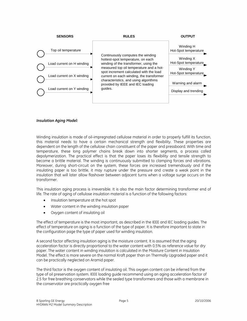
SENSORS RULES OUTPUT
Top oil temperature
Load current in winding H
Winding HHot-Spot temperature
Continuously computes the windinghottest-spot temperature, on eachwinding of the transformer, using themeasured top oil temperature and a hot-spot increment calculated with the loadcurrent on each winding, the transformercharacteristics, and using algorithmsprovided by IEEE and IEC loadingguides.
Load current on H winding
Load current on X winding
Load current on Y winding
Winding XHot-Spot temperature
Winding YHot-Spot temperature
Warning and alarm
Display and trending
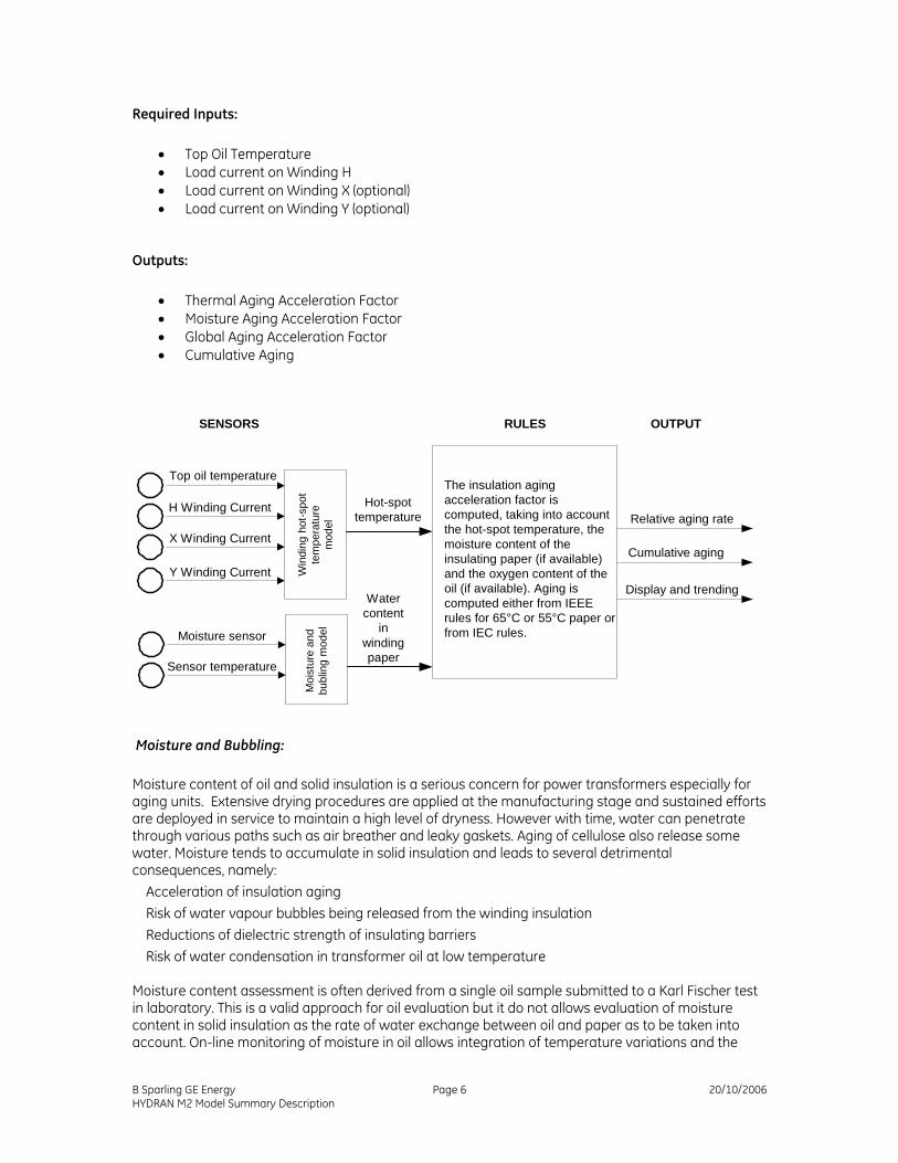
Insulation Aging Model:
Winding insulation is made of oil-impregnated cellulose material in order to properly fulfill its function, this material needs to have a certain mechanical strength and flexibility. These properties are dependent on the length of the cellulose chain constituent of the paper and pressboard. With time and temperature, these long polymer chains break down into shorter segments, a process called depolymerization. The practical effect is that the paper loses its flexibility and tensile strength to become a brittle material. The winding is continuously submitted to clamping forces and vibrations. Moreover, during short-circuit on the system, these forces are increased tremendously and if the insulating paper is too brittle, it may rupture under the pressure and create a weak point in the insulation that will later allow flashover between adjacent turns when a voltage surge occurs on the transformer. This insulation aging process is irreversible. It is also the main factor determining transformer end of life. The rate of aging of cellulose insulation material is a function of the following factors:
• Insulation temperature at the hot spot • Water content in the winding insulation paper • Oxygen content of insulating oil
The effect of temperature is the most important, as described in the IEEE and IEC loading guides. The effect of temperature on aging is a function of the type of paper. It is therefore important to state in the configuration page the type of paper used for winding insulation. A second factor affecting insulation aging is the moisture content. It is assumed that the aging acceleration factor is directly proportional to the water content with 0.5% as reference value for dry paper. The water content in winding insulation is calculated in the Moisture Content in Insulation Model. The effect is more severe on the normal Kraft paper than on Thermally Upgraded paper and it can be practically neglected on Aramid paper. The third factor is the oxygen content of insulating oil. This oxygen content can be inferred from the type of oil preservation system. IEEE loading guide recommend using an aging acceleration factor of 2.5 for free breathing conservators while the sealed type transformers and those with a membrane in the conservator are practically oxygen free
B Sparling GE Energy Page 5 20/10/2006 HYDRAN M2 Model Summary Description
Required Inputs:
• Top Oil Temperature • Load current on Winding H • Load current on Winding X (optional) • Load current on Winding Y (optional)
The insulation agingacceleration factor iscomputed, taking into accountthe hot-spot temperature, themoisture content of theinsulating paper (if available)and the oxygen content of theoil (if available). Aging iscomputed either from IEEErules for 65°C or 55°C paper orfrom IEC rules.
Cumulative aging
Display and trending
Top oil temperature
H Winding Current
X Winding Current
Y Winding Current Win
ding
hot
-spo
tte
mpe
ratu
rem
odel
Moisture sensor
Sensor temperature
Moi
stur
e an
dbu
blin
g m
odel
Hot-spottemperature
Watercontent
inwindingpaper
Moisture and Bubbling: Moisture content of oil and solid insulation is a serious concern for power transformers especially for aging units. Extensive drying procedures are applied at the manufacturing stage and sustained efforts are deployed in service to maintain a high level of dryness. However with time, water can penetrate through various paths such as air breather and leaky gaskets. Aging of cellulose also release some water. Moisture tends to accumulate in solid insulation and leads to several detrimental consequences, namely:
Acceleration of insulation aging Risk of water vapour bubbles being released from the winding insulation Reductions of dielectric strength of insulating barriers Risk of water condensation in transformer oil at low temperature
Moisture content assessment is often derived from a single oil sample submitted to a Karl Fischer test in laboratory. This is a valid approach for oil evaluation but it do not allows evaluation of moisture content in solid insulation as the rate of water exchange between oil and paper as to be taken into account. On-line monitoring of moisture in oil allows integration of temperature variations and the
B Sparling GE Energy Page 6 20/10/2006 HYDRAN M2 Model Summary Description
computation of a dependable value for moisture content in the various components of the solid insulation system even if they are at different temperatures and characterized by different diffusion rates. The most critical part of the winding insulation is the top of the winding that operate at the hot-spot temperature. This is the area where the aging is most severe and the effect of water content can be computed. The determination of critical temperature for bubble evolution takes into account atmospheric pressure, oil pressure above hot-spot area and the amount of gas dissolved in oil. The moisture sensor continuously monitors the relative moisture saturation in the oil and the temperature of oil at the sensor location. A filtering is applied to remove effect of cyclic heating created by the sensor to ensure oil circulation. This filtered value is used to calculate the absolute value of water content in oil, the temperature of water condensation and the relative saturation at the reference temperature. Since oil and winding temperature varies continuously, this moving target is used with an integrating algorithm taking into account diffusion time constant and temperature. The calculated value of water content in winding insulation allows prediction of bubbling temperature. It is also used in the insulation-aging model.
Required Inputs:
• Top Oil Temperature • Load current on Winding
Outputs:
• Water-Oil Condensation Temperature This is the critical temperature (°C )for the formation of free water in insulating oil when a wet transformer is allowed to cool down rapidly. If the water dissolved in the oil does not have sufficient time to migrate back to the cellulose insulation, droplets of free water may precipitate in the oil. This create a hazard for dielectric failure should the transformer be reenergized in this condition.
• Moisture Content in Winding Paper This value is expressed in percentage weigh by weight.
• Moisture Content in Winding Paper Valid Delay Migration of moisture between oil and paper is a slow process governed by moisture content, and diffusion time constant. At system commissioning it is not possible to provide immediately a value of moisture content in paper. Data may need to be integrated over several days or week before a reliable value can be displayed. This delay is calculated considering current temperature conditions and time elapsed since the system was commissioned.
• Winding Bubbling Temperature Residual moisture in the winding insulation can release free gas bubbles if the hot-spot temperature is too high or increasing rapidly. The bubble inception temperature is function of moisture content in paper and also oil pressure and partial vapour pressure in the area of the winding hot spot.
• Winding Bubbling Temperature Margin This is the difference between the bubbling inception temperature and the actual winding hot spot temperature.
B Sparling GE Energy Page 7 20/10/2006 HYDRAN M2 Model Summary Description
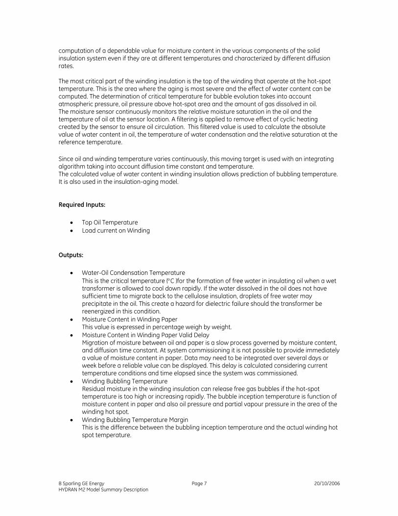
Alarms:
• Water-Oil Condensation Temperature Alarm This alarm is normally set to alert the operator when the condensation temperature is above the minimum temperature that can be observed on the transformer, should it be suddenly remove from service. This value can be configured from -40°C to +20°C with a default value of -20°C.
• Bubbling Temperature Margin Alarm A significant margin should be maintained at all time to avoid occurrence of free bubbles circulation in the cooling oil. This margin can be configured from 0 to 50°C with a default value of 20°C
SENSORS RULES OUTPUT
Bubbling temperature
From the relative saturation of theinsulating oil and temperature ofthe moisture sensor, the relative oilsaturation in the hot-spot area andthe bottom part of pressboardbarriers is calculated.Moisture content in paper isderived from moisture in oil,considering diffusion time constantand insulation thickness.The bubbling temperature isevaluated from the moisturecontent of the winding insulation.The absolute water content of oil(ppm) is determined along with oiltemperature leading to watercondensation.
Bubblingsafety marginTop oil temp.
H winding current
X winding current
Y winding current Win
ding
hot
-spo
tte
mpe
ratu
rem
odel
Moisture sensor
Sensor temperature
Hot-spottemp.
Water content ofwinding paper
Absolute watercontent in oil (ppm)
Water-in-oilcondensationtemperature
Moisture Content in Insulating Barrier:
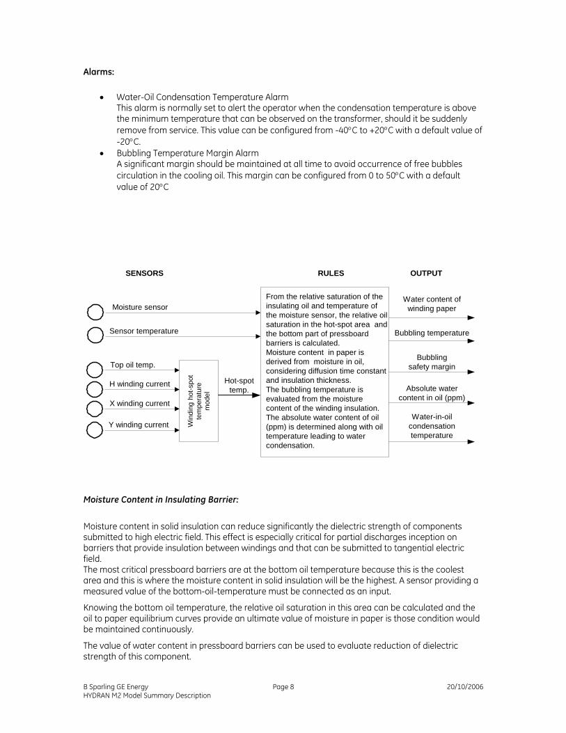
Moisture content in solid insulation can reduce significantly the dielectric strength of components submitted to high electric field. This effect is especially critical for partial discharges inception on barriers that provide insulation between windings and that can be submitted to tangential electric field. The most critical pressboard barriers are at the bottom oil temperature because this is the coolest area and this is where the moisture content in solid insulation will be the highest. A sensor providing a measured value of the bottom-oil-temperature must be connected as an input.
Knowing the bottom oil temperature, the relative oil saturation in this area can be calculated and the oil to paper equilibrium curves provide an ultimate value of moisture in paper is those condition would be maintained continuously.
The value of water content in pressboard barriers can be used to evaluate reduction of dielectric strength of this component.
B Sparling GE Energy Page 8 20/10/2006 HYDRAN M2 Model Summary Description
Required Inputs: • Bottom Oil Temperature
Outputs: • Moisture Content in Insulating Barrier • Moisture Content in Insulating Barrier Valid Delay
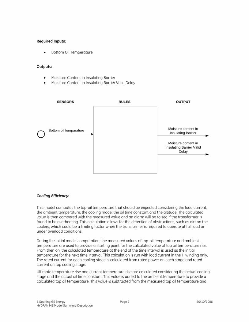
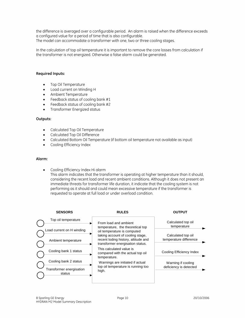
This model computes the top-oil temperature that should be expected considering the load current, the ambient temperature, the cooling mode, the oil time constant and the altitude. The calculated value is then compared with the measured value and an alarm will be raised if the transformer is found to be overheating. This calculation allows for the detection of obstructions, such as dirt on the coolers, which could be a limiting factor when the transformer is required to operate at full load or under overload conditions. During the initial model computation, the measured values of top-oil temperature and ambient temperature are used to provide a starting point for the calculated value of top oil temperature rise. From then on, the calculated temperature at the end of the time interval is used as the initial temperature for the next time interval. This calculation is run with load current in the H winding only. The rated current for each cooling stage is calculated from rated power on each stage and rated current on top cooling stage.
Ultimate temperature rise and current temperature rise are calculated considering the actual cooling stage and the actual oil time constant. This value is added to the ambient temperature to provide a calculated top oil temperature. This value is subtracted from the measured top oil temperature and
B Sparling GE Energy Page 9 20/10/2006 HYDRAN M2 Model Summary Description
the difference is averaged over a configurable period. An alarm is raised when the difference exceeds a configured value for a period of time that is also configurable. The model can accommodate a transformer with one, two or three cooling stages. In the calculation of top oil temperature it is important to remove the core losses from calculation if the transformer is not energized. Otherwise a false alarm could be generated.
Required Inputs:
• Top Oil Temperature • Load current on Winding H • Ambient Temperature • Feedback status of cooling bank #1 • Feedback status of cooling bank #2 • Transformer Energized status
Outputs:
• Calculated Top Oil Temperature • Calculated Top Oil Difference • Calculated Bottom Oil Temperature (if bottom oil temperature not available as input) • Cooling Efficiency Index
Alarm:
• Cooling Efficiency Index Hi alarm This alarm indicates that the transformer is operating at higher temperature than it should, considering the recent load and recent ambient conditions. Although it does not present an immediate threats for transformer life duration, it indicate that the cooling system is not performing as it should and could mean excessive temperature if the transformer is requested to operate at full load or under overload condition.
SENSORS RULES OUTPUT
Top oil temperature
Load current in winding H
Calculated top oiltemperature
From load and ambienttemperature, the theoretical topoil temperature is computedtaking account of cooling stage,recent loding history, altitude andtransformer energisation status.This calculated value iscompared with the actual top oiltemperature. Warnings are initiated if actualtop oil temperature is running toohigh.
Load current on H winding
Ambient temperatureCalculated top oil
temperature difference
Cooling Efficiency Index
Warning if coolingdeficiency is detected
Cooling bank 1 status
Cooling bank 2 status
Transformer energisationstatus
B Sparling GE Energy Page 10 20/10/2006 HYDRAN M2 Model Summary Description
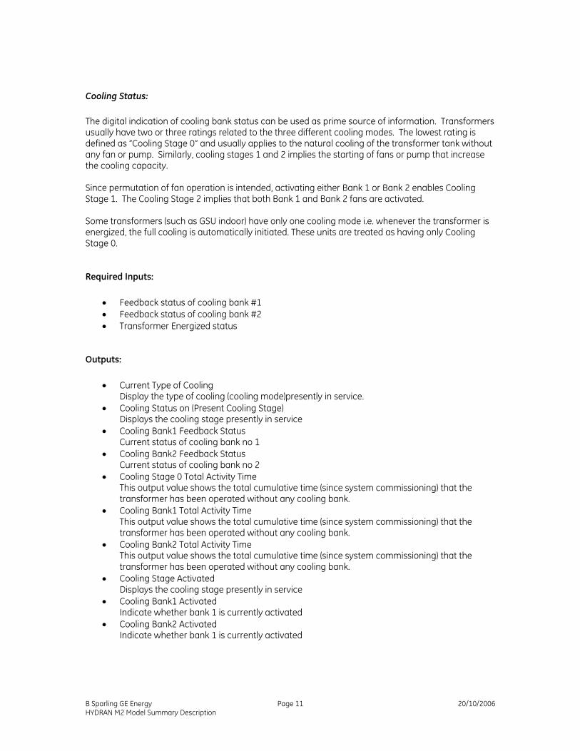
Cooling Status: The digital indication of cooling bank status can be used as prime source of information. Transformers usually have two or three ratings related to the three different cooling modes. The lowest rating is defined as “Cooling Stage 0” and usually applies to the natural cooling of the transformer tank without any fan or pump. Similarly, cooling stages 1 and 2 implies the starting of fans or pump that increase the cooling capacity. Since permutation of fan operation is intended, activating either Bank 1 or Bank 2 enables Cooling Stage 1. The Cooling Stage 2 implies that both Bank 1 and Bank 2 fans are activated. Some transformers (such as GSU indoor) have only one cooling mode i.e. whenever the transformer is energized, the full cooling is automatically initiated. These units are treated as having only Cooling Stage 0.
Required Inputs: • Feedback status of cooling bank #1 • Feedback status of cooling bank #2 • Transformer Energized status
Outputs:
• Current Type of Cooling Display the type of cooling (cooling mode)presently in service.
• Cooling Status on (Present Cooling Stage) Displays the cooling stage presently in service
• Cooling Bank1 Feedback Status Current status of cooling bank no 1
• Cooling Bank2 Feedback Status Current status of cooling bank no 2
• Cooling Stage 0 Total Activity Time This output value shows the total cumulative time (since system commissioning) that the transformer has been operated without any cooling bank.
• Cooling Bank1 Total Activity Time This output value shows the total cumulative time (since system commissioning) that the transformer has been operated without any cooling bank.
• Cooling Bank2 Total Activity Time This output value shows the total cumulative time (since system commissioning) that the transformer has been operated without any cooling bank.
• Cooling Stage Activated Displays the cooling stage presently in service
• Cooling Bank1 Activated Indicate whether bank 1 is currently activated
• Cooling Bank2 Activated Indicate whether bank 1 is currently activated
B Sparling GE Energy Page 11 20/10/2006 HYDRAN M2 Model Summary Description
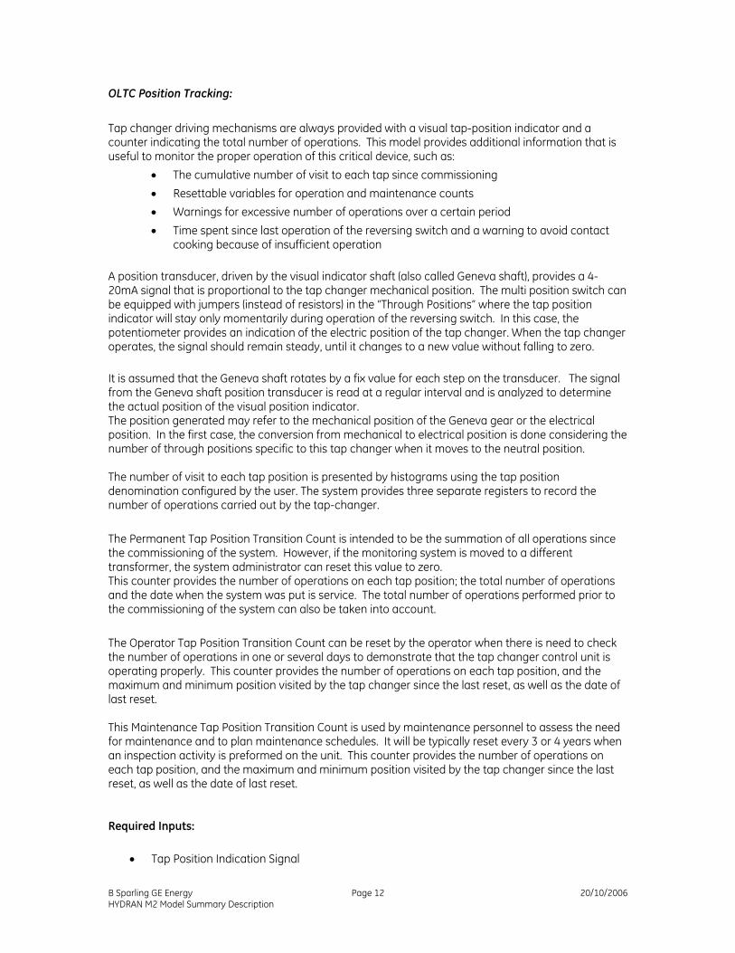
OLTC Position Tracking:
Tap changer driving mechanisms are always provided with a visual tap-position indicator and a counter indicating the total number of operations. This model provides additional information that is useful to monitor the proper operation of this critical device, such as:
• The cumulative number of visit to each tap since commissioning • Resettable variables for operation and maintenance counts • Warnings for excessive number of operations over a certain period • Time spent since last operation of the reversing switch and a warning to avoid contact
cooking because of insufficient operation A position transducer, driven by the visual indicator shaft (also called Geneva shaft), provides a 4-20mA signal that is proportional to the tap changer mechanical position. The multi position switch can be equipped with jumpers (instead of resistors) in the “Through Positions” where the tap position indicator will stay only momentarily during operation of the reversing switch. In this case, the potentiometer provides an indication of the electric position of the tap changer. When the tap changer operates, the signal should remain steady, until it changes to a new value without falling to zero. It is assumed that the Geneva shaft rotates by a fix value for each step on the transducer. The signal from the Geneva shaft position transducer is read at a regular interval and is analyzed to determine the actual position of the visual position indicator. The position generated may refer to the mechanical position of the Geneva gear or the electrical position. In the first case, the conversion from mechanical to electrical position is done considering the number of through positions specific to this tap changer when it moves to the neutral position. The number of visit to each tap position is presented by histograms using the tap position denomination configured by the user. The system provides three separate registers to record the number of operations carried out by the tap-changer. The Permanent Tap Position Transition Count is intended to be the summation of all operations since the commissioning of the system. However, if the monitoring system is moved to a different transformer, the system administrator can reset this value to zero. This counter provides the number of operations on each tap position; the total number of operations and the date when the system was put is service. The total number of operations performed prior to the commissioning of the system can also be taken into account. The Operator Tap Position Transition Count can be reset by the operator when there is need to check the number of operations in one or several days to demonstrate that the tap changer control unit is operating properly. This counter provides the number of operations on each tap position, and the maximum and minimum position visited by the tap changer since the last reset, as well as the date of last reset. This Maintenance Tap Position Transition Count is used by maintenance personnel to assess the need for maintenance and to plan maintenance schedules. It will be typically reset every 3 or 4 years when an inspection activity is preformed on the unit. This counter provides the number of operations on each tap position, and the maximum and minimum position visited by the tap changer since the last reset, as well as the date of last reset.
Required Inputs: • Tap Position Indication Signal
B Sparling GE Energy Page 12 20/10/2006 HYDRAN M2 Model Summary Description
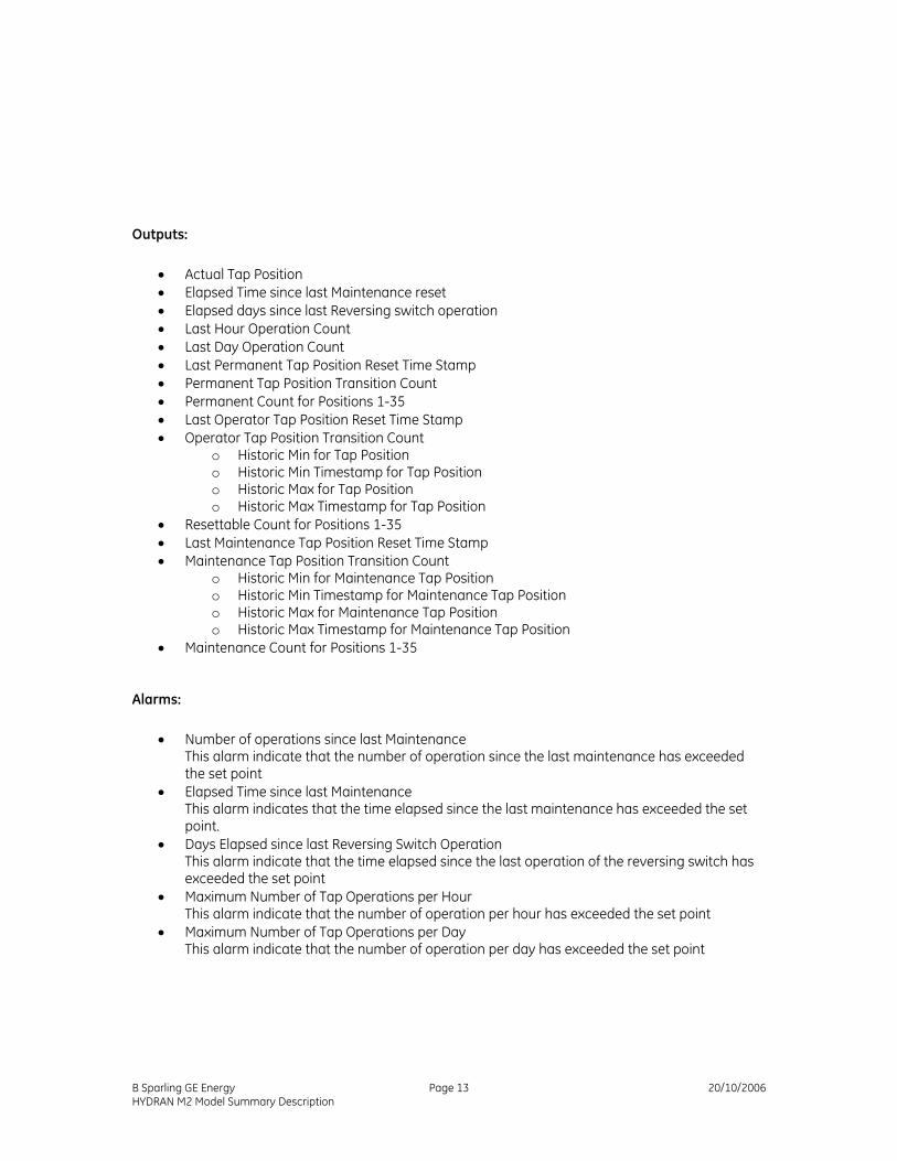
Outputs: • Actual Tap Position • Elapsed Time since last Maintenance reset • Elapsed days since last Reversing switch operation • Last Hour Operation Count • Last Day Operation Count • Last Permanent Tap Position Reset Time Stamp • Permanent Tap Position Transition Count • Permanent Count for Positions 1-35 • Last Operator Tap Position Reset Time Stamp • Operator Tap Position Transition Count
o Historic Min for Tap Position o Historic Min Timestamp for Tap Position o Historic Max for Tap Position o Historic Max Timestamp for Tap Position
• Resettable Count for Positions 1-35 • Last Maintenance Tap Position Reset Time Stamp • Maintenance Tap Position Transition Count
o Historic Min for Maintenance Tap Position o Historic Min Timestamp for Maintenance Tap Position o Historic Max for Maintenance Tap Position o Historic Max Timestamp for Maintenance Tap Position
• Maintenance Count for Positions 1-35
Alarms:
• Number of operations since last Maintenance This alarm indicate that the number of operation since the last maintenance has exceeded the set point
• Elapsed Time since last Maintenance This alarm indicates that the time elapsed since the last maintenance has exceeded the set point.
• Days Elapsed since last Reversing Switch Operation This alarm indicate that the time elapsed since the last operation of the reversing switch has exceeded the set point
• Maximum Number of Tap Operations per Hour This alarm indicate that the number of operation per hour has exceeded the set point
• Maximum Number of Tap Operations per Day This alarm indicate that the number of operation per day has exceeded the set point
B Sparling GE Energy Page 13 20/10/2006 HYDRAN M2 Model Summary Description
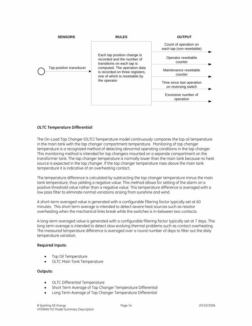
SENSORS RULES OUTPUT
Tap position transducer
Count of operation oneach tap (non resettable)
Each tap position change isrecorded and the number oftransitions on each tap iscomputed. The operation datais recorded on three registers,one of which is resettable bythe operator
Operator resettablecounter
Maintenance resettablecounter
Time since last operationon reversing switch
Excessive number ofoperation
OLTC Temperature Differential:
The On-Load Tap Changer (OLTC) Temperature model continuously compares the top oil temperature in the main tank with the tap changer compartment temperature. Monitoring of tap changer temperature is a recognized method of detecting abnormal operating conditions in the tap changer. This monitoring method is intended for tap changers mounted on a separate compartment on the transformer tank. The tap changer temperature is normally lower than the main tank because no heat source is expected in the tap changer. If the tap changer temperature rises above the main tank temperature it is indicative of an overheating contact. The temperature difference is calculated by subtracting the tap changer temperature minus the main tank temperature, thus yielding a negative value. This method allows for setting of the alarm on a positive threshold value rather than a negative value. This temperature difference is averaged with a low pass filter to eliminate normal variations arising from sunshine and wind. A short-term averaged value is generated with a configurable filtering factor typically set at 60 minutes. This short term average is intended to detect severe heat sources such as resistor overheating when the mechanical links break while the switches is in-between two contacts. A long-term averaged value is generated with a configurable filtering factor typically set at 7 days. This long-term average is intended to detect slow evolving thermal problems such as contact overheating. The measured temperature difference is averaged over a round number of days to filter out the daily temperature variation.
Required Inputs: • Top Oil Temperature • OLTC Main Tank Temperature
Outputs:
• OLTC Differential Temperature • Short Term Average of Tap Changer Temperature Differential • Long Term Average of Tap Changer Temperature Differential
B Sparling GE Energy Page 14 20/10/2006 HYDRAN M2 Model Summary Description
Alarms:
• OLTC Short Term Temperature Differential Hi Alarm
A tap changer running 5°C above the main tank should be closely monitored. This value is configurable from 0°C to 30°C.
• OLTC Short Term Temperature Differential Hi-Hi Alarm A tap changer running 15°C above the main tank is a serious concern. This value is configurable from 0°C to 40°C.
• OLTC Long Term Temperature Differential Hi Alarm A tap changer running continuously 3°C above the main tank should be closely monitored. This value is configurable from 0°C to 20°C.
• OLTC Long Term Temperature Differential Hi-Hi Alarm
A tap changer running continuously at 10°C above the main tank is serious concern. This value is configurable from 0°C to 30°C.
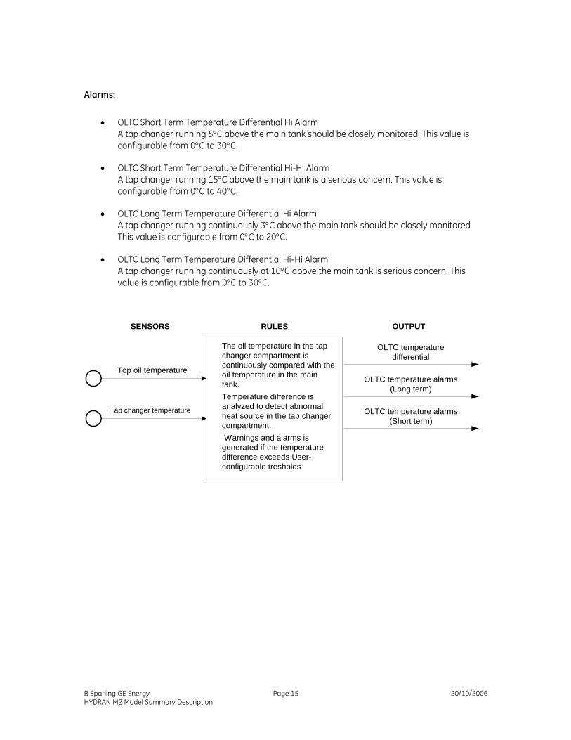
SENSORS RULES OUTPUT
Top oil temperature
OLTC temperaturedifferential
The oil temperature in the tapchanger compartment iscontinuously compared with theoil temperature in the maintank.Temperature difference isanalyzed to detect abnormalheat source in the tap changercompartment. Warnings and alarms isgenerated if the temperaturedifference exceeds User-configurable tresholds
OLTC temperature alarms(Long term)
OLTC temperature alarms(Short term)
Tap changer temperature
B Sparling GE Energy Page 15 20/10/2006 HYDRAN M2 Model Summary Description