SUDAS District Meeting Agenda April 2020 I. Administrative A. Minutes of the previous meeting and schedule of district meetings The minutes of the February webinar will be considered. The schedule of district meetings will be presented. II. Design Manual Items A. General provisions (Chapter 1) Updated the chapter based on current practices. B. Water main LUST interaction (Section 4C-1) Modified to match Iowa DNR permit requirements for interaction of water mains and LUST sites. C. Minimum street width alternative (Sections 5C-1 and 5C-2) Updated Table 5C-1.01 by adding an additional 27 feet back-to-back street width and a 48 foot cul-de-sac radius alternative when agencies have larger fire apparatus. D. Lane width and capacity (Section 5C-2, A) Updated to reflect new lane width and capacity relationships. E. Driveway design for low volume residential streets (Sections 5L-3 and 5L-4) Updated point of width measurement, established width based on number of garage stalls, clarified joint driveway width, and updated distance from intersections. F. Utility locating site restoration (Design Section 5I-3; Spec Sections 3020 and 7040) Added information to address re-establishment of the pavement following cutting of core holes in pavements for utility location. III. Specifications Manual Items A. Abbreviations and definitions (Section 1010) Added abbreviations and definitions for commonly used terms. B. Deleted bid items (Section 1040, 1.06, C) Added information on paying for delivered materials if the bid item is deleted. C. Project area maintenance (Section 1070, 2.08, C) Added clarification concerning maintenance of the work area during the project. D. Visual inspection of sewers (Section 4060, 3.02) Deleted requirement for lamping sewers and culverts. E. Water main pipe options (Section 5010, 2.01, 2.03, and 3.04) Deleted prestressed concrete cylinder pipe as a standard water main pipe since it has limited use and application. F. Fire hydrants (Spec Section 5020, 3.03, F and Design Section 4C-1, E) Clarified fire hydrant placement and orientation to meet 2018 International Fire code. G. Steps in deep structures (Section 6010, 2.13; Figures SW-301, SW-303, SW-304, SW-305, SW-401, SW-404, SW-405) Added steps for structures deeper than 20 feet. H. Cross slope for sidewalks, driveways, and shared use paths (Section 7030, 3.04) Clarified maximum, target, and minimum cross slope requirements. I. Water for seeding (Section 9010, 1.08, D) Modified the measurement and payment for watering to eliminate confusion of MGAL, which has been misinterpreted as a million gallons rather than 1,000 gallons.
Transcript
SUDAS District Meeting Agenda
April 2020
I. Administrative
A. Minutes of the previous meeting and schedule of district meetings
The minutes of the February webinar will be considered. The schedule of district meetings
will be presented.
II. Design Manual Items
A. General provisions (Chapter 1)
Updated the chapter based on current practices.
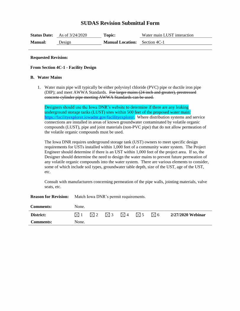
B. Water main LUST interaction (Section 4C-1)
Modified to match Iowa DNR permit requirements for interaction of water mains and
LUST sites.
C. Minimum street width alternative (Sections 5C-1 and 5C-2)
Updated Table 5C-1.01 by adding an additional 27 feet back-to-back street width and a 48
foot cul-de-sac radius alternative when agencies have larger fire apparatus.
D. Lane width and capacity (Section 5C-2, A)
Updated to reflect new lane width and capacity relationships.
E. Driveway design for low volume residential streets (Sections 5L-3 and 5L-4)
Updated point of width measurement, established width based on number of garage stalls,
clarified joint driveway width, and updated distance from intersections.
F. Utility locating site restoration (Design Section 5I-3; Spec Sections 3020 and 7040)
Added information to address re-establishment of the pavement following cutting of core
holes in pavements for utility location.
III. Specifications Manual Items
A. Abbreviations and definitions (Section 1010)
Added abbreviations and definitions for commonly used terms.
B. Deleted bid items (Section 1040, 1.06, C)
Added information on paying for delivered materials if the bid item is deleted.
C. Project area maintenance (Section 1070, 2.08, C)
Added clarification concerning maintenance of the work area during the project.
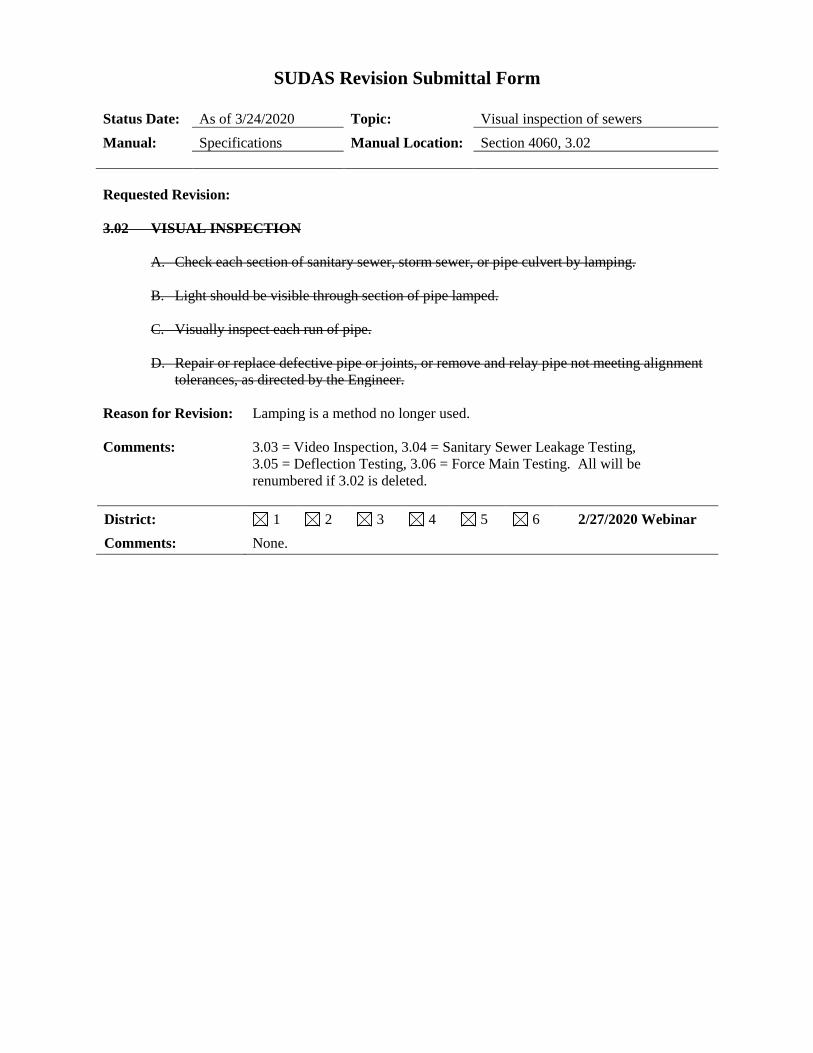
D. Visual inspection of sewers (Section 4060, 3.02)
Deleted requirement for lamping sewers and culverts.
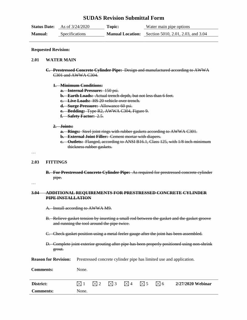
E. Water main pipe options (Section 5010, 2.01, 2.03, and 3.04)
Deleted prestressed concrete cylinder pipe as a standard water main pipe since it has limited
use and application.
F. Fire hydrants (Spec Section 5020, 3.03, F and Design Section 4C-1, E)
Clarified fire hydrant placement and orientation to meet 2018 International Fire code.
G. Steps in deep structures (Section 6010, 2.13; Figures SW-301, SW-303, SW-304, SW-305,
SW-401, SW-404, SW-405)
Added steps for structures deeper than 20 feet.
H. Cross slope for sidewalks, driveways, and shared use paths (Section 7030, 3.04)
Clarified maximum, target, and minimum cross slope requirements.
I. Water for seeding (Section 9010, 1.08, D)
Modified the measurement and payment for watering to eliminate confusion of MGAL,
which has been misinterpreted as a million gallons rather than 1,000 gallons.
IV. Other
A. Discussion items
• Curing of sidewalks, driveways, and shared use paths - change default to cure?
• Any confusion about proof rolling and the loading on the trucks?
• Should we add specifications for PVC/HDPE concrete pipe liner to combat caustic
sewage?
• Should we modify DIP water main specifications to pressure class from thickness class?
• Other?
B. Iowa Public Works Service Bureau update
An update on the project will be given.
C. Products and/or research
District committee members can suggest new products to be proposed for SUDAS manual
inclusion; suggestions for potential research projects can also be made at this time.
V. Next Meeting
District 1 - October 14 District 4 - October 6
District 2 - October 15 District 5 - October 22
District 3 - October 8 District 6 - October 21
I A
SUDAS District Webinar Minutes
February 27, 2020
The meeting was called to order at 9:01 am by Paul Wiegand.
District 1 Members Present:
Ben McAlister, City of West Des Moines
Chadd Kahlsdorf, Bolton & Menk
Daniel Harness, Iowa DOT
Danny Knispel, City of Altoona
Darwin Larson, APAI
David Bovee, HR Green
Eric Johnsen, Iowa DOT
ISG
Jeff May, City of Clive
John Dostart, City of Altoona
John Gade, Fox Engineering
John Larson, City of Urbandale
Larry Workman, City of Pleasant Hill
Nichole Sungren, MSA Professional Services
Sarah Okerlund, Iowa DOT
Steve Klocke, Snyder & Associates
Tara Naber, Iowa DNR
District 2 Members Present:
Jay Waddingham, Franklin County
Mark Durbhan, AECOM
Tim Moreau, Veenstra & Kimm, Inc.
District 3 Members Present:
Brian Catus, Iowa DOT
Bryan Wells, DGR Engineering
Cody Forch, JEO Consulting Group
Dan Eckert, Dickinson County
David Carney, City of Sioux City
Justin Pottorff, City of Sioux City
Mark Nahra, Woodbury County
Randy Krauel, City of Carroll
District 4 Members Present:
Dave Vermillion, City of Council Bluffs
Matt Cox, City of Council Bluffs
Mike Hackett, Madison County
Scott Reelfs, HGM Associates Inc.
District 5 Members Present:
Akhilesh Pal, City of Oskaloosa
Brad Skinner, Appanoose County
Christy VanBuskirk, Iowa DOT
Jesse Howe, City of Burlington
Ryne Thornburg, Van Buren County
Steve Hausner, French-Reneker
District 6 Members Present:
Aaron Granquist, HR Green
Bob Schiesl, City of Dubuque
Brenna Fall, City of Cedar Rapids
Brent Morlok, City of Bettendorf
Brian Schadt, City of Davenport
Darin Andresen, City of Marion
Greg Shuger, Stanley Consultants
Joe Welter, City of Iowa City
Ken DeKeyser, City of Cedar Rapids
Lee Tippe, City of Cedar Rapids
Mark Crawford, Crawford Engineering
Michaela LeClair, HDR, Inc.
Ryan Foley, City of Coralville
Scott Larson, City of Coralville
Taylor Theulen, Stanley Consultants
Staff Present:
Paul Wiegand, SUDAS Beth Richards, SUDAS
I. Administrative
A. Schedule of district meetings
The proposed schedule of district meetings was presented.
B. Board of Directors meeting minutes
A summary of actions taken by the Board during the November 2019 electronic vote was presented.
II. Design Manual Items
A. General provisions (Chapter 1)
Updated the chapter based on current practices. In Section 1E-1, C, add “funding source representative” to
the list of groups invited to the pre-construction meeting. Also add “funding source requirements” and
“review of adjacent property owner needs” to the list of items to be identified and discussed.
B. Water main LUST interaction (Section 4C-1)
Modified to match Iowa DNR permit requirements for interaction of water mains and LUST sites. Iowa
DNR was in contact with staff and agreed with the proposed language. No comments.
C. Minimum street width alternative (Sections 5C-1 and 5C-2)
Updated Table 5C-1.01 by adding an additional 27 feet back-to-back street width and a 48 foot cul-de-sac
radius alternative when agencies have larger fire apparatus. No comments.
D. Lane width and capacity (Section 5C-2, A)
Updated to reflect new lane width and capacity relationships. No comments.
E. Driveway design for low volume residential streets (Sections 5L-3 and 5L-4)
Updated point of width measurement, established width based on number of garage stalls, clarified joint
driveway width, and updated distance from intersections. One person questioned if you could measure
from the front of the sidewalk. Another person suggested measuring widths at the end of the driveway curb
radius when adjacent to a commercial area.
F. Utility locating site restoration (Design Section 5I-3; Spec Sections 3020 and 7040)
Added information to address re-establishment of the pavement following cutting of core holes in
pavements for utility location. Cedar Rapids has a figure and will share it with SUDAS staff.
III. Specifications Manual Items
A. Abbreviations and definitions (Section 1010)
Adding abbreviations and definitions for commonly used terms. No comments.
B. Project area maintenance (Section 1070, 2.08, C)
Added clarification concerning maintenance of the work area during the project. No comments.
C. Visual inspection of sewers (Section 4060, 3.02)
Deleted requirement for lamping sewers and culverts. No comments. Paul recently learned of a new process
involving laser profiling and will explore this as another potential alternative.
D. Water main pipe options (Section 5010, 2.01, 2.03, and 3.04)
Deleted prestressed concrete cylinder pipe as a standard water main pipe since it has limited use and
application. No comments.
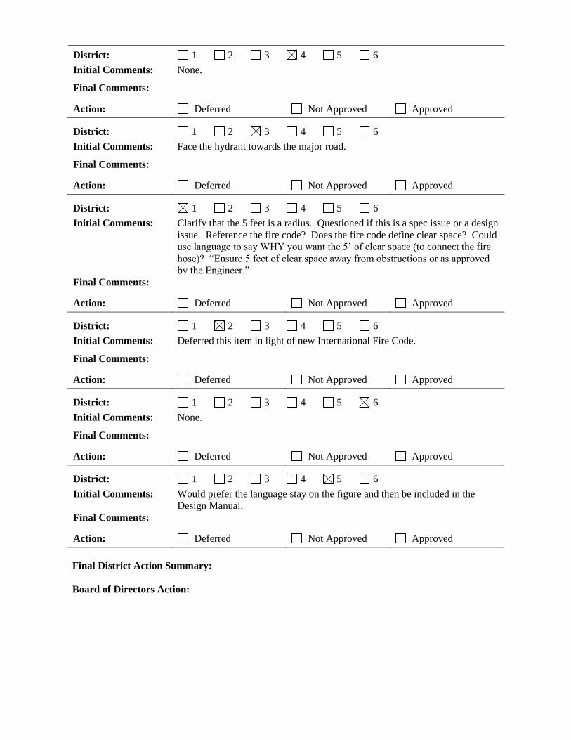
E. Fire hydrants (Spec Section 5020, 3.03, F and Design Section 4C-1, E)
Clarified fire hydrant placement and orientation to meet 2018 International Fire code. No comments.
F. Steps in deep structures (Section 6010, 2.13)
Added steps for structures deeper than 20 feet. No comments.
G. Cross slope for sidewalks, driveways, and shared use paths (Section 7030, 3.04)
Clarified maximum, target, and minimum cross slope requirements. No comments.
H. Water for seeding (Section 9010, 1.08, D)
Modified the measurement and payment for watering to eliminate confusion of MGAL, which has been
misinterpreted as a million gallons rather than 1,000 gallons. No comments.
IV. Other
A. Discussion items
• Curing of sidewalks, driveways, and shared use paths - change default to cure? One person said yes.
• Any confusion about proof rolling and the loading on the trucks? Based on input, more discussion is
necessary.
• Should we add specifications for PVC/HDPE concrete pipe liner to combat caustic sewage? Several
participants commented that they would like to see this added.
• Should we expand information or establish criteria when bid items are deleted? Based on input,
modifications to the language will be proposed.
• Bedding/joint/void filler aggregate discrepancy - ASTM versus DOT? No comments.
• Other? None.
B. Iowa Public Works Service Bureau update
An update on the project was presented.
C. Products and/or research
Paul mentioned the research focus group meeting prior to APWA Iowa Chapter Spring Conference. One
made a new product suggestion - pressure class ductile iron rather than Class 52.
The meeting was adjourned at 10:28 am. Minutes were recorded by Beth Richards, SUDAS Program Coordinator.
District Meeting Dates for 2020
District: District 1 District 2 District 3 District 4 District 5 District 6
Times: 10 am - 1 pm 10 am - 1 pm 10 am - 1 pm 10 am - 1 pm 10 am - 1 pm 10 am - 1 pm
Location: Snyder & Assoc.
Ankeny
City Hall
Charles City
ISG
Storm Lake
Snyder & Assoc.
Atlantic
Jefferson County
Extension Office
Fairfield
Iowa DOT
District 6 Office
Cedar Rapids
Dates:
All district webinar - February 27, 2020 at 9:00 am
April 15 *April 14 April 9 April 7 *April 21 April 22
October 14 October 15 October 8 October 6 October 22 October 21
* Meetings do not follow normal schedule
The next SUDAS Board of Directors meeting will be _____________ at 10:00 am at the ISU Alumni Center in Ames.
II A
SUDAS Revision Submittal Form
Status Date: As of 3/24/2020 Topic: General provisions
Manual: Design Manual Location: Chapter 1
Requested Revision: See attached.
Reason for Revision: Updated based on current practices.
Comments: None.
District: 1 2 3 4 5 6 2/27/2020 Webinar
Comments:
In Section 1E-1, C, add “funding source representative” to the list of groups
invited to the pre-construction meeting. Also add “funding source
requirements” and “review of adjacent property owner needs” to the list of
items to be identified and discussed. Note - done.
District: 1 2 3 4 5 6
Initial Comments: None.
Final Comments:
Action: Deferred Not Approved Approved
District: 1 2 3 4 5 6
Initial Comments: • 1B-1, B - reference to figure that is being deleted.
• 1B-1, K and L - make sure to strike “ditch” and insert “open channel”.
• Suggest deleting the submittal checklist because you can’t possibly cover
everything that each agency would want.
• 1F-1, 3, a (sewer plans) - remove “if different from the design elevation”
• Suggest moving the proprietary products list to the archived list or just
state that it’s no longer being maintained
Final Comments:
Action: Deferred Not Approved Approved
District: 1 2 3 4 5 6
Initial Comments: • 1D-4 - include additional numbers to help relate to the type and/or size for
the item?
• Federal government is now leaving it up to the states to decide if products
are appropriate to use (rather than having to get FHWA approval). PIF
process. Final Comments:
Action: Deferred Not Approved Approved
District: 1 2 3 4 5 6
Initial Comments: • 1B-1 - rearrange groupings to have everything under main heading - i.e. -
sanitary sewer is A and then everything sanitary sewer related would be
listed as 1, 2, 3, etc.
• 1E-1, C - add change orders. Timing for contractor payments. Final Comments:
Action: Deferred Not Approved Approved
District: 1 2 3 4 5 6
Initial Comments: • Figure 1B-1.05 - Coralville concern about public vs. private
• How common is it to run 2 lines (1B-1.06)? Public footing drain - how
often are those put in? Change description to footing drain collector or
longitudinal subdrain
• Might be worthwhile to include subdrains in the sheet designation list??
• Sample legend - scalable size for certain items? Add a sentence (to lead in
paragraph m) to make sure the legend matches the symbols they actually
use (and make sure it’s complete). Sentence here also about scalable line
weights/sizes, etc. Level of accuracy labels (SUE standard)?
• Font size being at least legible when printed to 11x17 (or whatever the
jurisdiction requires)? (What does Iowa DOT says). (New section has
some language that could be expanded to include this)
• Process in place for what utilities should be submitting to municipalities?
Design plan? As-builts? Part of a permit process? Concern that it might
be creating a headache for cities who have their own utilities. Final Comments:
Action: Deferred Not Approved Approved
District: 1 2 3 4 5 6
Initial Comments: • 1C-1 - submittal checklist - gas, electric, utility, etc? Expand letter o to
cover ADA/PROWAG.
• Bullet for suppliers within the pre-construction meeting?
• Move proprietary products list to archived page. Final Comments:
Action: Deferred Not Approved Approved
Final District Action Summary:
Board of Directors Action:
1A-1
Design Manual
Chapter 1 - General Provisions
1A - General Information
1 Revised: DRAFT
General Information
A. Purpose
The SUDAS Design Manual has been prepared as a mechanism to implement uniform design
standards, procedures, and regulations for the preparation of urban improvement construction plans.
These improvements are those that meet any of the following:
1. Are initiated, designed, and constructed by or under the supervision of the jurisdiction as a public
improvement and maintained by the jurisdiction.
2. Are initiated, designed, and constructed by the private owner/developer's private engineer and
contractor. Upon acceptance of the improvements by the jurisdiction, the improvements are
operated and maintained by the jurisdiction.
Those improvements that require review and approval by the jurisdiction, but will remain under
private ownership, may be required to follow the SUDAS Design Manual. Each jurisdiction will
decide if these types of improvements are to follow the SUDAS Design Manual.
B. Definitions
See the SUDAS Standard Specifications (referred to as SUDAS Specifications) Section 1010 for
definitions and a list of abbreviations.
Construction Inspector or Observer: The person or persons appointed by either the project
engineer or the jurisdictional engineer to inspect all materials used and all work done. Such
inspection may extend to any or all parts of the work and to the preparation or manufacture of the
materials to be used. The inspector is not authorized to revoke, alter, enlarge, or relax the provisions
of the specifications. The inspector will keep the project engineer and the jurisdictional engineer
informed as to the quality and progress of the work and the manner in which it is being done.
Jurisdictional Engineer: The licensed professional engineer designated by the jurisdiction to carry
out the provisions of the SUDAS Design Manual and the jurisdiction’s design supplement, if
applicable.
Project Engineer: The licensed professional engineer who is legally responsible for the design
and/or administration of the project.
C. Intent of the SUDAS Design Manual
The values contained herein are considered fundamental concepts of basic design criteria that will
serve as a framework for satisfactory design on new improvements. The project engineer is
encouraged to develop the design based on this framework and tailored to particular situations that are
consistent with the general purpose and intent of the design criteria through the exercise of sound
engineering judgment. Situations may arise that require special considerations. Therefore, to
eliminate hardships or problems, the jurisdiction may choose to vary the design criteria, procedures,
and regulations. Jurisdictions may have a written design supplement that identifies specific
Chapter 1 - General Provisions Section 1B-2 - Preliminary Plan/Information Development
2 Revised: DRAFT
specific dates must be met. Formal procedures for opening bids should be established in consultation
with the city attorney.
In general, the plans and specifications will be developed for a project identifying specific materials
and processes to accomplish the work. The SUDAS Specifications allow the contractor to choose
some materials unless the jurisdiction has limited that ability. Other contracts include bidding
specific alternates. This allows the jurisdiction to select a particular material or process based on a
predetermined method of analysis. The elements to be used in the analysis should be identified
within the special provisions of the contract as a means of minimizing controversy.
Some contracts may be set up to have a base bid with a series of bid alternates. This is handled in the
project by listing the alternates as separate work items. If this process is used, the project special
provisions should identify how the bid alternates will be considered for contract award.
C. Specific Jurisdictional Requirements
As a part of initiating a project that will be submitted to a jurisdiction for review/approval, it is
important to ascertain if the jurisdiction has special requirements, such as:
• Supplemental information/requirements for the SUDAS Design and Specifications Manuals?
• Any local jurisdiction master plan?
• Who is the jurisdiction’s contact for this project?
• Specific design software or a specific version of the software?
• Specific layer designations for the electronic plans?
• Are 3-D plans required and what should the submittals include?
• Specific legend requirements to be used on the construction plans?
• Specific requirements for survey data collection?
• Specific plan sheet designations and plan organization requirements (i.e. colored plans, sheet size,
etc.)?
• Specific requirements for vertical and horizontal scale on the construction plans?
• Specific construction plan submittal requirements, such as number of printed sets and media
type?
• Submittal and review process?
• Specific products to be used or prohibited?
• Specific review/approval process if a new technology is proposed?
• If not stipulated in the supplemental information, how far should utility services extend beyond
the right-of-way line?
• Are manholes required where private storm sewers are connected to the public storm sewer
system?
• Minimum width requirements for permanent utility easements or a specific form for the
easement?
• Requirements for a permanent easement for access to and maintenance of fire hydrants on a
private fire line?
• Permitting authority from the Iowa DNR for sanitary sewer and water main construction projects?
If so, do you have special permit forms?
• Specific information/criteria needed on the as-built plan?
• Criteria for changes to plans and submittal of variances to design elements?
Other elements that are specific to the type of project may need to be determined. One method to get
the needed information is to schedule a pre-project planning meeting with the jurisdiction staff.
1C-1
Design Manual
Chapter 1 - General Provisions
1C - Submittal Procedures
1 Revised: DRAFT
Submittal Procedures
A. Construction Plans and Specifications Submittal Procedure
1. General: Project engineers and developers seeking approval and acceptance of civil engineering
reports, construction plans, and site plans are required to follow the procedures as established by
each jurisdiction. These procedures are generally outlined in this section. The adherence to these
procedures will assist in an efficient review of engineering plans and reports. Each jurisdiction
reserves the right to modify certain procedures to fit their unique situation.
2. Pre-submittal Meetings: Each jurisdiction may conduct pre-submittal meetings at which
developers may ask questions and obtain direction and/or information from the jurisdiction’s
staff. These meetings may be used by the developer to obtain very basic information about
procedures, practices, or standards as a basis on which to begin development planning.
Alternatively, the applicant may use the meeting as a final check by staff to verify a specific type
of application is complete.
3. Submittal of Public Improvement and Development Plan Application: The development
plan application, site plans, revised site plans, and other public improvements submitted to the
jurisdiction for any project, subdivision, or planned unit development, whether residential, retail,
commercial, or industrial, should include drawings for public improvements including any impact
reports. Initial plan submittals must be marked as “Draft” or “Not for Construction.”
4. Engineering Review Objective: The primary objective of the jurisdictional engineer is to ensure
conformance with the adopted codes, standards, and master plans, as well as to ensure
coordination with adjacent projects, developments, and landowners. The jurisdictional engineer
also completes the initial review and issues comments according to the schedule prescribed by the
jurisdiction to prevent delaying further review by other agencies or impact any other scheduling,
such as subdivision platting.
5. Results of Engineering Review: After the review is completed, the check prints and comments
report will be returned to the project engineer.
6. Revision of Engineering Plans and Reports: The project engineer will make all the revisions
requested on the original plans/report and re-submit until all comments are sufficiently addressed.
Seriously deficient plans may require several reviews prior to approval.
7. Revision of Plans and Reports: When submitting revised plans, drawings, or reports to the
jurisdictional engineer, the re-submittal must contain the following.
a. The revised plans for review.
b. All check prints from previous reviews with copies of the previous plans. Notations should
be made after each comment if the correction was made or justification why a comment is not
valid.
c. If fees are applicable, they must accompany the application.
Chapter 1 - General Provisions Section 1C-1 - Submittal Procedures
2 Revised: DRAFT
If all of the above are not submitted, the re-submittal may be returned without further action until
such time as the submittal is complete.
8. Order of Processing: The following policy regarding order of processing (priority) will be used
for all submittals. Applications are normally processed on a first come basis.
a. Final media for approval.
b. Resubmittal, complete package.
c. Initial submittal, complete package.
When plans are returned to the project engineer for lack of adequate information, or in the event
of re-platting or major site plan revisions after the initial review, the re-submittal will be
considered a new submittal rather than a return. A thorough technical review will be started by
the jurisdiction when adequate information is provided.
9. Approved Plans: When plans or reports have been conditionally approved by the jurisdictional
engineer, the project engineer should submit a minimum of two 11 by 17 inch copies (or as
required by the jurisdiction) of the final plans, certified according to the Iowa Code. Meet the
jurisdictional engineer’s requirements to ensure all lettering and details are legible. Final
construction plans are to be filed as a PDF file on a disk, flash drive, by email, cloud storage, or
other form of media as required by the jurisdiction. If the project relates to a development,
original engineering plans for public improvements may be approved by the jurisdictional
engineer, only after the approval of the preliminary plat, the land dedication, and the subdivision
improvements agreement associated with property.
B. Updates to Previously Approved Plans
1. Construction plans, pavement design reports, drainage reports, site plans, and other documents
are approved initially for 12 months, or as specified by the jurisdiction. If not constructed during
this time period, they automatically become void and must be updated to current criteria before
any further permits can be issued. The jurisdictional engineer may grant an extension to the
construction plans, pavement design reports, and drainage report validity period; provided a) the
development plan, construction plans, or reports have not substantially changed, and b) that other
conditions affecting the development site have not substantially changed or do not require a
modification to approved plans or specifications.
2. Whenever updates or revisions to previously approved construction plans, specifications, or
drainage reports are necessary, the project engineer will submit updates or revisions through the
normal document submittal process. After all jurisdictional engineer comments and revisions
have been incorporated, the construction plans or reports containing revisions may be submitted
for approval.
Chapter 1 - General Provisions Section 1C-1 - Submittal Procedures
3 Revised: DRAFT
C. Submittal Checklist
At a minimum, the following documents should be submitted for review and approval when preparing
final construction plans for public improvements or private improvements subject to approval by the
jurisdiction.
1. Street plan and profile.
2. Storm sewer plan and profile, including details for all structures and material specifications.
3. Culvert plan, profile, and construction detail for structures.
4. Permanent traffic signing and striping plan.
5. Pavement design where required.
6. Grading and erosion control plan.
7. Sanitary sewer plan and profile including details for all structures, material specifications, and
sewer treatment agreement with sewer capacity calculations. Completed permit forms.
8. Water construction plans as approved by the governing jurisdiction or utility with a water supply
agreement and completed permit forms. If these plans represent lines to be installed with the
proposed roadways, the plans must be approved by the jurisdictional engineer.
9. Plan for traffic control during construction.
10. Engineering review and approval fee, if required.
11. All appropriate permits from the jurisdiction and state and federal agencies.
12. Identification of right-of-way and permanent or temporary easements along with any conditions
of use.
13. Stormwater management plan and SWPPP.
14. Geotechnical report.
15. Accessible pedestrian facility plans and documentation.
16. Design variance, if applicable.
1D-1
Design Manual
Chapter 1 - General Provisions
1D - Detailed Plans for Construction of Public
Improvements
1 Revised: DRAFT
Detailed Plans for Construction of Public
Improvements
A. Public Improvement Plan Sheet Requirements
Detailed reproducible plans, certified by a licensed professional engineer in the State of Iowa, should
be filed with the jurisdiction for all work involved in public improvement contracts and/or
agreements.
When providing computer aided design (CAD) files, ensure they contain all break lines used to
develop a 3D file showing coordinates (x,y,z) needed to accurately represent the paper design plans.
Break lines should be shown according to the cross-section below. In addition, break lines within the
3D file should indicate all locations within the project limits where there is a change of slope.
The 3D file should be available to potential bidders at the same time that the paper plans are available
to the bidders and filed with the jurisdiction. A disclaimer statement should also be included that
indicates the paper copy on file with the agency is the official copy and the contractors are
responsible for constructing the project to those plans.
Detailed plans should comply with the following general requirements.
1. Plan Organization: Plan sheets should be arranged consistently from one plan set to another. In
general, the sheets should be arranged according to Table 1D-1.01, which is consistent with Iowa
DOT plans, where possible.
Different plan sheet arrangements may be used to better identify such elements as utility
conflicts, temporary pavement markings in conjunction with staging, or others that will provide
greater clarity to the contractor. Verify with jurisdiction how to designate plan sheets.
Chapter 1 - General Provisions Section 1D-1 - Detailed Plans for Construction of Public Improvements
2 Revised: DRAFT
Table 1D-1.01 - Plan Organization
Page
Number SUDAS Description
Iowa DOT Description
(Iowa DOT Design Section 1F-1) A Title Sheets Title Sheets
B Typical Cross-sections and Details
(including as-built typical cross-sections)
Typical Cross-sections and Details
(including as-built typical cross-sections) C Quantities and General Information Quantities and General Information
CD Not typically used Drainage Structure Quantities Tabulation CS Not typically used Geotechnical Quantities Tabulation D Mainline Plan and Profile Sheets Mainline Plan and Profile Sheets
E Side Road Plan and Profile Sheets;
Open Channel Profile Sheets Side Road Plan and Profile Sheets
ED Not typically used Drainage Channel and Dike Plan and Profile
Sheets
F Not typically used Detour Pavement, Temporary Pavement
Sheets
G Survey Sheets
(reference ties and bench marks)
Survey Sheets
(reference ties and bench marks) H Right-of-way Sheets Right-of-way Sheets J Traffic Control and Staging Sheets Traffic Control and Staging Sheets K Landscaping Sheets Interchange Sheets L Geometric, Staking, and Jointing Sheets Geometric, Staking, and Jointing Sheets M Buried Pipe Sheets Storm Sewer Sheets
MSA Use M instead of MSA Sanitary Sewer Sheets MWM Use M instead of MWM Water Main Sheets MIT Wetland Sheets Wetland Sheets
N Traffic Signal Sheets Traffic Signal Sheets P Lighting Layout Sheets Lighting Layout Sheets Q Soil Sheets Soil Sheets
QR Not typically used Soil Borrow Sheets R Erosion and Sediment Control (SWPPP) Sediment Control Quantities Tabulations
RR Not typically used Erosion Control Plan Sheets RU Not typically used Erosion Control Detail Sheets S Sidewalk Sheets Sidewalk Sheets
SPS Not typically used Bridge Plan Soils Sheets T Earthwork Quantity Sheets Earthwork Quantity Sheets
U Design Detail Sheets, Modified Standards,
and Detail Sheets
Design Detail Sheets, Modified Standards,
and Detail Sheets V Not typically used Bridge and Culvert Situation Plans W Mainline Cross-sections Mainline Cross-sections X Side Road Cross-sections Side Road Cross-sections Y Not typically used Ramp Cross-sections Z Not typically used Detour Cross-sections
All of the above mentioned sheets will not necessarily occur in every plan, but those that do
should remain in the same relative order and use the letter designation listed above.
Note: For federal-aid projects, documentation must be provided to explain why the preferred values are not being
met. For non-federal aid projects, the designer must contact the Jurisdiction to determine what level of
documentation, if any, is required prior to utilizing design values between the “Preferred” and “Acceptable” tables.
Table 5C-1.01 Footnotes:
1 Number of traffic lanes, turn lanes, intersection configuration, etc. should be designed to provide the overall
specified LOS at the design year ADT. Two LOS values are shown for collectors and arterials. The first
indicates the minimum overall LOS for the roadway as a whole; the second is the minimum LOS for individual
movements at intersections. 2 Width shown is for through lanes and turn lanes. 3 Bridge width is measured as the clear width between curbs or railings. Minimum bridge width is based upon the
width of the traveled way (lane widths) plus 4 feet clearance on each side; but no less than the curb-face to curb-
face width of the approaching roadway. Minimum bridge widths do not include medians, turn lanes, parking, or
sidewalks. At least one sidewalk should be extended across the bridge. 4 See Table 5C-1.02, for acceptable values for width of bridges to remain in place. 5 Vertical clearance includes a 0.5 foot allowance for future resurfacing. 6 Object setback does not apply to mailboxes constructed and installed according to US Postal Service regulations,
including breakaway supports. 7 Values shown are measured from the edge of the traveled way to the back of curb. Curb offset is not required for
turn lanes. On roadways with an anticipated posted speed of 45 mph or greater, mountable curbs are required.
For pavements with gutterline jointing, the curb offset should be equal to or greater than the distance between the
back of curb and longitudinal gutterline joint. 8 Parking is allowed along one side of local or collector streets unless restricted by the Jurisdiction. Some
jurisdictions allow parking on both sides of the street. When this occurs, each jurisdiction will set their own
standards to allow for proper clearances, including passage of large emergency vehicles. Parking is normally not
allowed along arterial roadways. 9 For local, low volume residential streets, two free flowing lanes are not required and a 26 foot or 31 foot (back to
back) roadway may be used where parking is allowed on one side or both sides respectively. For higher volume
residential streets, which require two continuously free flowing traffic lanes, a 31 foot or 37 foot roadway should
be used for one sided or two sided parking respectively. The minimum street width with parking on one side
stipulated in the 2018 International Fire Code is 27 foot back to back. Some jurisdictions allow narrower street
widths in low density residential areas due to the size of their firefighting apparatus. 10 Some minimum roadway widths have been increased to match standard roadway widths. Unless approved by the
Jurisdiction, all two lane roadways must comply with standard widths of 26, 31, 34, or 37 feet.
11 Median width is measured between the edges of the traveled way of the inside lanes and includes the curb offset
on each side of the median. Values include a left turn lane with a 6 foot raised median as required to
accommodate a pedestrian access route (refer to Chapter 12) through the median (crosswalk cut through). At
locations where a crosswalk does not cut through the median, the widths shown can be reduced by 2 feet to
provide a 4 foot raised median. 12 The minimum cul-de-sac radius stipulated by the 2018 International Fire Code is 48 feet. Some jurisdictions
allow lesser radii due to the size of their firefighting apparatus. 13 It is preferred to select a design speed that is at least 5 mph greater than the anticipated posted speed limit of the
roadway. Selecting a design speed equal to the posted speed limit may also be acceptable and should be
evaluated on a project by project basis, subject to approval of the Engineer. 14 Values for low design speed (<50 mph) assume no removal of crown (i.e. negative 2% superelevation on outside
of curve). Radii for design speeds of 50 mph or greater are based upon a superelevation rate of 4%. For radii
corresponding to other superelevation rates, refer to the AASHTO’s “Green Book.” 15 Assumes stopping sight distance with 6 inch object.
From Section 5C-2 - Geometric Design Elements
O. Cul-de-sacs
A local street open at one end only should have a cul-de-sac constructed at the closed-end. The 2018
International Fire Code stipulates a minimum cul-de-sac radius of 48 feet however some jurisdictions
allow lesser radii due to the size of their fire apparatus. The minimum radius for cul-de-sacs is 45
feet, which may be increased in commercial areas or if significant truck traffic is anticipated. The
border area around the cul-de-sac should be the same as the approach street. The transition radius
with the approach street will be 50 feet for residential streets and 75 feet for commercial and
industrial streets.
Reason for Revision: Adding alternatives for agencies who have a larger fire apparatus.
Comments: None.
District: 1 2 3 4 5 6 2/27/2020 Webinar
Comments: None.
II D
SUDAS Revision Submittal Form
Status Date: As of 3/24/2020 Topic: Lane width and capacity
Manual: Design Manual Location: Section 5C-2, A
Requested Revision:
From Section 5C-2 - Geometric Design Elements
A. Level of Service
Level of service (LOS) is a measure of the operating conditions of a roadway facility. LOS is based upon
traffic performance related to speed, travel time, freedom to maneuver, traffic interruptions, and comfort and
convenience. The LOS ranges from A (least congested) to F (most congested). Refer to the Highway
Capacity Manual for a more thorough discussion of the LOS concept.
Based upon the traffic capacity analysis, the number of lanes, turn lanes, and intersection controls should be
selected to provide a design with the desired LOS for the design year traffic. Design year traffic is based
upon a 20 year traffic projection. The current Highway Capacity Manual and the current AASHTO “Green
Book” should be used for traffic projections and to determine the number of lanes and intersection
configuration at the desired LOS.
The LOS for the roadway overall is based upon Average Daily Traffic (ADT), while the LOS at signalized
intersections is based upon the peak hourly volume (PHV).
As a planning tool, refer to the generalized service volume tables in FHWA’s Simplified Highway Capacity
Calculation Method for the Highway Performance Monitoring System
Table 5C-2.03: Planning Capacity at LOS C1, D, and E2
Two Way Arterial Streets (Non-intersection)
Number
of Lanes Turn Lanes
Capacity, VPD at LOS D
Minimal
Side Friction
Light
(Residential)
Side Friction
Moderate
(Mixed Zoning)
Side Friction
Heavy
Side Friction
Two Lanes
Undivided
Without turn lanes 12,100 11,600 11,200 10,400
With turn lanes 16,000 15,300 14,000 13,900
Four Lanes
Undivided
Without turn lanes 24,300 23,400 23,400 21,900
With left turn lanes or
5 lane with center TWLTL 32,100 30,900 30,900 29,100
Four Lanes
Divided
Without turn lanes 27,100 26,200 26,100 23,300
With left turn lanes 35,400 34,200 34,100 32,500
With left and right turn lanes 37,500 36,200 34,400 34,400
LOS - Level of Service
TWLTL - Two-Way Left-Turn Lane
VPD - Vehicles per Day 1 Capacity at LOS C may be determined by multiplying LOS D values above by 0.8. 2 Capacity at LOS E may be determined by multiplying LOS D values above by 1.2.
Source: Adapted from “2000 Des Moines Area Daily Directional Capacities At Level of Service D” - Des Moines Area MPO
Table 5C-2.04: Approximate LOS C Service Volumes (VPH) for
Four Way Stop-controlled Intersections (Sum of all Four Legs)
Demand Split Two Lanes on
Each Street
Street 1: Two Lanes
Street 2: Four Lanes
Four Lanes on
Each Street
50/50 1,200 1,800 2,200
55/45 1,140 1,720 2,070
60/40 1,080 1,660 1,970
65/35 1,010 1,630 1,880
70/30 960 1,610 1,820
Reason for Revision: Updated to reflect new lane width and capacity relationships.
Comments: None.
District: 1 2 3 4 5 6 2/27/2020 Webinar
Comments: None.
II E
SUDAS Revision Submittal Form
Status Date: As of 3/24/2020 Topic: Driveway design for low volume residential streets
Manual: Design Manual Location: Section 5L-3 and 5L-4
Requested Revision:
From Section 5L-3 - Access Locations, Spacings, Turn Lanes, and Medians, C (Separate Conflict Areas)
Table 5L-3.05: Minimum Distance between Driveways or from Intersecting Streets
Minor Arterial Collector Local
Res.
Area
C/ I
Area
Ag
Area
Res.
Area3
C/I
Area
Ag
Area
Res.
Area 3
C/I
Area Ag Area
A. Minimum
intersection
clearance1
145’ 170’ 300’ 100’ 100’ 300’ 75’ 75’ 150’
B. Minimum
driveway
spacing1,2
100’ 200’ 300’ 75’ 100’ 300’ ---4 ---4 150’
Res = Residential, C/I = Commercial/Industrial 1 Values are measured from the back of the curb, intersecting road to the adjacent driveway near edge. Distance may be adjusted due to
lot dimension or zoning code. 2 Values are measured between driveway edges. 3 One access drive allowed per lot. Depending on lot size, an additional drive may be allowed upon approval of the Jurisdiction. 4 See Jurisdictional Engineer for local requirements.
From Section 5L-4 - Driveway Design Criteria
B. Width Measurement
1. The width of an entrance with a radius return or with a flared taper that connects to a curb and gutter
roadway is measured at a point 10 feet back from the roadway curb the back of the sidewalk, or, if no
sidewalk exists, at the right-of-way line. Measure the driveway width of an opening with a large curb
radius meeting the widths shown in Table 5L-4.01 at the end of the radius if it extends onto private
property. The curb opening may exceed the maximum allowable width of the entrance to accommodate
the allowable radius or taper.
2. The width of an entrance that connects to a rural roadway (no curb and gutter) is measured across the
top of the entrance at the culvert line or at the location where a culvert would normally be placed.
C. Dimensions
Figure 5L-4.01: Entrance Dimensions
Table 5L-4.01: Driveway Dimensions1
(all dimensions are in feet)
Dimension
Reference
(See Figure 5L-4.01)
Major Arterial Street Minor Arterial Street Collector
1 Major entrances require special design. 2 3 to 5 foot flares (F) may be used for residential and agricultural entrances. 3 Any variation from 90° will be evaluated on a case by case basis. The minimum acute angle (measured from the edge of the pavement) is 60°.
* Requires special design.
** Maximum width of 12 feet per garage stall up to a total maximum of 36 feet except where located on a cul-de-sac bulb where the maximum
width is 24 feet. See jurisdiction policy for specific requirements.
1. The width (W) shown applies to rural routes and city streets including neighborhood business,
residential, and industrial streets. For joint entrances centered on property lines, the entrance width may
increase 5 feet rounded to the nearest 5 foot interval but should not exceed 45 feet. For residential
drives on local streets, joint entrances centered on property lines or structures built with a shared garage
wall, the maximum driveway width for each property will be 24 feet measured at the right-of-way line.
For joint entrances, any landscaping between the drives will count toward the 24 foot maximum width.
The landscaping width will be equally shared between the two properties. In rural areas (open ditch
roadways) widths for paved entrances should include an additional 4 feet for shoulders (minimum 2 feet
shoulders each side).
2. The radius (R) for agricultural uses will vary according to the following intersecting acute angles:
Table 5L-4.02: Agricultural Acute Angle and Radius
Acute Angle Acute Radius Decrease
(feet)
Obtuse Radius Increase
(feet)
85 to 90 0 0
75 to 85 5 feet 5 feet
65 to 75 5 feet 10 feet
60 to 65 10 feet 15 feet
Where the entrance radius specified is greater than the distance between the back of curb and the front
edge of the sidewalk the radius may be reduced to meet the available space but should be no less than 10
feet. An option to the radius under this condition is the use of flared entrances. When a flare is used, it
should be 3 to 5 feet wide and should be constructed from the back of curb to the sidewalk. If no
sidewalk exists, flares should be 10 feet long.
3. For individual properties, the number of entrances should be as follows:
a. Single Family (SF) Residential: Each SF residential property is limited to one access point.
However, where houses are located on corner lots, have extra wide frontage, or on heavy traveled
roadway more than one access point may be allowed to eliminate backing out on a heavily traveled
roadway. See jurisdiction policy for specific requirements.
Reason for Revision: Updated point of width measurement, established width based on number of
garage stalls, clarified joint driveway width, and updated distance from
intersections.
Comments: None.
District: 1 2 3 4 5 6 2/27/2020 Webinar
Comments:
One person questioned if you could measure from the front of the sidewalk.
Another person suggested measuring widths at the end of the driveway curb
radius when adjacent to a commercial area.
II F
SUDAS Revision Submittal Form
Status Date: As of 3/24/2020 Topic: Utility locating site restoration
Manual: Design Manual Location: Section 5I-3, D (new)
Specifications Sections 3020 and 7040
Requested Revision:
Design Section 5I-3 - Preventative Maintenance Treatment Type Selection
D. Vacuum Excavation Core Holes
Re-establishing pavement integrity following a utility investigation involving cutting a core hole in the
pavement and vacuum extracting the soil subgrade to locate an underground utility is often problematic.
Full depth patches should be done according to SUDAS Specifications Figures 7040.101 and 7040.102 for
PCC pavements and Figure 7040.103 for HMA pavements unless other methods are authorized.
A critical decision is the determination of the technique to rebuild the subgrade. Adequately filling and
compacting the excavation area is difficult due to the relatively small core hole. Coring out the full
pavement patch area to the depth of the utility and compacting it to pavement subgrade standards is one
method. Consideration could be given to requiring flowable mortar or a similar product to fill the hole as
an alternative.
The jurisdiction will designate the process of filling and pavement replacement.