Page 1
SULFUR SOLVENTS FOR ALLEVIATION OF SULFUR
DEPOSITION IN SOUR GAS PRODUCTION
P.D. Clark
Director of Research, Alberta Sulphur Research Ltd.
and Professor Emeritus, Chemistry,
University of Calgary
• Solid sulfur deposition: Why, how and where
• Sulfur solvents: - Physical and chemical
- Regeneration or once through?
• Method for field application
Page 2
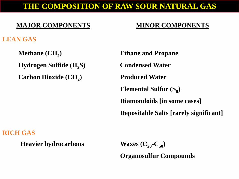
THE COMPOSITION OF RAW SOUR NATURAL GAS
MAJOR COMPONENTS
Methane (CH4)
Hydrogen Sulfide (H2S)
Carbon Dioxide (CO2)
MINOR COMPONENTS
LEAN GAS
Ethane and Propane
Condensed Water
Produced Water
Elemental Sulfur (S8)
Diamondoids [in some cases]
Depositable Salts [rarely significant]
RICH GAS
Heavier hydrocarbons Waxes (C20-C50)
Organosulfur Compounds
Page 3
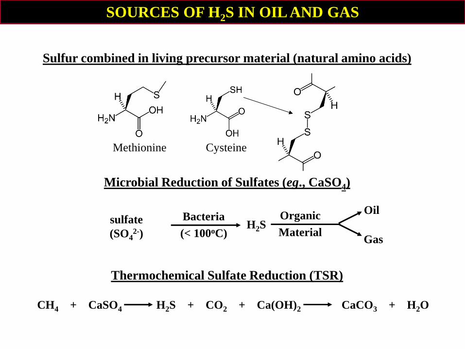
SOURCES OF H2S IN OIL AND GAS
Sulfur combined in living precursor material (natural amino acids)
Microbial Reduction of Sulfates (eg., CaSO4)
Thermochemical Sulfate Reduction (TSR)
sulfate
(SO42-)
Bacteria
(< 100oC) H2S
Organic
Material
Oil
Gas
Methionine Cysteine
CH4 + CaSO4 H2S + CO2 + Ca(OH)2 CaCO3 + H2O
Page 4
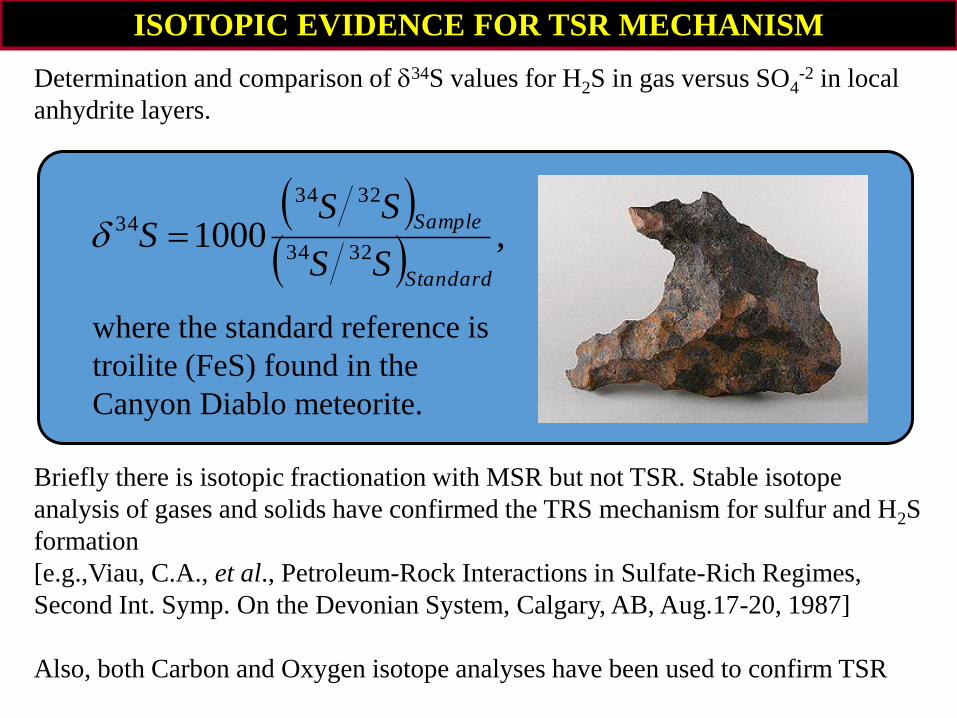
ISOTOPIC EVIDENCE FOR TSR MECHANISM
Determination and comparison of 34S values for H2S in gas versus SO4-2 in local
anhydrite layers.
Briefly there is isotopic fractionation with MSR but not TSR. Stable isotope
analysis of gases and solids have confirmed the TRS mechanism for sulfur and H2S
formation
[e.g.,Viau, C.A., et al., Petroleum-Rock Interactions in Sulfate-Rich Regimes,
Second Int. Symp. On the Devonian System, Calgary, AB, Aug.17-20, 1987]
Also, both Carbon and Oxygen isotope analyses have been used to confirm TSR
,10003234
3234
34
Standard
Sample
SS
SSS
where the standard reference is
troilite (FeS) found in the
Canyon Diablo meteorite.
Page 5
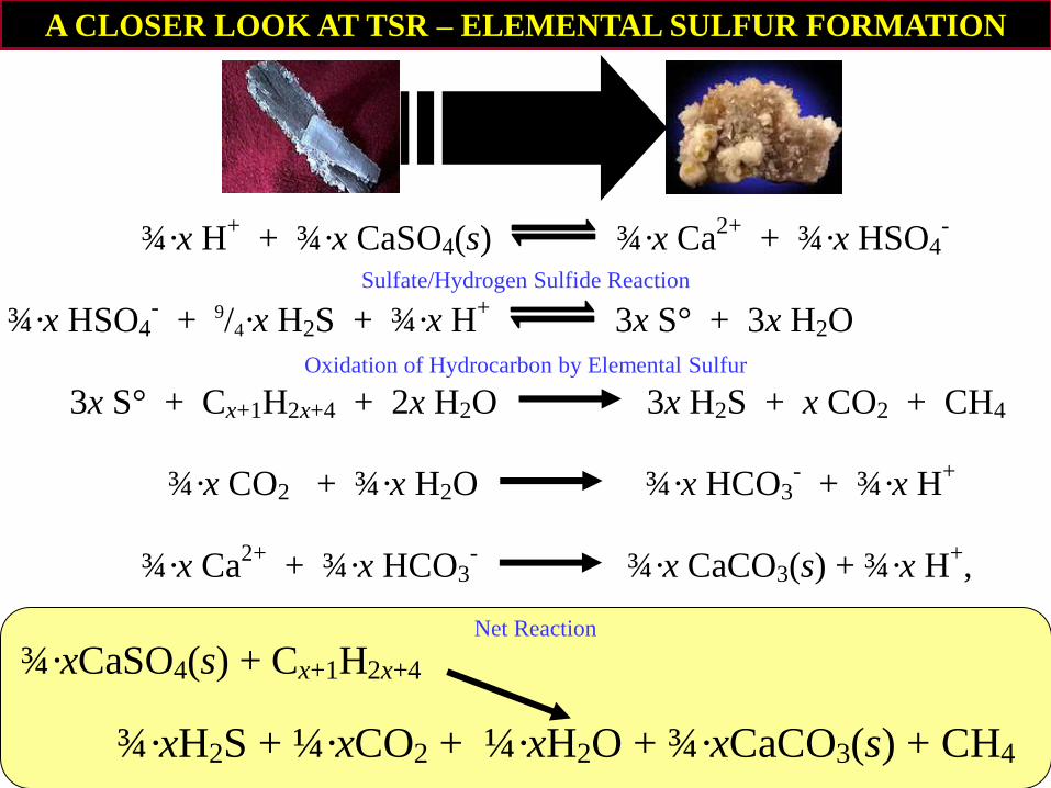
A CLOSER LOOK AT TSR – ELEMENTAL SULFUR FORMATION
¾·x H+ + ¾·x CaSO4(s) ¾·x Ca
2+ + ¾·x HSO4
- (5)
¾·x HSO4- + 9/4·x H2S + ¾·x H
+ 3x S° + 3x H2O (6)
3x S° + Cx+1H2x+4 + 2x H2O 3x H2S + x CO2 + CH4 (7)
¾·x CO2 + ¾·x H2O ¾·x HCO3- + ¾·x H
+ (8)
¾·x Ca2+
+ ¾·x HCO3- ¾·x CaCO3(s) + ¾·x H
+, (9)
Net Reaction
Sulfate/Hydrogen Sulfide Reaction
Oxidation of Hydrocarbon by Elemental Sulfur
¾·xCaSO4(s) + Cx+1H2x+4 ¾·xH2S + ¼·xCO2 + ¼·xH2O + ¾·xCaCO3(s) + CH4
¾·xCaSO4(s) + Cx+1H2x+4 ¾·xH2S + ¼·xCO2 + ¼·xH2O + ¾·xCaCO3(s) + CH4
Page 6
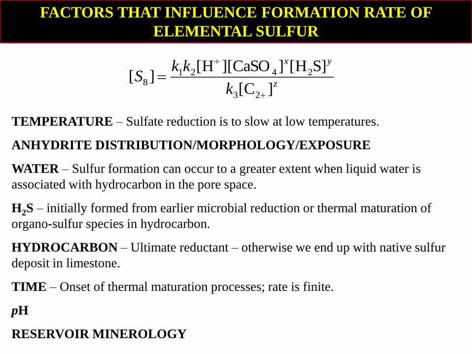
FACTORS THAT INFLUENCE FORMATION RATE OF
ELEMENTAL SULFUR
TEMPERATURE – Sulfate reduction is to slow at low temperatures.
ANHYDRITE DISTRIBUTION/MORPHOLOGY/EXPOSURE
WATER – Sulfur formation can occur to a greater extent when liquid water is
associated with hydrocarbon in the pore space.
H2S – initially formed from earlier microbial reduction or thermal maturation of
organo-sulfur species in hydrocarbon.
HYDROCARBON – Ultimate reductant – otherwise we end up with native sulfur
deposit in limestone.
TIME – Onset of thermal maturation processes; rate is finite.
pH
RESERVOIR MINEROLOGY
z
yx
k
kkS
]C[
]SH[]CaSO][H[][
23
24218
Page 7
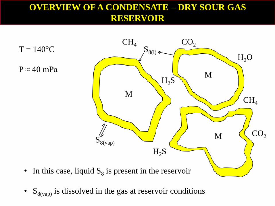
OVERVIEW OF A CONDENSATE – DRY SOUR GAS
RESERVOIR
• In this case, liquid S8 is present in the reservoir
• S8(vap) is dissolved in the gas at reservoir conditions
M
M
M
H2O
CH4
CO2
H2S
H2S
CO2 S8(l)
CH4
S8(vap)
T = 140°C
P ≈ 40 mPa
Page 8
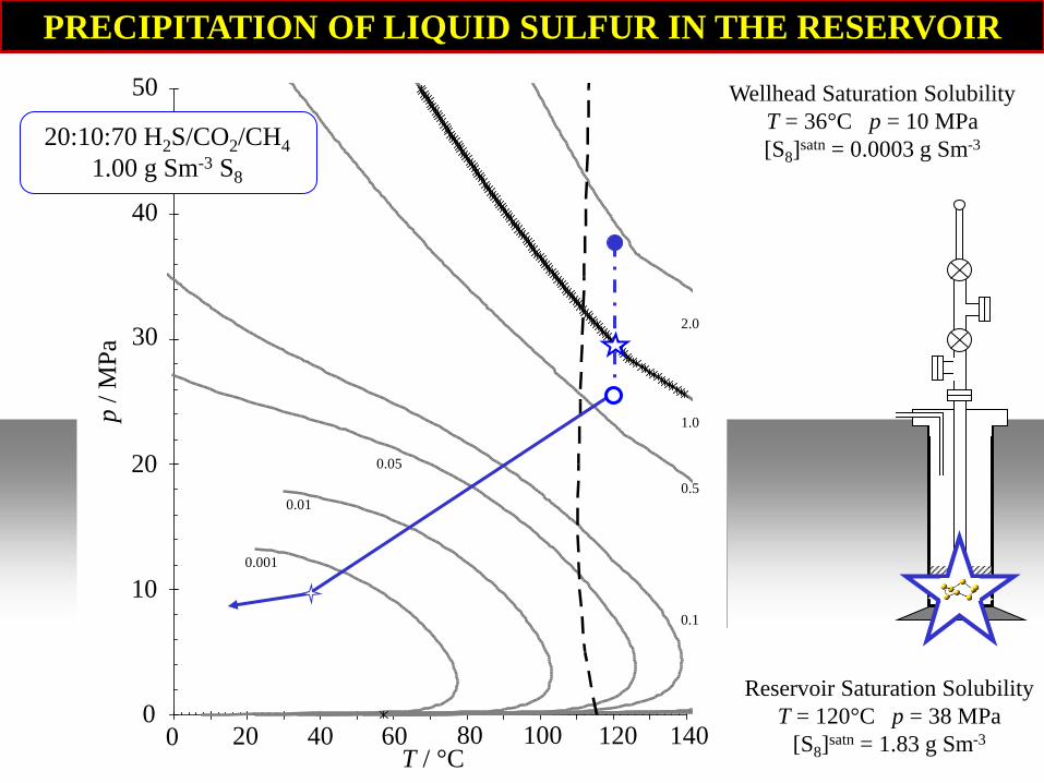
PRECIPITATION OF LIQUID SULFUR IN THE RESERVOIR
0.001
0.01
0.05
0.1
0.5
1.0
2.0
20:10:70 H2S/CO2/CH4
1.00 g Sm-3 S8
50
40
30
p /
MP
a
20
10
0 20 40 60
T / °C 80 100 120 140 0
Wellhead Saturation Solubility
T = 36°C p = 10 MPa
[S8]satn = 0.0003 g Sm-3
Reservoir Saturation Solubility
T = 120°C p = 38 MPa
[S8]satn = 1.83 g Sm-3
Page 9
0.001
0.01
0.05
0.1
0.5
1.0
2.0
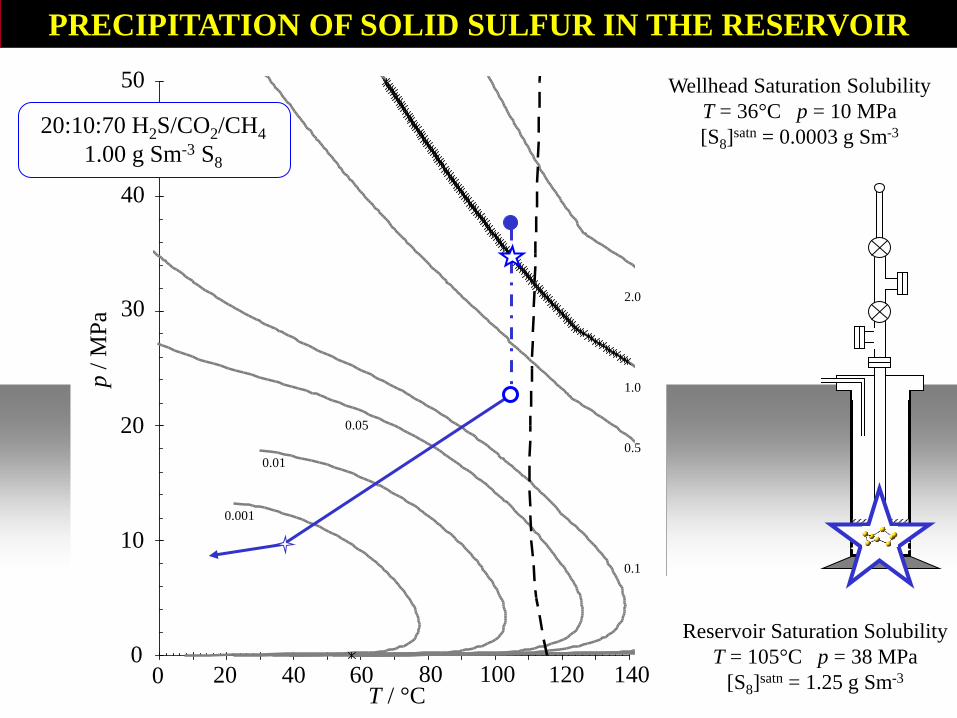
20:10:70 H2S/CO2/CH4
1.00 g Sm-3 S8
50
40
30
p /
MP
a
20
10
0 20 40 60
T / °C 80 100 120 140 0
Wellhead Saturation Solubility
T = 36°C p = 10 MPa
[S8]satn = 0.0003 g Sm-3
Reservoir Saturation Solubility
T = 105°C p = 38 MPa
[S8]satn = 1.25 g Sm-3
PRECIPITATION OF SOLID SULFUR IN THE RESERVOIR
Page 10
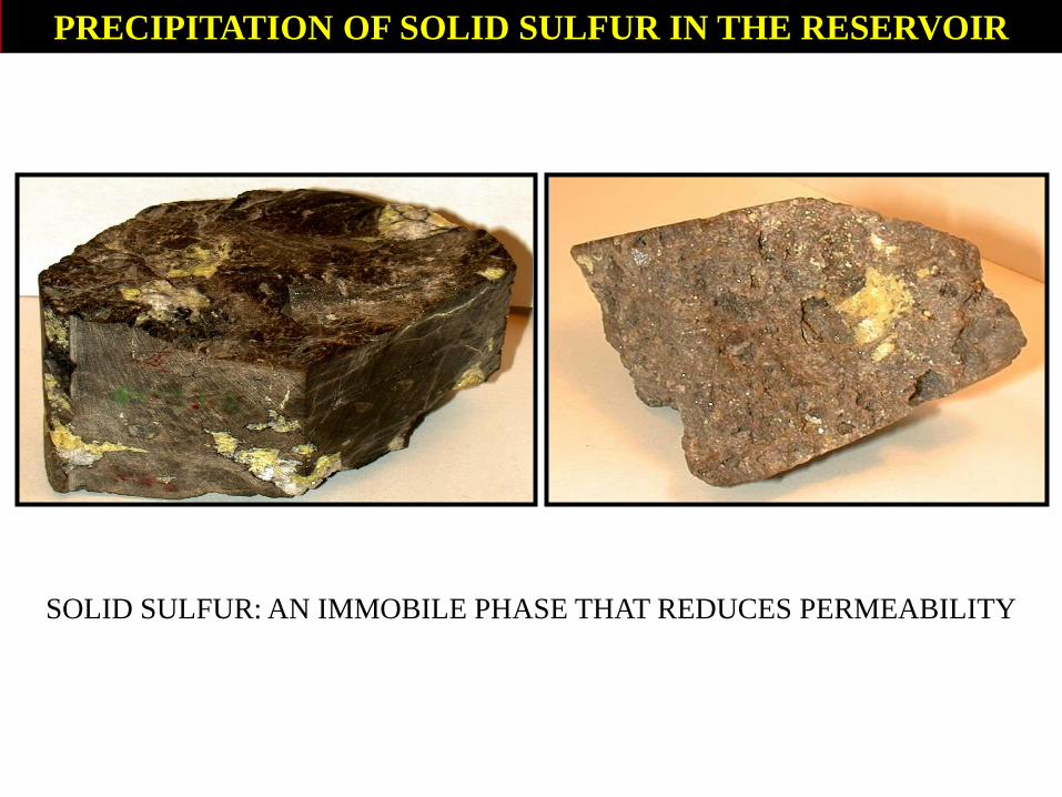
PRECIPITATION OF SOLID SULFUR IN THE RESERVOIR
SOLID SULFUR: AN IMMOBILE PHASE THAT REDUCES PERMEABILITY
Page 11
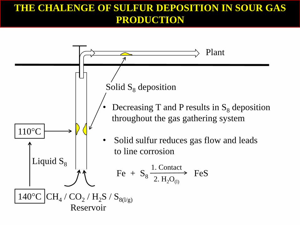
THE CHALENGE OF SULFUR DEPOSITION IN SOUR GAS
PRODUCTION
• Decreasing T and P results in S8 deposition
throughout the gas gathering system
• Solid sulfur reduces gas flow and leads
to line corrosion
Fe + S8 FeS
Plant
CH4 / CO2 / H2S / S8(l/g)
Reservoir
140°C
110°C
Liquid S8
Solid S8 deposition
1. Contact
2. H2O(l)
Page 12
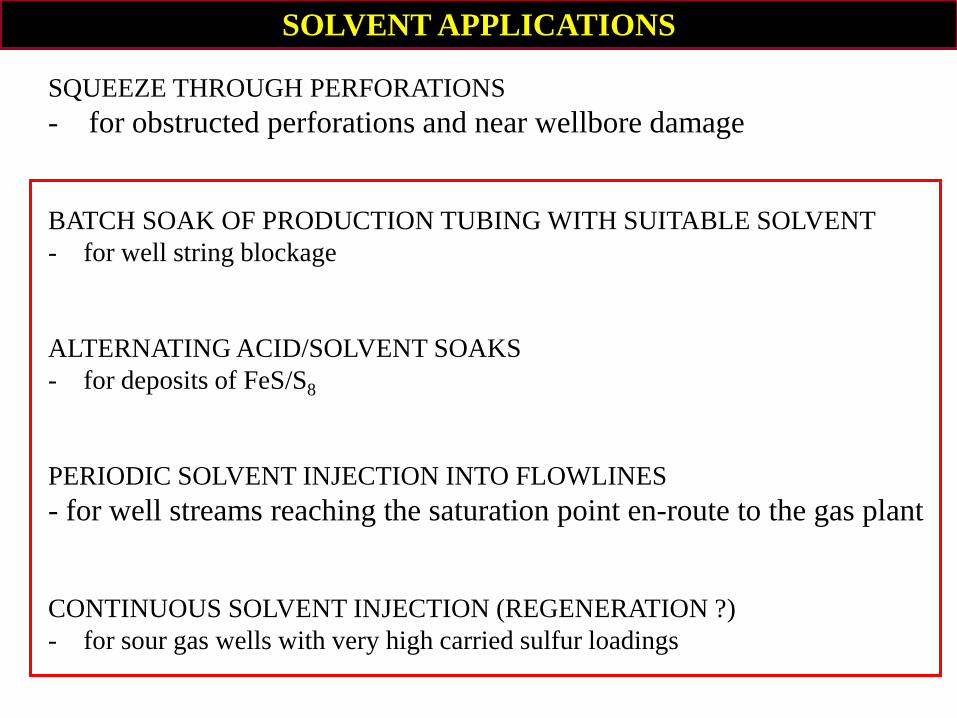
SQUEEZE THROUGH PERFORATIONS
- for obstructed perforations and near wellbore damage
BATCH SOAK OF PRODUCTION TUBING WITH SUITABLE SOLVENT
- for well string blockage
ALTERNATING ACID/SOLVENT SOAKS
- for deposits of FeS/S8
PERIODIC SOLVENT INJECTION INTO FLOWLINES
- for well streams reaching the saturation point en-route to the gas plant
CONTINUOUS SOLVENT INJECTION (REGENERATION ?)
- for sour gas wells with very high carried sulfur loadings
SOLVENT APPLICATIONS
Page 13
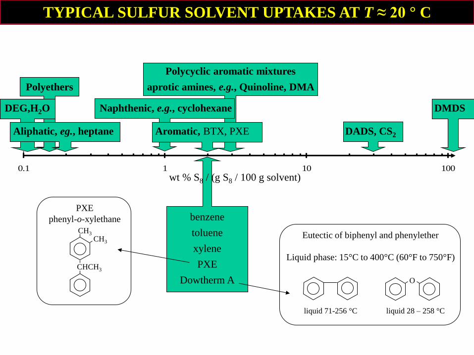
wt % S8 / (g S8 / 100 g solvent)
0
0.01
0.02
0.03
0.04
0.05
0.06
0.07
0.08
0.09
0.1
0.1 1 10 100
Polycyclic aromatic mixtures
Polyethers aprotic amines, e.g., Quinoline, DMA
Aliphatic, eg., heptane Aromatic, BTX, PXE DADS, CS2
TYPICAL SULFUR SOLVENT UPTAKES AT T ≈ 20 ° C
benzene
toluene
xylene
PXE
Dowtherm A
PXE
phenyl-o-xylethane
CHCH3
CH3
CH3 Eutectic of biphenyl and phenylether
Liquid phase: 15°C to 400°C (60°F to 750°F)
liquid 71-256 °C liquid 28 – 258 °C
O
DEG,H2O Naphthenic, e.g., cyclohexane DMDS
Page 14
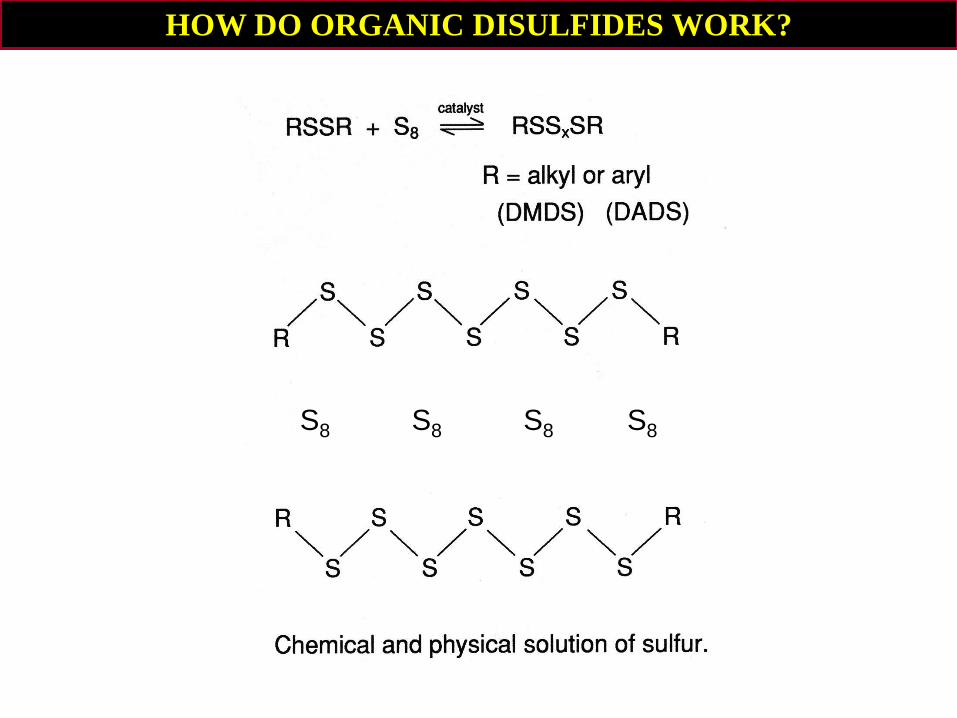
HOW DO ORGANIC DISULFIDES WORK?
S8 S8 S8 S8
Page 15
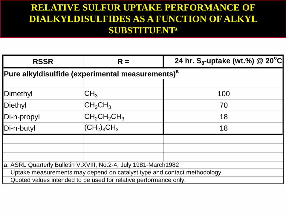
RELATIVE SULFUR UPTAKE PERFORMANCE OF
DIALKYLDISULFIDES AS A FUNCTION OF ALKYL
SUBSTITUENTa
RSSR R = 24 hr. S8-uptake (wt.%) @ 20oC
Pure alkyldisulfide (experimental measurements)a
Dimethyl CH3 100
Diethyl CH2CH3 70
Di-n-propyl CH2CH2CH3 18
Di-n-butyl (CH2)3CH3 18
a. ASRL Quarterly Bulletin V.XVIII, No.2-4, July 1981-March1982
Uptake measurements may depend on catalyst type and contact methodology.
Quoted values intended to be used for relative performance only.
Page 16
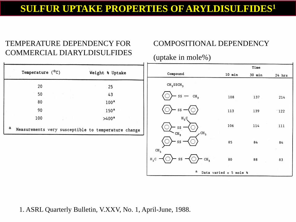
SULFUR UPTAKE PROPERTIES OF ARYLDISULFIDES1
TEMPERATURE DEPENDENCY FOR
COMMERCIAL DIARYLDISULFIDES
COMPOSITIONAL DEPENDENCY
(uptake in mole%)
1. ASRL Quarterly Bulletin, V.XXV, No. 1, April-June, 1988.
Page 17
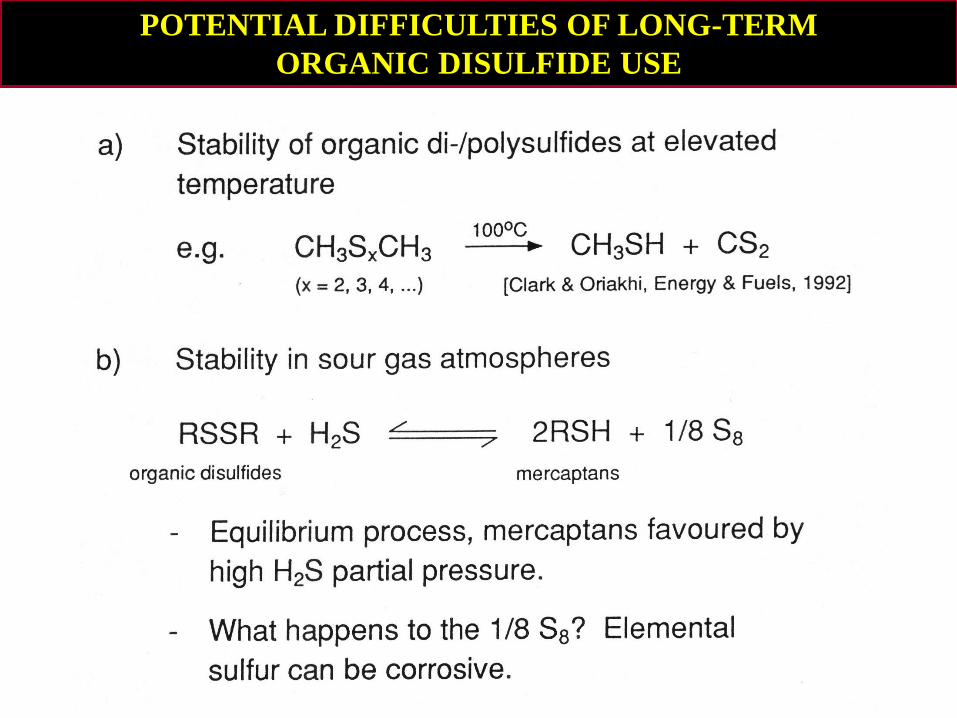
POTENTIAL DIFFICULTIES OF LONG-TERM
ORGANIC DISULFIDE USE
Page 18
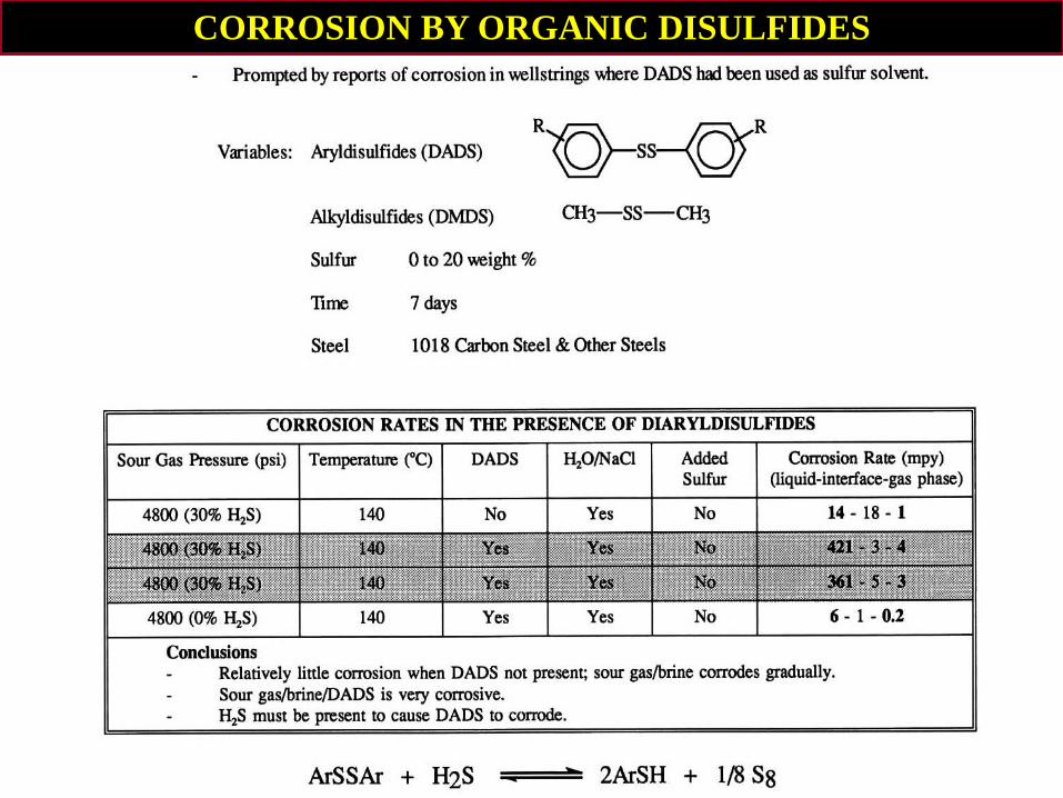
CORROSION BY ORGANIC DISULFIDES
Page 19
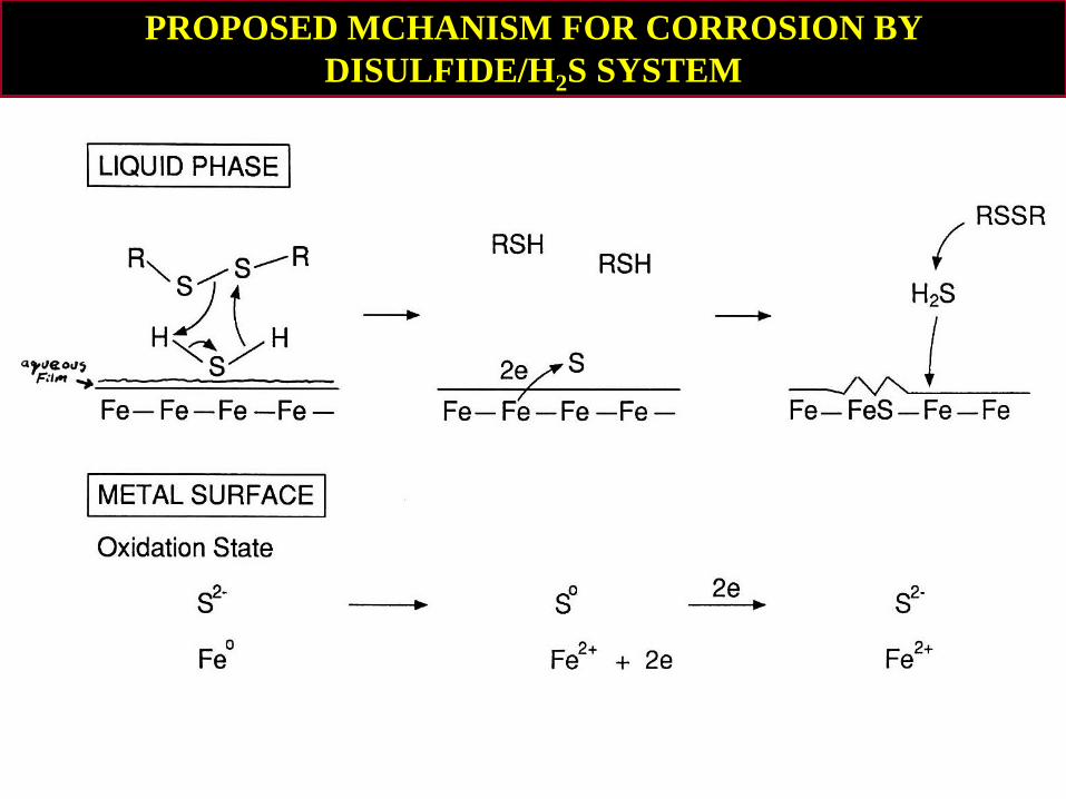
PROPOSED MCHANISM FOR CORROSION BY
DISULFIDE/H2S SYSTEM
Page 20
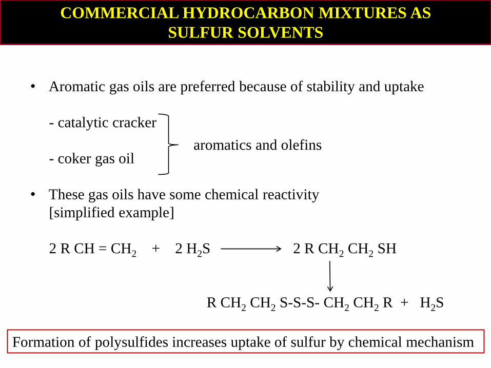
COMMERCIAL HYDROCARBON MIXTURES AS
SULFUR SOLVENTS
• Aromatic gas oils are preferred because of stability and uptake
- catalytic cracker
- coker gas oil
• These gas oils have some chemical reactivity
[simplified example]
2 R CH = CH2 + 2 H2S 2 R CH2 CH2 SH
R CH2 CH2 S-S-S- CH2 CH2 R + H2S
Formation of polysulfides increases uptake of sulfur by chemical mechanism
aromatics and olefins
Page 21
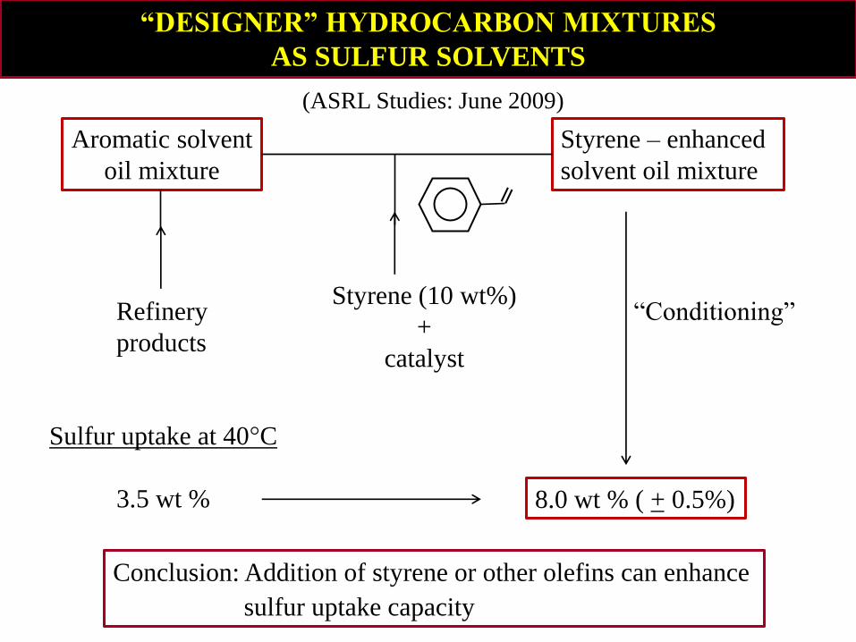
“DESIGNER” HYDROCARBON MIXTURES
AS SULFUR SOLVENTS
Aromatic solvent
oil mixture
Styrene – enhanced
solvent oil mixture
Refinery
products
Styrene (10 wt%)
+
catalyst
“Conditioning”
8.0 wt % ( + 0.5%) _
Sulfur uptake at 40°C
3.5 wt %
Conclusion: Addition of styrene or other olefins can enhance
sulfur uptake capacity
(ASRL Studies: June 2009)
Page 22
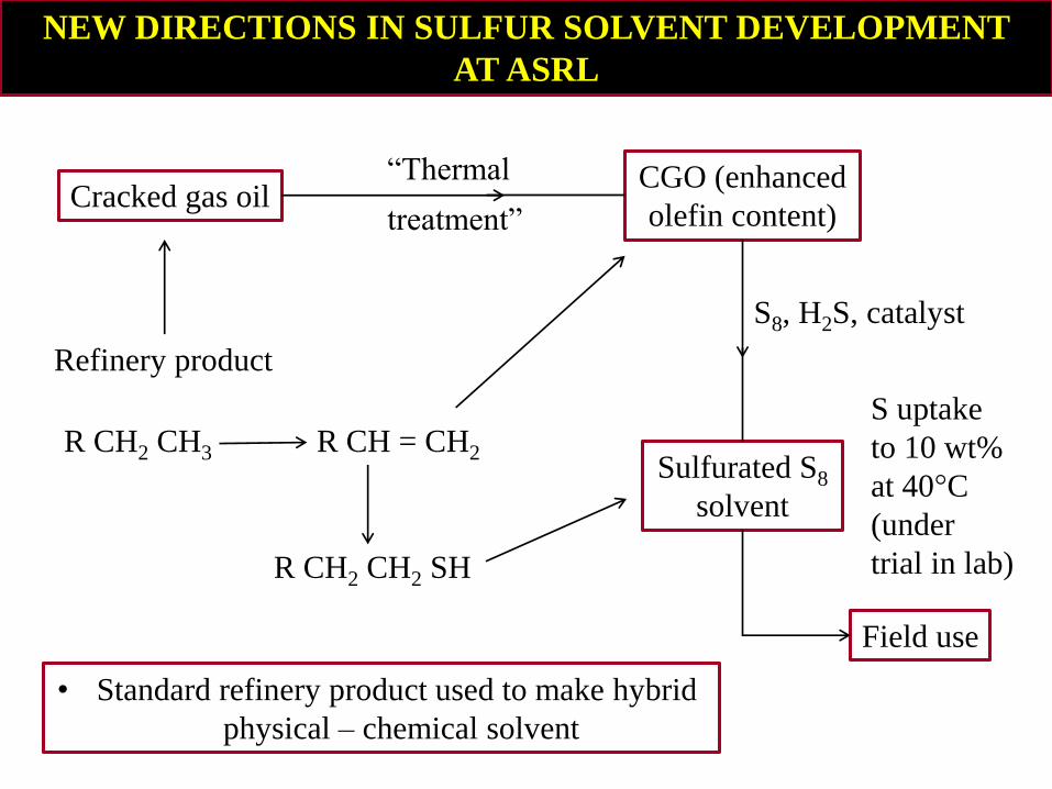
NEW DIRECTIONS IN SULFUR SOLVENT DEVELOPMENT
AT ASRL
Cracked gas oil CGO (enhanced
olefin content)
Sulfurated S8
solvent
Field use
• Standard refinery product used to make hybrid
physical – chemical solvent
S uptake
to 10 wt%
at 40°C
(under
trial in lab)
“Thermal
treatment”
S8, H2S, catalyst
Refinery product
R CH2 CH3 R CH = CH2
R CH2 CH2 SH
Page 23
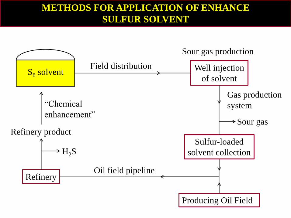
METHODS FOR APPLICATION OF ENHANCE
SULFUR SOLVENT
Refinery
Producing Oil Field
Sulfur-loaded
solvent collection
Well injection
of solvent
Refinery product
S8 solvent
Sour gas production
Gas production
system
Sour gas
“Chemical
enhancement”
H2S
Oil field pipeline
Field distribution
Page 24
ASRL MEMBER COMPANIES 2015 - 2016
Aecom Technology Corporation
Air Liquide Global E&C Solutions / Lurgi
Ametek Process & Analytical Instruments/Controls Southeast
AXENS
Baker Hughes
BASF Catalysts LLC
Bechtel Corporation
Black & Veatch Corporation
Brimstone STS Ltd.
Canadian Energy Services/PureChem Services - Canwell
ConocoPhillips Company
Enviro-Industries Ltd.
CB&I
Chevron Energy Technology Company
Denbury Resources Inc.
Devco
Duiker CE
E.I. du Pont Canada Company / MECS Inc.
EnCana Corporation
Enersul Inc.
Euro Support BV
ExxonMobil Upstream Research Company
Flint Hills Resources
Fluor Corporation / GAA
HEC Technologies
Husky Energy Inc.
IPAC Chemicals Limited
Jacobs Canada lnc. / Jacobs Nederland B.V.
KT – Kinetics Technology S.p.A.
Linde Gas and Engineering (BOC)
M I SWACO
Nalco Champion
OMV Exploration and Production GmbH
Optimized Gas Treating, Inc.
Ortloff Engineers, Ltd.
Oxbow Sulphur Canada ULC. (former ICEC)
Petro China Southwest Oil and Gas Field Company/RINGT
Phillips 66 Company
Porocel Industries, LLC
Prosernat
Riverland Industries Ltd.
Sandvik Process Systems, Inc./ Brimrock Group Inc.
Saudi Arabian Oil Company (Saudi Aramco)ASC
SemCAMS ULC
Shell Canada Energy
SiiRTEC Nigi S.p.A.
Sinopec / Pugaung Branch Company
Sulfur Recovery Engineering (SRE)
Sulphur Experts Inc. (Western Research)
Suncor Energy Inc.
TECHNIP
The Petroleum Institute / Abu Dhabi National
Oil Company (ADNOC)
Total S.A.
UniverSUL Consulting
Weatherford International LLC/ICTC
WorleyParsons
Page 25
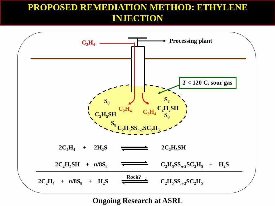
2C2H4 + 2H2S 2C2H5SH
2C2H5SH + n/8S8 C2H5SSn-2SC2H5 + H2S
2C2H4 + n/8S8 + H2S C2H5SSn-2SC2H5
Rock?
S8 S8
S8
S8
C2H4 Processing plant
PROPOSED REMEDIATION METHOD: ETHYLENE
INJECTION
T < 120°C, sour gas
C2H5SSn-2SC2H5
C2H5SH
C2H5SH C2H4 C2H4
Ongoing Research at ASRL