Overview Sultan Acoustic Wave Series A Higher Level of Performance Sultan Acoustic Wave Series Machinery Positioning Systems Data Sheet www.hawkmeasure.com For more information, please visit >
Transcript
OverviewSultan Acoustic Wave Series
A Higher Level of Performance
SultanAcoustic Wave Series Machinery Positioning Systems
Data Sheet
www.hawkmeasure.comFor more information, please visit >
The Sultan for Machinery Positioning systems consists of two systems. One is a standard Sultan programmed to ‘Position’ mode, the other is a special Sultan Slave system (software option PS). One system is generally mounted on moving machinery and the other at a fixed location. The ‘Master’ pulses are detected by a ‘Slave’ transducer which immediately emits a pulse back to the Master. The Master transmitter calculates transit times and provides an output proportional to the position of the moving machinery in relation to the Slaves fixed position. There is NO wiring requirement between the ‘Master’ and ‘Slave’ transducers, which allows for easy retrofit to existing shuttle conveyors, cranes, stackers, reclaimers, etc.
Dust, background noise, wet atmosphere, high winds can be compensated for by proper selection of operating frequency of the transducer e.g. use lower frequency transducers where high dust, high wind conditions prevail.
Function
The Sultan series includes a product range specifically designed for machine position sensing. Such a system is typically used to provide a signal representing the linear position of a moving machine to a control system.
• Self Cleaning sensor face requires no maintenance.
Features
• Non contact measurement• Range to 195m (640ft)• Wide range of communications: DeviceNet, GosHawk, HART, Modbus, Profibus DP, Foundation Fieldbus & Profibus PA
• Auto compensation for dust, steam and losses • Protection class IP67, NEMA 4x (IP68 Transducer)• Programmable fail safe mode• 3G remote setup options / configuration
OverviewSultan Acoustic Wave Series
3
Overview
Typical ApplicationsSultan Acoustic Wave Series
Shuttle Conveyors
Bunker Discharge Wagons
Stacker / ReclaimersMax. 195 metres
Max. 195 metres
Max. 195 metres
Max. 195 metres
Max. 195 metres
Max. 195 metres
Max. 195 metres
Max. 195 metres
Max. 195 metres
4
Overview
Typical ApplicationsSultan Acoustic Wave Series
OverviewSultan Acoustic Wave Series
5
Overview
DimensionsSultan Acoustic Wave Series
All cones must protrude into the main volume of the vessel by at least 50 mm (2 inches) past the lower end of the mounting nozzle.
Flanges
3 x M16Conduitentries
A
C
B
160mm (6.3”)
SeeFlangeTable
53.5mm (2.1")
305m
m (1
2”)
80m
m
(3.1
”)
75m
m
(2.9
”)
2" BSP or NPT THD
110mm (4.3”)1" BSP/NPT Nipple
B
SeeFlangeTable
A
D
80m
m
(3.1
”)~8
0mm
(3.1
”)
53.5mm (2.1")
Standard Type Compact Type (2”BSP / NPT) Standard Type
Integral Units Remote Transducers
Compact Type (2”BSP / NPT)
FLANGE TYPE:A = ANSI FlangeJ = JIS FlangeD = DIN Flange
H
E FG
Note: Other flange sizes available upon request.
STANDARD ANSI/DIN/JIS FLANGE DIMENSIONSFLANGETYPE
E (PCD) F (OD) G (ID) H (Hole)mm in. mm in. mm in. mm in.
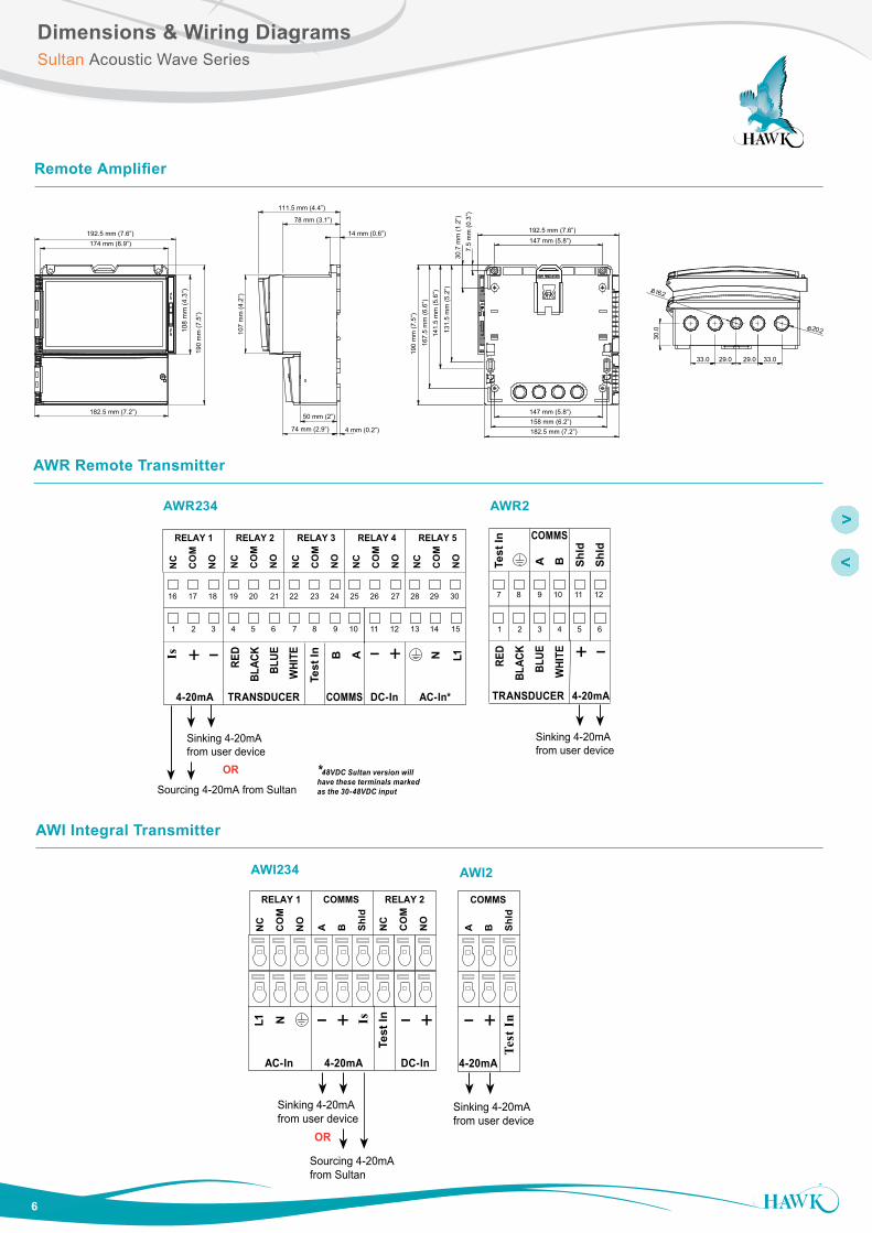
Dimensions & Wiring DiagramsSultan Acoustic Wave Series
Remote Amplifier
14 mm (0.6”)
74 mm (2.9”)
78 mm (3.1”)
107
mm
(4.2
”)
111.5 mm (4.4”)
4 mm (0.2”)
50 mm (2”)
131.
5 m
m (5
.2”)
7.5
mm
(0.3
”)
192.5 mm (7.6”)
141.
5 m
m (5
.6”)
190
mm
(7.5
”)
182.5 mm (7.2”)
147 mm (5.8”)16
7.5
mm
(6.6
”)
147 mm (5.8”)
30.7
mm
(1.2
”)
158 mm (6.2”)
108
mm
(4.3
”)
190
mm
(7.5
”)
174 mm (6.9”)192.5 mm (7.6”)
182.5 mm (7.2”)
30.0 20.2
33.029.029.033.0
16.2
AWI2
AWI Integral Transmitter
AWR Remote Transmitter
Sourcing 4-20mA from Sultan
Sinking 4-20mA from user device OR
+ – A 1L+– NB
RED
BLAC
K
BLUE
WHI
TE
Test
InIs
TRANSDUCER DC-In AC-In*4-20mA COMMS
RELAY 1
NC
CO
M
NO
RELAY 2
NC
CO
M
NO
RELAY 3
NC
CO
M
NO
RELAY 4
NC
CO
M
NO
RELAY 5
NC
CO
M
NO
1 2 3 4 5 6 7 8 9 10 11 12 13 14 15
16 17 18 19 20 21 22 23 24 25 26 27 28 29 30
B
RED
BLAC
K
BLUE
WHI
TE
Test
In
TRANSDUCER
COMMS
+ –
4-20mA
A Shld
Shld
Sinking 4-20mA from user device
1 2 3 4 5 6
7 8 9 10 11 12
*48VDC Sultan version will have these terminals marked as the 30-48VDC input
AWR2AWR234
RELAY 1
NC
CO
M
NO
RELAY 2
NC
CO
M
NO
COMMS
A B Shld
DC-In
+–
Test
In
4-20mA
Is1L N +–
AC-In
COMMS
A B Shld
+–
4-20mA
Test
In
Sourcing 4-20mA from Sultan
Sinking 4-20mA from user device OR
Sinking 4-20mA from user device
AWI234
7
Overview
MountingSultan Acoustic Wave Series
Mounting
The Transducer for both systems must be facing each other as accurately as possible. They must be completely level with the track as minor inclines or declines over long range can affect unit performance.
Avoid any flat reflective structure close to path between the Transducers as they will reflect acoustic energy and potentially cause erroneous readings. It is better to mount at a higher point to avoid track, rails, walkways etc.
Maintenance
If the Transducers are mounting horizontally, the Focalizer Cone may begin to fill with material in dusty environments. Monitor the Focalizer Cones over time and implement a cleaning schedule if required.
8
Overview
Setup InstructionSultan Acoustic Wave Series
Setup Instruction - ‘Master’ System
App Type (Quickset menu)
The ‘Master’ system is a standard Sultan Acoustic System programmed to ‘Position’ Application Type (App Type).The application speeds named Fill and Empty speed relate to the movement speed of the application. Fill is when the distance between the two systems is reducing, and Empty is the speed at which the distance is increasing.
The pre-set speed options are as follows (dependant on display Unit selection):
Fast 4000 metres / 13120 feet per hourMedium 2000 metres / 6560 feet per hourSlow 1000 metres / 3280 feet per hour
A ‘Custom’ value can also be programmed if there are any problems with the above pre-sets.
Hi / Lo Level (Quickset menu)
The Hi level represents the near distance (by default the 20mA reading). The Lo level indicates the far distance (by default 4mA reading). For low frequency transducers (15, 10, 9, 5, 4kHz) we recommend avoiding a Hi level of less than 3m (10ft).
Blanking (Advanced menu)
For safety margin, increase Blanking to 2.5m (however Blanking cannot be less than the High Level value).
Gain4 (Advanced menu)
Depending on application conditions the unit may need to be more sensitive to the return echoes from the Slave. To test this you should run the machine to the maximum range of the application and confirm the Slave system is pulsing. If the Slave system is not pulsing then this indicates it is not ‘hearing’ the Master. In order to choose the correct value, the Slave system should first be adjusted.
Setup Instruction - ‘Slave’ System
Gain4 (Advanced menu)
Continuing from the above, if at maximum required range the Slave system is not pulsing then Gain4% will need to be increased. Gain4 is located in the ‘Advanced’ menu. Increase Gain4 by 3% increments, pressing RUN to return the unit to operating mode with each increment to see if the unit responds. Once pulsing, increase by additional 3% for safety margin and note the Gain4 value. Return to the ‘Master’ system and input this value.
Blanking (Advanced menu)
For safety margin, increase Blanking to 2.5m.
System Re-start
After adjusting the above parameters, we recommend re-starting (power cycle) the Master system to allow it to begin functioning fresh with the adjusted parameters.
9
Overview
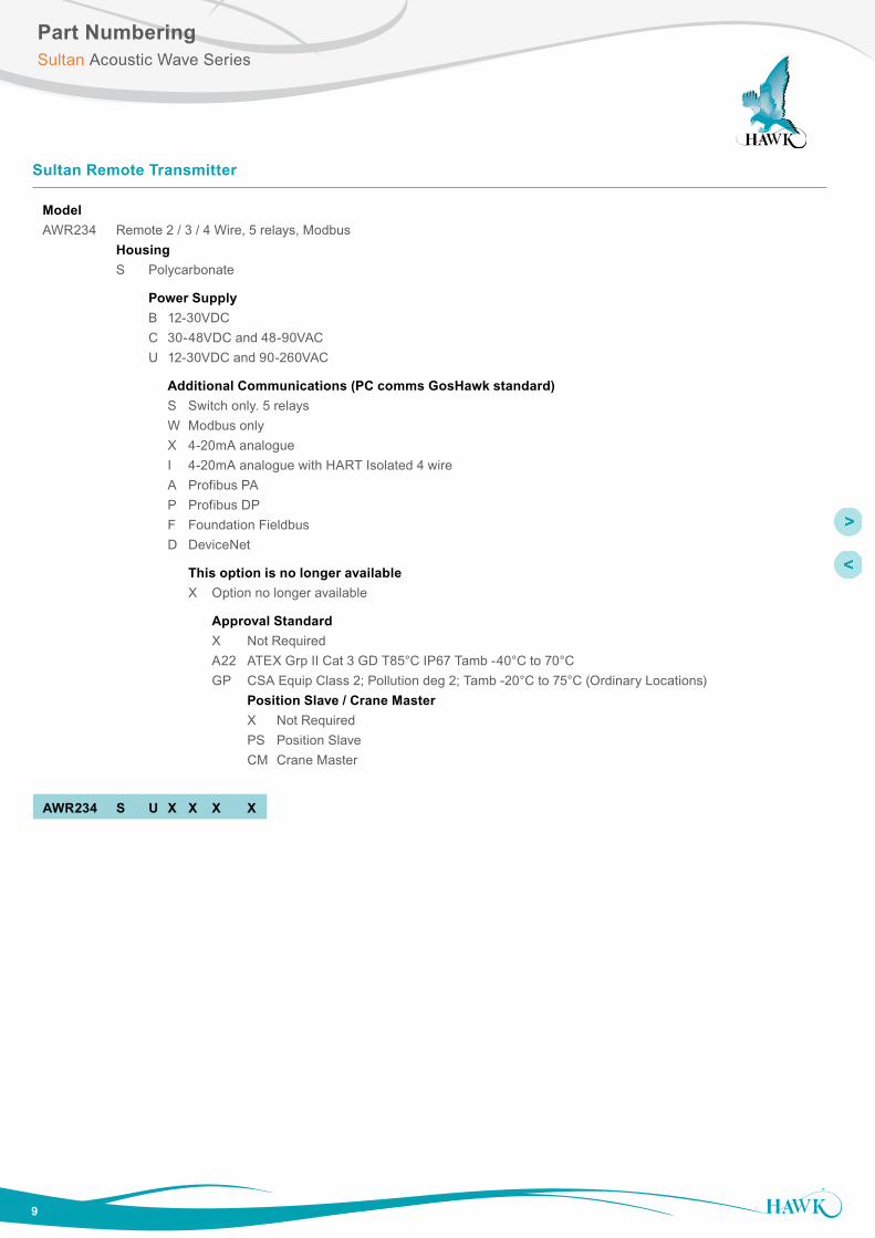
Part NumberingSultan Acoustic Wave Series
Model AWR234 Remote 2 / 3 / 4 Wire, 5 relays, Modbus Housing S Polycarbonate
Power Supply B 12-30VDC C 30-48VDC and 48-90VAC U 12-30VDC and 90-260VAC
Additional Communications (PC comms GosHawk standard) S Switch only. 5 relays W Modbus only X 4-20mA analogue I 4-20mA analogue with HART Isolated 4 wire A Profibus PA P Profibus DP F Foundation Fieldbus D DeviceNet
This option is no longer available X Option no longer available
Approval Standard X Not Required A22 ATEX Grp II Cat 3 GD T85°C IP67 Tamb -40°C to 70°C GP CSA Equip Class 2; Pollution deg 2; Tamb -20°C to 75°C (Ordinary Locations) Position Slave / Crane Master X Not Required PS Position Slave CM Crane Master
AWR234 S U X X X X
Sultan Remote Transmitter
10
Overview
Part NumberingSultan Acoustic Wave Series
Sultan Remote Transducer 3” and 3.5”
Model AWRT Acoustic Wave Remote Transducer
Transducer Frequency 30 30kHz for applications up to 15m for 3” (Cone required1) 20 20kHz for applications up to 20m, 3” only (Cone required1) 15 15kHz for applications up to 30m, 3” only (Cone required1) 10 10kHz for applications up to 40m, 3.5” only (Cone required1) 09 9kHz Positioning / Position Slave applications up to 195m (Cone required1) 05 5kHz for applications up to 60m, 3.5” only (Cone required1) 04 4kHz Positioning / Position Slave applications up to 195m (Cone required1)
Process Temperature - Facing material selection S2 Polyolefin 80°C (176°F) T3 Teflon 80°C (176°F) Y4 Titanium 80°C (176°F)
Transducer Housing Material 4 Polypropylene
Back Cap Mounting Thread Standards X Not Required (Standard Flange Mount) TB BSP
Back Cap Mounting Thread Sizes X Not Required (Standard Flange Mount) 305 3” BSP 506 3.5” BSP
Approval Standard X Not Required i0 IECEx Zone 0 Ex ia IIA T4 IP67 Tamb -20°C to 70°C A0 ATEX Grp II Cat 1 GD IP67 EEx ia IIA T4 i1 IECEx Zone 1 and 21 Ex mb II IP68 T5(Tamb -20°C to 65°C) T6(Tamb -20°C to 50°C) A1 ATEX Grp II Cat 2 GD EEx m II IP68 T5(Tamb -20°C to 65°C) T6(Tamb -20°C to 50°C) i20 IECEx Zone 20 DIP A20 TA85C IP68 Tamb -20°C to 75°C A20 ATEX Grp II Cat 1 D T85°C IP67 Tamb -20°C to 75°C A22 ATEX Dust (Grp II Cat 3 D T85C IP67) GP CSA Equip Class 2; Pollution deg 2; Tamb -20°C to 75°C (Ordinary Locations) RN CSA Class I; Div 1/2; Group D; Zone 0; AEx / Ex ia IIA; T4 KN CSA Class II; Div 2; Group F&G; Class III; T6 T85 for Tamb -20°C to 75°C QN CSA Class II; Div 1; Group E, F&G; Ex mb II; T5(T100) for Tamb -20°C to 65°C; T6(T85) for Tamb -20°C to 50°C
Mounting Accessories X Not Required CS6 End Cap Cable Suspension
Software Options X Not Required FP6 Fast Pulsing PS Position Slave (Requires Position Slave Amplifier)
AWRT 10 T 4 X X X C 6 X X
1 See Transducer / Cone / Flange combination table2 Transducer Frequency 04, 05, 09, 10 only3 Transducer Frequency 10, 15, 20, 30 only4 Transducer Frequency 15 only5 Transducer Frequency 15, 20, 30 only6 Transducer Frequency 04. 05, 09, 107 Transducer Frequency 30, 20 only
11
Overview
Part NumberingSultan Acoustic Wave Series
Model AWRT Acoustic Wave Remote Transducer
Transducer Frequency 50 50kHz for liquid applications up to 5m (Cone required1) 40 40kHz for liquid applications up to 7m (Cone required1) 30 30kHz for liquid applications up to 11m (Cone required1)
Process Temperature - Facing material selection T Tefzel 80°C (176°F)
Transducer Housing Material 6 Tefzel
Thread Standard TB BSP TN NPT
Thread Size 20 2” thread
Approval Standard X Not Required i0 IECEx Zone 0 Ex ia IIA T4 IP67 Tamb -20°C to 70°C A0 ATEX Grp II Cat 1 GD IP67 EEx ia IIA T4 i1 IECEx Zone 1 and 21 Ex mb II IP68 T5(Tamb -20°C to 65°C) T6(Tamb -20°C to 50°C) A1 ATEX Grp II Cat 2 GD EEx m II IP68 T5(Tamb -20°C to 65°C) T6 (Tamb -20°C to 50°C) i20 IECEx Zone 20 DIP A20 TA85C IP68 Tamb -20°C to 75°C A20 ATEX Grp II Cat 1 D T85°C IP67 Tamb -20°C to 75°C A22 ATEX Grp II Cat 3 GD T85°C IP67 Tamb -40°C to 70°C GP CSA Equip Class 2; Pollution deg 2; Tamb -20°C to 75°C (Ordinary Locations) RN CSA Class I; Div 1/2; Group D; Zone 0; AEx/Ex ia IIA; T4 KN CSA Class II; Div 2; Group F&G; Class III; T6 T85 for Tamb -20°C to 75°C QN CSA Class II; Div 1; Group E, F&G; Ex mb II; T5(T100) for Tamb -20°C to 65°C; T6(T85) for Tamb -20°C to 50°C
Connection C IP68 Sealed unit with cable Cable Length 6 6m cable 15 15m cable 30 30m cable 50 50m cable
Mounting Accessories X Not Required CS Cable Suspension on end cap
Software Options X Not Required PS Position Slave
AWRT 30 T 6 TB 20 X C 6 X X
Sultan Remote Transducer 2”
1 See ‘Transducer / Cone / Flange combination table
12
Overview
Model AWI234 Integral 2 / 3 / 4 Wire, 2 relays, Modbus
Housing S Valox 357U
Power Supply B 12-30VDC U 12-30VDC and 90-260VAC
Transducer Frequency 30 30kHz for applications up to 11m for 2” and 15m for 3” (Cone required6) 20 20kHz for applications up to 20m, available in 3” only (Cone required6) 15 15kHz for applications up to 30m, available in 3” only (Cone required6) 10 10kHz for applications up to 40m, available in 3.5” only (Cone required6) 09 9kHz for Positioning / Position Slave applications up to 180m (Cone required6) 05 5kHz for applications up to 60m, available in 3.5” only (Cone required6) 04 4kHz for Positioning / Position Slave applications up to 180m (Cone required6)
Process Temperature - Facing material selection S2 Polyolefin 80°C (176°F) T3 Teflon 80°C (176°F) Y4 Titanium 80°C (176°F)
Transducer Housing Material 4 Polypropylene
This option is no longer available X Option no longer available
This option is no longer available X Option no longer available
Additional Communication S Switch only. 2 relays W Modbus only X 4-20mA analogue I 4-20mA analogue with HART Isolated 4 wire A Profibus PA F Foundation Fieldbus
Approval Standard X Not Required A22 ATEX Grp II Cat 3 GD T85°C IP67 Tamb -40°C to 70°C
Software Options X Not Required PS Position Slave
AWI234 S U 10 S 4 X X X X X
Part NumberingSultan Acoustic Wave Series
Sultan Integral 3” and 3.5”
2 Transducer Frequency 04, 05, 09, 10 only3 Transducer Frequency 10, 15, 20, 30 only4 Transducer Frequency 15 only6 See Transducer / Cone / Flange combination table
13
Overview
Part NumberingSultan Acoustic Wave Series
Model AWI234 Integral 2 / 3 / 4 Wire, 2 relays, Modbus
Housing S Valox 357U
Power Supply B 12-30VDC U 12-30VDC and 90-260VAC
Transducer Frequency 50 50kHz for liquid applications up to 5m (Cone required6) 40 40kHz for liquid applications up to 7m (Cone required6) 30 30kHz for liquid applications up to 11m (Cone required6)
Process Temperature - Facing material selection T Tefzel 80°C (176°F)
Transducer Housing Material 6 Tefzel
Thread Standards TB BSP TN NPT
Mounting Thread Sizes 20 2” thread
Additional Communication S Switch only W Modbus only X 4-20mA analogue I 4-20mA analogue with HART Isolated 4 wire A Profibus PA F Foundation Fieldbus
Approval Standard X Not Required A22 ATEX Grp II Cat 3 GD T85°C IP67 Tamb -40°C to 70°C
Software Options X Not Required PS Position Slave
AWI234 S U 40 T 6 TB 20 X X X
Sultan Integral 2”
6 See Transducer / Cone / Flange combination table
14
Overview
Part NumberingSultan Acoustic Wave Series
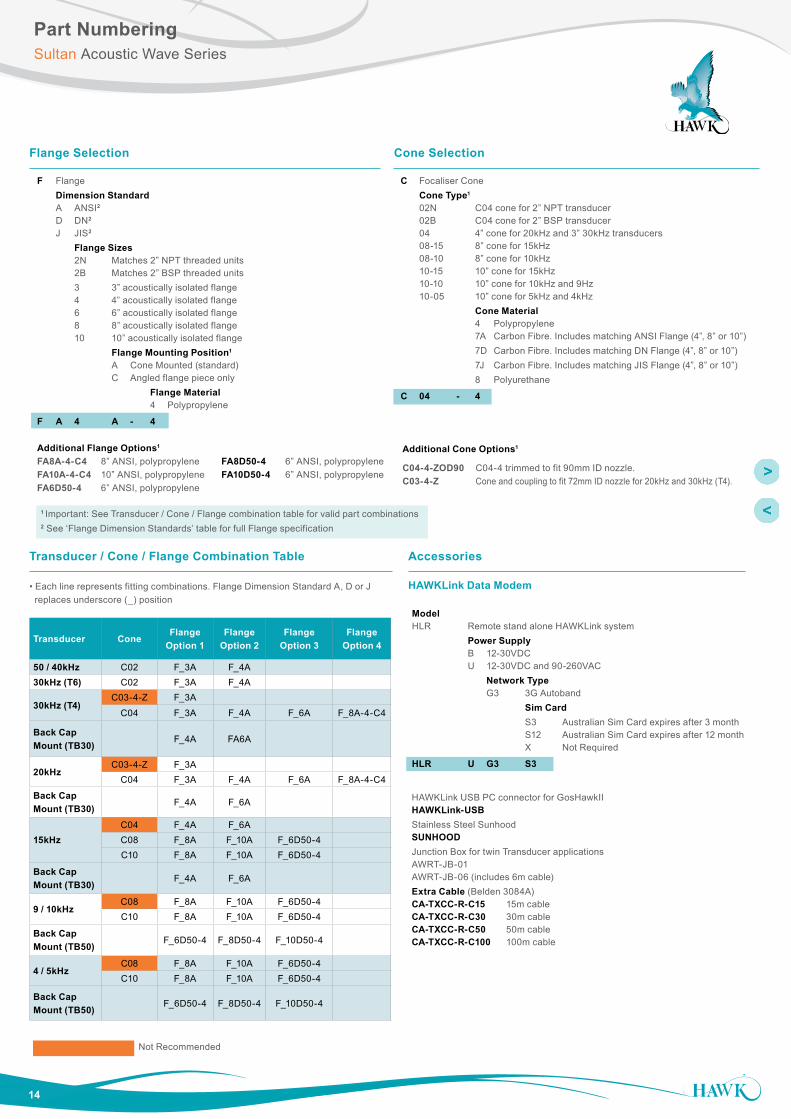
Flange Selection
F Flange Dimension Standard A ANSI2 D DN2 J JIS2
Flange Sizes 2N Matches 2” NPT threaded units 2B Matches 2” BSP threaded units 3 3” acoustically isolated flange 4 4” acoustically isolated flange 6 6” acoustically isolated flange 8 8” acoustically isolated flange 10 10” acoustically isolated flange Flange Mounting Position1 A Cone Mounted (standard) C Angled flange piece only Flange Material 4 Polypropylene
F A 4 A - 4
Cone Selection
C Focaliser Cone Cone Type1 02N C04 cone for 2” NPT transducer 02B C04 cone for 2” BSP transducer 04 4” cone for 20kHz and 3” 30kHz transducers 08-15 8” cone for 15kHz 08-10 8” cone for 10kHz 10-15 10” cone for 15kHz 10-10 10” cone for 10kHz and 9Hz 10-05 10” cone for 5kHz and 4kHz Cone Material 4 Polypropylene 7A Carbon Fibre. Includes matching ANSI Flange (4”, 8” or 10”) 7D Carbon Fibre. Includes matching DN Flange (4”, 8” or 10”) 7J Carbon Fibre. Includes matching JIS Flange (4”, 8” or 10”) 8 Polyurethane
C 04 - 4
Model HLR Remote stand alone HAWKLink system Power Supply B 12-30VDC U 12-30VDC and 90-260VAC Network Type G3 3G Autoband Sim Card S3 Australian Sim Card expires after 3 month S12 Australian Sim Card expires after 12 month X Not Required
HLR U G3 S3
HAWKLink USB PC connector for GosHawkII HAWKLink-USBStainless Steel Sunhood SUNHOODJunction Box for twin Transducer applications AWRT-JB-01 AWRT-JB-06 (includes 6m cable)Extra Cable (Belden 3084A) CA-TXCC-R-C15 15m cable CA-TXCC-R-C30 30m cable CA-TXCC-R-C50 50m cable CA-TXCC-R-C100 100m cable
1 Important: See Transducer / Cone / Flange combination table for valid part combinations2 See ‘Flange Dimension Standards’ table for full Flange specification
OverviewSultan Acoustic Wave Series
Hawk Measurement Systems(Head Office)15 - 17 Maurice Court Nunawading VIC 3131, AUSTRALIA
For more information and global representatives: www.hawkmeasure.comAdditional product warranty and application guarantees upon request. Technical data subject to change without notice.
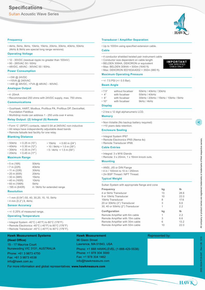
Frequency
• 4kHz, 5kHz, 9kHz, 10kHz, 15kHz, 20kHz, 30kHz, 40kHz, 50kHz (4kHz & 9kHz are special long range versions).
• GosHawk, HART, Modbus, Profibus PA, Profibus DP, DeviceNet, Foundation Fieldbus • Mulitidrop mode can address 1 - 250 units over 4 wires.
Relay Output: (2) Integral (5) Remote
• Form ‘C’ (SPDT) contacts, rated 0.5A at 240VAC non-inductive • All relays have independently adjustable dead bands • Remote failsafe test facility for one relay.
Blanking Distance
• 50kHz = 0.25 m (10”) • 40kHz = 0.30 m (12”) • 30kHz = 0.35 m (14”) • 20kHz = 0.45 m (17”)
Maximum Range
• 5 m (16ft) 50kHz • 7 m (22ft) 40kHz • 11 m (33ft) 30kHz • 20 m (65ft) 20kHz • 30 m (98ft) 15kHz • 40 m (165ft) 10kHz • 60 m (196ft) 5kHz • 195 m (640ft) 4 / 9kHz for extended range
Resolution
• 1 mm (0.04”) 50, 40, 30,20, 15, 10, 5kHz • 4 mm (0.2”) 9, 4kHz.
Sensor Accuracy
• +/- 0.25% of measured range.
Operating Temperature
• Integral System -40°C (-40°F) to 80°C (176°F) • Remote Electronics -40°C (-40°F) to 80°C (176°F) • Remote Transducer -40°C (-40°F) to 80°C (176°F).


![A higher level of performance - artronix.co.kr Data/catalog/Sultan_234P_Catalog_[eng].pdf · A higher level of performance Non contact position ... (CSA, FM pending) Sultan 2 Series](https://static.documents.pub/doc/80x56/5b77cc6c7f8b9ade6f8dbd42/a-higher-level-of-performance-datacatalogsultan234pcatalogengpdf-a.jpg)


