SULTANATE OF OMAN MINISTRY OF ELECTRICITY & WATER STANDARD - OES 32 DOUBLE CIRCUIT 132KV OVERHEAD TRANSMISSION LINE 400 SQ.MM ALL ALUMINIUM ALLOY TWIN CONDUCTORS ON LATTICE STEEL TOWERS FIRST EDITION JANUARY 1995
Transcript
SULTANATE OF OMAN
MINISTRY OF ELECTRICITY & WATER
STANDARD - OES 32
DOUBLE CIRCUIT 132KV OVERHEAD TRANSMISSION LINE 400 SQ.MM ALL ALUMINIUM ALLOY TWIN CONDUCTORS
Scope Une Conductors Earth Wire I Shield Wire Insulators Line Accessories Fittings Midspan Jomts, Dead Ends, Jumber, Termmals, Rep",r Sleeves Vibration Dampers Spacers Spacer Dampers Jumber Spacers Aircraft Wammg Spheres Aircraft Warning Ughts Armour Rods Arcing Horns Live Une Cleanmg Arrangement 132KV Towers and Foundations General DeSIgn Spans Types of Supports COnductor and Earthwrre Spacmg and Clearance Clearance to Ground and Other Features Assumed Normal Working Loadings Broken Wire Conditions Factors of Safety for Towers and FoundatIons Construction of Support Steel Work Foundations Aggresslvity of Soils to Bunw Concrete Concrete Anti-Climbing Guards and Climbing Steps Danger, Number and Phase Plates Support Structure Earthing Workmanship Aircraft Warnmg Pamting
Page
2 3 4
6
7 8
9
10 11
12
14 15
17 19
21 22
23 24
TABLE OF CONTENTS (CONTD ... )
Clause Description Page
6.0 Access, Cleanng and Erection 24
6.1 ConstructIOn Access to Site
6.2 Route and Access Clearance 25
6.3 Preliminary Survey
6.4 Alignment Survey
6.5 Profile Survey
6.6 Wayleaves 27
6.7 Crossmg of Public ServIces 28
6.8 Other Crossmgs
6.9 Livestocl<
6.10 Damage to Crops and Property 29
6.11 Removal of Obstructions
6.12 Foundations
6.13 ErectIOn of Supports 31
6.14 Erection of Conductors
6.15 Sags and TensIOns 33
7.0 Inspection and Testmg 34
7.1 Inspection and Testing Durmg Manufacture
7.1.1 Conductors 35
7.1.2 Earthwires
7.1.3 Insulators
7.1.4 Insulator Strmgs
7.1.5 Insulator and Earthwire Fittings 36
7.1.6 Tension Clamps and Jomts
7.1.7 Spacers - Overall Movements Tests
7.1.8 Supports 38
7.1.9 Galvamsmg 39
7.2 Tests at Site 40
7.2.1 Soil and Foundation Tests
7.2.2 Tests Durmg Erection 41
7.2.3 Tests on CompletIOn 42
7.2.4 Tests at End of Mamtenance Penod
SCHEDULES
TABLE OF CONTENTS
Schedules Description Page
SCh. I System Details
Sch.2 Temperature LimIts and Loadings 1
Sch. 3 Factors of Safety 2
SCh.4 Line Minimum Clearance 3
Sch. 5 Support ElectrIcal Clearance Design Data 4
SCh. 6 PartIculars of Conductors, Earthwlres and Dampers 5
SCh. 7 Particulars of Longrod Porcelam Aerofoil Insulators and Fittings 9
SCh.8 PartIculars of Support and FoundatIOn DeSIgn Data 12
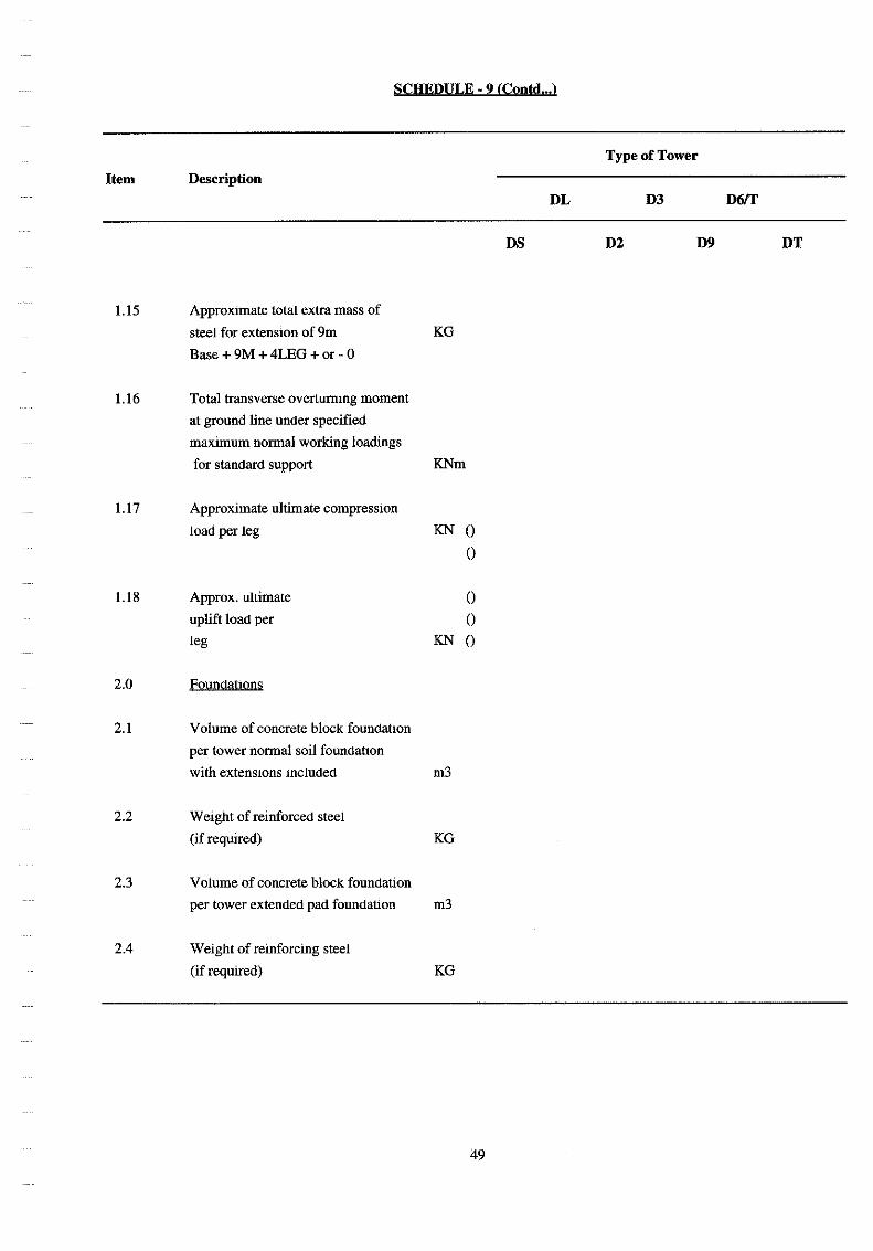
SCh.9 Particulars of Supports and Foundations 14
SCh.1O Dates for Manufacture, Completion and Testing 17
SCh. II Manufacturers and Places of Manufacture, Testing, Inspection and 19
Shipment and Standards
SCh. 12 Sub-Contractors 21
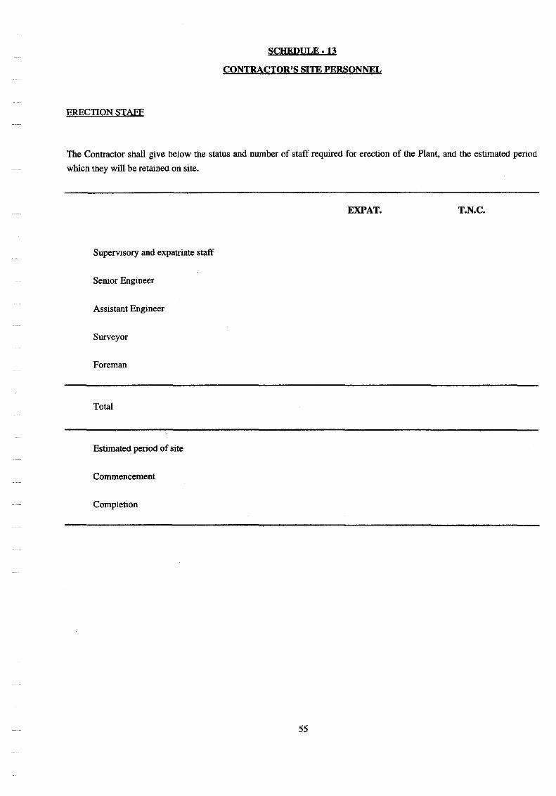
Sch. 13 Contractor's Site Personnel 22
SCh. 14 List of Contractor's Plant and Tools 23
SCh. 15 Departures from Requrrements of this SpecificatIOn 24
Sch. 16 Tenderer's Experience 25
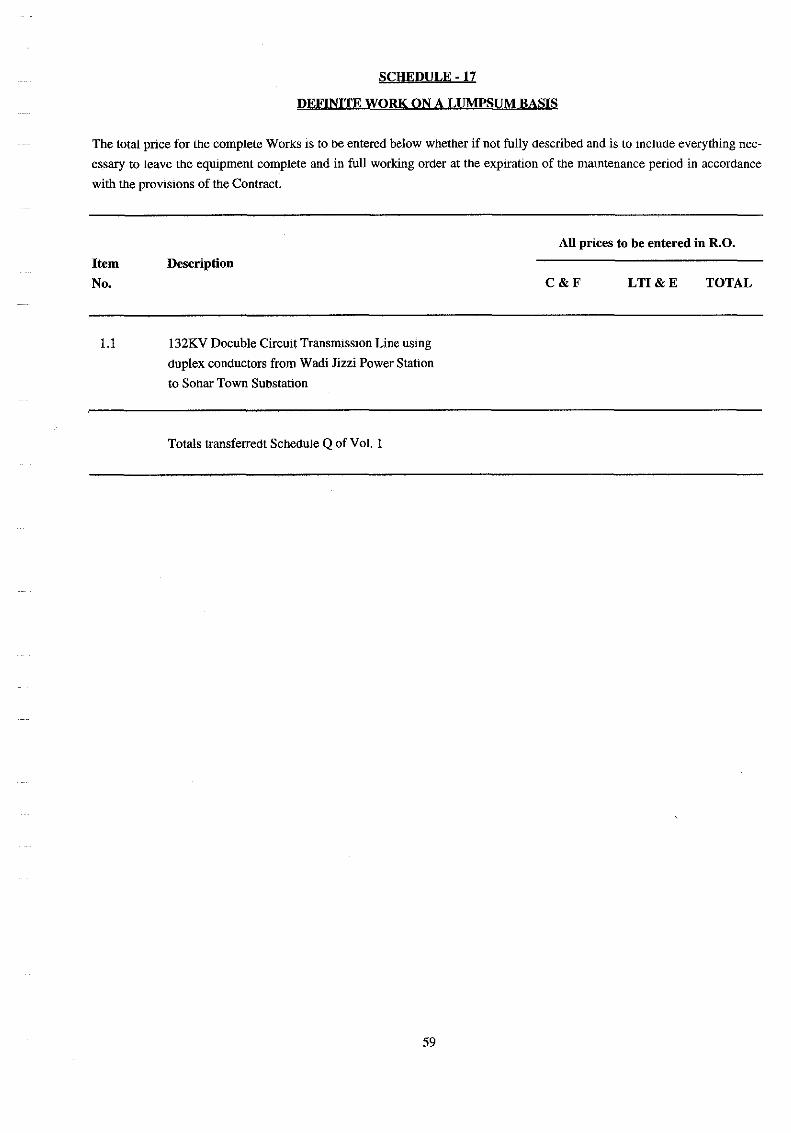
Sch. 17 Definite Work on a Lumpsum BaSIS 26
SCh. 18 Schedule of Rates for VarIation Overhead Lines 27
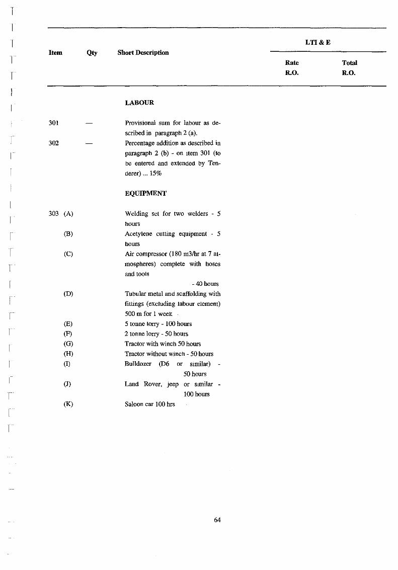
Sch. 19 Dayworks (ProvIsIonal) 28
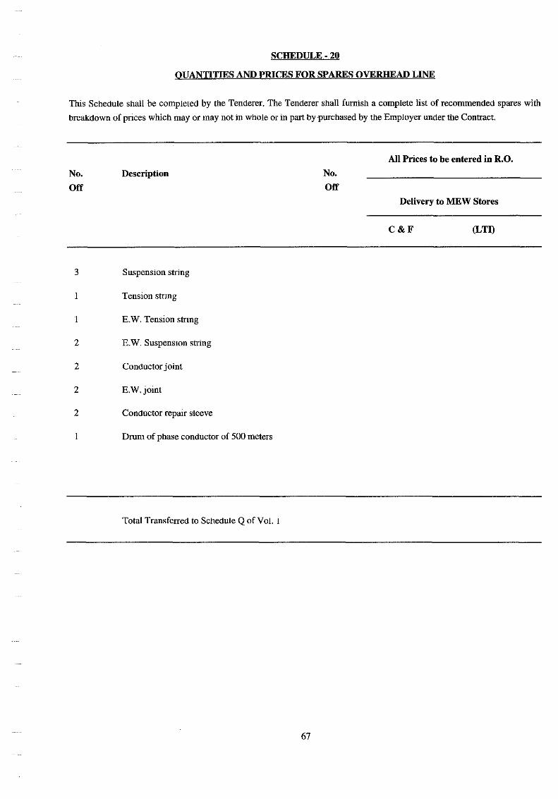
SCh.20 Quantities and Prices for Spares Overhead Lines 34
Sch. 21 Quantities and Prices for Mamtenance Tools and Appliances Overhead Lines 35
1.0 SCOPE
SULTANATE OF OMAN
MINISTRY OF ELECTRICITY & WATER
STANDARD OES ·32
DOUBLE CIRCUIT 132KV OVERHEAD TRANSMISSION LINE
400 SQ.MM ALL ALUMINIUM ALLOY TWIN CONDUCTORS
ON LATTICE STEEL TOWERS
The specification covers complete supply, erection and comrmsslOmng of 132 KV double clfcuit transmission line
on Lattice Steel towers with twm conductor 400 sq. mm all aluminium alloy conductor and shield conductor of alu
minium clad steel 7/3.26.
The scope of work Shall include the desIgn, manufacture, supply, testilig, mspection at manufacturer;s works, msu
rance, packing for export shipment, delivery to the SIte, unloading, survey and profile plotting of support position,
peggmg out, clearing and provision of access roads where necessary complete erection, settmg to work and mamte
nance for a period of 12 calendar months of the 132 KV double CIrCUlt line.
The scope also shall include all parts of work to be completed in every respect for commerCial operation to the sat
isfaction of MEW.
The three phase of each circuit are to be in vertical formation at suspensIOn position and a single over running earth
WIre.
The parameters and ratings of the 132 KV line shall be establiShed for a normal electncal load transfer of 300 MY A
through each CIfCUlt at 132 KV nominal VOltage m Oman climatic condition as mentioned in OES 11.
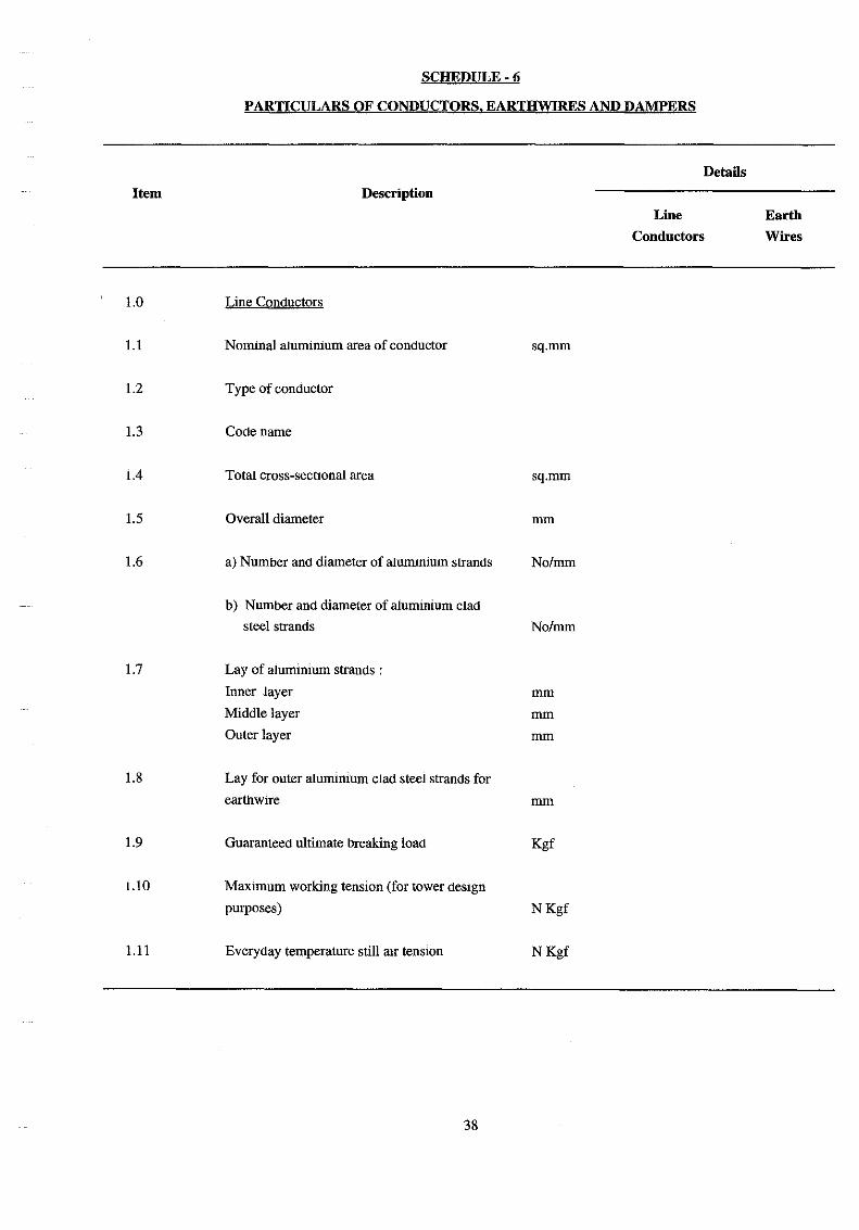
2.0 LINE CONDUCTORS
Line conductors shall be twm 400 sq.mm nommal alurmnium area. All alummlUm alloy conductor "YEW" and
comply with this specification. CharacteristIcs entered in the schedule and with IEC Publication 208.
Each conductor inner layers shall be covered with an approved grease such as Shell ENSIS compound or equal hav
ing a mlmmum drop pomt of 100 Deg. C, which shall completely fill the mnerstics between the strands of the outer
layer. The mass of grease shall represent a mmlmum of 0.7% of the total conductor weight.
There shall be no excess grease remaining on the outside surface whiCh may cause sand the dust particles to adhere
during pulling out and erectIOn of conductor. The outer most layer of the conductors shall be stranded with a nght
hand lay.
AlummlUm alloy conductor shall be made of heat treated alurmmum magnesIum silicon alloy wlfes having me
chanical and electrical properties as per lEC 208.
I
Joints in mdividual wires are permitted in any layer except the outer most, m addition those made m the base rod or
wire before final drawmg, but no two such Jomts shall be too less than 15 meters apart in the complete stranded
conductors. Such JOInts shall be made by resistance built welding and shall be annealed after welding over a dis
tance of atleast 25 cm on each side of the jOints. They should conform to the mechanICal and electncal reqUIrements
for unjointed wires.
The conductors shall be supplied on impregnated drums of approved material so as to enable the conductor to run
smoothly and in lengths convement to handle and erect.
The cut ends of conductors, together with the Jomts, clamps and fittings attached to the conductor themselves shall
be treated in an approved manner to prevent the ingress of arr or moisture.
3.0 EARTH WIRE 1 SHIELD WIRE
The earth wire 1 shield wife shall be a1umimum clad steel conductor consistmg of seven strands. The size of con
ductor shall be 7/3.26mm (58.3 sqmm) a1U1mnium clad steel.
Stranding 7/3.26
Max. resistance at 20 Deg. 0.0101 ohmlkm
The conductor shall be SUItable for climatic condition and electrical system prevailing in Oman as per OES 11.
The direction of lay of the outer layer of strands shall be nght handed. Lay ratio of any layer shall be not greater
than the lay ratio of the layer Immediately beneath It.
The make up of shield wife shall be such that the strand shall remam and shall not twist when the conductor IS cut.
The shield wife shall be manufactured so that no twisting occurs when they are subject to aXial loads; I.e. when un
rolling and stnnging.
All wires used in the manufacti!fe of the shield wires shall be free from protrusion, sharp edges, abraSIOn and any
other Imperfections.
No Jommg of the alummlum clad steel wires shall be permitted.
The creep charactensltcs of the fimshed shall shield be virtually unvarymg so a to mamtam unifonmty.
3.1 INSULATORS
The suspension and tension insulator umts shall comply with lEe 305, 383, 120, 433 and 471 as appropnate.They
shall be of a porcelam long rod aerofoil and open profile type; designed to mimmise build up of dust deposits. Semi
conducting glaze type insulators will not pernutted. Insulators Shall be designed with a view to service 10 a hot
dusty climate with high humidity.
Severe pollulton with high conductivity dust deposits must be expected. This dust combined with a high salt con
tent IS adheSive and wmd protected zones of insulators will be filled with dust depostts.
2
An open profile msulator arrangement IS required with sheds shaped to allow Ihe wmd to blow through givmg a
good self eleamng action under rain, which may only occur for a few days in Ihe year 10 the form of light to medi
um shower.
The string of insulators shall provide minimum creepage of 5940 mm (45mmJKV). The Insulator shall conform to
Ihe ElectrIcal and Mechanical characteristics shown in Schedule-7. The msulator strIng shall be capable of with
standing the required mechanIcal loads within Ihe specified factor of safety. Calculations to be submItted to demon
strate Ihat Ihe mechanICal failing load of the insulator strIng IS sallsfactory base on Ihe factor of safety specified.
The mmimum failing load for msulator strIng shall be 230 KN for suspensIOn and 320 KN for tensIOn.
Double suspensIOn and double tensIOn shall be used at Wadi or road croSSings.
Retaimng pins or locking devices for Ihe insulator umts shall be of phosphor bronze 10 Ihe hard condition. They
shall be so made and shaped such Ihat when installed and under any condition of handling and servIce, Ihey shall
not be displaced. The design shall be such as to allow easy removal for replacmg of insulator umts or fittings with
out the necessity to remove the insulator string from the cross arms.
Retammg pms or locking deVIces shall be incapable of rotation when m position.
All ball and socket Jomts on msulator sets shall be lightly coated with an approved grease before erechon.
4.0 LINE ACCESSORIES
4.1 FITTINGS
Fittings shall comply with BS 3288 Pt. I. SuspensIOn and tensIOn clamps shall be as light as possible and Shall be of
aluminium alloy. All clamps shall be deSIgned to avoid any possibility of deformmg the stranded conductors and
separating the individual strands.
SuspensIOn clamps shall be free to pivot m the vertical plane contaming Ihe conductor and shall permIt Ihe com
plete conductor to slip at a load lower Ihan Ihe breaking load of the conductor. The conductor supporting groove
shall be curved at Its ends m Ihe vertical plane to a radius of l50mm and for a suffiCIent distance to allow for Ihe
conductor leavlOg the clamp at the maximum angle of inclination obtamed in service.
The grooves'in the clampmg piece or pIeces shall be bell moulhed at each end and all conductor grooves and bell
moulh shall be smoolh and free from waves ridges or olher rrregularities.
Particular attention shall be paid to Ihe elimination of corona enusslOn from all parts of suspension clamp. The me
chanical efficiency of tensIOn clamp shall not be affected by melhods of erection mvolving Ihe use of come-along
or SImilar clamp before, dUrIng and after assembly, nor by erection oflhe tensIOn clamp Itself.
Bolts and Nuts shall be m accordance with the appropriate clauses of this specificatIOn. Bolt threads shall be coated
with an approved grease immediately before tightenmg down at erectIOn. Split pms for securing attachment of fit
tings of insulator shall be of stamless steel and shall be backed by washers of approved sIze and gauge.
All insulator strings shall be attached to cross arms by means of Shackles. Hooks shall not be used.
3
4.2 MIDSPAN JOINTS, DEAD ENDS, JUMPER TERMINALS, REPAIR SLEEVES
All midspan joints (tensIOn splices), dead ends (tension clamps) and jumper terminals shall be of the compression
type.
The ends of compressIOn accessories shall be tapered in such a manner that the pressure will be gradually reduced
to zero on that part of the conductor leavmg the accessory and that the conductor stresses caused from bending and
vibration will be reduced to a minimum.
The midspan jomts, dead ends and repaIr sleeves shall not permit slippmg of, or cause damage to, or failure of the
conductor at a load less than 95% of its nOminal ultimate strength.
Jumper terminals for conductor should have a guaranteed slippmg strength not less than 25% of conductor strength.
The conductiVity of all conductor splice fittings m which the conductor IS not continuous shall not be less than that
of an eqmvalent length of conductor.
The design of dead ends shall be such as will facilitate the formation and fittings of jumper loops for the electrical
or mechanical continmty of the conductor or shieldwire. The deSign of all compressIOn fittings (tension clamp and
tension splices and compressIOn type repaIr sleeves) shall be SUCh that only one paIr of dies IS necessary for each
size of conductor.
Where mating surfaces of jumper termmals are to be bolted to the maIn body of the tensIOn clamp, they should be
protected from the manufacturer's works by removable plastic or other means.
Repair sleeve shall be SUItable for repaIring accidental minor damage to conductors and shieldwlres. They shall be
used on conductors where not more than two wlfes of the outer layer are broken and shall only be used for the
shieldwire to repaIr damage to the alummlUm coating of the wires and shall not be used where the steel portion of a
wire is damaged or broken.
Repair sleeves shall consist of two mterlocking parts of a1ummium alloy SUitable for compressing over the conduc
tor. The dies used for compressmg repair sleeves shall be the same size as those used for compressing the alumin
IUm parts of midspan Jomts and dead ends.
Performed alumlmUlD alloy rods may also be used to repaIr conductor. Their performance must be proven by type
testing on the condUctor size muse.
The temperature rise in midspan jOints, compression dead ends, tension clamps, Jumper terminals and similar com
ponents shall not be greater than the temperature nse m the conductor when a current IS passed through properly as
sembled components.
The ferrous parts of midspan jomts and dead ends shall be adequately protected agamst corrOSIOn by the use of a
rust inhibiting compound and a superimposed alumlmUlD sleeve.
4
4.3 VIBRATION DAMPERS
Dampers shall be of the Stockbridge type with clamps made of alummlUm alloy with two or four degrees of reso
nance. They shall be deSigned to mmlmlse vibrations to conductors caused by wmd speeds of 0.5 meters per second
to 10 meters/second for the phase conductors and shieldwlres.
The dampers shall be so deSigned that for the specific conductors and range of span lengths given It should not al
Jaw the bending stram at the conductor clamp to exceed + or - 150 mlcrostrams.
Specific consideration should be given also to spans of either shieldwire or conductor which are to have aircraft
warning spheres or aircraft warning lights erected on them.
The resonant pomts of the damper Impedance characterisllc should be within the vibrallon frequencies set up III the
conductor or shieldwire m questIOn by the range of wind velocities mentIOned and should be proven in the type
tests.
The design shall be such that drooping of the counter-weights does not occur during servIce.
The dampers shall be desIgned to minimise the risk of corona diSCharge or radio interference.
The clampmg device shall be such as to avoid damage to the conductors when Ilghtened, or at any I1me dunng the
servICe life of the dampers. and it shall be free from slippmg.
Dampers shall be so deSigned that dunng operation, the conductor IS not damaged due to the impact of the damper.
The vibratIOn dampers shall be capable of bemg Installed and removed from energIsed lines by means of hot-line
tools, without completely separatlllg components. In addition, the clamp shalI be capable of bemg removed and re
Installed on the conductor at the design torque, without shearing or damagmg bolts. nuts or cup screws.
4.4 SPACERS
Conductor spacers shall be fitted to mamtam 450 mm between the subconductors under normal operating condi
tIOns.
Spacers shall not collapse under short circuit currents.
Spacers shall be so deSIgned as to pennit relative torSional and axial movement between subconductors. This flexi
bility shall be obtallled without the use of metal-to-metal hinged Jomts or sliding parts which could be subject to
wear. Spacer parts consisting of organtc materials are not acceptable.
Spacers shall withstand a compression load to 13 KN applied between conductors and mamtained for 1 minute
without failure. The spacmg between clamps after this load shall be within 5% of the milial spaclllg.
Clamping bolts should be of the captive type of penmt fittmg of the spacers on the subconductors without removal
of the bolts.
The clamping device shall be such as to avoid damage to the conductors when tightened or at any time during the
serVIce life of the spacer and shall be free from slipping.
5
4.5 SPACER DAMPERS
Spacer dampers shall be fitted to mamtam 450mm between subconductors under normal operating conditions and
to protect the subconductors from aeolian vibratIOns.
Spacer dampers shall be so designed as to pennlt relative torsional and axial movement between subconductors.
This flexibility shall he obtained without the use of metal-to-metal hinged Jomts or sliding parts which could be
subject to wear. Spacer parts consIstIng of organic materIals are not acceptable.
Spacer dampers shall not collapse under short CIrcuit current.
Clampmg bolts should be of the captive type to permIt fitting of the spacer dampers on the subconductors without
removal of the bolts.
The clampmg devIce shall be SUCh as to avoid damage to the conductors when lIghtened or at any tIme dunng he
servIce life of the spacer damper and shall be free from slippmg. The spacer dampers should supply the dampmg
ability reqUIred of dampers m Section 4.3 and the spacermg ability of spacers required in SectIon 4.4. The Supplier
should specify the number of spacers required per span to carry out this requirement.
4.6 JUMPER SPACERS
For multiple subCOnductor lines Jumper spacers shall be fitted to mamtam 200 mm between the subconductors.
They shall be of the rigid type deSIgned to maintam a good electrICal connection between subconductors.
Jumper spacers shall be so designed as to penmt relative torsIOnal and axial movement between subconductors
without damage.
The Jumper spacers shall be deSIgned to mcorporate weights of upto SOON to reduce the swmg of the Jumpers.
The spacers and weIght should conform to the galvanIsing and corona requirements of this Specification.
The clampmg deVIce shall be such as to avoid damage to the conductors when tightened or at any time dunng the
servIce life of the Jumper spacer and shall be free from slippmg.
4.7 AIRCRAFT WARNING SPHERES
Day light warmng spheres shall be fitted to shieldwlres of overhead lines m approaches to aIrports or m the normal
'flight paths of low flymg aircraft or where helicopter traffic IS present. These should be as light as possible with a
diameter of not less than 600 mm and made of either plastic fibreglas or alurrumum. They should be smgle coloured
spheres in the colour aviatIOn orapge. They should be bolted or otherwise securely fixed to the shieldwire with non
corroding metal clamps m such a manner that will not damage the shieldwue and will not permit slippmg.
Aircraft warning spheres should conform to the reqUIrements of the CIvil. military aVIatIOn civil defence authorities
of the Sultanate of Oman and the recommendatIons of the ICAO. FAA and CAA.
They should be fitted with drammg holes in the lower half to prevent water accumulatIon m the sphere.
The clamp hardware should be compatible with the shieldwlre material.
6
4.8 AIRCRAFT WARNING LIGHTS
Conductor Marking Lights
Night time warmng lights shall be fitted to phase conductors of overhead lines m approaches to auports or in the
normal flight paths oflow flying aircraft or where helicopter traffic is present.
These should be operated by mduced currents from the phase conductor and should conform to ICAO, FAA and
CAA reqUIrements for light output and VIsibility. The lights should have an average life of 25,000 hours and should
conform to the corona and radio mterference requirements of other line hardwIfe. Any other proven type for this
purpose will be also considered.
The conductor marking lights should conform to the reqUIrements of the civil, military aviation and civil defence
authorities of the Sultanate of Oman.
4.9 ARMOUR RODS
Annour rods shaIl be used for phase conductors and earthwire at every suspenSIOn support. Annour rod shall per
formed type.
4.10 ARCING HORNS
All msulator sets shall be fitted with line end and earth end arc horns. The Arc horns Shall be deSigned that m the
event of flashover no daruage will be suffered by the conductor or conductor fittings or by the msulator itself.
For multiple unit insulator strIng, intennediate arc horns shall be fitted to ensure that the power arc IS kept away
from the porcelam so that exceSSIve thermal stroke of the surface IS avoided.
Gap m between arcing horns shall be as such that to withstand maximum value of impulse flash over voltage.
4.11 LIVE LINE CLEANING ARRANGEMENT
All towers shall be provided with fixed live line cleaning arrangement for msulators. The arrangement shall be com
plete with pIpes, nozzles and couplings for connecting to mobile water tanker. The pIpe line shall be extended to the
nearest location where mobile unit can approach.
5.0 132KV TOWERS AND FOUNDATIONS
5.1 GENERAL
The double CIfCUlt towers shall be suitable for twin bundled conductor 400 sq.mm all a1urmmum alloy (YEW) con
ductor for phase m vertICal formation, with a smgl~ 7/3.26m alulfUmum clad steel earth WIfe giving a maxlfDum
shade angle of 30 Deg. to the top most conductor.
Towers shall be of self supportmg broad based lattice steel constructIOn and shall be provided with 3m, 6m and 9m
extensIOns above standard heIght where reqUIred.
7
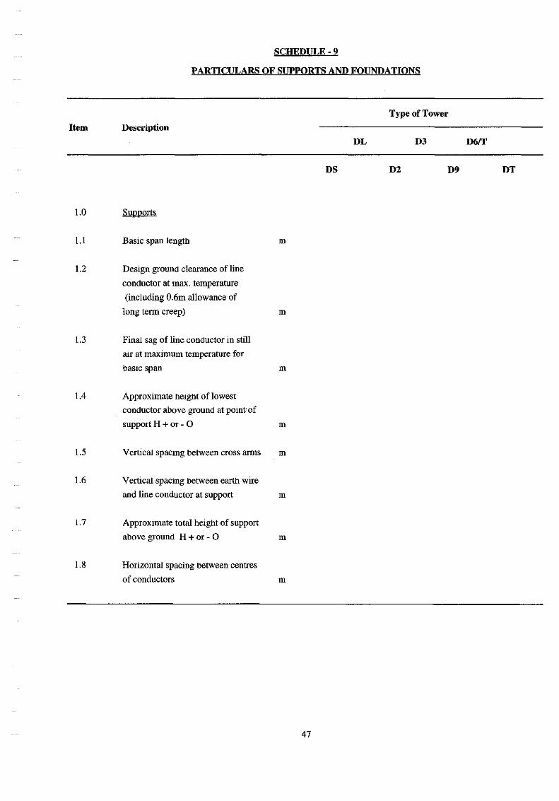
5.2 DESIGN SPANS
The desIgn of all structures shall provide for the followmg basic and weIght spans :
BasIC span
Wind span
All tower - Normal working
Broken wire
Weight Span
N.B.
SuspensIOn towers - Normal working
Broken wire
Tension towers - Normal working ( )
Broken wire {)
335m
410m
310m
670m
505m
1010m
Spans for broken wire condition apply only for the conductor considered broken. Loadings for the mtact conductors
are to be based on Normal Working Spans.
The term basic span length shall mean the honzontal distance between centres of adjacent supports on level ground
from whiCh the heIght of standard supports IS derived with the specified conductor clearances to ground in still rur
at IDaJOIDum temperature.
The It::nll wind span shall mean half the sum of adjacent honzontal span lengths supported on anyone tower.
The term weight span shall mean the equivalent length of the weight of conductor supported at anyone tower at
mmimum temperature m still rur. At suspension positions, the minimum WeIght of conductor supported shall not be
less than 30 percent of the total weight of conductor m the two adjacent spans.
In steeply slopmg country where the gradient between adjacent support pomts exceeds 15 degrees to the honzontal
specIal consideration shall be given to the vertical loading on towers.
8
5.3 TYPES OF SUPPORTS
structures will be designated as follows:
Suspension Tower (0 Deg. - 2 Deg.)
+ 3m Ext.
+6m Ext.
" + 9m Ext.
2-20 Deg. Angel, Section, Heavy SuspensIOn
" "
" "
+ 3m Ext.
+6m Ext.
+ 99m Ext.
20 Deg. - 90 Deg. Angel
"
Terminal
"
"
+ 3m Ext.
+ 6mExt.
+ 3m Ext.
+ 6mExt.
DS
DS+3
DS+6
DS+9
D2
D2+3
D2+6
D2+9
D9
D9+3
D9+6
DT
DT+3
DT+6
SuspensIOn structures shall be equipped with suspensIOn msulators and all other towers with tensIOn msulators.
ExtensIOns are to be fitted without change to the standard height tower.
5.4 CONDUCTOR AND EARTHWIRE SPACING AND CLEARANCE
For all towers. the clearances from conductors, arc horns, Jumper loops and all live metal to the tower steel work
shall not be less than those specified in Schedule 5 under still air conditions and at assumed maxImum swmg of
Jumpers. For D2 type towers 20 Deg. anglelsectionlheavy suspension)these clearance shall also be maintained in
the event that heavy suspension insulators are used instead of tension sets. Where uplift occurs at tension tower po
sitions the mlmmmn clearance between any arcmg horn and the jumper loop of the phase Immediately above It
shall not be less than the ffilmmum still arr clearance from live to earth metal stated in Schedule.
The length of angle tower crossarms shall be such as will ensure that the distances between conductors of the two
circuits at straIght line structure, are maintained in a plane Donna! to the conductors.
For angle towers carrymg deVIation angles upto 60 Deg.C (i.e. types D2 and D9) crossarms shall generally be so
proportiq~ed that live metal clearances are maintamoo under all conditions without the use of jumper suspension m
sulators. Jumper suspensIOn msulators may be used, if required, for angles greater than 60 Deg. (type D9).
Allowance should be made for mcreasing or decreasing the length and varymg the arrangement of all tefffilnal
crossarms to enable downlead span connectIOns to be made m any desired phase sequence.
The maXImum angle of shade protection of the earthwlre to the top conductor shall not be greater than 30 Deg to
vertical at any point in the span.
9
In addition, at every-day temperature with 335m basIC span the still arr direct distance between earthwire and con
ductors at mid-span shall not be less than 6 meters, of which one meter shall be provided by differential sagging.
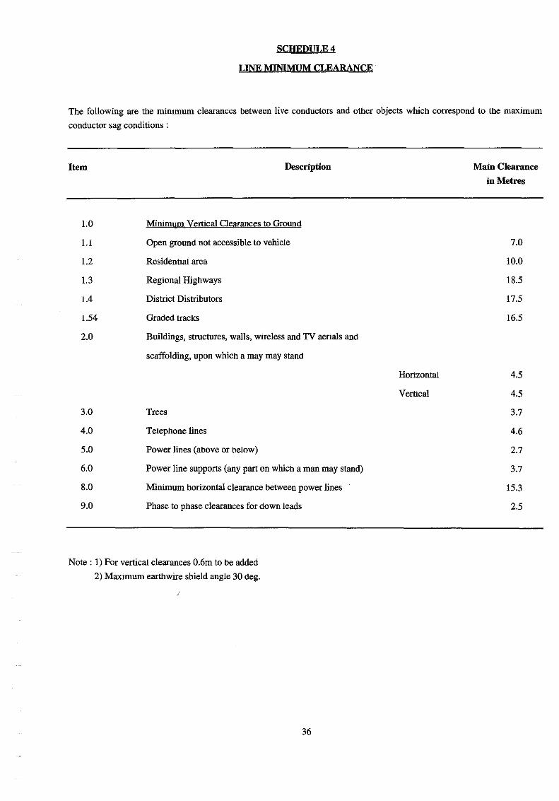
5.5 CLEARANCE TO GROUND AND OTHER FEATURES
The clearance between the line conductors and the ground in still air under the m3XImum specified temperature and
final tensIOn shall not be less than the figure stated in the Schedule of Technical Particulars. An additional clearance
of 0.6m IS reqwred to allow for conductor creep, which shall be Included in the calculation of tower heIghts.
The clearance under all specified conditions between any part of any fences, walls, buildings or other structures on
which a man may stand or against which a ladder may be placed and the nearest line conductor shall be as specified
in SChedule.
5.6 ASSUMED NORMAL WORKING LOADINGS
The assumed maxImum sImultaneous working loadings on towers shall be as follows :
A) Suspension Towers
i) Vertical Loadings - the weIghts of insulators, spacers and all other fittings and the actual dead weight
of specified span lengths of line and earth conductors.
ii) Transverse Loadings - a wind pressure of 971 N/m2 (99 kgflm2) at nght angles to the lines on the
whole project areas of the cOnductors Insulators and earthwlfes.
In addition a wind pressure 15999 N/m2 (163 kgf/m2) on 1112 x the projected area of the members on
one face of the tower. Suspension towers may be used at very small angle deVIation positions where
wind spans and deSIgn considerations permIt.
B) Angel Towers
MaxImum vertical and transverse loadings as described above piUS the transverse and longitudinal components
of the maxImum conductors and earthwire tensions stated in Schedule, resolved for the most critical angles of
deVIation concerned. In addition, angle towers shall be deSIgned for uplift loading eqwvalent to a negatIve
WIght span of 335m.
C) Section. 20 Pea· angle and Heayy Suspension Tower (TYl'es 02)
The loadings for towers type P2 shall be anyone of the following four conditions, whiCh shall in all cases In
clude for transverse loadings as applied to straight line supports :
i) 0-20 Peg. Angle. As for angle tower loadings.
ii) SectIon Loading at nil angel deVIation; weIght span 1340m; unbalanced longitudinal loading at 15%,
maximum working tensIOn for all conductor and earthwlfe POInts.
iii) Uplift Loading. As for condition (ii) but with negatIve weIght span of 670m.
10
IV) Heavy SuspensIOn Tower. fu special positions the tower strength Capacity derived from loadings (i) or
(ii) may be utilised in positions of extra long wind and weight spans, using heavy suspension msulator
sets. The tower shall be so arranged that electncal clearances are maintained either with tension msula
tors or with heavy suspensIOn msulators, in accordance with Clause 5.4. The Tenderer shall mdicate
the maximum wmd span available for towers under this condition. The lowering m conductor attach
ment level when suspensIOn sets are fitted will be taken into account when plottmg profile, and need
not be allowed for m calculating the height to the lowest crossarm.
D) Terminal Towers
Loadings for DT type towers shall be the vertical and transverse loadings as for strrught line supports together
with full maximum longitudinal conductor and eartbwire tensIOns as given In Schedule, together with a plan
angle of entry upto 45 Deg. on the line side. In addition the towers shall be designed for droppers havmg a
maxImum tension of :
a) 1200 Kg. for each sub-conductor, and
b) 500 Kg. for earthwlfes, respectively, actmg at any plane angel of deviation from 0-90 Deg . .to the m
commg line and from the honzontal to the vertical plane.
All terminal towers shall be designed for 2 slack span earthwlfes to substahon structures. Where necessary
auxiliary conductor and earthwire crossarms shall be used for a large angle of deviation mto the Substation and
the bodies of tenrunal towers shall be designed to accommodate such auxiliary crossarms. Terminal towers
Shall also be designed to take slack spans into substation gantry for other substation eqUipment connection.
Auxiliary conductor crossarms and crossarm extensIons shall be deSIgned to carry the down dropper tensions
mentioned above, together with the relevant weights of insulators etc.
E) TenSIOn Tower Erection Loads
The loading conditions for these transmission lines shall be considered and shall provide adequate margins of
strength in the deSigns for unbalanced erectIOn loadings shall be provided. Pomts of support for tower back
stay when strIDging shall be stated.
Factor of safety obtained for 20 Deg. tower under these conditions shall be stated.
5.7 BROKEN WIRE CONDITIONS
SuspensIOn structures shall be deSigned for the reduced verhcal and transverse loadings denved from Clause 5.2
plUS the unbalanced longitudinal force at maximum tensIOn due to the breakage of two SUb-conductors or one eartb
wire.
In the case of a conductor breakage the pull on a suspensIOn tower may be assumed to be reduced to 70% of the
specified maxImum working tension.
Tension structures shall be deSigned for vertical and transverse loadings plUS the full unbalanced longitudinal forces
at maximum working tension due to the simultaneous breakage of 4 adjacent sub-conductors on the same side of
the tower or of one earthwire.
11
Calculation of the stresses in angle tower members under broken wIre loadings shall be made for the worst condi
tions of loading of that particular member for the range of loadings for which the tower may be employed.
For D2 towers, the design shall take account of the possibility that the unbalanced tensIOns referred to Clause 5.6
(C) (ii) and (iii) may act either in the same direction as broken wire forces, or in the opposIte direction, applymg in
creased. torsion moments to the tower body.
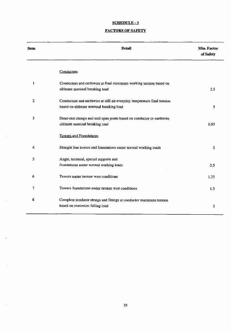
5.8 FACTORS OF SAFETY FOR TOWERS AND FOUNDATIONS
The DS type tower shall be desIgned so that no failure or permanent distortion shall occur when tested with applied
forces eqUIvalent to tWIce the maximum SImultaneous working loadings specified in Clause 5.6.
Each type of angle, termma\, or special tower shall be desIgned so that no failure or permanent distortion shall oc
cur when tested with applied forces equivalent to 2.5 times the maJ(1mum sImultaneous working loadings specified
m Clause 5.6.
Foundations for all towers shall be desIgned to have a factor of safety agaInst overturning or uprooting of not less
than that for the tower. All towers shall also be desIgned so that no failure or permanent distortion occurs when test
ed with applied forces eqUIvalent to 1.25 times the maxlmmn simultaneous working loadings resulting from the as
sumed breakage of conductor(s) specified in clause 5.7.
The factor of safety of foundations shall not be less than 1.5 when the towers are carrying the maximum SImultane
ous working loadings as resulting from the broken wire conditions set out m Clause 5.7.
DesIgn tests on tower types selected by the Engmeer will be requrred to be carned out as specified in Section 7.
5.9 CONSTRUCTION OF SUPPORT STEELWORK
All desIgns shall be such that no trouble shall arise m service from vibration or excessIve deflection due to the use
of too light a section.
Rolled steel sections, flats, plates, bolt and nut bars shal\' unless otherwIse approved, consist of mild steel to 1.S.0.
R630 Grade Fe44A, or such standard as may be approved.
High tensile steel where approved shall be to the reqUIrements of I.S.0. R630 Grade Fe52C or such standard as may
be approved. Steel shall be free from blisters, scale or other defects.
High tensile steel, when stored m the fabncators stockyard pnor to fabncation and galvanismg, shall be marked
continuously throughout ItS length with a light blue water paInt line. In addition the grade nmnber of the steel shall
be painted on and ringed round with paInt.
The standard rolled steel sections used for all mam members including legs, tower top vertIcals, crossarm members
(except bracmg), Shall be not less than 6mm thiCk. No standard rolled steel section IS to be less than 5mm thick.
Bolt holes are not to be more than 1.5mm larger m diameter than ttle corresponding bolt diameter. The design IS to
be such as to keep the number of different parts as small as possible, and is to facilitate transport, erection and
inspectIOn.
12
The ultimate design stress in tensile members shall not exceed the elastic limit strength of the matenal. The ultimate
stress m the compressIOn members shall not exceed a figure obtruned from an approved fonnula to be entered in
Schedule based on the elastic liIDlt strength.
The maxImum allowable slenderness ratIo for various classes of member shall not exceed the values given In
Schedule.
The crossarm tips of tension towers shall be so arranged that two holes for the attachment of conductor erection and
mruntenance tackle are provided adjacent to each hole for tension set shackles. It shall be possible to apply full con
ductor tensIOn safely to either additional attachment pomt.
The nuts of all bolts attaching msulator set droppers, U bolts and earth conductor clamps to the tower shall be
locked with a locking nut.
At locations with steeply sloping ground one or more of the tower legs is to be extended or reduced in lattice steel
framework m convement intervals in an approved manner to give IDlD1mum interference with standard bOdy design.
For use on steeply slopmg ground independent single leg extensIOn shall be deSigned and provided where necessary
for standard and extend towers within the range -2m to +3m m steps of 1m.
The provision of hillside or SpeCial extenslOllS, crossarm steelwork. to standard towers will be made. The calcula
hon of weight of additional steelwork IS to be made on the standard weight per meter of the cross sections em
ployed ungalvanised, measured to centers of frame mtersections plus 7112 percent to allow for all guessting, bolts,
plates, ends, galvanISing etc.
5.10 FOUNDATIONS
The followmg types of concrete block foundations may be employed ..
A) Nonnal Foundation
This type of foundatIOn shall be suitable for soft soil sand or loose gravel occumng generally for the full foun
dation depth.
B) Soft Rock Foundation
This type of foundatIon shall be suitable for when soft rock occurs for more than the bottom 50% of the soft
soil foundation setting depth. The soft rock encountered may be of a homogeneous limestone or coral nature or
of a harder limestone or other rock but bemg fissured and stratified. The soft rock foundatIon shall be SUitable
for both conditions.
C) Hard Rock Foundations
This type of foundatIon shall be suitable for homogeneous hard rock occumng less than 1 meter below ground
level.
13
D) Other Foundarrons
In addition, where ground conditions "exist which do not allow for any of the above deSIgns in an origmaJ or
modified form other types of foundarrons may be employed.
The design of foundatIOns shall follow the SpecificatIOn and assumptIOns set out below and gIven in Schedule.
Such deSIgns are subject to modificalIon to suit Site conditions.
Ultimate foundalIon loadings per leg shall be calculated as follows:
SUSPENSION TOWERS
CompreSSIOn
Uplift
TENSION TOWERS
(Overlirming force + 1/4 applied verlIcalloads + 114 tower weIght)