SUMMARY OF THE NCHRP REPORT 350 CRASH TEST RESULTS FOR THE NARROW CONNECTICUT IMPACT ATTENUATION SYSTEM Prepared by: Erika B. Smith, P.E. May 2003 Report No. 2216—2-02—5 Research Project SPR—2216 Connecticut Department of Transportation Bureau of Engineering and Highway Operations Office of Research and Materials Keith R. Lane, P.E. Director of Research and Materials James M. Sime, P.E. Manager of Research A Project in cooperation with the U.S. Department of Transportation Federal Highway Administration
Transcript
SUMMARY OF THE NCHRP REPORT 350
CRASH TEST RESULTS FOR THE
NARROW CONNECTICUT IMPACT ATTENUATION SYSTEM
Prepared by:
Erika B. Smith, P.E.
May 2003
Report No.
2216—2-02—5
Research Project
SPR—2216
Connecticut Department of Transportation
Bureau of Engineering and Highway Operations
Office of Research and Materials
Keith R. Lane, P.E.
Director of Research and Materials
James M. Sime, P.E.
Manager of Research
A Project in cooperation with the
U.S. Department of Transportation
Federal Highway Administration
ii
Technical Report Documentation Page
Form DOT F 1700.7 (8-72) Reproduction of completed page authorized
1. Report No. FHWA-CT-RD 2216-2-02-5
2. Government Accession No. 3. Recipients Catalog No. 2216-2-02-5
5. Report Date May 2003
4. Title and Subtitle
Summary of the NCHRP Report 350 Crash Test Results for the Narrow Connecticut Impact Attenuation System
6. Performing Organization Code SPR-2216
7. Author(s) Erika B. Smith, P.E.
8. Performing Organization Report No. 2216-2-02-5
10. Work Unit No. (TRIS) 11. Contract or Grant No. CT-HPR Study No. 2216
9. Performing Organization Name and Address Connecticut Department of Transportation Division of Research 280 West Street Rocky Hill, CT 06067-3502
13. Type of Report and Period Covered Final Report October 1997 to August 1999
14. Sponsoring Agency Code SPR-2216
12. Sponsoring Agency Name and Address Connecticut Department of Transportation 2800 Berlin Turnpike Newington, CT 06131-7546
15. Supplementary Notes Prepared in cooperation with the U.S. Department of Transportation, Federal Highway Administration
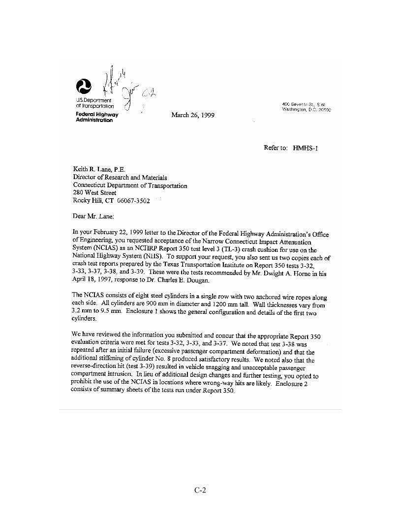
16. Abstract This report on the Narrow Connecticut Impact Attenuation System (NCIAS) is another in a series of test reports that document NCHRP Report 350 compliance of various Connecticut-designed and -developed impact attenuation systems. The report summarizes the results of six full-scale crash tests performed on the NCIAS. All tests were conducted in accordance with the guidelines of NCHRP Report 350 for Test Level 3 devices. NCHRP Report 350 specifies eight tests for redirective, non-gating devices. Three of the eight tests were not conducted on the NCIAS because they are similar to three tests conducted under the NCHRP Report 230 requirements, which the NCIAS passed. The five remaining tests were performed. One test was repeated after one of the cylinders was strengthened. The NCIAS passed all requirements for 4 out of the 5 test designations. It did not pass the requirements for the reverse hit test; therefore, it is required that the installation of the NCIAS not be at locations where it may be struck from the reverse direction. FHWA has approved the use of the NCIAS on the National Highway System at locations where reverse-direction impacts are unlikely. 17. Key Words Impact Attenuation System, Crash Tests, Steel Cylinders, Impact Loading
18. Distribution Statement No restrictions. Hard copy of this document is available through the National Technical Information Service, Springfield, VA 22161. The report is available on-line from the National Transportation Library at http://ntl.bts.gov
19. Security Classif. (Of this report) Unclassified
20. Security Classif.(Of this page) Unclassified
21. No. of Pages 78
20. Price
iii
Disclaimer
The contents of this report reflect the views of the author who
is responsible for the facts and accuracy of the data presented herein.
The contents do not necessarily reflect the official views or policies
of the Connecticut Department of Transportation or the Federal Highway
Administration. The report does not constitute a standard,
specification, or regulation.
iv
Acknowledgments
Special thanks are given to Dr. Charles E. Dougan for his support
of this project throughout the design and implementation stages.
Acknowledgement is made to Dr. John F. Carney, III, for all his work in
the design of this crash system.
Appreciation is also expressed to Mr. Eric C. Lohrey for his
management of the project throughout the design and testing phases.
His organized and systematic method of maintaining records made
completion of this report possible.
Gratefulness is also expressed to the Federal Highway
Administration including Mr. Charles McDevitt for providing assistance
in arranging for the tests and to Connecticut Division Staff, in
particular Mr. Al Alonzi and Ms. Amy Jackson-Grove, for their
commitment to this project.
Thanks are given to Mr. Donald A. Larsen and Ms. Dionysia F.
Oliveira who provided assistance in the completion and review of this
report.
METRIC CONVERSION FACTORS
v
APPROXIMATE CONVERSIONS TO METRIC MEASURES
SYMBOL WHEN YOU KNOW MULTIPLY BY TO FIND SYMBOL
LENGTH in inches 25.4 millimeters mm ft feet 0.305 meters m yd yards 0.914 meters m mi miles 1.61 kilometers km
AREA in2 square inches 645.2 square millimeters mm2 ft2 square feet 0.093 square meters m2 yd2 square yards 0.836 square meters m2 mi2 square miles 2.59 square kilometers km2 ac Acres 0.405 hectares ha
MASS oz ounces 28.35 grams g lb pounds 0.454 kilograms kg T short tons (2000 lb.) 0.907 megagrams Mg (metric ton) (t)
VOLUME fl oz fluid ounces 29.57 milliliters mL gal gallons 3.785 liters L ft3 cubic feet 0.028 cubic meters m3 yd3 cubic yards 0.765 cubic meters m3
TEMPERATURE (exact) ºF Fahrenheit 5/9 (after Celsius ºC temperature subtracting 32) temperature
ILLUMINATION
fc foot-candles 10.76 lux lx fl foot-Lamberts 3.426 candela/m2 cd/m2
FORCE and PRESSURE or STRESS
lbf poundforce 4.45 newtons N lbf/in2 poundforce per 6.89 kilopascals kPa square inch
APPROXIMATE CONVERSIONS FROM METRIC MEASURES
SYMBOL WHEN YOU KNOW MULTIPLY BY TO FIND SYMBOL
LENGTH mm millimeters 0.039 inches in m meters 3.28 feet ft m meters 1.09 yards yd km kilometers 0.621 miles mi
AREA mm2 square millimeters 0.0016 square inches in2 m2 square meters 10.764 square feet ft2 m2 square meters 1.195 square yards yd2 km2 square kilometers 0.386 square miles mi2 ha hectares (10,000 m2) 2.47 acres ac
MASS g grams 0.035 ounces oz kg kilograms 2.202 pounds lb Mg megagrams (1000 kg) 1.103 short tons (2000 lb) T (t) (metric ton)
VOLUME mL milliliters 0.034 fluid ounces fl oz L liters 0.264 gallons gal m3 cubic meters 35.314 cubic feet ft3 m3 cubic meters 1.307 cubic yards yd3
TEMPERATURE (exact) ºC Celsius 9/5 (then Fahrenheit ºF temperature add 32) temperature
ILLUMINATION
Lx lux 0.0929 foot-candles fc cd/m2 candela/m2 0.2919 foot-Lamberts fl
FORCE and PRESSURE or STRESS
N newtons 0.225 poundforce lbf
kPa kilopascals 0.145 poundforce per lbf/in2 square inch
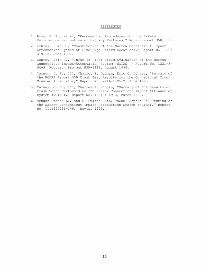
1. Ross, H. E., et al, “Recommended Procedures for the Safety Performance Evaluation of Highway Features,” NCHRP Report 350, 1993.
2. Lohrey, Eric C., “Construction of the Narrow Connecticut Impact-Attenuation System at Five High-Hazard Locations,” Report No. 1221—3—91—2, June 1991.
3. Lohrey, Eric C., “Three (3)-Year Field Evaluation of the Narrow Connecticut Impact-Attenuation System (NCIAS),” Report No. 1221-F-94-3, Research Project HPR-1221, August 1994.
4. Carney, J. F., III, Charles E. Dougan, Eric C. Lohrey, “Summary of the NCHRP Report 350 Crash Test Results for the Connecticut Truck Mounted Attenuator,” Report No. 2216-1-95-2, June 1995.
5. Carney, J. F., III, Charles E. Dougan, “Summary of the Results of Crash Tests Performed on the Narrow Connecticut Impact Attenuation System (NCIAS),” Report No. 1221-1-89-3, March 1989.
6. Menges, Wanda L., and C. Eugene Buth, “NCHRP Report 350 Testing of the Narrow Connecticut Impact Attenuation System (NCIAS),” Report No. TTI:404231-1-6, August 1999.
A-1
APPENDIX A
NCIAS Installation Details
A-2
Figure A-1 Cylinder Fabrication Details
A-3
Figure A-2 Cylinder Fabrication Details continued
A-4
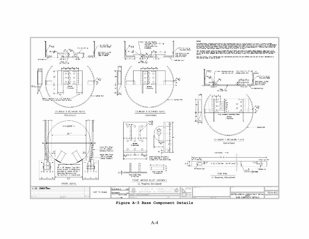
Figure A-3 Base Component Details
A-5
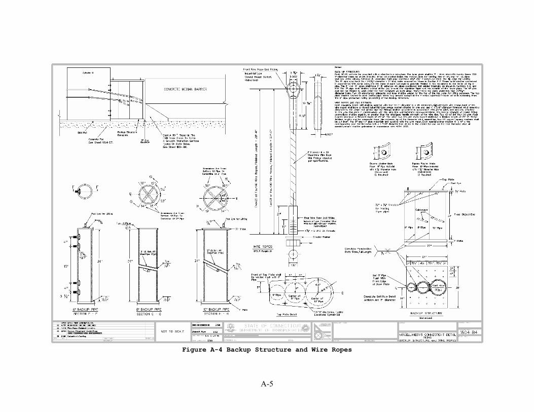
Figure A-4 Backup Structure and Wire Ropes
A-6
Figure A-5 Cover Details
A-7
Figure A-6 Concrete Barrier Curb – End Treatment
A-8
Figure A-7 Concrete Pad Details
A-8
B-1
APPENDIX B
Summary of Test Results and
Typical Photos of NCHRP 350 Tests Performed
B-2
NCHRP 350 Test 3-32
B-3
Figure B1-1 Summary of Results for Test 3-32
B-4
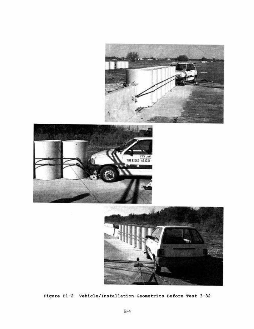
Figure B1-2 Vehicle/Installation Geometrics Before Test 3-32
B-5
Figure B1-3 Sequential Photographs for Test 3-32 (overhead and frontal views)
B-6
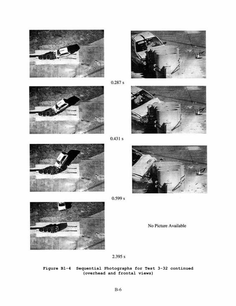
Figure B1-4 Sequential Photographs for Test 3-32 continued (overhead and frontal views)
B-7
Figure B1-5 Installation After Test 3-32
B-8
Figure B1-6 Vehicle After Test 3-32
B-9
NCHRP 350 Test 3-33
B-10
Figure B2-1 Summary of Results for Test 3-33
B-11
Figure B2-2 Vehicle/Installation Geometrics Before Test 3-33
B-12
Figure B2-3 Sequential Photographs for Test 3-33 (overhead and frontal views)
B-13
Figure B2-4 Sequential Photographs for Test 3-33 continued (overhead and frontal views)
B-14
Figure B2-5 Installation After Test 3-33
B-15
Figure B2-6 Vehicle After Test 3-33
B-16
NCHRP 350 Test 3-37
B-17
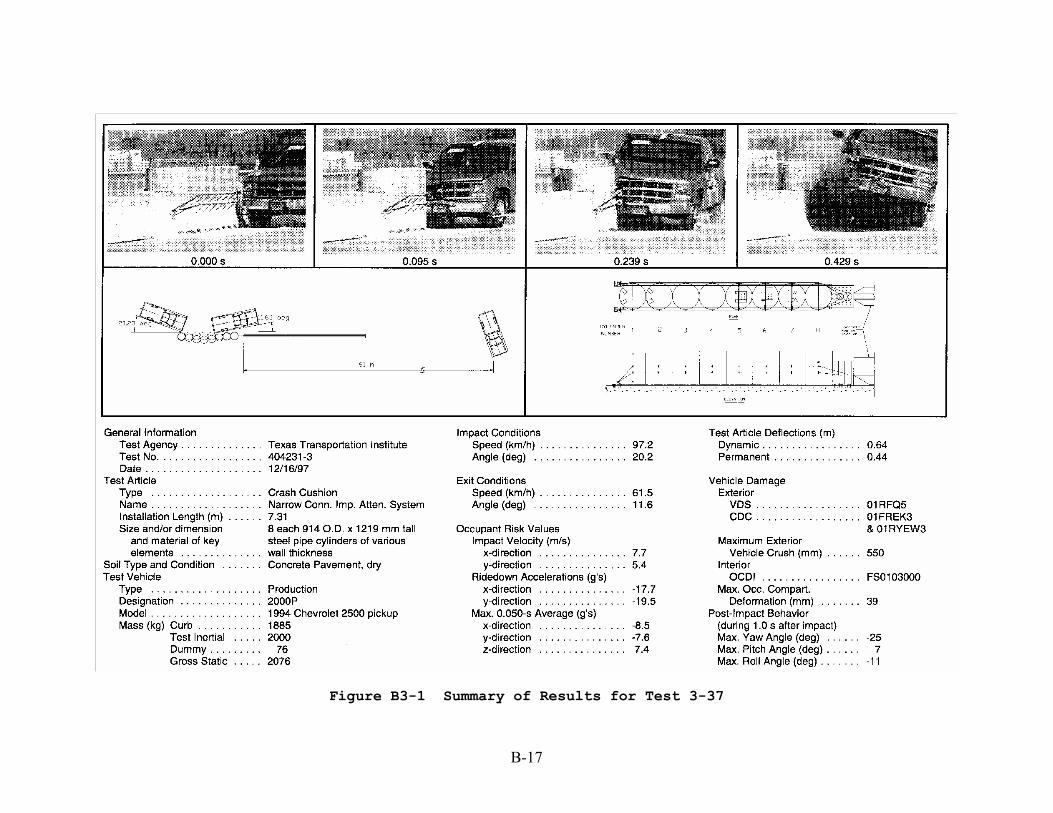
Figure B3-1 Summary of Results for Test 3-37
B-18
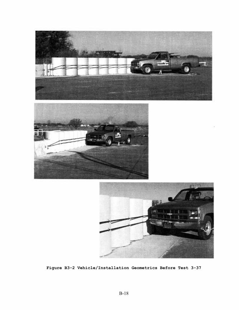
Figure B3-2 Vehicle/Installation Geometrics Before Test 3-37
B-19
Figure B3-3 Sequential Photographs for Test 3-37 (overhead and frontal views)
B-20
Figure B3-4 Sequential Photographs for Test 3-37 continued (overhead and frontal views)
B-21
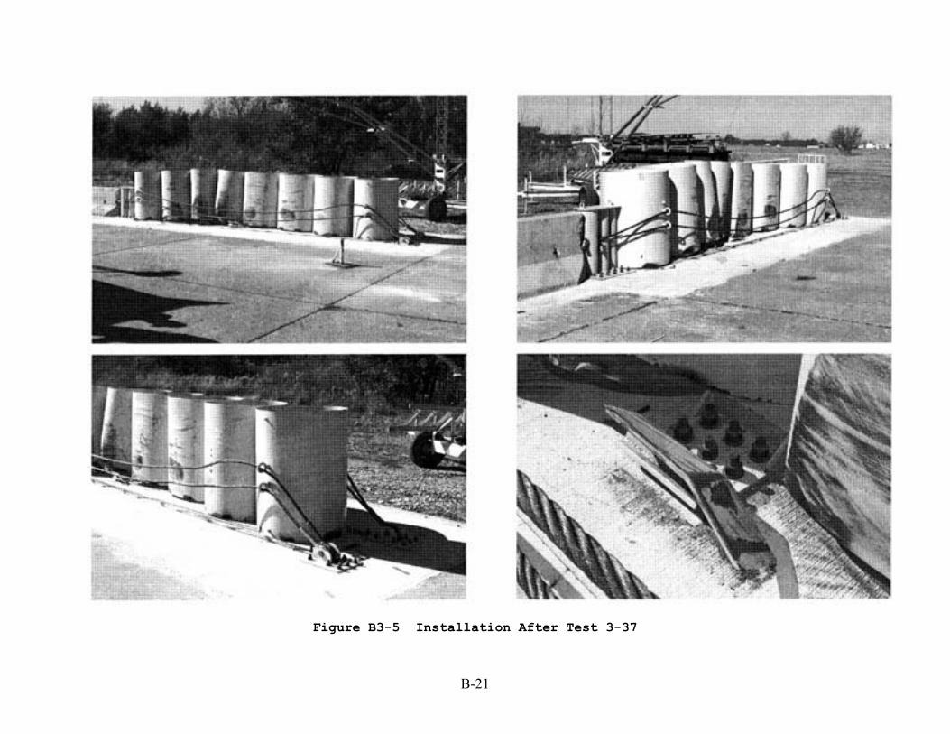
Figure B3-5 Installation After Test 3-37
B-22
Figure B3-6 Vehicle After Test 3-37
B-23
NCHRP 350 Test 3-38(1)
B-24
Figure B4-1 Summary of Results for Test 3-38(1)
B-25
Figure B4-2 Vehicle/Installation Geometrics Before Test 3-38(1)
B-26
Figure B4-3 Sequential Photographs for Test 3-38(1) (overhead and frontal views)
B-27
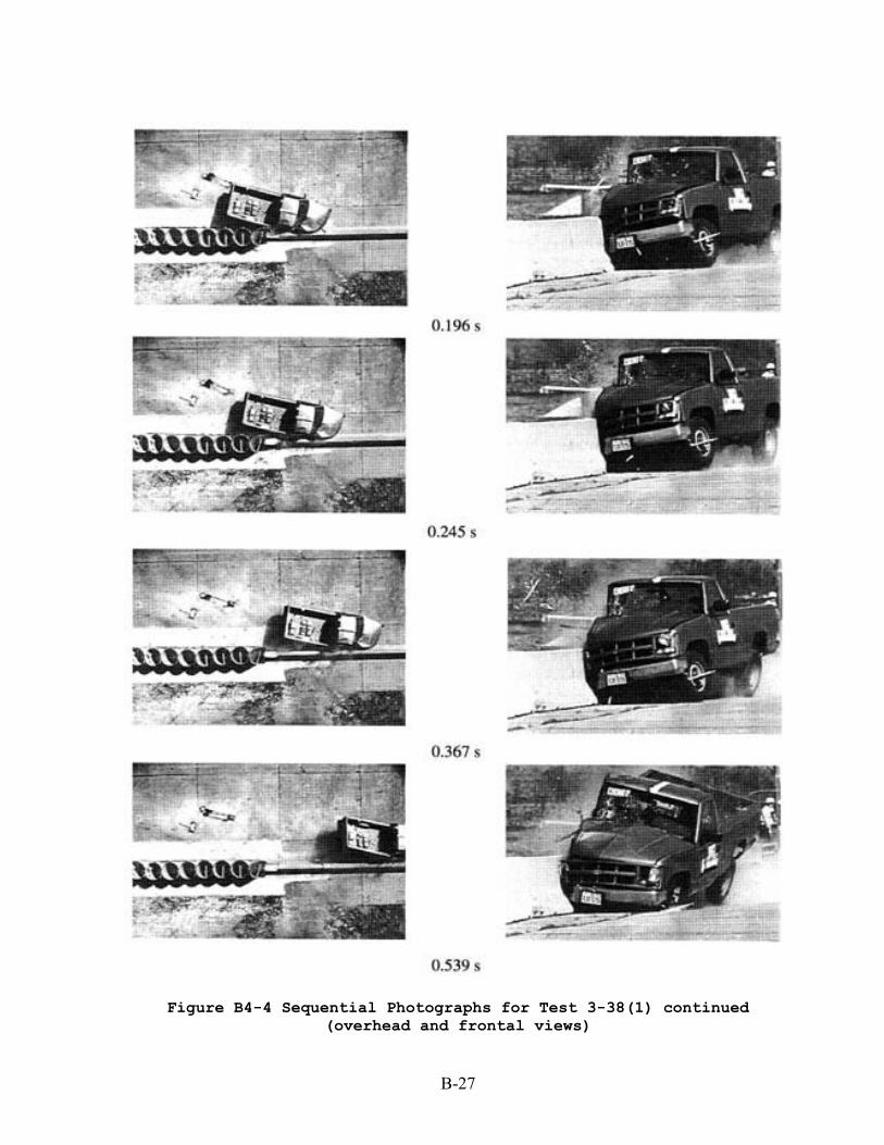
Figure B4-4 Sequential Photographs for Test 3-38(1) continued (overhead and frontal views)
B-28
Figure B4-5 Installation After Test 3-38(1)
B-29
Figure B4-6 Vehicle After Test 3-38(1)
B-30
B-31
NCHRP 350 Test 3-38(2)
B-31
Figure B5-1 Summary of Results for Test 3-38(2)
B-32
Figure B5-2 Vehicle/Installation Geometrics Before Test 3-38(2)
B-33
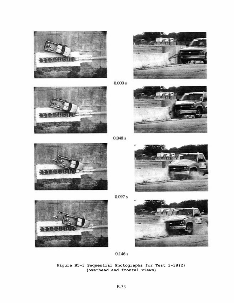
Figure B5-3 Sequential Photographs for Test 3-38(2) (overhead and frontal views)
B-34
Figure B5-4 Sequential Photographs for Test 3-38(2) continued (overhead and frontal views)
B-35
Figure B5-5 Installation After Test 3-38(2)
B-36
Figure B5-6 Vehicle After Test 3-38(2)
B-37
NCHRP 350 Test 3-39
B-38
Figure B6-1 Summary of Results for Test 3-39
B-39
Figure B6-2 Vehicle/Installation Geometrics Before Test 3-39
B-40
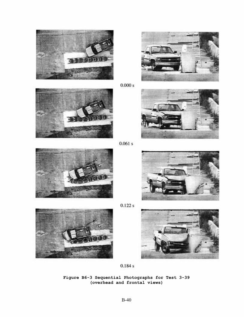
Figure B6-3 Sequential Photographs for Test 3-39 (overhead and frontal views)
B-41
Figure B6-4 Sequential Photographs for Test 3-39 continued (overhead and frontal views)
B-42
Figure B6-5 Installation After Test 3-39
B-43
Figure B6-6 Vehicle After Test 3-39
C-1
APPENDIX C
Federal Highway Approval Letter for Use of the NCIAS on the NHS
at Locations Where Reverse-Direction Impacts are Unlikely