Sun Microsystems, Inc. 901 San Antonio Road Palo Alto, CA 94303 U.S.A. 650-960-1300 Send comments about this document to: [email protected]Sun Fire ™ V100 Server User’s Guide Part No.816-2756-10 Revision A December 2001
Transcript
Sun Microsystems, Inc.901 San Antonio RoadPalo Alto, CA 94303U.S.A. 650-960-1300
Please include the part number of your document in the subject line of your email.
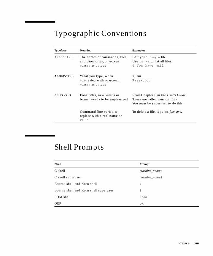
Safety Precautions
For your protection, observe the following safety precautions when setting up your
equipment:
xiv Sun Fire V100 Server User’s Guide • December 2001
■ Follow all cautions and instructions marked on the equipment.
■ Never push objects of any kind through openings in the equipment. Dangerous
voltages may be present. Conductive foreign objects can produce a short circuit
that could cause fire, electric shock, or damage to your equipment.
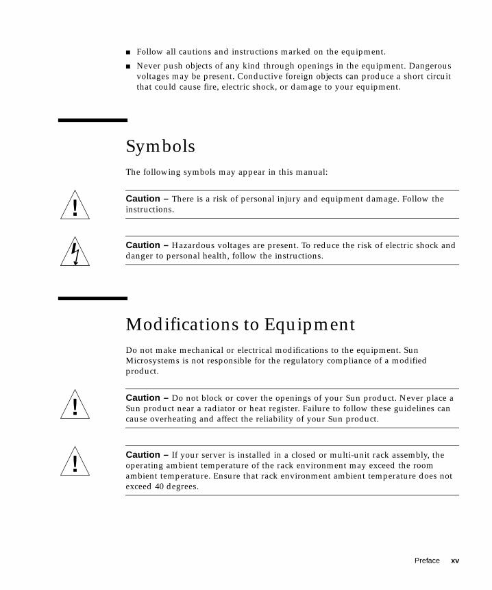
Symbols
The following symbols may appear in this manual:
Caution – There is a risk of personal injury and equipment damage. Follow the
instructions.
Caution – Hazardous voltages are present. To reduce the risk of electric shock and
danger to personal health, follow the instructions.
Modifications to Equipment
Do not make mechanical or electrical modifications to the equipment. Sun
Microsystems is not responsible for the regulatory compliance of a modified
product.
Caution – Do not block or cover the openings of your Sun product. Never place a
Sun product near a radiator or heat register. Failure to follow these guidelines can
cause overheating and affect the reliability of your Sun product.
Caution – If your server is installed in a closed or multi-unit rack assembly, the
operating ambient temperature of the rack environment may exceed the room
ambient temperature. Ensure that rack environment ambient temperature does not
exceed 40 degrees.
Preface xv
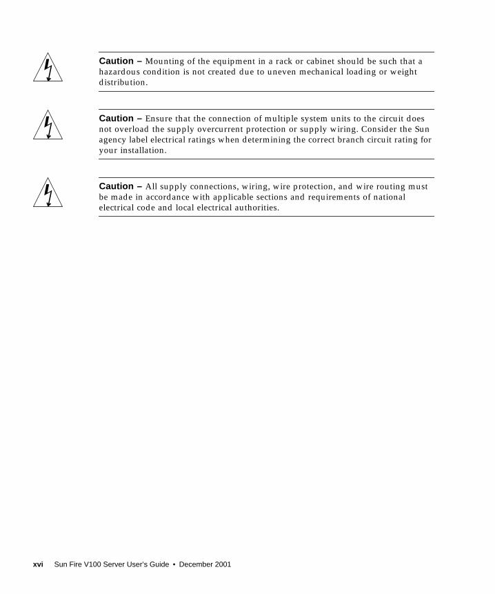
Caution – Mounting of the equipment in a rack or cabinet should be such that a
hazardous condition is not created due to uneven mechanical loading or weight
distribution.
Caution – Ensure that the connection of multiple system units to the circuit does
not overload the supply overcurrent protection or supply wiring. Consider the Sun
agency label electrical ratings when determining the correct branch circuit rating for
your installation.
Caution – All supply connections, wiring, wire protection, and wire routing must
be made in accordance with applicable sections and requirements of national
electrical code and local electrical authorities.
xvi Sun Fire V100 Server User’s Guide • December 2001
PART I Installation and Configuration
CHAPTER 1
Introducing the Sun Fire V100Server
This chapter gives an overview of the Sun Fire V100 server. It lists the features of the
server and the contents of the ship kit, and lists the optional components available.
It also gives you an overview of the installation process.
The chapter contains the following sections:
■ “Contents of the Ship Kit” on page 3
■ “Preinstalled Software” on page 3
■ “Optional Components” on page 4
■ “Installation Quick Start” on page 5
1
Overview of the Sun Fire V100 Server
The Sun Fire V100 server is a single-processor server in a one rack unit (1 RU)
chassis. It is designed to maximize the density of high-performance Solaris servers in
a rack.
FIGURE 1-1 The Sun Fire V100 server
The server is ideal for:
■ Internet service providers
■ Telecommunications carriers
■ Financial services
■ Corporate customer networks
■ Anyone who wants to maximize the density of Solaris servers in a rack
The Sun Fire V100 server has the following features:
■ A removable system configuration card containing the server’s host ID, MAC
address, and NVRAM settings
■ Rackmounting enclosure with single power supply
■ Four DIMM sockets
■ Two 10/100 Mbps RJ-45 Ethernet ports
■ Console/Lights Out Management RJ-45 serial port
■ Second RJ-45 serial port
■ Two USB ports
■ Support for up to two low-profile, 3.5-inch IDE disks
■ Solaris operating environment (64 bit) preinstalled
■ Slimline CD-ROM drive
2 Sun Fire V100 Server User’s Guide • December 2001
Contents of the Ship Kit
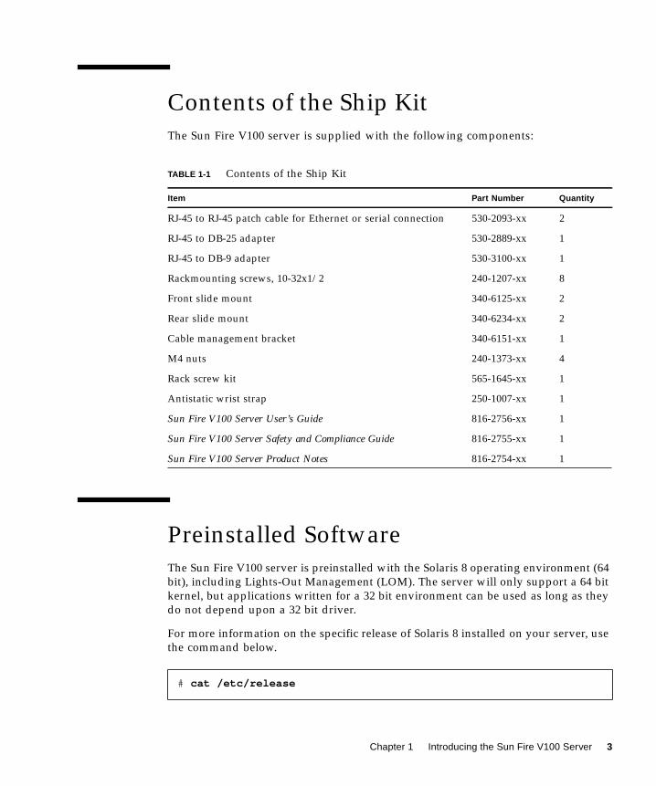
The Sun Fire V100 server is supplied with the following components:
Preinstalled Software
The Sun Fire V100 server is preinstalled with the Solaris 8 operating environment (64
bit), including Lights-Out Management (LOM). The server will only support a 64 bit
kernel, but applications written for a 32 bit environment can be used as long as they
do not depend upon a 32 bit driver.
For more information on the specific release of Solaris 8 installed on your server, use
the command below.
TABLE 1-1 Contents of the Ship Kit
Item Part Number Quantity
RJ-45 to RJ-45 patch cable for Ethernet or serial connection 530-2093-xx 2
RJ-45 to DB-25 adapter 530-2889-xx 1
RJ-45 to DB-9 adapter 530-3100-xx 1
Rackmounting screws, 10-32x1/2 240-1207-xx 8
Front slide mount 340-6125-xx 2
Rear slide mount 340-6234-xx 2
Cable management bracket 340-6151-xx 1
M4 nuts 240-1373-xx 4
Rack screw kit 565-1645-xx 1
Antistatic wrist strap 250-1007-xx 1
Sun Fire V100 Server User’s Guide 816-2756-xx 1
Sun Fire V100 Server Safety and Compliance Guide 816-2755-xx 1
Sun Fire V100 Server Product Notes 816-2754-xx 1
# cat /etc/release
Chapter 1 Introducing the Sun Fire V100 Server 3
Optional Components
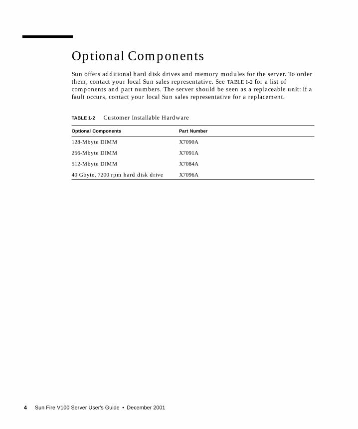
Sun offers additional hard disk drives and memory modules for the server. To order
them, contact your local Sun sales representative. See TABLE 1-2 for a list of
components and part numbers. The server should be seen as a replaceable unit: if a
fault occurs, contact your local Sun sales representative for a replacement.
TABLE 1-2 Customer Installable Hardware
Optional Components Part Number
128-Mbyte DIMM X7090A
256-Mbyte DIMM X7091A
512-Mbyte DIMM X7084A
40 Gbyte, 7200 rpm hard disk drive X7096A
4 Sun Fire V100 Server User’s Guide • December 2001
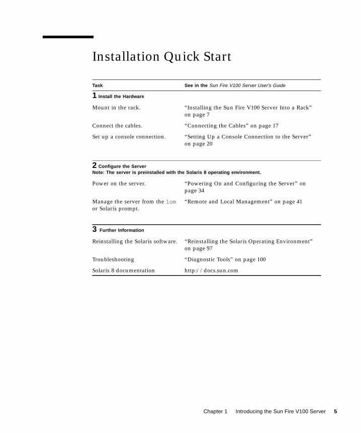
Installation Quick Start
Task See in the Sun Fire V100 Server User’s Guide
1 Install the Hardware
Mount in the rack. “Installing the Sun Fire V100 Server Into a Rack”
on page 7
Connect the cables. “Connecting the Cables” on page 17
Set up a console connection. “Setting Up a Console Connection to the Server”
on page 20
2 Configure the ServerNote: The server is preinstalled with the Solaris 8 operating environment.
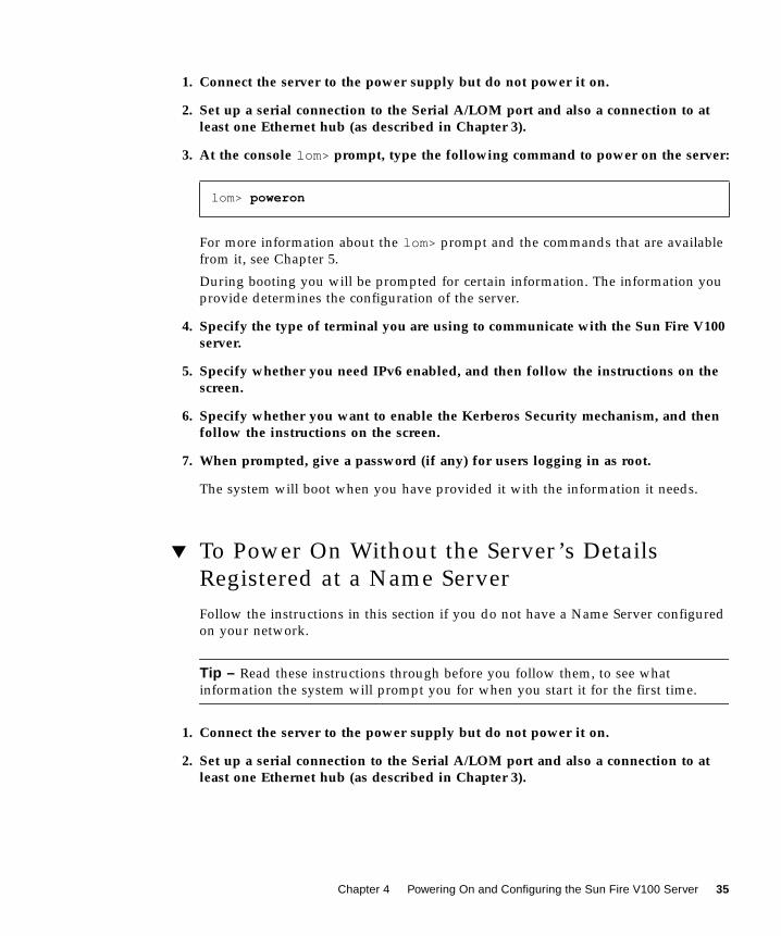
Power on the server. “Powering On and Configuring the Server” on
page 34
Manage the server from the lomor Solaris prompt.
“Remote and Local Management” on page 41
3 Further Information
Reinstalling the Solaris software. “Reinstalling the Solaris Operating Environment”
on page 97
Troubleshooting “Diagnostic Tools” on page 100
Solaris 8 documentation http://docs.sun.com
Chapter 1 Introducing the Sun Fire V100 Server 5
6 Sun Fire V100 Server User’s Guide • December 2001
CHAPTER 2
Installing the Sun Fire V100 ServerInto a Rack
This chapter explains how to install the Sun Fire V100 server into a rack and
describes the mounting options available. It also contains a guide on connecting the
cables to the server. The information is provided in the following sections:
■ “Choosing Between a Rack and a Cabinet” on page 8
■ “Installing the Sun Fire V100 Server Into a 19-Inch Wide or 72-inch Tall Four-Post
Rack” on page 8
■ “Connecting the Cables” on page 17
7
Choosing Between a Rack and a Cabinet
The Sun Fire V100 server can be installed in either a rack or a cabinet. Factors that
might influence your decision include:
■ SecurityIf other people have access to the room in which your servers are located, you can
increase security by locking the servers in a cabinet.
■ Thermal issuesCabinets often require additional fans, because the systems installed in them
generate heat in an enclosed space. Two-post racks, however, may require no
special cooling systems.
■ FlooringTwo-post telco relay racks are designed so that cables can be run overhead.
Cabinets often require cables to be run under the floor.
Installing the Sun Fire V100 Server Into a19-Inch Wide or 72-inch Tall Four-PostRack
The 19-Inch Rackmounting Kit
The mounting slides can each be used on either side of the rack. The parts required
are listed in TABLE 2-1. The part number of the rackmounting kit is X6919A.
TABLE 2-1 19-inch Rackmounting Kit
Item Quantity Part No.
Front slide 2 340-6125
Rear slide 2 340-6234
Cable management bracket 1 340-6151
M4 nuts 4 240-1373
Rack screw kit 1 565-1645
8 Sun Fire V100 Server User’s Guide • December 2001
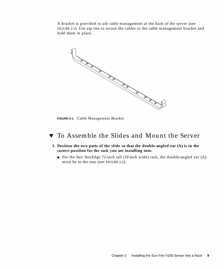
A bracket is provided to aid cable management at the back of the server (see
FIGURE 2-1). Use zip ties to secure the cables to the cable management bracket and
hold them in place.
FIGURE 2-1 Cable Management Bracket
▼ To Assemble the Slides and Mount the Server
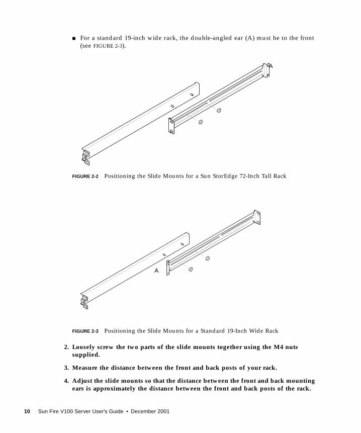
1. Position the two parts of the slide so that the double-angled ear (A) is in thecorrect position for the rack you are installing into.
■ For the Sun StorEdge 72-inch tall (19-inch wide) rack, the double-angled ear (A)
must be to the rear (see FIGURE 2-2).
Chapter 2 Installing the Sun Fire V100 Server Into a Rack 9
■ For a standard 19-inch wide rack, the double-angled ear (A) must be to the front
(see FIGURE 2-3).
FIGURE 2-2 Positioning the Slide Mounts for a Sun StorEdge 72-Inch Tall Rack
FIGURE 2-3 Positioning the Slide Mounts for a Standard 19-Inch Wide Rack
2. Loosely screw the two parts of the slide mounts together using the M4 nutssupplied.
3. Measure the distance between the front and back posts of your rack.
4. Adjust the slide mounts so that the distance between the front and back mountingears is approximately the distance between the front and back posts of the rack.
A
A
10 Sun Fire V100 Server User’s Guide • December 2001
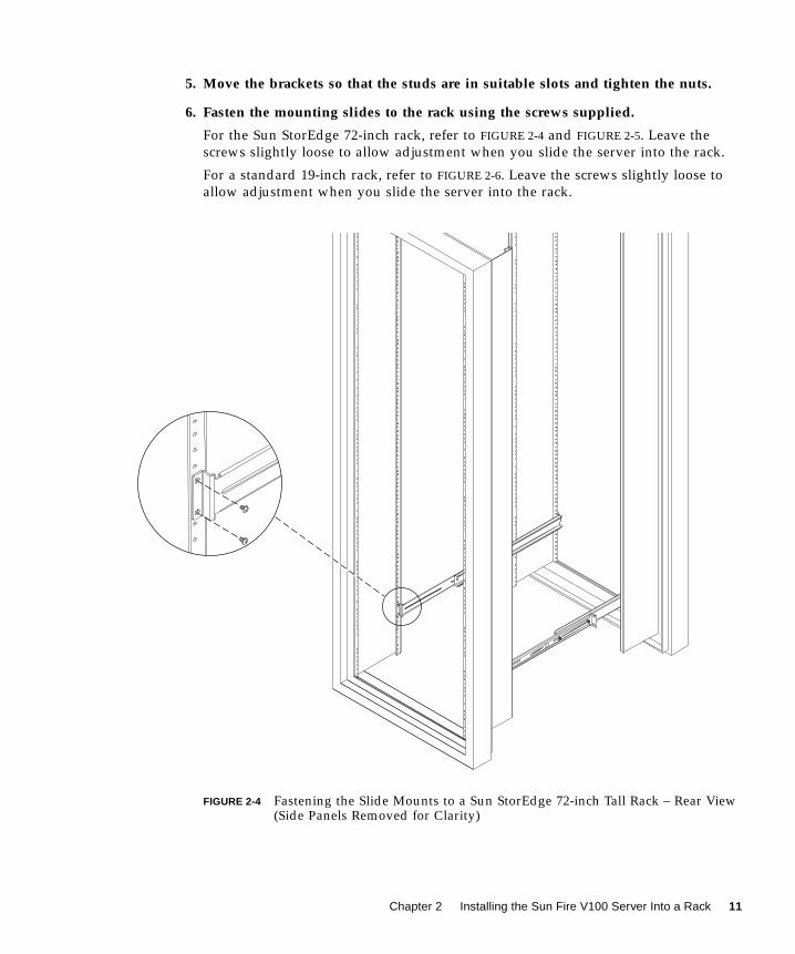
5. Move the brackets so that the studs are in suitable slots and tighten the nuts.
6. Fasten the mounting slides to the rack using the screws supplied.
For the Sun StorEdge 72-inch rack, refer to FIGURE 2-4 and FIGURE 2-5. Leave the
screws slightly loose to allow adjustment when you slide the server into the rack.
For a standard 19-inch rack, refer to FIGURE 2-6. Leave the screws slightly loose to
allow adjustment when you slide the server into the rack.
FIGURE 2-4 Fastening the Slide Mounts to a Sun StorEdge 72-inch Tall Rack – Rear View(Side Panels Removed for Clarity)
Chapter 2 Installing the Sun Fire V100 Server Into a Rack 11
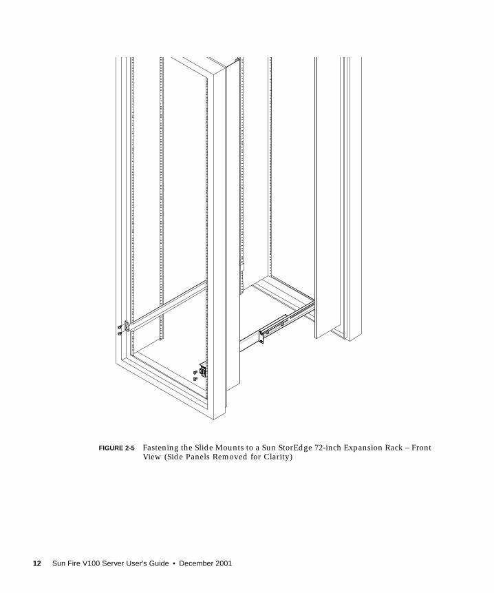
FIGURE 2-5 Fastening the Slide Mounts to a Sun StorEdge 72-inch Expansion Rack – FrontView (Side Panels Removed for Clarity)
12 Sun Fire V100 Server User’s Guide • December 2001
FIGURE 2-6 Fastening the Slide Mounts to a Standard 19-inch Rack
7. Slide the server into the rack (see FIGURE 2-7).
Chapter 2 Installing the Sun Fire V100 Server Into a Rack 13
FIGURE 2-7 Sliding the Sun Fire V100 Server Into a Standard 19-Inch Rack
14 Sun Fire V100 Server User’s Guide • December 2001
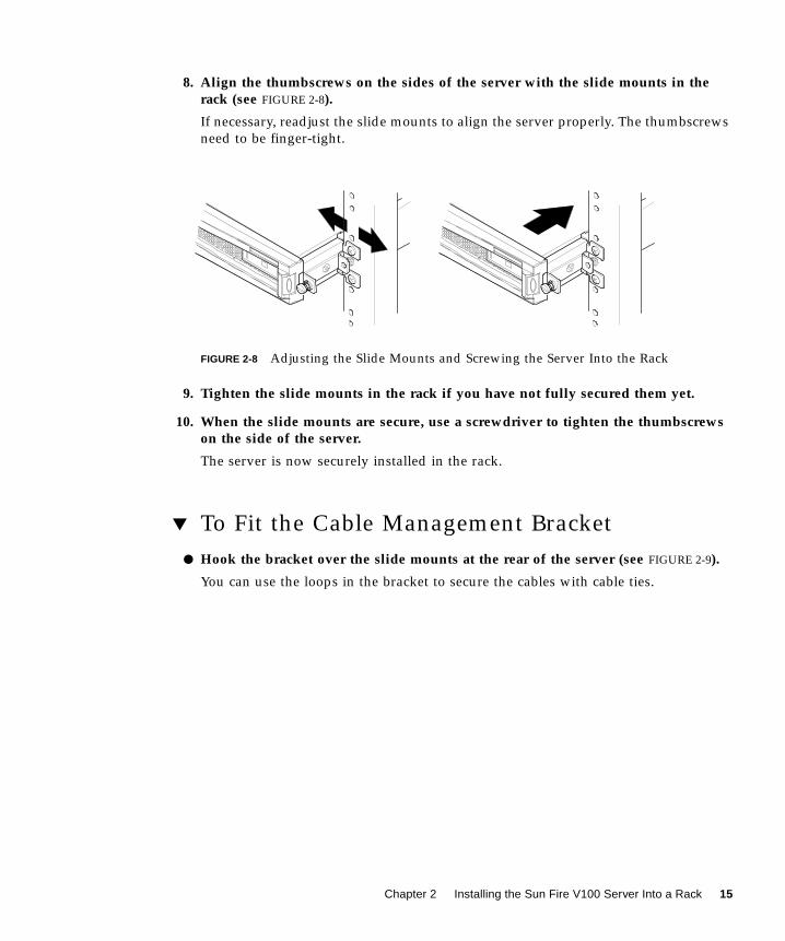
8. Align the thumbscrews on the sides of the server with the slide mounts in therack (see FIGURE 2-8).
If necessary, readjust the slide mounts to align the server properly. The thumbscrews
need to be finger-tight.
FIGURE 2-8 Adjusting the Slide Mounts and Screwing the Server Into the Rack
9. Tighten the slide mounts in the rack if you have not fully secured them yet.
10. When the slide mounts are secure, use a screwdriver to tighten the thumbscrewson the side of the server.
The server is now securely installed in the rack.
▼ To Fit the Cable Management Bracket
● Hook the bracket over the slide mounts at the rear of the server (see FIGURE 2-9).
You can use the loops in the bracket to secure the cables with cable ties.
Chapter 2 Installing the Sun Fire V100 Server Into a Rack 15
FIGURE 2-9 Fitting the Cable Management Bracket to a Sun StorEdge or a Standard 19-Inch Rack
Tips for Using a Sun StorEdge 72-inch Rack■ For maximum stability, fill the rack from the bottom up and at the top leave at
least four rack units empty.
■ To prevent warm air flowing to the front of the rack and being recirculated (which
would reduce the efficiency of your cooling system and potentially cause
overheating), close off the empty spaces at the top of the rack with filler panels.
The following filler panels are available from your local Sun sales representative:
Cable management bracket
16 Sun Fire V100 Server User’s Guide • December 2001
■ 1 RU (part number: 330-2610-01)
■ 2 RU (part number: 330-2611-01)
■ 3 RU (part number: 330-2613-01)
■ 4 RU (part number: 330-2614-01)
■ 5 RU (part number: 330-2615-01)
■ Position your racks so that the warm air exhaust from one rack does not flow
directly into the cool air intake area for another.
■ If space is limited at the back of your Sun StorEdge 72-inch rack, install a
redundant fan tray (part number: X9819A) into the top of the rack. This pulls air
up through the top of the rack to prevent the build-up of heat behind it.
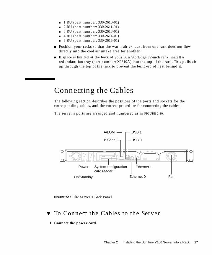
Connecting the Cables
The following section describes the positions of the ports and sockets for the
corresponding cables, and the correct procedure for connecting the cables.
The server’s ports are arranged and numbered as in FIGURE 2-10.
FIGURE 2-10 The Server’s Back Panel
▼ To Connect the Cables to the Server
1. Connect the power cord.
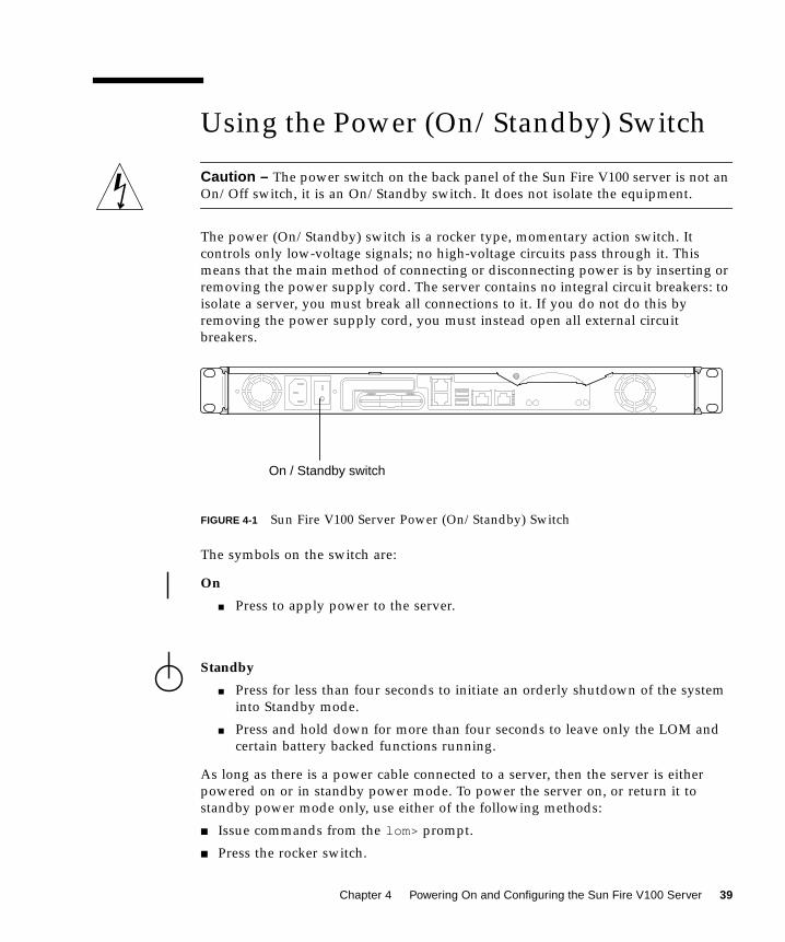
On/Standby
System configurationcard reader
B Serial
Ethernet 1
USB 0
Power
A/LOM USB 1
FanEthernet 0
Chapter 2 Installing the Sun Fire V100 Server Into a Rack 17
2. Connect a serial device.
For more information, see “Setting Up a Console Connection to the Server” on
page 20.
If you want to use the server’s Lights Out Management (LOM) facilities, use the port
labeled Serial A/LOM to make your serial connection to the server.
Note – The Sun Fire V100 server is supplied with shielded serial cables. Use only
these cables when making serial connections to the server.
3. Connect the server to a maximum of two Ethernet hubs.
You need connect to an Ethernet hub only if you intend to use the server in a
network.
4. Connect the server to a maximum of two USB devices.
If required.
5. If you intend to configure the server directly from a dumb terminal or a Sunworkstation, connect the serial cable into the DB-25 serial adapter that wassupplied with the server, and connect the adapter to the serial connector on theterminal or on the Sun workstation.
Refer to Chapter 4 for information about powering on the system.
Note – The DB-25 serial adapter may not work with all terminals. If you have
problems, refer to your terminal manual to check its compatibility with the Sun
adapter.
Caution – AC-powered Sun products are designed to work with single-phase
power systems that have a grounded neutral conductor. To reduce the risk of electric
shock, do not connect Sun products to any other type of power system. Contact your
facilities manager or a qualified electrician if you are not sure what type of power is
supplied to your building.
Caution – Your AC-powered Sun product is packaged with a grounding type
(three-wire) power cord. To reduce the risk of electric shock, always connect the cord
to a grounded outlet.
18 Sun Fire V100 Server User’s Guide • December 2001
CHAPTER 3
Communicating With the Server
This chapter provides information on setting up a console connection to a Sun Fire
V100 server using a variety of devices. The information is contained in the following
sections:
■ “Setting Up a Console Connection to the Server” on page 20
■ “Connecting to the Server Using a Sun Workstation or ASCII Terminal” on
page 23
■ “Connecting to the Server Using a Terminal Server” on page 25
■ “Connecting to the Server Using a System Running Microsoft Windows” on
page 27
■ “Connecting to the Server Using a Handheld Device” on page 29
19
Setting Up a Console Connection to theServer
To perform the initial configuration and to continue to monitor and manage a server,
you can connect any of the following devices to the appropriate serial port on the
server’s back panel:
■ Sun workstation or ASCII terminal connected directly to the server
■ Sun workstation connected via a terminal server
■ Modem
■ PC
■ Handheld device
Which Is the Appropriate Serial Port?
There are two serial ports on the rear of the Sun Fire V100 server. TABLE 3-1 lists the
serial port labels and function of each port.
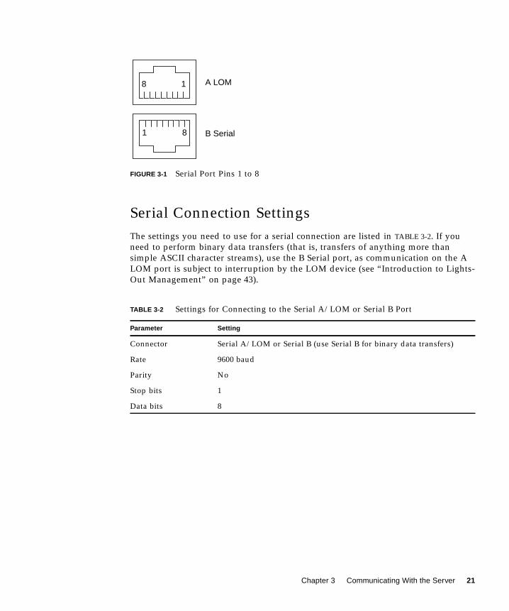
Serial Port Pin Arrangement
When viewed from the back of the server, the pin arrangement of the RJ-45 ports is
as shown in FIGURE 3-1.
TABLE 3-1 Server Serial Ports
Serial Port Purpose Description
A LOM Issue LOM
commands
This port is dedicated to the Lights Out
Management (LOM) device in the server.
B Serial • Perform binary
data transfers
• Set up a modem
connection
Communication on the A/LOM port is subject to
interruption by the LOM device, therefore the A/
LOM port does not assert the constant DTR signal
required by a modem.
20 Sun Fire V100 User’s Guide • December 2001
FIGURE 3-1 Serial Port Pins 1 to 8
Serial Connection Settings
The settings you need to use for a serial connection are listed in TABLE 3-2. If you
need to perform binary data transfers (that is, transfers of anything more than
simple ASCII character streams), use the B Serial port, as communication on the A
LOM port is subject to interruption by the LOM device (see “Introduction to Lights-
Out Management” on page 43).
TABLE 3-2 Settings for Connecting to the Serial A/LOM or Serial B Port
Parameter Setting
Connector Serial A/LOM or Serial B (use Serial B for binary data transfers)
Rate 9600 baud
Parity No
Stop bits 1
Data bits 8
18
1 8
A LOM
B Serial
Chapter 3 Communicating With the Server 21
Serial Adapters
Depending on the type of device you use to connect to the server, you could need to
use either a DB-25 or DB-9 serial adapter. TABLE 3-3 describes which type to use, and
the following sections describe the crossovers each adapter performs.
The Sun DB-25 Adapter
To connect to a Solaris tip session or to a VT100 terminal, you need to use either the
DB-25 (25-Pin DSUB Male to 8-POS RJ-45 Female) adapter that is supplied by Sun
(part no. 530-2889) with your system, or an alternative adapter that performs the
same pin crossovers. The Sun-supplied DB-25 adapter enables you to connect to any
Sun system. The crossovers it performs are listed in TABLE 3-4.
TABLE 3-3 Serial Adapters
Terminal Device Adapter
Sun workstation, ASCII terminal, or
terminal server
DB-25
PC or laptop DB-9 (female, supplied by Sun)
Handheld device DB-9 (male, not supplied by Sun)
TABLE 3-4 Pin Crossovers in the Sun DB-25 (25-Pin) Adapter
Serial Port (RJ-45 Connector) Pin 25-Pin Connecter
Pin 1 (RTS) Pin 5 (CTS)
Pin 2 (DTR) Pin 6 (DSR)
Pin 3 (TXD) Pin 3 (RXD)
Pin 4 (Signal Ground) Pin 7 (Signal Ground)
Pin 5 (Signal Ground) Pin 7 (Signal Ground)
Pin 6 (RXD) Pin 2 (TXD)
Pin 7 (DSR) Pin 20 (DTR)
Pin 8 (CTS) Pin 4 (RTS)
22 Sun Fire V100 User’s Guide • December 2001
▼ To Use the DB-25 Adapter
1. Insert one end of the standard RJ-45 patch cable supplied with the Sun Fire V100server into one of the server’s serial ports.
2. Insert the other end of the RJ-45 patch cable into the supplied DB-25 adapter.
3. Attach the adapter to the appropriate port in your serial device.
The Sun DB-9 Adapter
Some devices, such as a PC or handheld computer, require you to use either a male
or female DB-9 adapter. The Sun DB-9 adaptor (part number 530-3100-xx) is a 9-Pin
DSUB female to 8-POS RJ-45 female adapter. To connect to any device that has a 9-
pin serial connector, use a DB-9 (9-pin) adapter that performs the pin crossovers
listed in TABLE 3-5.
Connecting to the Server Using a SunWorkstation or ASCII Terminal
To connect to the server using either a Sun workstation or an ASCII terminal, you
need:
■ DB-25 adapter
TABLE 3-5 Pin Crossovers in the DB-9 (9-Pin) Adapter
Serial Port (RJ-45 Connector) Pin 9-Pin Connector
Pin 1 (RTS) Pin 8 (CTS)
Pin 2 (DTR) Pin 6 (DSR)
Pin 3 (TXD) Pin 2 (RXD)
Pin 4 (Signal Ground) Pin 5 (Signal Ground)
Pin 5 (Signal Ground) Pin 5 (Signal Ground)
Pin 6 (RXD) Pin 3 (TXD)
Pin 7 (DSR) Pin 4 (DTR)
Pin 8 (CTS) Pin 7 (RTS)
Chapter 3 Communicating With the Server 23
■ RJ-45 to RJ-45 patch cable
Both are supplied with the Sun Fire V100 server.
▼ To Connect to the Server Using a Sun
Workstation
1. Connect to the server using the RJ-45 patch cable and DB-25 adapter as describedin “To Use the DB-25 Adapter” on page 23.
2. From a terminal session, type:
The tip command above is for a console that is using its ttya serial port. If you later
configure your console to use ttyb, type the following to set up a tip session:
For information about dedicating the console to Serial B, see “Managing the Sun Fire
V100 Server From the lom> Prompt” on page 43.
For information about how to power on and configure the server, go to “Powering
On and Configuring the Server” on page 34.
▼ To Connect to the Server Using an ASCII
Terminal
1. Set up a connection between the terminal and the Sun Fire V100 server.
See “To Use the DB-25 Adapter” on page 23.
2. For the General terminal settings, refer to the terminal operating manual.
# tip /dev/term/a -9600
# tip /dev/term/b -9600
24 Sun Fire V100 User’s Guide • December 2001
3. Make the setting changes shown below.
The lom> prompt appears.
For information about how to power on and configure the server, go to “Powering
On and Configuring the Server” on page 34.
Connecting to the Server Using aTerminal Server
The pinouts for the Sun Fire V100 server’s serial ports correspond with the pinouts
for the RJ-45 ports on the Asynchronous Serial Interface Breakout Cable supplied by
Cisco for use with the Cisco AS2511-RJ terminal server. You can also use terminal
servers made by other manufacturers, but check the documentation to see if the
serial port pinouts of the Sun Fire V100 server match those of the terminal server
you plan to use.
Connecting to a Cisco Terminal Server
The serial ports on the Sun Fire V100 server are DTE ports. If you connect these to
other DTE ports, then the cabling between them must perform a crossover (also
known as a roll-over).
The pinouts for the server’s serial ports correspond with the pinouts for the RJ-45
ports on Cisco terminal servers. This means that if you are using a Cisco Terminal
Server (and you are connecting the Sun Fire V100 server to it using the Cisco
Asynchronous Serial Interface Breakout Cable), you have two connection options:
Property Setting
Duplex Full
Bit Rate 9600
Parity No
Data Bits 8
Stop Bit 1
Flow Control Xon/Xoff
VT100 Emulation On (if applicable)
Chapter 3 Communicating With the Server 25
■ Connect the breakout cable directly to the Sun Fire V100 server.
■ Connect the breakout cable to a patch panel and use the straight-through patch
cable (supplied by Sun) to connect the patch panel to the server.
Connecting to Other Terminal Servers
For terminals from other manufacturers, check the documentation to see if the
pinouts of the serial ports on the Sun Fire V100 server match those of the serial ports
on your terminal server. If they do not, you need to make a crossover (null-modem)
cable that takes each pin on the Sun Fire V100 server’s serial port to the
corresponding pin in the terminal server’s serial port.
TABLE 3-6 shows the crossovers that the cable must perform.
▼ To Connect to a Sun Fire V100 Server Using a
Terminal Server
1. Attach the appropriate crossover cables as described in “Connecting to a CiscoTerminal Server” on page 25 or “Connecting to Other Terminal Servers” onpage 26.
2. Open a terminal session on the Sun workstation, and type:
TABLE 3-6 Pin Crossovers for Connecting to a Typical Terminal Server
Sun Fire V100 Serial Port (RJ-45 Connector) Pin Terminal Server Serial Port Pin
Chapter 6 Managing the Sun Fire V100 Server From the Solaris Prompt 69
● To configure the LOM device to perform an automatic server restart (ASR) after alockup, you must enable the Hardware reset option as well as the Watchdogoption.
For more information, see “Configuring Automatic Server Restart” on page 73.
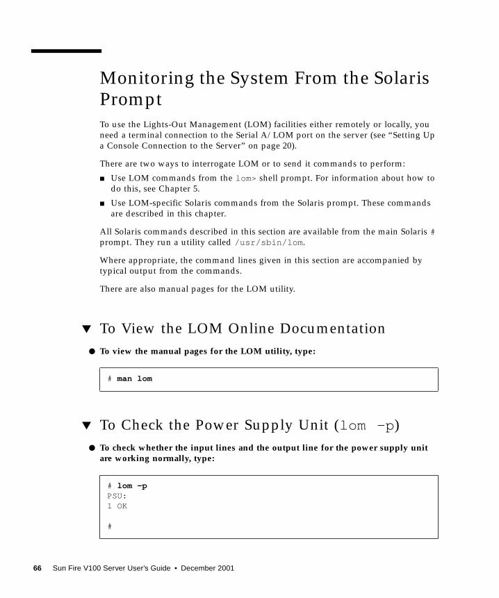
▼ To View the Configuration of LOM
● To view the settings of all the configurable variables for the LOM device, type:
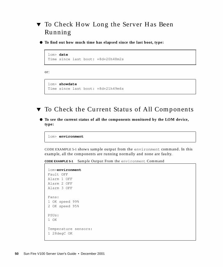
▼ To View All the Status Data Stored by LOM,
Plus Details of the Device’s Own Configuration
● Type:
Code example 6-1 gives sample output of this command.
# lom -cLOMlite configuration settings:serial escape character=#serial event reporting=defaultEvent reporting level=fatal, warning & informationSerial security=enabledDisable watchdog on break=disabledAutomatic return to console=disabledalarm3 mode=watchdogfirmware version=3.0firmware checksum=2983product revision=0.0product ID=Sun Fire 100#
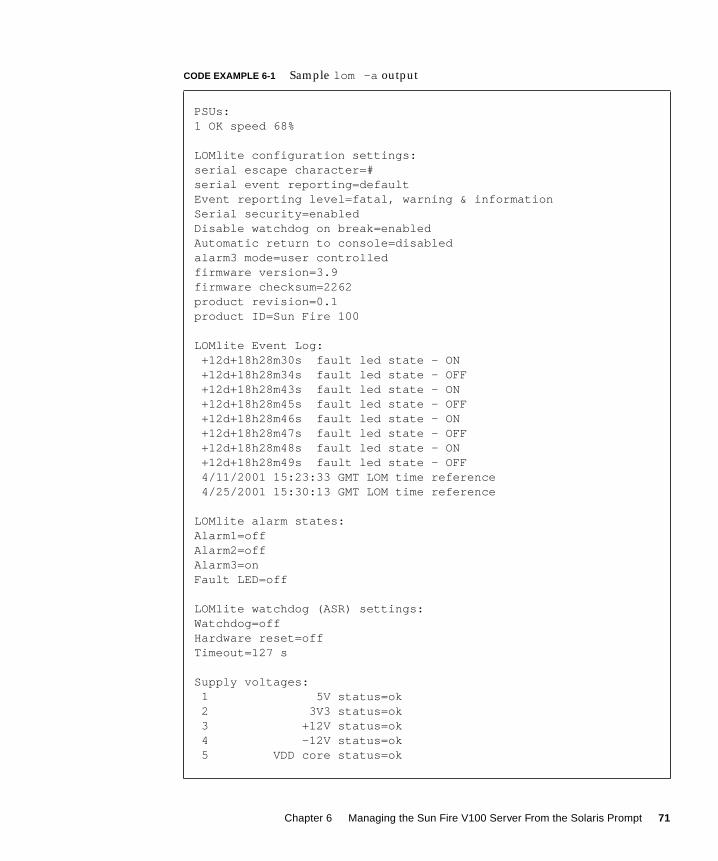
# lom -a
CODE EXAMPLE 6-1 Sample lom -a output
PSUs:1 OK
Fans:
70 Sun Fire V100 Server User’s Guide • December 2001
1 OK speed 68%
LOMlite configuration settings:serial escape character=#serial event reporting=defaultEvent reporting level=fatal, warning & informationSerial security=enabledDisable watchdog on break=enabledAutomatic return to console=disabledalarm3 mode=user controlledfirmware version=3.9firmware checksum=2262product revision=0.1product ID=Sun Fire 100
LOMlite Event Log: +12d+18h28m30s fault led state - ON +12d+18h28m34s fault led state - OFF +12d+18h28m43s fault led state - ON +12d+18h28m45s fault led state - OFF +12d+18h28m46s fault led state - ON +12d+18h28m47s fault led state - OFF +12d+18h28m48s fault led state - ON +12d+18h28m49s fault led state - OFF 4/11/2001 15:23:33 GMT LOM time reference 4/25/2001 15:30:13 GMT LOM time reference
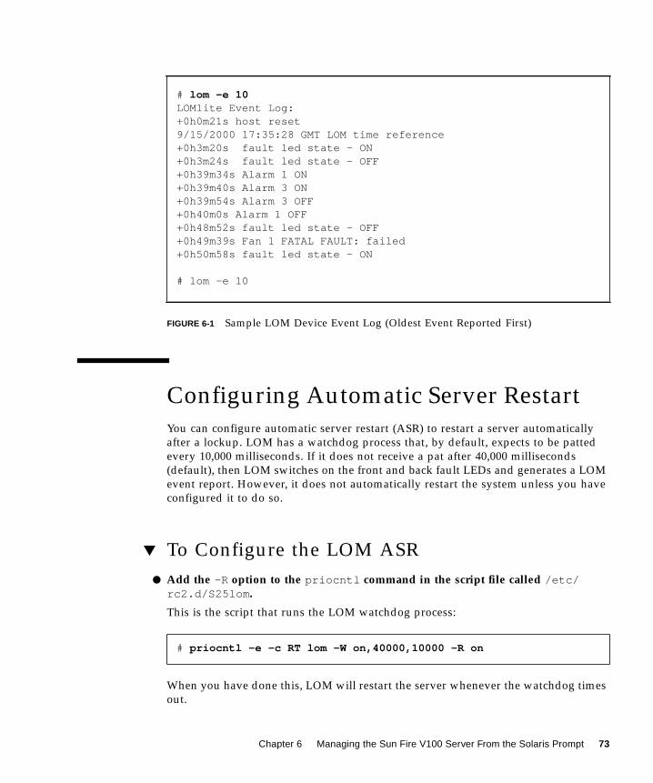
You can configure automatic server restart (ASR) to restart a server automatically
after a lockup. LOM has a watchdog process that, by default, expects to be patted
every 10,000 milliseconds. If it does not receive a pat after 40,000 milliseconds
(default), then LOM switches on the front and back fault LEDs and generates a LOM
event report. However, it does not automatically restart the system unless you have
configured it to do so.
▼ To Configure the LOM ASR
● Add the -R option to the priocntl command in the script file called /etc/rc2.d/S25lom .
This is the script that runs the LOM watchdog process:
When you have done this, LOM will restart the server whenever the watchdog times
out.
# lom -e 10LOMlite Event Log:+0h0m21s host reset9/15/2000 17:35:28 GMT LOM time reference+0h3m20s fault led state - ON+0h3m24s fault led state - OFF+0h39m34s Alarm 1 ON+0h39m40s Alarm 3 ON+0h39m54s Alarm 3 OFF+0h40m0s Alarm 1 OFF+0h48m52s fault led state - OFF+0h49m39s Fan 1 FATAL FAULT: failed+0h50m58s fault led state - ON
# lom -e 10
# priocntl -e -c RT lom -W on,40000,10000 -R on
Chapter 6 Managing the Sun Fire V100 Server From the Solaris Prompt 73
You can turn the option on and off from the Solaris command prompt. For more
information, see “To Set the Hardware Reset Option From a Script or Command
(lom -R on)” on page 75.
However, as long as you have the -R on option set in /etc/rc2.d/S25lom , the
Hardware Reset option will always be enabled when you start the system.
Enabling the LOM Watchdog Process From Your
Own Script or Command (lom -W on )
Note – You do not normally need to do this. If you want to configure LOM to
perform an automatic server restart after a lockup, see “To Configure the LOM ASR”
on page 73. Use the lom -W on option on the command line or in another script file
only if you have removed the
/etc/rc2.d/S25lom script.
By default, the LOM watchdog process is enabled, and if you type
lom -W on while the watchdog process is already running, the command will have
no effect. You can run this command only if you have removed the
/etc/rc2.d/S25lom script file, or if you have turned the watchdog off manually
by using the lom -W off command.
The default priocntl command is:
priocntl -e -c RT lom -W on,40000,10000
The number 40,000 on this command line indicates the watchdog’s timeout period in
milliseconds; you can specify a different number. The number 10,000 indicates its pat
interval in milliseconds; again, you can specify a different number.
Note – Do not specify a watchdog timeout period of less than 5000 milliseconds. If
you do, the watchdog times out frequently even though the server has not locked
up.
If the watchdog process times out (in other words, if it does not receive its expected
pat), the LOM device will turn on the server’s front and back Fault LEDs and
generate a LOM event report. However, it will not automatically reset the system. To
make it reset the system, you must use the -R option. For more information, see “To
Set the Hardware Reset Option From a Script or Command (lom -R on)” on page 75.
74 Sun Fire V100 Server User’s Guide • December 2001
● If you have no LOM watchdog process running already and you want the processto run, type the following, or add it to another script file:
● If you want the LOM device to perform an automatic server restart after a lockup,you must include the -R on option in the command, as follows:
Note – Unless you include the lom -W on and -R on options in a script file, you
must run the lom command every time you reboot the system if you want to use the
automatic server restart facility. Otherwise the watchdog will not run, and the server
will not reset after a lockup.
▼ To Set the Hardware Reset Option From a
Script or Command (lom -R on )
To make the LOM device’s watchdog process trigger an automatic server restart
(ASR) after a lockup, add the -R on option to the command in your
/etc/rc2.d/S25lom script file. This is the script that runs the watchdog. For
instructions about how to do this, see “To Configure the LOM ASR” on page 73.
However, if for any reason you are not using the script file provided with your
system (/etc/rc2.d/S25lom ) but have instead enabled the watchdog from the
command line or from another script file, you can turn the Hardware reset option
on.
● To turn the Hardware reset option on, type the following at the command line:
● To turn the Hardware reset option off from the command line,type:
# lom -W on,40000,10000
# lom -W on,40000,10000 -R on
# lom -R on
# lom -R off
Chapter 6 Managing the Sun Fire V100 Server From the Solaris Prompt 75
Other LOM Tasks You Can PerformFrom the Solaris Prompt
This section describes how to:
■ Turn the alarms and Fault LEDs on and off with the lom command.
■ Change the first character of the lom escape sequence.
■ Stop LOM sending reports to the Serial A/LOM port.
■ Remove driver protection from the device driver.
■ Make the LOM interface backward compatible.
■ Upgrade LOM firmware.
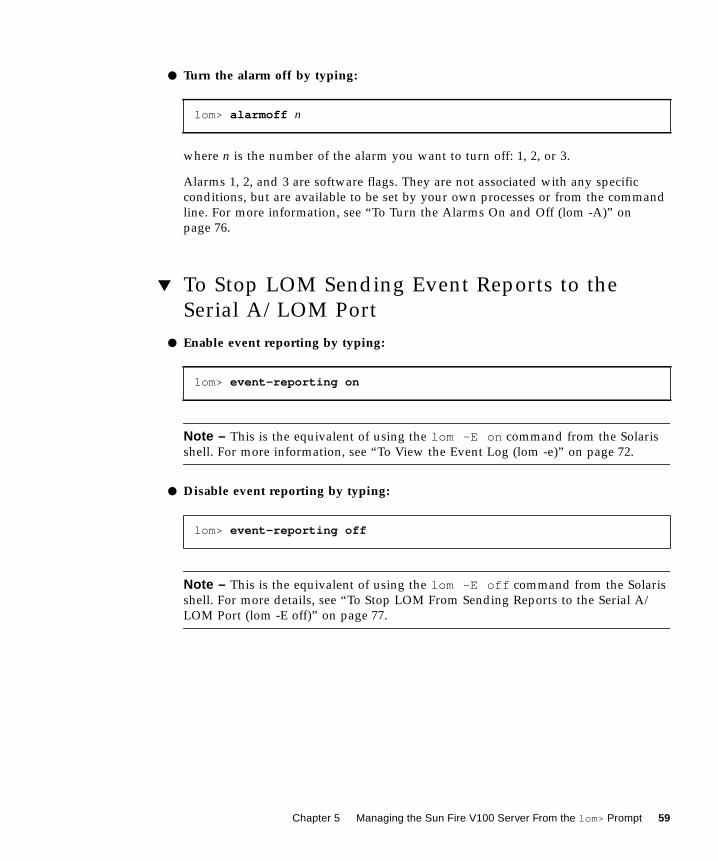
▼ To Turn the Alarms On and Off (lom -A )
There are three alarms associated with LOM. They are not associated with specific
conditions but are software flags that can be set either by your own processes or
from the command line.
● To turn an alarm on from the command line, type:
where n is the number of the alarm you want to set: 1, 2, or 3.
● To turn the alarm off from the command line, type:
where n is the number of the alarm you want to turn off: 1, 2, or 3.
▼ To Turn the Fault LED On and Off (lom -F )
● To turn the Fault LED on, type:
# lom -A on, n
# lom -A off, n
# lom -F on
76 Sun Fire V100 Server User’s Guide • December 2001
● To turn the Fault LED off, type:
▼ To Change the First Character of the Sequence
for Escaping to the lom> Prompt (lom -X )
The character sequence #. (hash, dot) enables you to exit the Solaris prompt to the
lom> prompt.
● To change the first character of this default lom escape sequence, type:
where x is the alphanumeric character you want to use instead of #.
Note – If you are at the console and you type the first character of the LOM escape
sequence (by default this is #), there is a delay of one second before the character
appears on the screen. This is because the system waits to see if you type the dot (.)
character next. If you do, the lom> prompt appears. If you do not, the # character
appears. If you want to change the LOM escape character, use a character that is not
included in any console commands; otherwise the delay between your striking the
key and the character appearing on the screen may affect your typing at the console.
▼ To Stop LOM From Sending Reports to the Serial
A/LOM Port (lom -E off )
LOM event reports can interfere with information you are attempting to send or
receive on the Serial A/LOM port. By default, the Serial A/LOM port is shared by
the console and LOM. LOM interrupts the console whenever it needs to send an
event report. To prevent LOM from interrupting the console on Serial A/LOM, turn
serial event reporting off.
● To stop LOM from sending reports to the Serial A/LOM port, type:
# lom -F off
# lom -X x
# lom -E off
Chapter 6 Managing the Sun Fire V100 Server From the Solaris Prompt 77
● To turn serial event reporting on again, type:
If you want to dedicate the Serial A/LOM port to the LOM device and you want to
use the Serial B port as your console port, see “To Dedicate Serial A/LOM to LOM”
on page 60.
▼ To Make the LOM Interface Backward
Compatible (lom -B )
If you have scripts written to the LOMlite interface on the Netra T1 Model 100/105
server or the Netra t 1400/1405 server and you want to use these scripts on the Sun
Fire V100 server, you can add file system links that make this possible.
● Type:
When you have done this, you will be able to use the old scripts on the new system.
▼ To Upgrade LOM Firmware
(lom -G default )
To upgrade the firmware for LOM, obtain the new firmware package from the
SunSolveSM website (http://sunsolve.sun.com ) or from your local Sun sales
representative, and type the following:
Note – LOM firmware upgrades are released as patches and include detailed
installation instructions.
# lom -E on
# lom -B
# lom -G default
78 Sun Fire V100 Server User’s Guide • December 2001
PART III Maintenance and Troubleshooting
CHAPTER 7
Interpreting the LEDs
This chapter describes the location and function of the warning LEDs on the server,
and contains the following section:
■ “Interpreting the Front- and Back-Panel LEDs” on page 82
81
Interpreting the Front- and Back-PanelLEDs
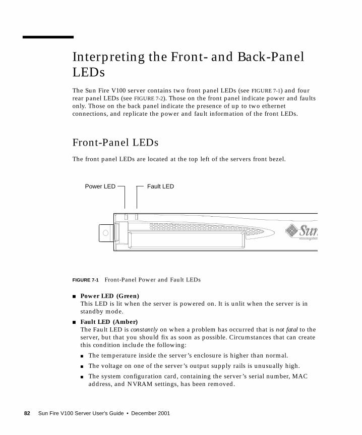
The Sun Fire V100 server contains two front panel LEDs (see FIGURE 7-1) and four
rear panel LEDs (see FIGURE 7-2). Those on the front panel indicate power and faults
only. Those on the back panel indicate the presence of up to two ethernet
connections, and replicate the power and fault information of the front LEDs.
Front-Panel LEDs
The front panel LEDs are located at the top left of the servers front bezel.
FIGURE 7-1 Front-Panel Power and Fault LEDs
■ Power LED (Green)This LED is lit when the server is powered on. It is unlit when the server is in
standby mode.
■ Fault LED (Amber)The Fault LED is constantly on when a problem has occurred that is not fatal to the
server, but that you should fix as soon as possible. Circumstances that can create
this condition include the following:
■ The temperature inside the server’s enclosure is higher than normal.
■ The voltage on one of the server’s output supply rails is unusually high.
■ The system configuration card, containing the server’s serial number, MAC
address, and NVRAM settings, has been removed.
Fault LEDPower LED
82 Sun Fire V100 Server User’s Guide • December 2001
■ The LOM watchdog has timed out, indicating that the server has locked up.
You can configure the server to restart automatically after a lockup (see
Chapter 6).
The Fault LED flashes when a problem has occurred that is fatal to the server.
Circumstances that cause the Fault LED to flash include the following:
■ The speed of the fan inside the server is too low.
■ The temperature inside the server’s enclosure is too high. By default, this
causes the server to shut down. For information about configuring the server
not to shut down in this condition, see Appendix B.
■ The voltage on one of the server’s output supply rails is too high. By default,
this causes the server to shut down. For information about configuring the
server not to shut down in this condition, see Appendix B.
■ The temperature inside the CPU is too high. This causes the server to shut
down.
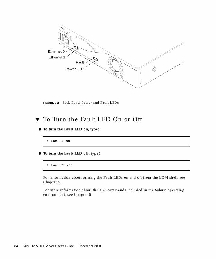
Back-Panel LEDs
The four back panel LEDs convey the information listed below. For the location of
the LEDS on the server, see FIGURE 7-2.
■ Ethernet port 0Lights to indicate link status with dmfe0.
■ Ethernet port 1Lights to indicate link status with dmfe1.
■ Fault LEDThis mirrors the Fault LED on the front panel.
■ Power LEDThis mirrors the Power LED on the front panel.
Chapter 7 Interpreting the LEDs 83
FIGURE 7-2 Back-Panel Power and Fault LEDs
▼ To Turn the Fault LED On or Off
● To turn the Fault LED on, type:
● To turn the Fault LED off, type:
For information about turning the Fault LEDs on and off from the LOM shell, see
Chapter 5.
For more information about the lom commands included in the Solaris operating
environment, see Chapter 6.
# lom -F on
# lom -F off
Power LED
FaultEthernet 1
Ethernet 0
84 Sun Fire V100 Server User’s Guide • December 2001
CHAPTER 8
Removing and ReplacingComponents
This chapter details the procedures for moving the system configuration card from
one server to another, and for changing replaceable components. It contains the
following sections:
■ “Adding Components or Replacing A Server” on page 86
■ “Replacing the System Configuration Card” on page 86
■ “Adding or Changing Internal Components” on page 87
■ “Memory Installation and Removal” on page 91
■ “Installing and Removing the Hard Disk Drive” on page 92
85
Adding Components or Replacing AServer
For a list of components that are available for the Sun Fire V100 server, see “Optional
Components” on page 4. If there is a fault with any of the components listed below,
replace the whole server. Should you need to do this, contact your Sun sales
representative.
■ Motherboard
■ Processor
■ Power Supply Unit
■ Fan
■ CD-ROM drive
The server contains a memory card called the system configuration card. The card
contains the following data:
■ the only copy of NVRAM
■ IDPROM
■ host ID
■ MAC address
Replacing the System ConfigurationCard
The card is removable so that you can transfer the host ID and configuration data
onto a new server, allowing quick and easy server replacement.
▼ To Swap the System Configuration Card (SCC)
Between Servers
1. Make sure that both Sun Fire V100 servers are powered down.
2. Remove the zip ties securing the system configuration cards in both servers, andremove the cards.
3. Insert the system configuration card from the old server into the new one.
86 Sun Fire V100 Server User’s Guide • December 2001
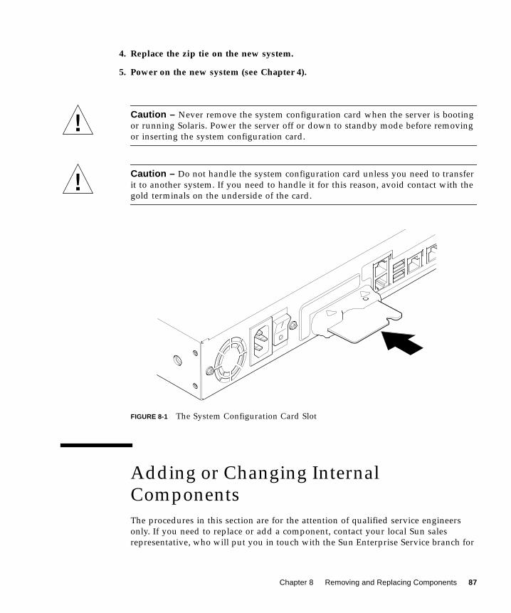
4. Replace the zip tie on the new system.
5. Power on the new system (see Chapter 4).
Caution – Never remove the system configuration card when the server is booting
or running Solaris. Power the server off or down to standby mode before removing
or inserting the system configuration card.
Caution – Do not handle the system configuration card unless you need to transfer
it to another system. If you need to handle it for this reason, avoid contact with the
gold terminals on the underside of the card.
FIGURE 8-1 The System Configuration Card Slot
Adding or Changing InternalComponents
The procedures in this section are for the attention of qualified service engineers
only. If you need to replace or add a component, contact your local Sun sales
representative, who will put you in touch with the Sun Enterprise Service branch for
Chapter 8 Removing and Replacing Components 87
your area. You can then arrange to return the system to Sun for repair under the
terms of your warranty or you can order the components and have them installed by
your own qualified service engineers.
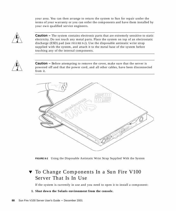
Caution – The system contains electronic parts that are extremely sensitive to static
electricity. Do not touch any metal parts. Place the system on top of an electrostatic
discharge (ESD) pad (see FIGURE 8-2). Use the disposable antistatic wrist strap
supplied with the system, and attach it to the metal base of the system before
touching any of the internal components.
Caution – Before attempting to remove the cover, make sure that the server is
powered off and that the power cord, and all other cables, have been disconnected
from it.
FIGURE 8-2 Using the Disposable Antistatic Wrist Strap Supplied With the System
▼ To Change Components In a Sun Fire V100
Server That Is In UseIf the system is currently in use and you need to open it to install a component:
1. Shut down the Solaris environment from the console.
88 Sun Fire V100 Server User’s Guide • December 2001
2. Hold the On/Standby switch in the Standby position for more than four secondsto put the server in standby mode.
3. Disconnect the power cord.
4. Disconnect all other cables.
5. If the system is installed in a rack or cabinet, remove it.
▼ To Remove the Top Cover■ If the Sun Fire V100 server is not in use, go straight to step 1.
■ If the server is already in use, see “To Change Components In a Sun Fire V100
Server That Is In Use” on page 88.
FIGURE 8-3 Removing the Top Cover
1. Place the unit on an ESD surface and attach an antistatic wrist strap (seeFIGURE 8-2).
2. Unscrew the captive screw from the back of the unit (see FIGURE 8-3).
Chapter 8 Removing and Replacing Components 89
3. Slide the top cover back until the arrow on the cover lines up with the arrow onthe server body.
4. Lift the cover up and off.
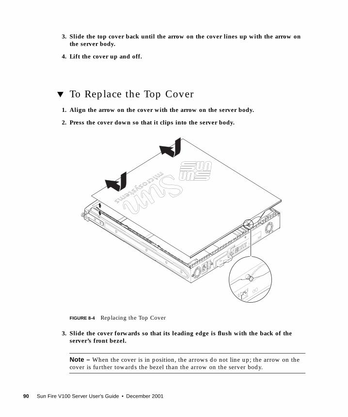
▼ To Replace the Top Cover
1. Align the arrow on the cover with the arrow on the server body.
2. Press the cover down so that it clips into the server body.
FIGURE 8-4 Replacing the Top Cover
3. Slide the cover forwards so that its leading edge is flush with the back of theserver’s front bezel.
Note – When the cover is in position, the arrows do not line up; the arrow on the
cover is further towards the bezel than the arrow on the server body.
90 Sun Fire V100 Server User’s Guide • December 2001
4. Tighten the captive screw on the back of the unit.
Memory Installation and Removal
There are four industry standard PC133 memory module sockets on the Sun Fire
V100 server’s system board. To see the location of the memory modules inside the
server, see FIGURE 8-5 or the underside of the server’s top cover.
▼ To Install and Remove Memory■ If the server is not in use, go straight to Step 1.
■ If the server is already in use, see “To Change Components In a Sun Fire V100
Server That Is In Use” on page 88.
1. Place the unit on an ESD surface and attach an antistatic wrist strap (seeFIGURE 8-2)
2. Remove the server’s top cover (see “To Remove the Top Cover” on page 89).
3. Insert the memory module in the next vacant DIMM socket.
The memory slots are numbered 3, 2, 1, 0. Add DIMMS in that order.
FIGURE 8-5 DIMM Insertion and Removal Sequence
4. Press the memory module until the latches at the sides of the socket click intoplace.
3 2
10
3210
Remove in this order
Add in this order
Chapter 8 Removing and Replacing Components 91
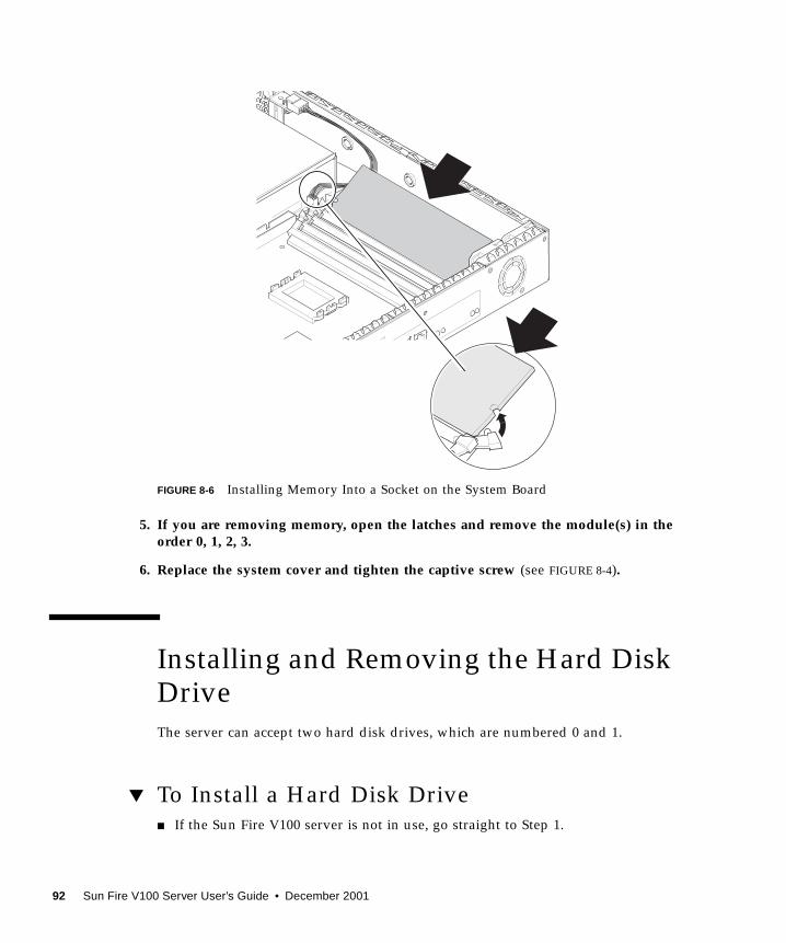
FIGURE 8-6 Installing Memory Into a Socket on the System Board
5. If you are removing memory, open the latches and remove the module(s) in theorder 0, 1, 2, 3.
6. Replace the system cover and tighten the captive screw (see FIGURE 8-4).
Installing and Removing the Hard DiskDrive
The server can accept two hard disk drives, which are numbered 0 and 1.
▼ To Install a Hard Disk Drive■ If the Sun Fire V100 server is not in use, go straight to Step 1.
92 Sun Fire V100 Server User’s Guide • December 2001
■ If the server is already in use, see “To Change Components In a Sun Fire V100
Server That Is In Use” on page 88.
1. Place the unit on an ESD surface and attach an antistatic wrist strap (seeFIGURE 8-2).
2. Remove the server’s top cover (see “To Remove the Top Cover” on page 89).
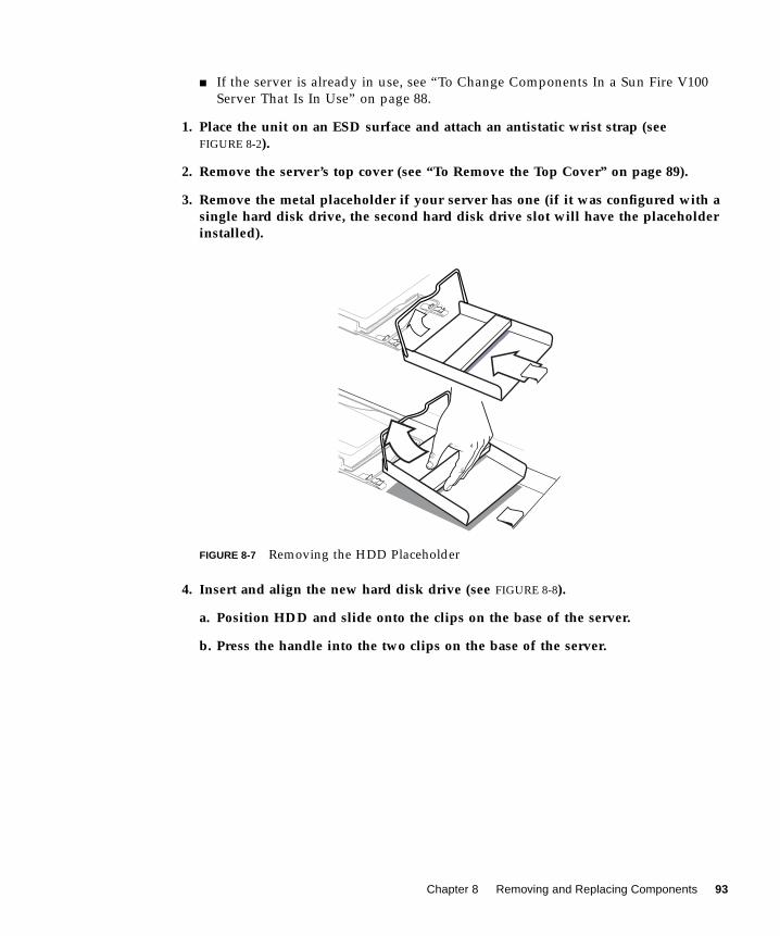
3. Remove the metal placeholder if your server has one (if it was configured with asingle hard disk drive, the second hard disk drive slot will have the placeholderinstalled).
FIGURE 8-7 Removing the HDD Placeholder
4. Insert and align the new hard disk drive (see FIGURE 8-8).
a. Position HDD and slide onto the clips on the base of the server.
b. Press the handle into the two clips on the base of the server.
Chapter 8 Removing and Replacing Components 93
FIGURE 8-8 Installing a Hard Disk Drive
5. Attach the power and data cables (see FIGURE 8-8).
6. Replace the system cover and tighten the captive screw (see FIGURE 8-4).
▼ To Remove a Hard Disk Drive■ If the server is not in use, go straight to Step 1.
■ If the server is already in use, see “To Change Components In a Sun Fire V100
Server That Is In Use” on page 88.
1. Place the unit on an ESD surface and attach an antistatic wrist strap (seeFIGURE 8-2).
2. Remove the server’s top cover (see “To Remove the Top Cover” on page 89).
3. Disconnect the data and power cables.
Step 4a
Step 4b
94 Sun Fire V100 Server User’s Guide • December 2001
4. Unfasten the hard disk drive’s handle from the two clips securing it.
5. Slide the hard disk drive until it is free from the clips on the base of the server.
6. Lift the hard disk drive up and out of the server.
Chapter 8 Removing and Replacing Components 95
96 Sun Fire V100 Server User’s Guide • December 2001
CHAPTER 9
Reinstalling the Solaris OperatingEnvironment
This chapter explains how to reinstall the Solaris operating environment onto the
Sun Fire V100 server. It contains the following sections:
■ “Reinstalling the Solaris Operating Environment” on page 98
■ “Reinstalling the Lights-Out Management Software” on page 98
97
Reinstalling the Solaris OperatingEnvironment
The Sun Fire V100 server is supplied with the Solaris operating environment
preinstalled.
If for any reason you decide to reinstall the Solaris operating environment (for
example, if you need to repartition your root disk or recover from a failure) follow
the instructions in the Solaris Installation Guide (806-0955-10) and the Solaris AdvancedInstallation Guide (806-0957-10).
Reinstalling the Lights-Out ManagementSoftware
If you reinstall the Solaris operating environment and you intend to use the Lights-
Out Management (LOM) facilities, you must re-install the Lights-Out Management
software from the CD entitled Software Supplement for the Solaris OperatingEnvironment. This CD is included among the CDs supplied with Solaris.
If you do not reinstall the LOM software as described here, the LOM facilities will
not be available and layered applications that are dependent on them (for example,
the Sun Management Center software) will not function correctly. To reinstall LOM,
refer to the Sun Hardware Platform Guide.
98 Sun Fire V100 Server User’s Guide • December 2001
CHAPTER 10
Troubleshooting
This chapter describes the diagnostic tools you can use with the Sun Fire V100
server, lists some of the problems you might encounter when setting up or using a
server, and gives information to help fix those problems. The information is
contained in the following sections:
■ “Diagnostic Tools” on page 100
■ “Problems You Might Encounter” on page 105
■ “Frequently Asked Questions” on page 108
99
Diagnostic Tools
The following troubleshooting tools are available for the servers:
■ Power On Self Test (POST) Diagnostics
■ OpenBoot Diagnostics (OBDiag)
■ SunVTS
POST Diagnostics
To view Power On Self Test (POST) diagnostic and error messages you need to have
a serial connection set up to the server. For more information, see “Setting Up a
Console Connection to the Server” on page 20.
If the OpenBoot PROM (OBP) variable diag-switch? is set to true , then POST
diagnostics will run automatically when you power on the server. However, the
default setting for diag-switch? is false .
To initialize POST diagnostics, you need to set the diag-switch? variable to trueand diag-level to max or min , and then power cycle the server. From the okprompt:
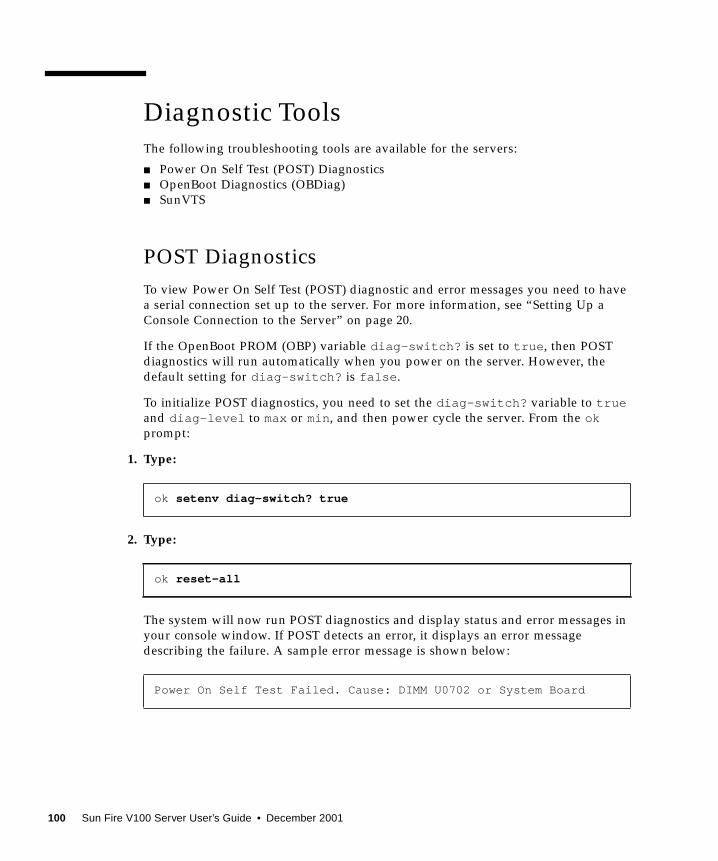
1. Type:
2. Type:
The system will now run POST diagnostics and display status and error messages in
your console window. If POST detects an error, it displays an error message
describing the failure. A sample error message is shown below:
ok setenv diag-switch? true
ok reset-all
Power On Self Test Failed. Cause: DIMM U0702 or System Board
100 Sun Fire V100 Server User’s Guide • December 2001
OpenBoot Diagnostics
Like POST diagnostics, OpenBoot Diagnostics can be run if the diag-switch?variable is set to true .
You can also run OpenBoot Diagnostics interactively and select which tests you want
it to perform. To do so, follow the steps below from the ok prompt.
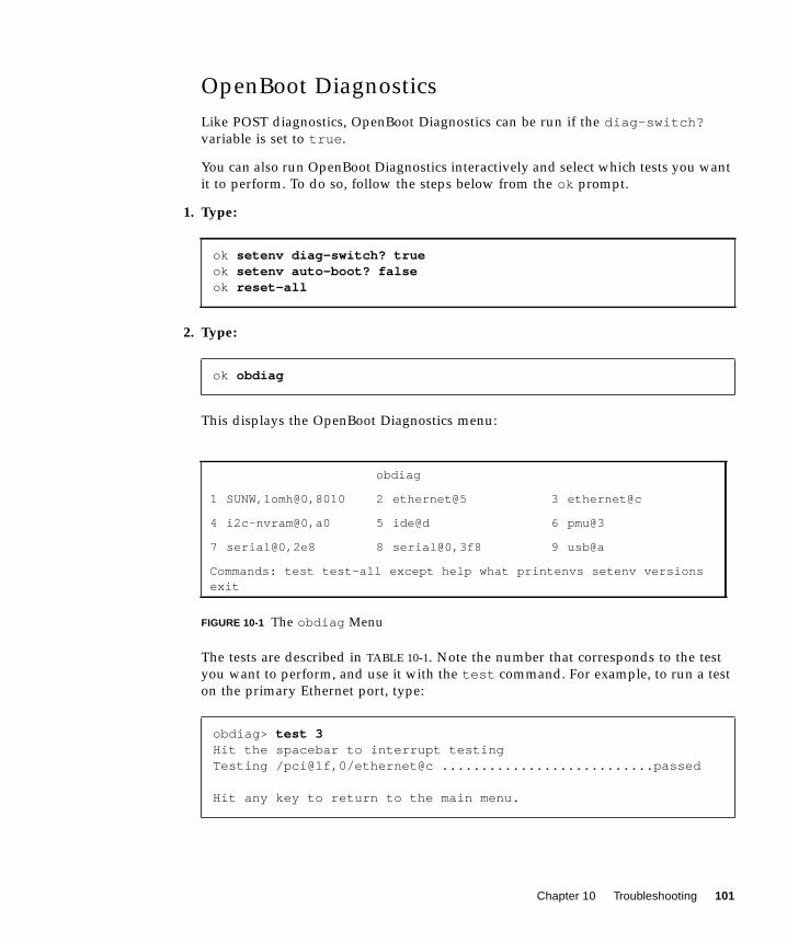
1. Type:
2. Type:
This displays the OpenBoot Diagnostics menu:
FIGURE 10-1 The obdiag Menu
The tests are described in TABLE 10-1. Note the number that corresponds to the test
you want to perform, and use it with the test command. For example, to run a test
on the primary Ethernet port, type:
ok setenv diag-switch? trueok setenv auto-boot? falseok reset-all
ok obdiag
obdiag
1 SUNW,lomh@0,8010 2 ethernet@5 3 ethernet@c
4 i2c-nvram@0,a0 5 ide@d 6 pmu@3
7 serial@0,2e8 8 serial@0,3f8 9 usb@a
Commands: test test-all except help what printenvs setenv versionsexit
obdiag> test 3Hit the spacebar to interrupt testingTesting /pci@1f,0/ethernet@c ...........................passed
Hit any key to return to the main menu.
Chapter 10 Troubleshooting 101
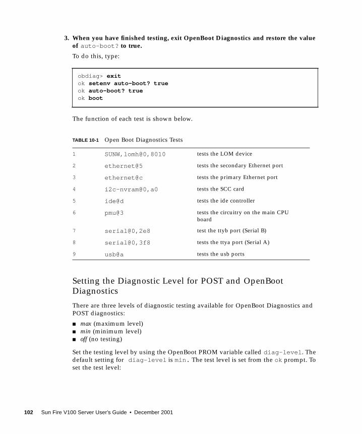
3. When you have finished testing, exit OpenBoot Diagnostics and restore the valueof auto-boot? to true.
To do this, type:
The function of each test is shown below.
Setting the Diagnostic Level for POST and OpenBootDiagnostics
There are three levels of diagnostic testing available for OpenBoot Diagnostics and
POST diagnostics:
■ max (maximum level)
■ min (minimum level)
■ off (no testing)
Set the testing level by using the OpenBoot PROM variable called diag-level . The
default setting for diag-level is min. The test level is set from the ok prompt. To
■ Emissions: The server conforms to EN55022 Class A and FCC Class A.
■ Safety
The system conforms to UL 1950 (3rd edition), EN60950
Operating Power Statistics
* The in-rush current decays to the normal operating current in less than 200 msecs.
Caution – The power supply continues to regulate all outputs for at least 17 ms
after AC power is removed.
Note – Logic ground and chassis ground are connected internally.
TABLE A-2 Operating Power Statistics
Maximum operating current 1.3A @ 100 VAC
Typical operating current See “Calculating Power Consumption” on
page 118
Maximum in-rush
current (cold start)*
40A peak at 115V 25˚C
Maximum in-rush
current (warm start, or upon a restart 20 to
200 msecs after power has been removed*)
100A peak at 115V 25˚C
Operating input voltage range 90 to 264 Vrms
Voltage frequency range 47 to 63 Hz
Power factor 0.9 to 0.99
Maximum volt-ampere rating 130 VA
BTU/hr 500 MHz processor: 148 (min), 280 (max).
Appendix A Physical and Environmental Specifications 117
Note – Power from the standby output is available whenever input power is
connected.
Calculating Power Consumption
A Sun Fire V100 server containing two disk drives has an estimated current
requirement of approximately 1 amp.
TABLE A-3 shows the estimated power consumed by the individual components in a
fully powered system. However, when you are calculating the power requirements
for your system, you must allow for 63 percent PSU efficiency. To perform this
calculation, add the figures for each component installed in the system, then divide
the result by 0.63.
Note – To calculate the total power requirement for several servers installed in a
single rack or cabinet, add the individual power requirement figure for each server
installed.
Calculating Heat Dissipation
To calculate the heat generated by a server so that you can estimate the heat your
cooling system must dissipate, convert the figure for the system’s power
requirement from watts to BTU/hr. A general formula for doing this is to multiply
the figure for the power requirement by 3.415.
TABLE A-3 Estimated Power Consumption of Server Components
Component Sun Fire V100
Base system 22.5W
Memory (per DIMM) 4.59W (256 Mbytes, burst mode)
Hard disk drive 6.5W (40 Gbyte/7200 rpm, idle)
118 Sun Fire V100 Server User’s Guide • December 2001
APPENDIX B
Configuring LOM Driver
This appendix describes the parameters that you can use to configure the LOM
driver, and contains the following sections:
■ “The LOM Device Driver and Script Files” on page 120
■ “Configuring the LOM Device Driver” on page 121
119
The LOM Device Driver and Script Files
The LOM driver software included in the Solaris 8 (10/00) operating environment is
as follows:
■ /platform/sun4u/kernel/drv/lom (the lom driver [32-bit])
■ /platform/sun4u/kernel/drv/sparcv9/lom (the lom driver [64-bit])
■ /platform/sun4u/kernel/drv/lom.conf (the driver configuration file)
The driver is started by the following three scripts in the Solaris 8 (10/00)
environment:
■ /etc/init.d/lom
■ /etc/rc2.d/S25lom
■ /etc/rc0.d/K80lom
This appendix describes the driver parameters you can set in the lom.confconfiguration file. Some of these parameters are configurable by means of the LOM-
specific Solaris commands described in Chapter 6.
120 Sun Fire V100 Server User’s Guide • December 2001
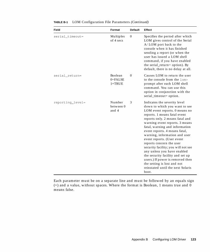
Configuring the LOM Device Driver
The full list of parameters you can set in this file is given in TABLE B-1.
TABLE B-1 LOM Configuration File Parameters
Field Format Default Effect
wdog_reset= Boolean
0=FALSE
1=TRUE
0 Causes LOM to reset the server
after a watchdog timeout.
Setting this to 1 is equivalent to
using the lom -R on command
described in Chapter 6.
wdog_alarm3= Boolean
0=FALSE
1=TRUE
0 Turns on software alarm 3 when
the LOM watchdog times out.
Setting this to 1 is equivalent to
using the lom -A on,3command described in
Chapter 6.
serial_events= 0=OFF
1=ON
2=ON
WHEN
DRIVER
NOT
LOADED
2 Causes LOM to report events
over the serial connection.
Setting this parameter to 0
means that no events will be
reported over the serial
connection. Setting it to 1 means
that events will be reported
over the serial connection as
well as to syslogd ; this is
equivalent to lom -E on . If
you have dedicated the Serial
A/LOM port to LOM, you need
to set this parameter to 1. It
ensures that you receive all
event reports at the terminal
you have connected to Serial A/
LOM. Finally, setting the
parameter to 2 means that
events will be reported over the
serial connection but only when
the driver is not running (when
it is running they will be
reported to syslogd , although
Fatal and Warning messages
will still go to Serial A/LOM).
Appendix B Configuring LOM Driver 121
disable_wdog_on_break= Boolean
0=FALSE
1=TRUE
1 Causes LOM to disable its
watchdog if it detects a break
signal on the Serial A/LOM
port.
disable_wdog_on_panic= Boolean
0=FALSE
1=TRUE
1 Causes LOM to try to disable its
watchdog after a system
“panic”.
faulty_voltage_shutdown= Boolean
0=FALSE
1=TRUE
1 Causes LOM to attempt first to
shut down the system and, if
that fails, to power off the
system in the event of a
problem with the supply rails.
enclosure_warning_temp= oC 67 Specifies the temperature at
which LOM generates an
overtemperature event.
over_temperature_shutdown= Boolean
0=FALSE
1=TRUE
1 Causes LOM to attempt to shut
down the system, or to power it
off, if the enclosure temperature
exceeds the level specified for
the enclosure_shutdown_temp
parameter.
enclosure_shutdown_temp= oC 72 Specifies the enclosure