Sun Microsystems, Inc. 901 San Antonio Road Palo Alto, CA 94303 U.S.A. 650-960-1300 Send comments about this document to: [email protected]Sun StorEdge ™ T3 Disk Tray Installation, Operation, and Service Manual Part No. 806-1062-11 July 2000, Revision A
Transcript
Sun Microsystems, Inc.901 San Antonio RoadPalo Alto, CA 94303U.S.A. 650-960-1300
Sun StorEdge™ T3 Disk TrayInstallation, Operation, and
Service Manual
Part No. 806-1062-11July 2000, Revision A
PleaseRecycle
Copyright 2000 Sun Microsystems, Inc., 901 San Antonio Road • Palo Alto, CA 94303-4900 USA. All rights reserved.
This product or document is protected by copyright and distributed under licenses restricting its use, copying, distribution, and decompilation.
No part of this product or document may be reproduced in any form by any means without prior written authorization of Sun and its licensors,
if any. Third-party software, including font technology, is copyrighted and licensed from Sun suppliers.
Parts of the product may be derived from Berkeley BSD systems, licensed from the University of California. UNIX is a registered trademark in
the U.S. and other countries, exclusively licensed through X/Open Company, Ltd. For Netscape Communicator™, the following notice applies:
Copyright 1995 Netscape Communications Corporation. All rights reserved.
Sun, Sun Microsystems, the Sun logo, AnswerBook2, docs.sun.com, SunSolve, JumpStart, StorTools, Sun StorEdge, and Solaris are trademarks,
registered trademarks, or service marks of Sun Microsystems, Inc. in the U.S. and other countries. All SPARC trademarks are used under license
and are trademarks or registered trademarks of SPARC International, Inc. in the U.S. and other countries. Products bearing SPARC trademarks
are based upon an architecture developed by Sun Microsystems, Inc.
The OPEN LOOK and Sun™ Graphical User Interface was developed by Sun Microsystems, Inc. for its users and licensees. Sun acknowledges
the pioneering efforts of Xerox in researching and developing the concept of visual or graphical user interfaces for the computer industry. Sun
holds a non-exclusive license from Xerox to the Xerox Graphical User Interface, which license also covers Sun’s licensees who implement OPEN
LOOK GUIs and otherwise comply with Sun’s written license agreements.
RESTRICTED RIGHTS: Use, duplication, or disclosure by the U.S. Government is subject to restrictions of FAR 52.227-14(g)(2)(6/87) and
FAR 52.227-19(6/87), or DFAR 252.227-7015(b)(6/95) and DFAR 227.7202-3(a).
DOCUMENTATION IS PROVIDED “AS IS” AND ALL EXPRESS OR IMPLIED CONDITIONS, REPRESENTATIONS AND WARRANTIES,
INCLUDING ANY IMPLIED WARRANTY OF MERCHANTABILITY, FITNESS FOR A PARTICULAR PURPOSE OR NON-
INFRINGEMENT, ARE DISCLAIMED, EXCEPT TO THE EXTENT THAT SUCH DISCLAIMERS ARE HELD TO BE LEGALLY INVALID.
Copyright 2000 Sun Microsystems, Inc., 901 San Antonio Road • Palo Alto, CA 94303-4900 Etats-Unis. Tous droits réservés.
Ce produit ou document est protégé par un copyright et distribué avec des licences qui en restreignent l’utilisation, la copie, la distribution, et la
décompilation. Aucune partie de ce produit ou document ne peut être reproduite sous aucune forme, par quelque moyen que ce soit, sans
l’autorisation préalable et écrite de Sun et de ses bailleurs de licence, s’il y en a. Le logiciel détenu par des tiers, et qui comprend la technologie
relative aux polices de caractères, est protégé par un copyright et licencié par des fournisseurs de Sun.
Des parties de ce produit pourront être dérivées des systèmes Berkeley BSD licenciés par l’Université de Californie. UNIX est une marque
déposée aux Etats-Unis et dans d’autres pays et licenciée exclusivement par X/Open Company, Ltd. La notice suivante est applicable à
Netscape Communicator™: Copyright 1995 Netscape Communications Corporation. Tous droits réservés.
Sun, Sun Microsystems, the Sun logo, AnswerBook2, docs.sun.com, SunSolve, JumpStart, StorTools, Sun StorEdge, et Solaris sont des marques
de fabrique ou des marques déposées, ou marques de service, de Sun Microsystems, Inc. aux Etats-Unis et dans d’autres pays. Toutes les
marques SPARC sont utilisées sous licence et sont des marques de fabrique ou des marques déposées de SPARC International, Inc. aux Etats-
Unis et dans d’autres pays. Les produits portant les marques SPARC sont basés sur une architecture développée par Sun Microsystems, Inc.
L’interface d’utilisation graphique OPEN LOOK et Sun™ a été développée par Sun Microsystems, Inc. pour ses utilisateurs et licenciés. Sun
reconnaît les efforts de pionniers de Xerox pour la recherche et le développement du concept des interfaces d’utilisation visuelle ou graphique
pour l’industrie de l’informatique. Sun détient une licence non exclusive de Xerox sur l’interface d’utilisation graphique Xerox, cette licence
couvrant également les licenciés de Sun qui mettent en place l’interface d’utilisation graphique OPEN LOOK et qui en outre se conforment aux
licences écrites de Sun.
CETTE PUBLICATION EST FOURNIE "EN L’ETAT" ET AUCUNE GARANTIE, EXPRESSE OU IMPLICITE, N’EST ACCORDEE, Y COMPRIS
DES GARANTIES CONCERNANT LA VALEUR MARCHANDE, L’APTITUDE DE LA PUBLICATION A REPONDRE A UNE UTILISATION
PARTICULIERE, OU LE FAIT QU’ELLE NE SOIT PAS CONTREFAISANTE DE PRODUIT DE TIERS. CE DENI DE GARANTIE NE
S’APPLIQUERAIT PAS, DANS LA MESURE OU IL SERAIT TENU JURIDIQUEMENT NUL ET NON AVENU.
Regulatory Compliance Statements
Your Sun product is marked to indicate its compliance class:
• Federal Communications Commission (FCC) — USA
• Industry Canada Equipment Standard for Digital Equipment (ICES-003) - Canada
• Voluntary Control Council for Interference (VCCI) — Japan
• Bureau of Standards Metrology and Inspection (BSMI) — Taiwan
Please read the appropriate section that corresponds to the marking on your Sun product before attempting to install theproduct.
FCC Class A Notice
This device complies with Part 15 of the FCC Rules. Operation is subject to the following two conditions:
1. This device may not cause harmful interference.
2. This device must accept any interference received, including interference that may cause undesired operation.
Note: This equipment has been tested and found to comply with the limits for a Class A digital device, pursuant to Part 15 ofthe FCC Rules. These limits are designed to provide reasonable protection against harmful interference when the equipmentis operated in a commercial environment. This equipment generates, uses, and can radiate radio frequency energy, and if it isnot installed and used in accordance with the instruction manual, it may cause harmful interference to radio communications.Operation of this equipment in a residential area is likely to cause harmful interference, in which case the user will be requiredto correct the interference at his own expense.
Shielded Cables: Connections between the workstation and peripherals must be made using shielded cables to comply withFCC radio frequency emission limits. Networking connections can be made using unshielded twisted-pair (UTP) cables.
Modifications: Any modifications made to this device that are not approved by Sun Microsystems, Inc. may void theauthority granted to the user by the FCC to operate this equipment.
FCC Class B Notice
This device complies with Part 15 of the FCC Rules. Operation is subject to the following two conditions:
1. This device may not cause harmful interference.
2. This device must accept any interference received, including interference that may cause undesired operation.
Note: This equipment has been tested and found to comply with the limits for a Class B digital device, pursuant to Part 15 ofthe FCC Rules. These limits are designed to provide reasonable protection against harmful interference in a residentialinstallation. This equipment generates, uses and can radiate radio frequency energy and, if not installed and used inaccordance with the instructions, may cause harmful interference to radio communications. However, there is no guaranteethat interference will not occur in a particular installation. If this equipment does cause harmful interference to radio ortelevision reception, which can be determined by turning the equipment off and on, the user is encouraged to try to correct theinterference by one or more of the following measures:
• Reorient or relocate the receiving antenna.
• Increase the separation between the equipment and receiver.
• Connect the equipment into an outlet on a circuit different from that to which the receiver is connected.
• Consult the dealer or an experienced radio/television technician for help.
Shielded Cables: Connections between the workstation and peripherals must be made using shielded cables in order tomaintain compliance with FCC radio frequency emission limits. Networking connections can be made using unshieldedtwisted pair (UTP) cables.
Modifications: Any modifications made to this device that are not approved by Sun Microsystems, Inc. may void theauthority granted to the user by the FCC to operate this equipment.
iii
ICES-003 Class A Notice - Avis NMB-003, Classe A
This Class A digital apparatus complies with Canadian ICES-003.
Cet appareil numérique de la classe A est conforme à la norme NMB-003 du Canada.
ICES-003 Class B Notice - Avis NMB-003, Classe B
This Class B digital apparatus complies with Canadian ICES-003.
Cet appareil numérique de la classe B est conforme à la norme NMB-003 du Canada.
iv Sun StorEdge T3 Disk Tray Installation, Operation, and Service Manual • July 2000
BSMI Class A Notice
The following statement is applicable to products shipped to Taiwan and marked as Class A on the product compliancelabel.
Regulatory Compliance Statements v
vi Sun StorEdge T3 Disk Tray Installation, Operation, and Service Manual • July 2000
Safety Agency Compliance Statements
Read this section before beginning any procedure. The
following text provides safety precautions to follow when
installing a Sun Microsystems product.
Safety Precautions
For your protection, observe the following safety precautions
when setting up your equipment:
• Follow all cautions and instructions marked on the
equipment.
• Ensure that the voltage and frequency of your power
source match the voltage and frequency inscribed on the
equipment’s electrical rating label.
• Never push objects of any kind through openings in the
equipment. Dangerous voltages may be present.
Conductive foreign objects could produce a short circuit
that could cause fire, electric shock, or damage to your
equipment.
Symbols
The following symbols may appear in this book:
Caution – There is risk of personal injury and
equipment damage. Follow the instructions.
Caution – Hot surface. Avoid contact. Surfaces are
hot and may cause personal injury if touched.
Caution – Hazardous voltages are present. To reduce
the risk of electric shock and danger to personal
health, follow the instructions.
On – Applies AC power to the system.
Depending on the type of power switch your device has, one
of the following symbols may be used:
Off – Removes AC power from the system.
Standby – The On/Standby switch is in the standbyposition.
Modifications to Equipment
Do not make mechanical or electrical modifications to the
equipment. Sun Microsystems is not responsible for
regulatory compliance of a modified Sun product.
Placement of a Sun Product
Caution – Do not block or cover the openings of your
Sun product. Never place a Sun product near a
radiator or heat register. Failure to follow these
guidelines can cause overheating and affect the
reliability of your Sun product.
Caution – The workplace-dependent noise level
defined in DIN 45 635 Part 1000 must be 70Db(A) or
less.
SELV Compliance
Safety status of I/O connections comply to SELV
requirements.
Power Cord Connection
Caution – Sun products are designed to work with
single-phase power systems having a grounded
neutral conductor. To reduce the risk of electric
shock, do not plug Sun products into any other type
of power system. Contact your facilities manager or a
qualified electrician if you are not sure what type of
power is supplied to your building.
Caution – Not all power cords have the same current
ratings. Household extension cords do not have
overload protection and are not meant for use with
computer systems. Do not use household extension
cords with your Sun product.
Caution – Your Sun product is shipped with a
grounding type (three-wire) power cord. To reduce
the risk of electric shock, always plug the cord into a
grounded power outlet.
The following caution applies only to devices with a
Standby power switch:
Caution – The power switches of this product
function as standby type devices only. The power
cords serve as the primary disconnect device for the
system. ALL power cords must be disconnected to
remove power from the product. Be sure to plug the
power cords into a grounded power outlet that is
nearby the system and is readily accessible.
!
!
!
vii
Lithium Battery
Caution – On the system control board, there is a
lithium battery molded into the real-time clock, SGS
No. MK48T59Y, MK48TXXB-XX, MK48T18-XXXPCZ,
M48T59W-XXXPCZ, M4T28 XXYYSHZ or MK48T08.
Batteries are not customer replaceable parts. They
may explode if mishandled. Do not dispose of the
battery in fire. Do not disassemble it or attempt to
recharge it.
Battery Pack
Caution - There is a Nickel Metal Hydride battery in
the product power supply. Panasonic Model
HHR200SCP. There is danger of explosion if the
battery is mishandled or incorrectly replaced.
Replace only with the same type of Sun
Microsystems battery. Do not disassemble it or
attempt to recharge it outside the system. Do not
dispose of the battery in fire. Dispose of thebattery
properly in accordance with local regulations.
System Unit Cover
Caution – Do not operate Sun products without the
top cover in place. Failure to take this precaution
may result in personal injury and system damage.
Laser Compliance Notice
Sun products that use laser technology comply with
Class 1 laser requirements.
Caution – Use of controls, adjustments, or the
performance of procedures other than those specified
herein may result in hazardous radiation exposure.
Einhaltung sicherheitsbehördlicherVorschriften
Auf dieser Seite werden Sicherheitsrichtlinien beschrieben,
die bei der Installation von Sun-Produkten zu beachten sind.
Sicherheitsvorkehrungen
Treffen Sie zu Ihrem eigenen Schutz die folgenden
Sicherheitsvorkehrungen, wenn Sie Ihr Gerät installieren:
• Beachten Sie alle auf den Geräten angebrachten
Warnhinweise und Anweisungen.
• Vergewissern Sie sich, daß Spannung und Frequenz Ihrer
Stromquelle mit der Spannung und Frequenz
übereinstimmen, die auf dem Etikett mit den elektrischen
Nennwerten des Geräts angegeben sind.
• Stecken Sie auf keinen Fall irgendwelche Gegenstände in
Öffnungen in den Geräten. Leitfähige Gegenstände
könnten aufgrund der möglicherweise vorliegenden
gefährlichen Spannungen einen Kurzschluß verursachen,
der einen Brand, Stromschlag oder Geräteschaden
herbeiführen kann.
Symbole
Die Symbole in diesem Handbuch haben folgende
Bedeutung:
Achtung – Gefahr von Verletzung und
Geräteschaden. Befolgen Sie die Anweisungen.
Achtung – Hohe Temperatur. Nicht berühren, da
Verletzungsgefahr durch heiße Oberfläche besteht.
Achtung – Gefährliche Spannungen. Anweisungen
befolgen, um Stromschläge und Verletzungen zu
vermeiden.
Ein – Setzt das System unter Wechselstrom.
Je nach Netzschaltertyp an Ihrem Gerät kann eines der
folgenden Symbole benutzt werden:
Aus – Unterbricht die Wechselstromzufuhr zum
Gerät.
Wartezustand (Stand-by-Position) - Der Ein-/
Wartezustand-Schalter steht auf Wartezustand.
Änderungen an Sun-Geräten.
!
!
!
Class 1 Laser ProductLuokan 1 Laserlaite
Klasse 1 Laser ApparatLaser Klasse 1
!
!
viii Sun StorEdge T3 Disk Tray Installation, Operation, and Service Manual • July 2000
Nehmen Sie keine mechanischen oder elektrischen
Änderungen an den Geräten vor. Sun Microsystems
übernimmt bei einem Sun-Produkt, das geändert wurde,
keine Verantwortung für die Einhaltung behördlicher
Vorschriften.
Aufstellung von Sun-Geräten
Achtung – Um den zuverlässigen Betrieb Ihres Sun-
Geräts zu gewährleisten und es vor Überhitzung zu
schützen, dürfen die Öffnungen im Gerät nicht
blockiert oder verdeckt werden. Sun-Produkte sollten
niemals in der Nähe von Heizkörpern oder
Heizluftklappen aufgestellt werden.
Achtung – Der arbeitsplatzbezogene
Schalldruckpegel nach DIN 45 635 Teil 1000 beträgt
70Db(A) oder weniger.
Einhaltung der SELV-Richtlinien
Die Sicherung der I/O-Verbindungen entspricht den
Anforderungen der SELV-Spezifikation.
Anschluß des Netzkabels
Achtung – Sun-Produkte sind für den Betrieb an
Einphasen-Stromnetzen mit geerdetem Nulleiter
vorgesehen. Um die Stromschlaggefahr zu
reduzieren, schließen Sie Sun-Produkte nicht an
andere Stromquellen an. Ihr Betriebsleiter oder ein
qualifizierter Elektriker kann Ihnen die Daten zur
Stromversorgung in Ihrem Gebäude geben.
Achtung – Nicht alle Netzkabel haben die gleichen
Nennwerte. Herkömmliche, im Haushalt verwendete
Verlängerungskabel besitzen keinen
Überlastungsschutz und sind daher für
Computersysteme nicht geeignet.
Achtung – Ihr Sun-Gerät wird mit einem dreiadrigen
Netzkabel für geerdete Netzsteckdosen geliefert. Um
die Gefahr eines Stromschlags zu reduzieren,
schließen Sie das Kabel nur an eine fachgerecht
verlegte, geerdete Steckdose an.
Die folgende Warnung gilt nur für Geräte mit Wartezustand-
Netzschalter:
Achtung – Die Ein/Aus-Schalter dieses Geräts
schalten nur auf Wartezustand (Stand-By-Modus).
Um die Stromzufuhr zum Gerät vollständig zu
unterbrechen, müssen Sie die Netzkabel aus der
Steckdose ziehen. Alle Netzkabel müssen ausgesteckt
sein, um die Stromverbindung zum Produkt zu
unterbrechen. Schließen Sie die Stecker der Netzkabel
an eine in der Nähe befindliche, frei zugängliche,
geerdete Netzsteckdose an.
Lithiumbatterie
Achtung – Systemsteuerungskarten verfügen über
eine Echtzeituhr mit integrierter Lithiumbatterie
(Teile-Nr. MK48T59Y, MK48TXXB-XX, MK48T18-
XXXPCZ, M48T59W-XXXPCZ, M4T28 XXYYSHZ
oder MK48T08). Diese Batterie darf nur von einem
qualifizierten Servicetechniker ausgewechselt
werden, da sie bei falscher Handhabung explodieren
kann. Werfen Sie die Batterie nicht ins Feuer.
Versuchen Sie auf keinen Fall, die Batterie
auszubauen oder wiederaufzuladen.
Batterien
Achtung – Das Netzteil des Panasonic-Modells
HHR200SCP enthält eine Nickel-Metall-
Hydridbatterie. Werden bei der Behandlung oder
beim Austausch der Batterie Fehler gemacht, besteht
Explosionsgefahr. Tauschen Sie Batterien nur gegen
Batterien gleichen Typs von Sun Microsystems aus.
Demontieren Sie die Batterie nicht, und versuchen Sie
nicht, die Batterie außerhalb des Geräts zu laden.
Werfen Sie die Batterie nicht ins Feuer. Entsorgen Sie
die Batterie ordnungsgemäß entsprechend den vor
Ort geltenden Vorschriften.
Gehäuseabdeckung
Achtung – Bei Betrieb des Systems ohne obere
Abdeckung besteht die Gefahr von Stromschlag und
Systemschäden.
!
! !
!
!
Safety Agency Compliance Statements ix
Einhaltung der Richtlinien für Laser
Sun-Produkte, die mit Laser-Technologie arbeiten,
entsprechen den Anforderungen der Laser Klasse 1.
Warnung – Die Verwendung von anderen
Steuerungen und Einstellungen oder die
Durchfhrung von Prozeduren, die von den hier
beschriebenen abweichen, knnen gefhrliche
Strahlungen zur Folge haben.
Conformité aux normes de sécurité
Ce texte traite des mesures de sécurité qu’il convient de
prendre pour l’installation d’un produit Sun Microsystems.
Mesures de sécurité
Pour votre protection, veuillez prendre les précautions
suivantes pendant l’installation du matériel :
• Suivre tous les avertissements et toutes les instructions
inscrites sur le matériel.
• Vérifier que la tension et la fréquence de la source
d’alimentation électrique correspondent à la tension et à la
fréquence indiquées sur l’étiquette de classification de
l’appareil.
• Ne jamais introduire d’objets quels qu’ils soient dans une
des ouvertures de l’appareil. Vous pourriez vous trouver
en présence de hautes tensions dangereuses. Tout objet
conducteur introduit de la sorte pourrait produire un
court-circuit qui entraînerait des flammes, des risques
d’électrocution ou des dégâts matériels.
Symboles
Vous trouverez ci-dessous la signification des différents
symboles utilisés :
Attention : risques de blessures corporelles et de
dégâts matériels. Veuillez suivre les instructions.
Attention : surface à température élevée. Evitez le
contact. La température des surfaces est élevée et leur
contact peut provoquer des blessures corporelles.
Attention : présence de tensions dangereuses. Pour
éviter les risques d’électrocution et de danger pour la
santé physique, veuillez suivre les instructions.
MARCHE : votre système est sous tension (courant
alternatif).
Un des symboles suivants sera peut-être utilisé en fonction
du type d'interrupteur de votre système:
ARRET : votre système est hors tension (courant
alternatif).
VEILLEUSE : l'interrupteur Marche/Veilleuse est en
position « Veilleuse ».
Modification du matériel
Ne pas apporter de modification mécanique ou électrique au
matériel. Sun Microsystems n’est pas responsable de la
conformité réglementaire d’un produit Sun qui a été modifié.
Positionnement d’un produit Sun
Attention : pour assurer le bon fonctionnement de
votre produit Sun et pour l’empêcher de surchauffer,
il convient de ne pas obstruer ni recouvrir les
ouvertures prévues dans l’appareil. Un produit Sun
ne doit jamais être placé à proximité d’un radiateur
ou d’une source de chaleur.
Attention : le niveau de pression acoustique au poste
de travail s'élève selon la norme DIN 45 635 section
1000, à 70 dB (A) ou moins.
Conformité SELV
Sécurité : les raccordements E/S sont conformes aux normes
SELV.
Connexion du cordon d’alimentation
Attention : les produits Sun sont conçus pour
fonctionner avec des alimentations monophasées
munies d’un conducteur neutre mis à la terre. Pour
écarter les risques d’électrocution, ne pas brancher de
produit Sun dans un autre type d’alimentation
secteur. En cas de doute quant au type d’alimentation
électrique du local, veuillez vous adresser au
directeur de l’exploitation ou à un électricien qualifié.
Class 1 Laser ProductLuokan 1 Laserlaite
Klasse 1 Laser ApparatLaser Klasse 1
!
!
!
!
x Sun StorEdge T3 Disk Tray Installation, Operation, and Service Manual • July 2000
Attention : tous les cordons d’alimentation n’ont pas
forcément la même puissance nominale en matière de
courant. Les rallonges d’usage domestique n’offrent
pas de protection contre les surcharges et ne sont pas
prévues pour les systèmes d’ordinateurs. Ne pas
utiliser de rallonge d’usage domestique avec votre
produit Sun.
Attention : votre produit Sun a été livré équipé d’un
cordon d’alimentation à trois fils (avec prise de terre).
Pour écarter tout risque d’électrocution, branchez
toujours ce cordon dans une prise mise à la terre.
L'avertissement suivant s'applique uniquement aux systèmes
équipés d'un interrupteur VEILLEUSE:
Attention : les commutateurs d’alimentation de ce
produit fonctionnent comme des dispositifs de mise
en veille uniquement. Ce sont les prises
d’alimentation qui servent à mettre le produit hors
tension. Vous devez débrancher TOUTES les prises
d’alimentation afin de couper l’alimentation du
produit. Veillez donc à installer le produit à
proximité d’une prise murale facilement accessible.
Batterie au lithium
Attention : sur la carte de contrôle du système, une
batterie au lithium (référence MK48T59Y,
MK48TXXB-XX, MK48T18-XXXPCZ,
M48T59W-XXXPCZ, M4T28-XXXYYSHZ ou
MK48T08) a été moulée dans l’horloge temps réel
SGS. Les batteries ne sont pas des pièces
remplaçables par le client. Elles risquent d’exploser
en cas de mauvais traitement. Ne pas jeter la batterie
au feu. Ne pas la démonter ni tenter de la recharger.
Bloc-batterie
Attention : l’alimentation du produit contient une
HHR200SCP). Il existe un risque d’explosion si cette
batterie est manipulée de façon erronée ou mal mise
en place. Ne remplacez cette batterie que par une
batterie Sun Microsystems du même type. Ne la
démontez pas et n’essayez pas de la recharger hors
du système. Ne faites pas brûler la batterie mais
mettez-la au rebut conformément aux
réglementations locales en vigueur.
Couvercle
Attention : il est dangereux de faire fonctionner un
produit Sun sans le couvercle en place. Si l’on néglige
cette précaution, on encourt des risques de blessures
corporelles et de dégâts matériels.
Conformité aux certifications Laser
Les produits Sun qui font appel aux technologies lasers sont
conformes aux normes de la classe 1 en la matière.
Attention : l’utilisation de contrôles, de réglages ou
de performances de procédures autre que celle
spécifiée dans le présent document peut provoquer
une exposition à des radiations dangereuses.
Normativas de seguridad
El siguiente texto incluye las medidas de seguridad que se
deben seguir cuando se instale algún producto de Sun
Microsystems.
Precauciones de seguridad
Para su protección observe las siguientes medidas de
seguridad cuando manipule su equipo:
• Siga todos los avisos e instrucciones que se indican en el
equipo.
• Asegúrese de que el voltaje y la frecuencia de la red
eléctrica concuerdan con las descritas en las etiquetas de
especificaciones eléctricas del equipo.
• No introduzca nunca objetos de ningún tipo a través de los
orificios del equipo. El voltaje puede ser peligroso.
Los objetos extraños conductores de la electricidad pueden
producir cortocircuitos que provoquen un incendio,
descargas eléctricas o daños en el equipo.
!
!
!
Class 1 Laser ProductLuokan 1 Laserlaite
Klasse 1 Laser ApparatLaser Klasse 1
!
Safety Agency Compliance Statements xi
Símbolos
En este libro aparecen los siguientes símbolos:
Precaución – Existe el riesgo de lesiones personales y
daños al equipo. Siga las instrucciones.
Precaución – Superficie caliente. Evite el contacto.
Las superficies están calientes y pueden causar daños
personales si se tocan.
Precaución – Voltaje peligroso presente. Para reducir
el riesgo de descarga y daños para la salud siga las
instrucciones.
Encendido – Aplica la alimentación de CA al sistema.
Según el tipo de interruptor de encendido que su equipo
tenga, es posible que se utilice uno de los siguientes
símbolos:
Apagado – Elimina la alimentación de CA del
sistema.
En espera – El interruptor de Encendido/En espera
se ha colocado en la posición de En espera.
Modificaciones en el equipo
No realice modificaciones de tipo mecánico o eléctrico en el
equipo. Sun Microsystems no se hace responsable del
cumplimiento de las normativas de seguridad en los equipos
Sun modificados.
Ubicación de un producto Sun
Precaución – Para asegurar la fiabilidad de
funcionamiento de su producto Sun y para protegerlo
de sobrecalentamientos no deben obstruirse o taparse
las rejillas del equipo. Los productos Sun nunca
deben situarse cerca de radiadores o de fuentes de
calor.
Precaución – De acuerdo con la norma DIN 45 635,
sección 1000, se admite un nivel de presión acústica
para puestos de trabajo máximo de 70Db(A).
Cumplimiento de la normativa SELV
El estado de la seguridad de las conexiones de entrada/
salida cumple los requisitos de la normativa SELV.
Conexión del cable de alimentación eléctrica
Precaución – Los productos Sun están diseñados
para trabajar en una red eléctrica monofásica con
toma de tierra. Para reducir el riesgo de descarga
eléctrica, no conecte los productos Sun a otro tipo de
sistema de alimentación eléctrica. Póngase en
contacto con el responsable de mantenimiento o con
un electricista cualificado si no está seguro del
sistema de alimentación eléctrica que existe en su
edificio.
Precaución – No todos los cables de alimentación
eléctrica tienen la misma capacidad. Los cables de
tipo doméstico no están provistos de protecciones
contra sobrecargas y por tanto no son apropiados
para su uso con computadores. No utilice
alargadores de tipo doméstico para conectar sus
productos Sun.
Precaución – Con el producto Sun se proporciona un
cable de alimentación con toma de tierra. Para
reducir el riesgo de descargas eléctricas conéctelo
siempre a un enchufe con toma de tierra.
La siguiente advertencia se aplica solamente a equipos con un
interruptor de encendido que tenga una posición "En espera":
Precaución – El interruptor de encendido de este
producto funciona exclusivamente como un
dispositivo de puesta en espera. Los enchufes de la
fuente de alimentación están diseñados para ser el
elemento primario de desconexión del equipo. Debe
desconectar TODOS los enchufes de alimentación del
equipo antes de desconectar la alimentación. El
equipo debe instalarse cerca del enchufe de forma
que este último pueda ser fácil y rápidamente
accesible.
!
!
!
xii Sun StorEdge T3 Disk Tray Installation, Operation, and Service Manual • July 2000
Batería de litio
Precaución – En las placas de control del sistema hay
una batería de litio insertada en el reloj de tiempo
real, tipo SGS Núm. MK48T59Y, MK48TXXB-XX,
MK48T18-XXXPCZ, M48T59W-XXXPCZ, M4T28-
XXYYSHZ o MK48T08. El usuario no debe
reemplazar las baterías por sí mismo. Pueden
explotar si se manipulan de forma errónea. No arroje
las baterías al fuego. No las abra o intente
recargarlas.
Paquete de pilas
Precaución – Existe una pila de hidruro metálico de
níquel en el sistema de alimentación de la unidad
Panasonic modelo HHR200SCP. Existe riesgo de
estallido si el paquete de pilas se maneja sin cuidado o
se sustituye de manera indebida. Las pilas sólo deben
sustituirse por el mismo tipo de pilas de Sun
Microsystems. No las desmonte ni intente recargarlas
fuera del sistema. No arroje las pilas al fuego.
Deséchelas siguiendo el método indicado por las
disposiciones vigentes.
Tapa de la unidad del sistema
Precaución – Es peligroso hacer funcionar los
productos Sun sin la tapa superior colocada. El hecho
de no tener en cuenta esta precaución puede
ocasionar daños personales o perjudicar el
funcionamiento del equipo.
Aviso de cumplimiento con requisitos de láser
Los productos Sun que utilizan la tecnología de láser
cumplen con los requisitos de láser de Clase 1.
Precaución – El manejo de los controles, los ajustes o
la ejecución de procedimientos distintos a los aquí
especificados pueden exponer al usuario a
radiaciones peligrosas.
GOST-R Certification Mark
Nordic Lithium Battery Cautions
Norge
A D V A R S E L – Litiumbatteri — Eksplosjonsfare.
Ved utskifting benyttes kun batteri som anbefalt av
apparatfabrikanten. Brukt batteri returneres
apparatleverandøren.
Sverige
VARNING – Explosionsfara vid felaktigt batteribyte.
Använd samma batterityp eller en ekvivalent typ
som rekommenderas av apparattillverkaren. Kassera
använt batteri enligt fabrikantens instruktion.
Danmark
ADVARSEL! – Litiumbatteri — Eksplosionsfare ved
fejlagtig håndtering. Udskiftning må kun ske med
batteri af samme fabrikat og type. Levér det brugte
batteri tilbage til leverandøren.
Suomi
VAROITUS – Paristo voi räjähtää, jos se on
virheellisesti asennettu. Vaihda paristo ainoastaan
laitevalmistajan suosittelemaan tyyppiin. Hävitä
käytetty paristo valmistajan ohjeiden mukaisesti.
!
!
!
Class 1 Laser ProductLuokan 1 Laserlaite
Klasse 1 Laser ApparatLaser Klasse 1
!
!
!
!
!
Safety Agency Compliance Statements xiii
xiv Sun StorEdge T3 Disk Tray Installation, Operation, and Service Manual • July 2000
Contents
Preface xxi
1. Sun StorEdge T3 Disk Tray Overview 1-1
1.1 Product Description 1-2
1.2 Disk Tray Features 1-3
1.3 Components 1-4
1.3.1 Disk Drive 1-4
1.3.2 Controller Card 1-5
1.3.3 Interconnect Card 1-7
1.3.4 Power and Cooling Unit 1-8
1.4 Architecture 1-9
1.5 Supported Configurations 1-10
2. Installation 2-1
2.1 Preparing for the Installation 2-2
2.1.1 Electrical Requirements 2-2
2.1.2 Placement 2-2
2.2 Inspecting the Disk Tray 2-3
2.3 Editing the Host Files 2-5
2.4 Installing the Disk Tray 2-7
2.4.1 Tabletop Placement 2-7
Contents xv
2.4.2 Cabinet Installation 2-8
2.5 Connecting the Cables 2-17
2.6 Powering On and Verifying the Hardware Configuration 2-24
2.7 Establishing a Network Connection 2-25
2.8 Verifying the Firmware Level and Configuration 2-28
2.9 Installing the Administration Tools 2-33
2.10 Defining and Mounting Volumes 2-33
2.10.1 Single Controller Unit Configuration 2-35
2.10.2 Partner Group Configuration 2-37
2.11 Changing the Default Configuration 2-40
2.12 Connecting the Host System 2-40
2.12.1 Verifying the Data Host Connection 2-41
2.12.2 Establishing Logical Volumes on the Host 2-41
2.12.3 Creating Soft Partitions on the Data Host 2-42
2.12.4 Establishing Alternate Pathing on the Host 2-43
3. Operation 3-1
3.1 Powering Off and On 3-1
3.1.1 Powering Off 3-1
3.1.2 Powering On 3-2
3.2 Reconfiguring the Disk Tray Settings 3-3
3.2.1 Unit Volume Configurations 3-3
3.2.2 RAID Levels 3-4
3.2.3 Cache Modes 3-6
3.2.4 Disabling and Reconstructing the Drive 3-8
3.3 Monitoring the Disk Tray 3-9
3.3.1 Sun StorEdge Component Manager 3-9
3.3.2 SNMP Notification 3-9
3.3.3 syslog Error Reports 3-10
xvi Sun StorEdge T3 Disk Tray Installation, Operation, and Service Manual • July 2000
4. Troubleshooting 4-1
4.1 Analyzing the Problem 4-1
4.1.1 Host-Generated Message 4-1
4.1.2 Sun StorEdge Component Manager 4-2
4.1.3 Telnet Session 4-2
4.1.4 Disk Tray LEDs 4-3
4.2 Channel Connection Failures 4-9
4.3 FRU Failures 4-9
5. Service 5-1
5.1 Preparing for Service 5-2
5.2 Removing and Replacing Components 5-2
5.2.1 Disk Drives 5-3
5.2.2 Power and Cooling Units 5-7
5.2.3 UPS Battery 5-10
5.2.4 Interconnect Cards 5-11
5.2.5 Controller Card 5-14
5.2.6 Chassis 5-16
5.3 Upgrading Firmware 5-16
5.3.1 Upgrading Controller Firmware 5-17
5.3.2 Upgrading Controller EPROM Firmware 5-19
5.3.3 Upgrading Interconnect Card Firmware 5-20
5.3.4 Upgrading Disk Drive Firmware 5-22
A. Specifications A-1
A.1 Power Specifications A-1
A.2 Environmental Specifications A-2
A.3 Mechanical Specifications A-3
A.4 Cable Specifications A-3
Contents xvii
A.5 Connectors A-4
A.5.1 10BASE-T Connector A-4
A.5.2 RS-232 Serial Port Connector A-5
B. Illustrated Parts B-1
Glossary G-1
Index I-1
xviii Sun StorEdge T3 Disk Tray Installation, Operation, and Service Manual • July 2000
Figures
FIGURE 1-1 Sun StorEdge T3 Disk Tray 1-2
FIGURE 1-2 Disk Drives (Front View) 1-5
FIGURE 1-3 Controller Card (Rear View) 1-6
FIGURE 1-4 Interconnect Cards (Rear View) 1-7
FIGURE 1-5 Power and Cooling Units (Rear View) 1-8
FIGURE 1-6 Single Controller Unit Configuration 1-10
FIGURE 1-7 Partner Group Configuration 1-11
FIGURE 2-1 Removing the Front Panel 2-4
FIGURE 2-2 Serial Number and MAC Address on Pull-out Tab 2-4
FIGURE 2-3 Removing the Feet 2-9
FIGURE 2-4 Baseplate for Sun StorEdge Expansion Cabinet 2-10
FIGURE 2-5 Positioning a Single-Tray Rail and Threading Screws 2-11
FIGURE 2-6 Positioning a Dual-Tray Rail and Threading Screws 2-12
FIGURE 2-7 Aligning the Disk Tray Chassis and Baseplate With the Side Rails 2-14
FIGURE 2-8 Securing the Disk Tray Chassis 2-15
FIGURE 2-9 Installing a Second Disk Tray Into a Dual-Tray Rail 2-16
FIGURE 2-10 Cables and Adapters 2-18
FIGURE 2-11 Connecting the Fiber-Optic Cable and MIA to the FC-AL Connector 2-19
FIGURE 2-12 Connecting the 10BASE-T Cable 2-20
xix
FIGURE 2-13 Connecting the Power Cords 2-21
FIGURE 2-14 Connecting the Interconnect Cables 2-22
FIGURE 2-15 Fully Cabled Partner Group 2-23
FIGURE 2-16 Disk Drive Physical Numbering 2-34
FIGURE 3-1 Power Switch Locations 3-2
FIGURE 4-1 Disk Drive LEDs (Viewed Through Front Cover) 4-4
FIGURE 4-2 Power and Cooling Unit LEDs 4-5
FIGURE 4-3 Interconnect Card LEDs 4-7
FIGURE 4-4 Controller Card LEDs 4-8
FIGURE 5-1 Removing the Front Panel 5-4
FIGURE 5-2 Disk Drive Numbering 5-4
FIGURE 5-3 Releasing the Latch Handle 5-5
FIGURE 5-4 Removing a Disk Drive 5-6
FIGURE 5-5 Power Cords Connected to the Power and Cooling Units 5-7
FIGURE 5-6 Removing the Power and Cooling Unit 5-9
FIGURE 5-7 Removing the Interconnect Card 5-13
FIGURE 5-8 Removing the Controller Card 5-15
FIGURE A-1 10BASE-T Connector A-4
FIGURE A-2 RS-232 Serial Port Connector (RJ11-6) A-5
FIGURE B-1 Disk Drive in Canister B-2
FIGURE B-2 Controller Card B-2
FIGURE B-3 Interconnect Card B-2
FIGURE B-4 Power and Cooling Unit B-3
FIGURE B-5 Cables and Cords B-3
FIGURE B-6 Media Interface Adapter (MIA) B-3
FIGURE B-7 Front Panel B-4
xx Sun StorEdge T3 Disk Tray Installation, Operation, and Service Manual • July 2000
Preface
This manual contains information on how to install, operate, and service the Sun
StorEdge™ T3 disk tray. Most of the procedures in this manual can be performed by
an experienced system administrator. Some of the advanced features, however,
should not be attempted unless the administrator is highly knowledgeable in the
related area.
Before You Read This Book
Make sure you have prepared for the installation by reviewing the Sun StorEdge T3Site Preparation and Planning Guide and the Sun StorEdge T3 Configuration Guide,available from your Sun™ representative. Work with your Sun representative to
determine if you require any external hardware or software products for using this
device. Being prepared with this knowledge and the appropriate tools will simplify
the installation.
How This Book Is Organized
This manual is organized as follows:
Chapter 1 provides an overview of the Sun StorEdge T3 disk tray, describing
features, components, architecture, and supported configurations.
Chapter 2 describes how to install the disk tray in either a single-unit or partner-
group configuration.
xxi
Chapter 3 describes options for operating your disk tray, such as reconfiguring the
default settings and monitoring disk tray activity.
Chapter 4 provides information on how to approach troubleshooting the disk tray
and references troubleshooting tools.
Chapter 5 describes how to service the major components of the disk tray and how
to upgrade disk tray firmware.
Appendix A contains listings of disk tray specifications.
Appendix B contains an illustrated parts list.
Glossary is a list of words and phrases and their definitions. Glossary terms are
italicized in the text.
Using UNIX Commands
This document contains some information on basic UNIX® commands and
procedures such as booting the devices. For further information, see one or more of
the following:
■ AnswerBook2™ online documentation for the Solaris™ software environment
■ Other software documentation that you received with your system
xxii Sun StorEdge T3 Disk Tray Installation, Operation, and Service Manual • July 2000
Typographic Conventions
Shell Prompts
TABLE P-1 Typographic Conventions
Typeface Meaning Examples
AaBbCc123 The names of commands, files,
and directories; on-screen
computer output
Edit your .login file.
Use ls -a to list all files.
% You have mail .
AaBbCc123 What you type, when
contrasted with on-screen
computer output
% suPassword:
AaBbCc123 Book titles, new words or
terms, words to be emphasized,
glossary terms
Command-line variable;
replace with a real name or
value
Read Chapter 6 in the User’s Guide.
These are called class options.
You must be superuser to do this.
To delete a file, type rm filename.
TABLE P-2 Shell Prompts
Shell Prompt
C shell machine_name%
C shell superuser machine_name#
Bourne shell and Korn shell $
Bourne shell and Korn shell superuser #
Sun StorEdge T3 disk tray t300:/:
Preface xxiii
Related Documentation
Ordering Sun Documentation
Fatbrain.com, an Internet professional bookstore, stocks select product
documentation from Sun Microsystems, Inc.
For a list of documents and how to order them, visit the Sun Documentation Center
on Fatbrain.com at:
http://www1.fatbrain.com/documentation/sun
TABLE P-3 Related Documentation
Application Title PartNumber
Installation overview Sun StorEdge T3 Disk Tray Installation TaskMap
806-1061
Administration Sun StorEdge T3 Disk Tray Administrator’sGuide
806-1063
Release notes Sun StorEdge T3 Disk Tray Release Notes 806-1497
Disk drive specifications 18 Gbyte 10K rpm Disk Drive Specifications 806-1493
36 Gbyte, 10K rpm Disk Drive Specifications 806-1491
Component Manager
installation
Sun StorEdge Component Manager InstallationGuide
806-4811
Using Component
Manager
Sun StorEdge Component Manager User’sGuide
806-4812
Component Manager
Release Notes
Sun StorEdge Component Manager ReleaseNotes
806-4813
Installing and using
StorTools
Sun StorEdge StorTools User’s Guide 806-1946
StorTools Release Notes Sun StorEdge StorTools Release Notes 806-1947
xxiv Sun StorEdge T3 Disk Tray Installation, Operation, and Service Manual • July 2000
Accessing Sun Documentation OnlineThe docs.sun.com sm web site enables you to access Sun technical documentation
on the Web. You can browse the docs.sun.com archive or search for a specific book
title or subject at:
http://docs.sun.com
Sun Welcomes Your Comments
We are interested in improving our documentation and welcome your comments
and suggestions. You can email your comments to us at:
1.3 ComponentsThe Sun StorEdge T3 disk tray contains four basic components that can be easily
replaced:
■ Disk drive
■ Controller card
■ Interconnect card
■ Power and cooling unit
All components plug into a centerplane; there is no internal cabling. For information
on how to remove and replace these components see the service procedures in
Chapter 5.
Note – The disk tray centerplane and external chassis are physically connected and
are available as one field replaceable unit (FRU). This FRU must be replaced by a
qualified field-service representative only.
1.3.1 Disk Drive
Behind the panel at the front of the disk tray are nine Fibre Channel disk drives,
numbered drive 1 through drive 9 from left to right. Each drive is in an enclosed
canister that is easily installed and removed from the disk tray. Drive light-emitting-diodes (LEDs), which are visible through the front panel, indicate drive activity and
status. See Chapter 4 for more information on LED locations and descriptions. See
Chapter 5 for information on how to service the disk drives.
1-4 Sun StorEdge T3 Disk Tray Installation, Operation, and Service Manual • July 2000
FIGURE 1-2 Disk Drives (Front View)
1.3.2 Controller Card
The controller card contains the RAID controller hardware and firmware, as well as
a host Fibre Channel interface, an Ethernet 10BASE-T host interface, an RS-232 serial
port for special service procedures, and 256 Mbytes of high-speed synchronous-
dynamic-random-access-memory (SDRAM) data cache. Chapter 5 provides
information on how to service the controller card.
12
34
9
Chapter 1 Sun StorEdge T3 Disk Tray Overview 1-5
FIGURE 1-3 Controller Card (Rear View)
Controller card
1-6 Sun StorEdge T3 Disk Tray Installation, Operation, and Service Manual • July 2000
1.3.3 Interconnect Card
The interconnect card contains the interface circuitry and two connectors for
interconnecting multiple Sun StorEdge T3 disk trays. It provides loop-switch
capability and contains an environmental monitor for the disk tray. Each disk tray
contains two interconnect cards for redundancy. For information on how to service
the interconnect card, see Chapter 5.
FIGURE 1-4 Interconnect Cards (Rear View)
Interconnect card 1
Interconnect card 2
Chapter 1 Sun StorEdge T3 Disk Tray Overview 1-7
1.3.4 Power and Cooling Unit
The power and cooling unit contains a power supply, two cooling fans, an integrated
uninterruptible power source (UPS) battery, and LED status indicators for AC power.
Each tray contains two power and cooling units for redundancy. See Chapter 5 for
information on how to service the power and cooling unit and for information on
UPS battery maintenance.
FIGURE 1-5 Power and Cooling Units (Rear View)
Power andcooling unit (1)
Power andcooling unit (2)
1-8 Sun StorEdge T3 Disk Tray Installation, Operation, and Service Manual • July 2000
1.4 ArchitectureThe Sun StorEdge T3 disk tray is uniquely designed to be a modular, scalable,
reliable, serviceable, high-performance building block with a flexible configuration.
The design allows for multiple disk trays to be combined in various ways to provide
complete storage solutions that are optimized for all applications—from transaction
processing to decision support and high-performance computing, from workgroup
environments to data centers.
The disk tray units have redundant components for high reliability. Components are
hot swappable and field replaceable for serviceability. Controller units have a cached
hardware RAID controller for high performance. Expansion units can be added to
scale capacity. Controllers can be added to expansion units to scale performance.
Controller units can be paired in a partner group, providing controller and data path
redundancy and mirrored caches for high availability. Partner groups support host-
based alternate pathing for enhanced availability.
Data and administrative paths are completely independent for reliability, security,
serviceability, and ease of use. The network-based administrative path allows for
centralized configuration and monitoring of large numbers of Sun StorEdge T3 disk
tray configurations providing storage to multiple application servers.
Each disk drive has a drive label, a small portion of which is reserved for the systemarea. Approximately 150 Mbytes is reserved for the system area, which contains the
configuration data, boot firmware, and file system information. This information is
mirrored across all nine drives for redundancy so that data can be recovered from
the other functional drives.
Finally, the unique switched-loop architecture provides the flexibility to configure
multiple units together for scalability and availability, while enabling loops to be
reconfigured dynamically for diagnosis and recovery in case of loop-related failures.
Chapter 1 Sun StorEdge T3 Disk Tray Overview 1-9
1.5 Supported ConfigurationsCurrently, two configurations are supported:
■ Single controller unit. This standalone disk tray is a high-performance, high-RAS
configuration with a single hardware RAID cached controller. The unit is fully
populated with redundant hot-swap components and nine disk drives.
FIGURE 1-6 Single Controller Unit Configuration
■ Partner group. This is a configuration of two controller units paired using
interconnect cables for back-end data and administrative connections. The partner
group provides all the RAS of single controller units, plus redundant hardware
RAID controllers with mirrored caches, and redundant host channels for
continuous data availability for host applications.
Application host
Ethernet
10BASE-T
FC-ALconnection
port
LAN
MIA
Management host
1-10 Sun StorEdge T3 Disk Tray Installation, Operation, and Service Manual • July 2000
FIGURE 1-7 Partner Group Configuration
Application host
Management host
Ethernet
10BASE-T
10BASE-T
FC-AL connection
MIAInterconnectcables
port
LAN
HBA
HBA
MIA
FC-AL connection
Chapter 1 Sun StorEdge T3 Disk Tray Overview 1-11
1-12 Sun StorEdge T3 Disk Tray Installation, Operation, and Service Manual • July 2000
CHAPTER 2
Installation
This chapter describes how to install the Sun StorEdge T3 disk tray in either a single
or partner-group (dual controller unit) configuration. The sections that follow
describe specific steps of the installation. Follow these directions in the order
provided to ensure a successful installation.
■ “Preparing for the Installation” on page 2-2
■ “Inspecting the Disk Tray” on page 2-3
■ “Editing the Host Files” on page 2-5
■ “Installing the Disk Tray” on page 2-7
■ “Connecting the Cables” on page 2-17
■ “Powering On and Verifying the Hardware Configuration” on page 2-24
■ “Establishing a Network Connection” on page 2-25
■ “Verifying the Firmware Level and Configuration” on page 2-28
■ “Installing the Administration Tools” on page 2-33
■ “Defining and Mounting Volumes” on page 2-33
■ “Changing the Default Configuration” on page 2-40
■ “Connecting the Host System” on page 2-40
Note – This chapter is for installing new disk tray units only. To reconfigure existing
single controller units into a partner group, contact your Sun service representative.
Caution – For security reasons, connect the disk tray to a private network only.
2-1
2.1 Preparing for the InstallationBefore you install the disk tray, make sure that you have all the equipment necessary
to complete the installation, such as additional cabling or adapters. A Sun sales
representative will help you determine your configuration needs for additional
hardware and software.
The disk tray is designed to be easily installed. A flat-blade screwdriver is required
for installing the tray into a rack and is helpful for removing and replacing
components.
Note – The Sun StorEdge T3 disk tray requires a 10BASE-T Ethernet connection for
each controller unit. The 10BASE-T cable is not included with the ship kit and must
be purchased separately.
2.1.1 Electrical Requirements
The disk tray uses nominal input voltages of 100–120 VAC or 200–240 VAC. Sun
products are designed to work with single-phase power systems that have a
grounded neutral conductor. See Appendix A for additional specifications.
Caution – To reduce the risk of electrical shock, do not connect Sun products into
another type of power source. Contact your facilities manager or a qualified
electrician if you are unsure what type of power is supplied to your building.
2.1.2 Placement
See Section 2.4.1 “Tabletop Placement” on page 2-7 for information about placing the
Sun StorEdge T3 disk tray on an appropriate surface.
See Section 2.4.2 “Cabinet Installation” on page 2-8 for information on rackmounting
the disk tray in a Sun StorEdge expansion cabinet.
2-2 Sun StorEdge T3 Disk Tray Installation, Operation, and Service Manual • July 2000
2.2 Inspecting the Disk Tray
Caution – This procedure requires two people to lift and move the disk tray. Use
care to avoid injury. A disk tray can weigh up to 67 pounds (30 kg).
1. Unpack the disk tray.
You should have the following items:
■ Sun StorEdge T3 disk tray
■ One media interface adapter (MIA)
■ One 5m fiber-optic cable
■ Two power cords
The MIA and cables are illustrated in Appendix B and in Section 2.5 “Connecting the
Cables” on page 2-17.
2. Inspect the disk tray for evidence of damage.
If the disk tray is damaged, keep all contents and packing materials for the shipping
company’s agent to inspect.
3. Save the packing materials for future use.
4. Remove the front panel of the disk tray by pressing in on the side latches andpulling the cover off (FIGURE 2-1).
Chapter 2 Installation 2-3
FIGURE 2-1 Removing the Front Panel
5. Locate the pull-out tab at the left side of the disk tray next to the first disk drive(FIGURE 2-2).
This tab contains the disk tray serial number and media access control (MAC)
address. Record this information; you will need the MAC address for the
installation.
FIGURE 2-2 Serial Number and MAC Address on Pull-out Tab
Latch
Latch
Pull-out tab
2-4 Sun StorEdge T3 Disk Tray Installation, Operation, and Service Manual • July 2000
6. Make sure that all the disk drives, the power and cooling units, the interconnectcards, and the controller card (if present) are firmly seated in the unit.
7. Replace the front cover.
Caution – You must replace the front panel for the disk tray to meet regulatory
emissions requirements.
2.3 Editing the Host FilesThe JumpStart™ feature automatically downloads the assigned IP address to the
disk tray. To enable this feature, you must edit your host file before cabling the disk
tray. After you cable the disk tray and power on, the IP address is automatically
assigned. Before you begin, make sure you have the following:
■ MAC address. See FIGURE 2-2 in the previous section for the MAC address
location. See Step 1 of the following procedure for the format of the MAC address.
■ IP address. For this information, contact the person who maintains your network.
■ Disk tray name. This is the user-assigned name of the disk tray you are installing.
Note – If you are configuring a redundant controller configuration (partner group),
you need the MAC address that will be assigned only to the master-unit disk tray. In
a partner group, this is the disk tray that is located on the bottom. In Step 1, enter
the MAC address for the master unit. When you install the disk tray in the next
section, make sure that the master unit is placed on the bottom of the configuration.
Do not use the MAC address of the disk tray that you are placing on the top. In a
partner group, the disk tray that is placed on top is referred to as the alternate
master unit.
To set the network IP address for the disk tray:
1. On a host connected to the same subnet as the disk tray, edit the /etc/ethersfile by adding the MAC address and disk tray name.
For example:
8:0:20:7d:93:7e disk-tray-name
Chapter 2 Installation 2-5
In this example:
■ 8:0:20:7d:93:7e is the MAC address.
■ disk-tray-name is the name of the disk tray you are installing.
2. Edit the /etc/hosts file with the IP address and disk tray name.
For example:
In this example:
■ 192.129.122.111 is the assigned IP address.
3. Edit the /etc/nsswitch.conf file to reference the local system files.
To ensure that the Solaris software environment uses the changes made to /etc/ethers and /etc/hosts files, edit the host and ethers entries in the /etc/nsswitch.conf file so that the files parameter appears before the
[NOTFOUND=return] statements.
4. Determine if the RARP daemon is running by typing:
■ If the RARP daemon is running, proceed to Section 2.4 “Installing the Disk Tray”
on page 2-7.
■ If the RARP daemon is not running, proceed to the next step.
5. Start the RARP daemon in the Solaris software environment by typing:
The IP address will automatically download to the disk tray after you install the disk
2-6 Sun StorEdge T3 Disk Tray Installation, Operation, and Service Manual • July 2000
Note – In some cases, it is possible that the disk tray could time out before it
receives the RARP request through an Ethernet switch. If this happens, the disk tray
cannot receive the assigned IP address. If the disk tray should time out before
receiving the RARP request, it could be due to an improper spanning-tree setting of
the Ethernet switch. Refer to your switch vendor documentation for information on
spanning-tree settings and how to change them. Changing this setting properly will
enable the disk tray to receive the RARP request before timing out.
2.4 Installing the Disk TrayThis section describes the procedures for installing either a single controller unit or
partner group configuration. (See Chapter 1 for an explanation of each
configuration.) There are two types of installation: tabletop placement and
rackmounted in a server cabinet or expansion cabinet.
■ If you are placing the disk tray(s) on a table, proceed to Section 2.4.1 “Tabletop
Placement” on page 2-7.
■ If you are mounting the disk tray(s) in a server cabinet or expansion cabinet,
proceed to Section 2.4.2 “Cabinet Installation” on page 2-8.
2.4.1 Tabletop Placement
The disk tray is designed to sit on a desk or table. Use the following guidelines to
prepare a location for your system.
■ Choose a desk or table that can support up to 67 pounds (30 kg) for one fully
configured disk tray or 135 pounds (60 kg) for two disk trays.
■ Leave enough space in front and in back of the disk tray to access components.
■ Provide a minimum space of 6 inches (15 cm) in front and in back of the disk tray
for adequate air flow.
■ Keep power and interface cables clear of foot traffic. Route cables inside walls,
under the floor, through the ceiling, or in protective channels. Route interface
cables (excluding fiber-optic cables) away from motors and other sources of
magnetic or radio frequency interference.
■ Make sure that the fiber-optic and power cable lengths do not exceed cable length
limitations. See Appendix A for cable lengths.
■ Ensure that the operating environment for the disk tray does not exceed the
specifications. See Appendix A for environmental specifications.
Chapter 2 Installation 2-7
Caution – Use two people to lift the disk tray to avoid injury. It can weigh up to 67
pounds (30 kg).
1. Place the Sun StorEdge T3 disk tray horizontally in the designated location.
Caution – Do not place the disk tray in a vertical position.
2. If you are installing a second disk tray, stack it on top of the first disk tray orplace it next to the first one.
The second disk tray is the alternate master unit. The first disk tray, or the bottom
disk tray in the stack, is the master unit.
Caution – Do not stack more than two disk trays together. Stacking more than two
disk trays could damage them.
You are now ready to begin cabling. Proceed to Section 2.5 “Connecting the Cables”
on page 2-17 for cabling instructions.
2.4.2 Cabinet Installation
Note – Refer to your product announcement literature from your Sun sales
representative to determine if mounting the disk tray in a cabinet is an available
option at this time.
You can install the disk tray unit in either a server cabinet or an expansion cabinet. If
you are installing a partner group, the master unit must be installed at the first
empty slot at the bottom of the cabinet, and the alternate master unit must be
installed in the next slot on top.
Rackmount placement information for the disk tray, as well as for other devices that
can be mounted in Sun cabinets, is available on the Web at:
http://docs.sun.com
Click on “Storage” in the Hardware section, and then open the Rackmount PlacementMatrix document.
If you do not have access to the Web, contact your service provider.
2-8 Sun StorEdge T3 Disk Tray Installation, Operation, and Service Manual • July 2000
Note – Retrieve the placement information for the disk tray before beginning the
installation.
Caution – This procedure requires two people to lift and move the disk tray. Use
care to avoid injury. A disk tray with a baseplate attached can weigh up to
87 pounds (39 kg).
2.4.2.1 Installing the Baseplate
1. With the aid of an assistant, invert the disk tray so that the bottom faces up andthe front is facing you.
2. Remove the feet from the disk tray by turning each one counterclockwise(FIGURE 2-3).
FIGURE 2-3 Removing the Feet
Chapter 2 Installation 2-9
3. Place the baseplate on the disk tray, loosely thread the four screws into the fourholes on the baseplate to secure it, and then tighten the screws.
FIGURE 2-4 Baseplate for Sun StorEdge Expansion Cabinet
4. With the aid of an assistant, restore the disk tray to the upright position with thefront of the disk tray facing you.
2.4.2.2 Preparing the Cabinet
Follow the instructions on preparing for service in your server cabinet or expansion
cabinet documentation. Be sure to:
■ Extend the stabilizer legs
■ Remove or open the top front panel
■ Remove or open the vented rear panel
2-10 Sun StorEdge T3 Disk Tray Installation, Operation, and Service Manual • July 2000
2.4.2.3 Installing the Rails
Two types of rail kits available for installing the Sun StorEdge T3 disk tray in a Sun
StorEdge expansion cabinet:
■ A single-tray rail kit (fits one disk tray only)
■ A dual-tray rail kit (fits two disk trays)
Both kits are installed in the same manner with minor differences that are detailed in
the illustrations that follow.
1. Loosely thread the two top screws into the hole numbers as specified in theRackmount Placement Matrix.
The side rails could be easily misaligned if you select the wrong holes.
2. Place the left side rail in the cabinet. Align the open-slotted holes at the top of therail with the screws you installed in Step 1.
See FIGURE 2-5 for a single-rail installation. See FIGURE 2-6 for a dual-tray rail
installation.
FIGURE 2-5 Positioning a Single-Tray Rail and Threading Screws
Chapter 2 Installation 2-11
FIGURE 2-6 Positioning a Dual-Tray Rail and Threading Screws
2-12 Sun StorEdge T3 Disk Tray Installation, Operation, and Service Manual • July 2000
Note – If the length of your cabinet from front to back is longer than the rails, you
will need to use the extension plates that are packaged with the kit.
3. Install the screws in the bottom rail holes.
■ If you are installing a single-tray rail kit, install two screws in the bottom holes.
■ If you are installing a dual-tray rail kit, install four screws in the bottom holes.
4. Tighten all screws.
5. Repeat Step 1 through Step 4 for the right side rail.
2.4.2.4 Installing the Disk Tray Chassis in the Cabinet
Caution – The cabinet can become front-heavy while the disk tray is being
installed. Unless your cabinet is bolted to the floor, ensure that the stabilizer legs are
extended before proceeding. Failure to extend the legs can result in the cabinet
tipping forward and injuring personnel.
Caution – This installation requires two people to lift and move the disk tray. Use
care to avoid injury. A disk tray with a baseplate attached can weigh up to
87 pounds (39 kg).
1. With the aid of an assistant, lift the disk tray (one person on each side) andapproach the cabinet with the back of the disk tray entering the cabinet first.
2. Line up the chassis with the mating side rails in the cabinet (FIGURE 2-7).
Chapter 2 Installation 2-13
FIGURE 2-7 Aligning the Disk Tray Chassis and Baseplate With the Side Rails
3. Rest the disk tray chassis on the side rails and then slide the chassis in.
2-14 Sun StorEdge T3 Disk Tray Installation, Operation, and Service Manual • July 2000
4. Secure the disk tray into the rails by threading the two screws into the baseplateat the back of the disk tray chassis.
FIGURE 2-8 Securing the Disk Tray Chassis
Chapter 2 Installation 2-15
5. If you are installing a second disk tray into a dual-tray rail, repeat Step 1 throughStep 4 (FIGURE 2-9).
FIGURE 2-9 Installing a Second Disk Tray Into a Dual-Tray Rail
After completing the rackmount installation, proceed to Section 2.5 “Connecting the
Cables” on page 2-17.
Caution – If you need to remove the disk tray, make sure you have someone to
assist you; one of you should be positioned at the front of the cabinet and one at the
back. The person at the back of the cabinet can push it forward slightly after
removing the mounting screws. The person at the front of the cabinet should be
ready to take hold and stabilize the tray once it starts to move forward. Use two
people to fully pull it out of the rails.
2-16 Sun StorEdge T3 Disk Tray Installation, Operation, and Service Manual • July 2000
2.5 Connecting the CablesThis section explains how to connect cables for both a single disk tray and for a
partner group.
Note – If you are connecting a single disk tray, skip the steps that start with the
lead-in “Partner group only” and proceed to the next step.
Before you begin, make sure you have all of the required cables and adapters
(FIGURE 2-10):
■ Fiber-optic cable, one per unit
■ Media interface adapter (MIA), one per unit
■ AC power cords, two per unit
■ 10BASE-T interface cable, 1 per controller unit (not illustrated)
The 10BASE-T cable is not packaged with the disk tray and must be purchased
separately.
■ Interconnect cables, one pair of cables per partner group
Note – Your Sun StorEdge T3 disk tray packaging might not have included
interconnect cables. If you want install a partner group configuration and do not
have interconnect cables, contact your Sun service representative.
Chapter 2 Installation 2-17
FIGURE 2-10 Cables and Adapters
1. Connect one end of the fiber-optic cable to the host adapter.
2. Attach an MIA to the other end of the fiber-optic cable (FIGURE 2-11).
3. Connect the MIA to the FC-AL connector on the controller board at the back of themaster unit.
Tighten the retaining screws.
Fiber-optic cable
MIA
Interconnect cable
AC power cord
2-18 Sun StorEdge T3 Disk Tray Installation, Operation, and Service Manual • July 2000
FIGURE 2-11 Connecting the Fiber-Optic Cable and MIA to the FC-AL Connector
4. Partner group only: Repeat Step 1 through Step 3 to connect a second fiber-opticcable to a separate host adapter and to the alternate master unit.
MIA
Fiber-optic cable
FC-AL connector
Chapter 2 Installation 2-19
5. Attach one end of the 10BASE-T cable to the Ethernet port on the controller boardof the master unit (FIGURE 2-12).
FIGURE 2-12 Connecting the 10BASE-T Cable
6. Attach the other end of the 10BASE-T cable to a network hub or router.
Note – You must use a shielded 10BASE-T interface cable to comply with regulatory
emissions requirements.
7. Partner group only: Repeat Step 5 and Step 6 to connect the alternate master unitto a hub or router using a second 10BASE-T cable.
Connect this cable to a hub or router on the same network as the master unit.
10BASE-T cable
Ethernet port
2-20 Sun StorEdge T3 Disk Tray Installation, Operation, and Service Manual • July 2000
8. Attach the two power cords to the two power and cooling units on the back of themaster unit (FIGURE 2-13).
FIGURE 2-13 Connecting the Power Cords
9. Partner group only: Repeat Step 8 to connect the power cords to the alternatemaster unit.
Caution – Do not power on the units yet. If you are connecting a single disk tray
unit, proceed to Section 2.6 “Powering On and Verifying the Hardware
Configuration” on page 2-24 for instructions on powering on the unit. If you are
connecting a partner group, proceed to Step 10.
Power button
AC power cords
AC LED
PS LEDPower buttonAC LED
PS LED
Chapter 2 Installation 2-21
10. Partner group only: Connect the interconnect cables to the interconnect cards asshown in FIGURE 2-14.
Make sure you connect the cables to the correct interconnect card connectors exactly
as shown in the figure. This cable connection determines the master and alternate
master relationship. Tighten the retaining screws.
The remaining connectors are reserved for expansion units.
FIGURE 2-14 Connecting the Interconnect Cables
Master controller unit
Alternate mastercontroller unit
2-22 Sun StorEdge T3 Disk Tray Installation, Operation, and Service Manual • July 2000
A fully cabled partner group is shown in FIGURE 2-15.
FIGURE 2-15 Fully Cabled Partner Group
Note – The cabling for a single disk tray configuration would appear similar to the
disk trays shown in FIGURE 2-15, except there would not be interconnect cables
attached to the interconnect cards.
Master controller unit
Alternate mastercontroller unit
Chapter 2 Installation 2-23
2.6 Powering On and Verifying theHardware ConfigurationTo power on and verify the hardware configuration:
1. Plug the other end of the power cords from the disk tray(s) into AC outlets.
Use alternate power sources to make sure that power and cooling unit features are
redundant.
2. Verify that AC power is present on each power and cooling unit.
The AC LED on each power and cooling unit will be solid amber and the fans will
turn at low speed.
3. Press the power button on each power and cooling unit on all disk trays to poweron the units.
FIGURE 2-13 on page 2-21 shows the power button location. The AC and power
supply (PS) LEDs on the power and cooling units will be green.
4. Check the LEDs at the front and back of the unit to ensure that all components arereceiving power and are functional.
While the drives are spinning up, the LEDs will blink. The disk tray boot time will
take up to several minutes, after which all LEDs should be solid green, indicating
that the unit is receiving power and that there is no drive activity.
For more information on the LEDs and how to interpret them, see Section 4.1.4 “Disk
Tray LEDs” on page 4-3.
Note – The batteries in the power and cooling units recharge after you power on the
unit. While the batteries are recharging, write-behind cache is disabled.
2-24 Sun StorEdge T3 Disk Tray Installation, Operation, and Service Manual • July 2000
2.7 Establishing a Network ConnectionUse the 10BASE-T network connection to initialize the network addresses and to
administer the disk tray. The IP address was automatically downloaded using the
JumpStart program when you powered on the disk tray.
Note – Have the Gateway IP address information before beginning this procedure.
Contact the person who maintains your network for this information.
Note – The telnet session will not connect until the controller LEDs are green.
1. On the host, use the telnet command with the disk tray name (or IP address) toconnect to the disk tray.
For example:
Note – The telnet session will verify that your network connection is good. If you
cannot connect through the telnet session, see the troubleshooting information in the
Sun StorEdge T3 Disk Tray Administrator’s Guide or the Sun StorEdge ComponentManager User’s Guide to analyze the problem.
# telnet disk-tray-nameTrying 129.150.47.101...Connected to 129.150.47.101.Escape character is ’^]’.
pSOSystem (129.150.47.101)
Chapter 2 Installation 2-25
2. Type root as the login and press Return at the password prompt.
The disk tray displays the banner information, which appears similar to the
following:
3. Use the passwd command to set a password for the root account.
Press Return when prompted for the OLD password .
Note – It is important to set a root password for security reasons.
4. Set the gateway using the set gateway command.
The gateway address enables you to access the disk tray outside the subnet.
For example:
5. Set the netmask using the set netmask command.
The netmask specifies the network mask used to implement IP subnetting.
6. Set the host name using the set hostname command.
Login: rootPassword: <Return>
T300 Release 1.13 2000/05/17 16:15:41 (129.150.47.104)Copyright (C) 1997-2000 Sun Microsystems, Inc.All Rights Reserved.
t300:/:<1>
t300:/:<1> passwdOLD password: <Return >NEW password: New passwordNEW password (confirm): New passwordt300:/: <2>
t300:/:<3> set gateway 129.150.47.1
t300:/:<4> set netmask 255.255.255.0
t300:/:<5> set hostname hostname
2-26 Sun StorEdge T3 Disk Tray Installation, Operation, and Service Manual • July 2000
7. Use the tzset command to set the time zone and confirm the setting.
The time zone is off-set from Greenwich mean time (GMT), also known as Universal
time coordinated (UTC). The numerical value used with the tzset command is the
difference in the number of hours between your time zone and the GMT, based on
international standardized time-zone designations.
For example, if you are located in the Pacific standard time (PST) time zone, the
difference would be minus (-) eight hours (0800) from GMT as shown:
8. Set the date using the date command.
The date syntax is yyyymmddHHMM.SS.
For example:
9. Reset the disk tray using the reset command.
Answer y when prompted for confirmation. A reset will disconnect the telnet
session with the disk tray.
The disk tray will reboot. This can take up to several minutes.
10. On the host, exit the telnet session by pressing Control and the right bracket (] )symbol.
Make sure you are running the latest firmware versions and that the disk tray
configuration information indicates that the unit is ready for operation. You can
check the firmware versions and disk tray information in a telnet session with the
disk tray.
1. On the host, use the telnet command with the disk tray name (or IP address) toconnect to the disk tray.
For example:
2. Log in to the disk tray by typing root and your root password at the prompts.
The disk tray prompt is displayed.
3. Type ver to identify the controller firmware.
For example:
The ver command displays the header information. In the example above, the
controller firmware is listed as Release 1.13 .
# telnet disk-tray-nameTrying 129.150.47.101...Connected to 129.150.47.101.Escape character is ’^]’.
pSOSystem (129.150.47.101)
t300:/:<5> ver
T300 Release 1.13 2000/05/17 16:15:41 (129.150.47.104)Copyright (C) 1997-2000 Sun Microsystems, Inc.All Rights Reserved.
2-28 Sun StorEdge T3 Disk Tray Installation, Operation, and Service Manual • July 2000
4. Type fru list to display the firmware for the disk drives, interconnect card, andEPROM level.
For example (partner group configuration):
In this example:
■ EPROM firmware version is listed as controller card, Revision 0210
■ Disk drive firmware version is listed as Revision EA29
■ Interconnect card (loop card ) firmware version is listed as Revision 5.01Flash
t300:/:<6> fru listID TYPE VENDOR MODEL REVISION SERIAL------ ----------------- ----------- ----------- ------------- --------u1ctr controller card SCI-SJ 375-0084-01- 0210 000980u2ctr controller card SCI-SJ 375-0084-01- 0210 001098u1d1 disk drive SEAGATE ST118202FSUN EA29 LKG78761u1d2 disk drive SEAGATE ST118202FSUN EA29 LKG89101u1d3 disk drive SEAGATE ST118202FSUN EA29 LKG86881u1d4 disk drive SEAGATE ST118202FSUN EA29 LKG89487u1d5 disk drive SEAGATE ST118202FSUN EA29 LKH31924u1d6 disk drive SEAGATE ST118202FSUN EA29 LKH32009u1d7 disk drive SEAGATE ST118202FSUN EA29 LKG90435u1d8 disk drive SEAGATE ST118202FSUN EA29 LKG82282u1d9 disk drive SEAGATE ST118202FSUN EA29 LKG95302u2d1 disk drive SEAGATE ST118202FSUN EA29 LKG63405u2d2 disk drive SEAGATE ST118202FSUN EA29 LKH57340u2d3 disk drive SEAGATE ST118202FSUN EA29 LKD20515u2d4 disk drive SEAGATE ST118202FSUN EA29 LKG89040u2d5 disk drive SEAGATE ST118202FSUN EA29 LKG89845u2d6 disk drive SEAGATE ST118202FSUN EA29 LKG82866u2d7 disk drive SEAGATE ST118202FSUN EA29 LKG95090u2d8 disk drive SEAGATE ST118202FSUN EA29 LKG90324u2d9 disk drive SEAGATE ST118202FSUN EA29 LKG95460u1l1 loop card SCI-SJ 375-0085-01- 5.01 Flash 001594u1l2 loop card SCI-SJ 375-0085-01- 5.01 Flash 001579u2l1 loop card SCI-SJ 375-0085-01- 5.01 Flash 001562u2l2 loop card SCI-SJ 375-0085-01- 5.01 Flash 001735u1pcu1 power/cooling unit TECTROL-CAN 300-1454-01( 0000 001274u1pcu2 power/cooling unit TECTROL-CAN 300-1454-01( 0000 001566u2pcu1 power/cooling unit TECTROL-CAN 300-1454-01( 0000 002283u2pcu2 power/cooling unit TECTROL-CAN 300-1454-01( 0000 002072u1mpn mid plane SCI-SJ 370-3990-01- 0000 000963u2mpn mid plane SCI-SJ 370-3990-01- 0000 000833
Chapter 2 Installation 2-29
Note – For a single controller unit configuration, the fru list output would not
show a second unit (u2d1 through u2d9 ).
5. Refer to the SunSolveSM web site at http://sunsolve.sun.com for the latestfirmware release information:
a. Select “Patches” from the SunSolve Online column.
b. Select “Storage Products” from the Patches web page.
Refer to the README file on the web page for specific details on downloading
firmware.
Note – If you do not have access to the SunSolve web site, contact your Sun service
provider for patch information.
6. If you need to upgrade the firmware, do so now by following the instructions inSection 5.3 “Upgrading Firmware” on page 5-16.
If you do not need to upgrade firmware, proceed to Step 7.
7. Type port list to display how the paths are mapped from the host to thevolumes.
An example of port list output for a single controller unit:
Use the world wide number (wwn) from the port list output to map the volume
to the Solaris environment using the format(1m) utility on the data host. In the
following example, the output for the format command would show the same
wwn, listed in the last line, as the wwn in the port list output.
t300:/:<7> port list
port targetid addr_type status host wwnu1p1 1 hard online sun 50020f23000002ba
# formatSearching for disks...done
AVAILABLE DISK SELECTIONS: 0. c0t0d0 <SUN4.2G cyl 3880 alt 2 hd 16 sec 135>
/pci@1f,4000/scsi@3/sd@0,01. c2t1d0 <SUN-T300-0113 cyl 34145 alt 2 hd 64 sec 128> /pci@6,2000/SUNW,ifp@1/ssd@w50020f23000002ba,0
2-30 Sun StorEdge T3 Disk Tray Installation, Operation, and Service Manual • July 2000
8. Type sys stat to view the controller status.
■ An example of sys stat output for a single controller unit:
■ An example of sys stat output for a partner group:
9. Type vol mode to display the cache and mirror settings and to determine whetherthe volume is mounted.
The default settings for a single controller unit are as follows:
t300:/:<9> sys statUnit State Role Partner----- --------- ------ ------- 1 ONLINE Master
t300:/:<10> sys statUnit State Role Partner----- --------- ------ ------- 1 ONLINE Master 2 2 ONLINE AlterM 1
t300:/:<11> vol mode
volume mounted cache mirrorv0 yes writethrough off
Chapter 2 Installation 2-31
10. Type fru stat to display the health status of each FRU.
All FRUs must be in optimal condition, as shown in this example for a partner
group:
Proceed to Section 2.9 “Installing the Administration Tools” on page 2-33 to continue
with the installation.
t300:/:<12> fru statCTLR STATUS STATE ROLE PARTNER TEMP------ ------- ---------- ---------- ------- ----u1ctr ready enabled master u2ctr 32.5u2ctr ready enabled alt master u1ctr 32.5
DISK STATUS STATE ROLE PORT1 PORT2 TEMP VOLUME------ ------- ---------- ---------- --------- --------- ---- ------u1d1 ready enabled data disk ready ready 37 v0u1d2 ready enabled data disk ready ready 39 v0u1d3 ready enabled data disk ready ready 36 v0u1d4 ready enabled data disk ready ready 38 v0u1d5 ready enabled data disk ready ready 37 v0u1d6 ready enabled data disk ready ready 35 v0u1d7 ready enabled data disk ready ready 40 v0u1d8 ready enabled data disk ready ready 36 v0u1d9 ready enabled data disk ready ready 29 v0u2d1 ready enabled data disk ready ready 42 v1u2d2 ready enabled data disk ready ready 36 v1u2d3 ready enabled data disk ready ready 35 v1u2d4 ready enabled data disk ready ready 35 v1u2d5 ready enabled data disk ready ready 40 v1u2d6 ready enabled data disk ready ready 36 v1u2d7 ready enabled data disk ready ready 35 v1u2d8 ready enabled data disk ready ready 37 v1u2d9 ready enabled data disk ready ready 33 v1
POWER STATUS STATE SOURCE OUTPUT BATTERY TEMP FAN1 FAN2------ ------- --------- ------ ------ ------- ------ ------ ------u1pcu1 ready enabled line normal normal normal normal normalu1pcu2 ready enabled line normal normal normal normal normalu2pcu1 ready enabled line normal normal normal normal normalu2pcu2 ready enabled line normal normal normal normal normal
2-32 Sun StorEdge T3 Disk Tray Installation, Operation, and Service Manual • July 2000
2.9 Installing the Administration ToolsThe Sun StorEdge T3 disk tray can be used with management software, such as Sun
StorEdge Component Manager, to aid in its operation. Component Manager
provides a graphical user interface (GUI) to monitor and manage one or more Sun
StorEdge T3 disk trays that are connected to a host.
The Component Manager software enables you to administer some of the
components of the disk tray, and it constantly monitors system health. Alarm
notification and remote reporting alert the administrator to abnormal activities or
conditions that require attention.
The Sun StorEdge Component Manager Installation Guide provides instructions for
installing the software and also covers the necessary steps to verify the installation,
launch the software, and uninstall the software. The Sun StorEdge ComponentManager User’s Guide describes how to use the GUI to administer Sun StorEdge T3
disk trays.
2.10 Defining and Mounting VolumesThis section includes information on defining and mounting volumes for both a
single controller unit configuration and a partner group. For information on the
commands used in this section, refer to the Sun StorEdge T3 Disk Tray Administrator’sGuide.
The Sun StorEdge T3 disk tray has been set up with a default RAID 5 configuration.
To view the configuration, use the vol list command while in a telnet session
with the disk tray. For example:
In this example:
■ v0 is the volume.
■ 143.2 GB is the total disk space of the volume.
■ 5 is the RAID level.
■ u1d1-9 is the number of the disk tray (u1) and the numbers of the disk drives
(d1 through d9).
t300 :/:<1>vol list
volume capacity raid data standbyv0 143.2 GB 5 u1d1-9 none
Chapter 2 Installation 2-33
■ none indicates that there is no standby (hot spare) disk drive.
The physical location of the disk drives is shown in FIGURE 2-16.
FIGURE 2-16 Disk Drive Physical Numbering
■ If you want to change the default configuration, do not continue with this section.
Instead, refer to the Sun StorEdge T3 Disk Tray Administrator’s Guide for
information on how to remove the default volume and reconfigure the disk
drives.
■ If you have a single controller unit configuration and want to mount the default
volume, proceed to Section 2.10.1 “Single Controller Unit Configuration” on
page 2-35.
■ If you have a partner group configuration and want to mount the default volumes,
skip to Section 2.10.2 “Partner Group Configuration” on page 2-37.
Note – If you are creating new volumes or changing the volume configuration, you
must first manually rewrite the label of the previous volume using the
autoconfigure option of the format(1M) utility. Refer to the Sun StorEdge T3 DiskTray Administrator’s Guide for more information on this procedure.
Note – The default configuration does not include a hot spare. If you want to add a
hot spare to the configuration, you must remove the existing volume and re-create
the configuration. Refer to the Sun StorEdge T3 Disk Tray Administrator’s Guide for
information on adding a hot spare.
d1 d2 d3 d4 d5 d6 d7 d8 d9
2-34 Sun StorEdge T3 Disk Tray Installation, Operation, and Service Manual • July 2000
2.10.1 Single Controller Unit Configuration
To display and mount the default volume of a single controller unit:
1. On the disk tray, type vol stat to check the status of the volume.
Where:
■ v0 is the name of the volume.
■ unmounted is the status of the volume.
■ u1d1 - u1d9 are the disk drives in the volume.
■ 0 is the status of the disk drives in the volume.
All the disk drives should show a status of 0. Other possible status messages are
listed in the following table.
■ If the vol stat output shows the volume as mounted, skip to Step 4.
■ If the vol stat output shows the volume as unmounted, go to the next step.
2.11 Changing the Default ConfigurationThe default configuration for the Sun StorEdge T3 disk tray is a RAID 5 volume.
■ If you want to change the default configuration, do so now before continuing the
installation process. Configuration options for the disk tray are discussed in
Chapter 3. The command-line procedures for reconfiguring the disk tray are in
the Sun StorEdge T3 Disk Tray Administrator’s Guide. Once you have reconfigured
the disk tray, return to this chapter and proceed to Section 2.12 “Connecting the
Host System” on page 2-40.
■ If you are not changing the default configuration, proceed to Section 2.12
“Connecting the Host System” on page 2-40.
2.12 Connecting the Host SystemThis section contains procedures that are performed on the host system for the disk
tray. Have the documentation for the host available to assist you in completing these
tasks.
2-40 Sun StorEdge T3 Disk Tray Installation, Operation, and Service Manual • July 2000
2.12.1 Verifying the Data Host Connection
Once the physical connection between the host and the disk tray has been
established, you can use a utility, such as the format(1M) command in the Solaris
environment, to verify the existence of a volume on the disk tray. For example:
In this example, device number 2 is the disk tray, as identified by the SUN-T300-0113 label.
Note – If you are creating new volumes or changing the volume configuration, you
must first manually rewrite the label of the previous volume using the
autoconfigure option of the format(1M) utility. Refer to the Sun StorEdge T3 DiskTray Administrator’s Guide for more information on this procedure.
2.12.2 Establishing Logical Volumes on the Host
Using the format(1M) utility within the Solaris environment, you can view the disk
space available on the disk tray from the host. At this point in the installation
process, you can use this disk space as you would any physical disk. This includes
performing operations such as installing a file system, using the device as a raw
device, or partitioning the device. Refer to the data host documentation for more
information on establishing logical volumes.
# formatSearching for disks...done
c1t1d0: configured with capacity of 133.38GB
AVAILABLE DISK SELECTIONS: 0. c0t2d0 <drive type unknown> /sbus@1f,0/SUNW,fas@e,8800000/sd@2,0 1. c0t3d0 <SUN2.1G cyl 2733 alt 2 hd 19 sec 80> /sbus@1f,0/SUNW,fas@e,8800000/sd@3,0 2. c1t1d0 <SUN-T300-0113 cyl 34145 alt 2 hd 64 sec 128>
/sbus@1f,0/SUNW,socal@1,0/sf@0,0/ssd@w50020f2300000121,0Specify disk (enter its number):
Chapter 2 Installation 2-41
Note – There are two commands available to determine the drive volume capacity
of the Sun StorEdge T3 disk tray. Within the disk tray, the vol command is used to
display the raw volume capacity. Within the Solaris environment, the format(1M)utility (among others) can be used to display the capacity of a newly created volume.
When comparing volume capacities between the internal Sun StorEdge T3 disk tray
vol command and the Solaris environment format(1M) command, the Solaris
format(1M) command reports a smaller volume capacity. This is due to the Solaris
environment reporting volume sizes using 1,024 bytes per Kbyte capacities.
For example, using the Sun StorEdge T3 disk tray vol command, a 4-drive 18-Gbyte
RAID 0 volume would report a 71.6 Gbyte capacity within the disk tray. This is
2-44 Sun StorEdge T3 Disk Tray Installation, Operation, and Service Manual • July 2000
4. Type port list to display how the paths are mapped from the host to thevolumes.
An example of port list output for a partner group:
Use the world wide number (wwn) from the port list output to map the volume
to the Solaris environment using the format(1m) utility on the data host. In the
following example, the output for the format command would show the same
wwn, listed in the second to last line (u1) and last line (u2), as the wwn in the portlist output.
5. On the host, exit the telnet session by pressing Control and the right bracket (] )symbol.
This command takes you to the telnet prompt; type quit .
Note – After multipathing support is enabled and the host is rebooted, from the
host side you will see two paths available to the same volume: a primary path and
an alternate path. This means that if you are using the format(1M) utility in the
Solaris environment, you will see two paths for each volume.
This completes the installation process for a partner-group configuration. For
information on available Sun StorEdge T3 disk tray settings and monitoring options,
see Chapter 3.
t300:/:<7> port list
port targetid addr_type status host wwnu1p1 1 hard online sun 50020f23000003c3u2p1 2 hard online sun 50020f2300000341
7# formatSearching for disks...done
AVAILABLE DISK SELECTIONS: 0. c0t0d0 <SUN4.2G cyl 3880 alt 2 hd 16 sec 135>
/pci@1f,4000/scsi@3/sd@0,01. c1t0d0 <SUN-T300-0113 cyl 34145 alt 2 hd 64 sec 128> /pci@6,2000/SUNW,ifp@1/ssd@w50020f23000003c3,02. c2t1d0 <SUN-T300-0113 cyl 34145 alt 2 hd 64 sec 128> /pci@6,2000/SUNW,ifp@1/ssd@w50020f2300000341,0
Chapter 2 Installation 2-45
2-46 Sun StorEdge T3 Disk Tray Installation, Operation, and Service Manual • July 2000
CHAPTER 3
Operation
This chapter describes the basic operations that can be performed on a Sun StorEdge
T3 disk tray:
■ “Powering Off and On” on page 3-1
■ “Reconfiguring the Disk Tray Settings” on page 3-3
■ “Monitoring the Disk Tray” on page 3-9
3.1 Powering Off and OnYou do not need to power off the disk tray except under the following
circumstances:
■ Hardware reconfiguration
■ Relocation
■ Replacement of the centerplane and chassis
■ Emergency, such as a threat of flooding
3.1.1 Powering Off
Caution – This procedure will power off the disk tray and all disk trays connected
to it.
Note – If the disk tray is operating in the Solaris environment and there are volumes
mounted, unmount the volumes on the data host before powering off the disk tray.
3-1
1. Ensure that the data path between the host and the disk tray has been quiesced.
There must not be any I/O activity.
2. In a telnet session with the disk tray, type:
3. Press the power button once on each power and cooling unit to turn the switch off(FIGURE 3-1).
FIGURE 3-1 Power Switch Locations
3.1.2 Powering On
When powering on a configuration, always power on the Sun StorEdge T3 disk trays
before booting the host server.
● Power on the master unit by pressing the power button on each power andcooling unit.
At this point, all power and cooling unit LEDs on the disk tray and any units
connected to it will turn green, indicating that power has been restored.
Note – If the green power and cooling unit LEDs on connected units do not light,
then press the power switches on those units.
t300:/:<1> shutdownShutdown the system, are you sure? [N]: y
Power switches
3-2 Sun StorEdge T3 Disk Tray Installation, Operation, and Service Manual • July 2000
3.2 Reconfiguring the Disk Tray SettingsThe disk tray has been set with the following default configuration:
■ RAID 5 volume; no hot spare
■ Cache mode set to auto
■ Autodisable and autoreconstruction of disk drives
These default settings and other possible configurations are described in the
following sections. After reading this information, if you determine that you would
like to use a different configuration for your environment, refer to the Sun StorEdgeT3 Disk Tray Administrator’s Guide for instructions on how to change the disk tray
settings.
Some of the terminology as used in this chapter is defined as follows:
■ Volume, also known as a logical unit (LUN), is the basic structure you create
across the drive group to retrieve and restore data. A volume is a set of physical
drives that has been configured into RAID level 0, 1, or 5.
■ Hot spare is a drive containing no data that acts as a standby in case another drive
fails in a RAID 1 or 5 volume. The hot spare drive adds another level of
redundancy; if a drive fails, the hot spare takes over for the failed drive until you
replace it. When you replace the failed drive, data from the hot spare is copied
back to the replaced drive and the hot spare returns to a standby status.
■ Parity is additional information stored along with the data that enables the
controller to rebuild data after a drive failure. Only RAID 5 volumes have parity.
RAID 1 uses mirroring, not parity, which enables the controller to reconstruct data
after a drive failure.
3.2.1 Unit Volume Configurations
The drives in a unit can be grouped into one or two volumes (LUNs). The minimum
number of drives to compose a volume is two; the maximum is nine. A hot spare
drive can be configured in the unit as an option. If you are configuring a hot spare in
the volume, you can use only drive 9 in the disk tray as a hot spare. You can have
only one hot spare per disk tray, which can be shared by two volumes.
If you choose to include a hot spare disk drive in your configuration, add it when
you initially create the volume. If you want to add a hot spare at a later date, you
must remove the existing volume and re-create the configuration.
You can also configure the two volumes into smaller partitions or combine multiple
volumes into a single volume by using specialized third-party software such as
VERITAS Volume Manager.
Chapter 3 Operation 3-3
Note – If you are creating new volumes or changing the volume configuration, you
must first manually rewrite the label of the previous volume by using the
autoconfigure option of the format(1M) utility. Refer to the Sun StorEdge T3 DiskTray Administrator’s Guide for more information on this procedure.
Examples of valid volume configurations are shown in the following table:
3.2.2 RAID Levels
The RAID level determines how the controller reads and writes data and parity on
the drives. The Sun StorEdge T3 disk tray can be configured with RAID level 0,
RAID level 1 (1+0), or RAID level 5. The default configuration is a RAID level 5.
The following sections describe the data layout for each of the three RAID levels.
TABLE 3-1 Volume Configuration Examples
Volume 1 Volume 2 Hot spare
9 disk RAID 5 None
8 disk RAID 5 None X
9 disk RAID 1 None
8 disk RAID 1 None X
2 disk RAID 1 7 disk RAID 5
2 disk RAID 1 6 disk RAID 5 X
2 disk RAID 1 7 disk RAID 1
2 disk RAID 1 6 disk RAID 1 X
4 disk RAID 0 5 disk RAID 1
2 disk RAID 0 6 disk RAID 5 X
3-4 Sun StorEdge T3 Disk Tray Installation, Operation, and Service Manual • July 2000
3.2.2.1 RAID 0
Data blocks in a RAID 0 volume are striped across all the drives in the volume in
order. There is no parity data, so RAID 0 uses the full capacity of the drives. There is
no redundancy, however; if a single drive fails, all data on the volume is lost.
TABLE 3-2 shows the data layout in a RAID 0 volume.
3.2.2.2 RAID 1
Each data block in a RAID 1 (1+0) volume is mirrored on two drives, and the blocks
are striped across all the drives in the volume. If one of the mirrored pair fails, the
data from the other drive is used. Because the data is mirrored in a RAID 1
configuration, the volume has only half the capacity of the assigned drives. For
example, if you create a four-drive RAID 1 volume with 18-Gbyte drives, the
resulting data capacity is 2 x 18 = 36 Gbytes. TABLE 3-3 shows the data blocks in a
RAID 1 (1+0) volume with 9 drives.
3.2.2.3 RAID 5
In RAID level 5, data is striped across the drives in the volumes in segments, with
parity information striped across the drives as well. Because of this parity, if a single
drive fails, data can be recovered from the remaining drives. Two drive failures
cause all data to be lost. A RAID 5 volume has the data capacity of all the drives in
the logical unit less one. For example, a 5-drive RAID 5 volume with 18-Gbyte drives
TABLE 3-2 RAID 0 Data Blocks1
1. Block numbers are written in hexadecimal notation.
3-6 Sun StorEdge T3 Disk Tray Installation, Operation, and Service Manual • July 2000
The write-through cache mode forces write-through caching to always be used. Read
caching is also performed in this mode.
The none cache mode forces no write caching and no read caching.
Caution – If there is a failure of one of the redundant components, the cache mode
is set to write-through. In the write-through mode, mirroring is not used and data is
not being cached. If you were to view the cache mode at this time using the volmode command, the setting for cache is displayed as writethrough and the
setting for mirror is displayed as on . This means, however, that mirroring is
enabled, but it is not being used.
The following table highlights the system states that can cause write-behind cache to
be disabled. In cases where write-behind cache has been disabled, the disk tray is
designed to protect the data in cache. If any hardware component fails that might
compromise the safety of this data, the disk tray will disable write-behind cache,
causing outstanding cached data to be flushed to disk. Write-behind caching is
re-enabled when the failed condition has been corrected.
The Sun StorEdge Component Manager software provides a graphical user interface
(GUI) to monitor and manage one or more Sun StorEdge T3 disk trays that are
connected to a host. The software enables you to administer some of the components
of the disk tray and also constantly monitors system health. Alarm notification and
remote reporting alert the administrator to abnormal activities or conditions that
require attention. Component Manager can run on any host connected to the same
network as the disk tray.
For more specific information regarding Component Manager and its functions, refer
to the Sun StorEdge Component Manager User’s Guide. For information on installing
the software, refer to the Sun StorEdge Component Manager Installation Guide.
3.3.2 SNMP Notification
SNMP notification directs the software to send remote notification of disk tray
events to the administrator’s host by using SNMP traps. An SNMP trap is a UDP
datagram sent to a set of hosts that are identified by their IP addresses. The contents
of the trap message include header information that identifies the type of trap and
the data associated with the trap message.
When an event occurs in the disk tray unit that requires attention, a trap is
asynchronously sent to the host, reporting the event. The host(s) to which a trap is
sent is configured by the user. The host software that receives the trap is an SNMP
management package.
The Sun StorEdge T3 disk tray uses the /etc/syslog.conf file to trigger the
SNMP trap. This file contains four levels of error warning to the administrator. For
instructions on how to set up SNMP notification for the Sun StorEdge T3 disk tray,
refer to the Sun StorEdge T3 Disk Tray Administrator’s Guide.
Chapter 3 Operation 3-9
An SNMP MIB file is provided with the Sun StorEdge T3 disk tray for use with
SNMP-based applications. The MIB file is located in the following directory on the
disk tray:
/web/snmp/t300.mib
To use this file, ftp this MIB file from the disk tray to your SNMP management host
and refer to your specific SNMP management documentation for correct MIB file
installation procedures.
Note – SNMP notification can be used in combination with the Component
Manager software.
3.3.3 syslog Error Reports
A syslog daemon exists in the hardware RAID controller that records system
messages and provides for remote monitoring. There are four possible levels of
messages:
■ Error. Indicates a critical system event requiring immediate user intervention or
attention. (For example, an over-temperature condition or a removed FRU.)
■ Warning. Indicates a system event that will eventually require user intervention.
(For example, a FRU being disabled and a recovery procedure being executed.)
■ Notice. Indicates a system event that may be a side effect of other events or
possibly a normal condition. (For example, the power switch turned off.)
■ Information. Indicates a system event that has no effect on the health of the
system. (For example, the healthy state of a FRU.)
You can configure the level of error reporting to receive only certain types of
messages, such as error and warning messages only. For more information on
configuring remote system logging, refer to the Sun StorEdge T3 Disk TrayAdministrator’s Guide.
3-10 Sun StorEdge T3 Disk Tray Installation, Operation, and Service Manual • July 2000
CHAPTER 4
Troubleshooting
This chapter describes how to approach troubleshooting the Sun StorEdge T3 disk
tray. Use the information in this chapter along with the Sun StorEdge T3 Disk TrayAdministrator’s Guide or Sun StorEdge Component Manager User’s Guide to determine
the service required. This chapter is organized as follows:
■ “Analyzing the Problem” on page 4-1
■ “Channel Connection Failures” on page 4-9
■ “FRU Failures” on page 4-9
4.1 Analyzing the ProblemTo begin the problem analysis, check one or a combination of the following four
resources:
■ A host-generated message, found in the /var/adm/messages file, indicating a
problem with the host-channel connection to the disk tray unit
■ A message generated by the Sun StorEdge Component Manager software
indicating a problem
■ A telnet session that monitors the disk tray unit for its status
■ The disk tray LEDs, which provide a visual status
4.1.1 Host-Generated Message
The data host sees the disk tray as one or two logical volumes. A host-generated
message might indicate that the host cannot communicate with the disk tray through
the FC-AL channel, or that an excessive number of channel errors are occurring. If
the host loses access to the disk tray through the channel connection, then any host
4-1
messages regarding the disk tray will refer only to the logical volume(s). To see
details of problems internal to the Sun StorEdge T3 disk tray, use the tool(s) that you
installed on your management console.
In a partner-group configuration where alternate pathing failover has been
established, the failure of a channel path or disk tray controller causes the host to
redirect I/O from the failed channel to the second FC-AL connection.
4.1.2 Sun StorEdge Component Manager
Sun StorEdge Component Manager communicates with the disk tray unit by means
of an Ethernet connection. The software must be installed, configured, and
initialized on the management host; it does not have to be the same host that is
directly connected to the disk tray.
The software recognizes the unit through the Ethernet address and monitors it
through a polling routine. The Component Manager GUI displays information on
the unit, including the suspected problem area. The software can be configured to
route error messages to a log file, generate an email, or page an on-call person. The
log file contains information that you can use to determine the fault and what
caused the message to be sent.
4.1.3 Telnet Session
The telnet session is a direct network link to the disk tray unit by means of the
command- line interface (CLI). Individual commands can be run to query and repair
the unit from this interface. The telnet session requires access to the unit’s IP
address. The CLI can then be run from any host that is part of the same network.
You can quickly determine the status of the disk tray from the CLI. You can also
examine the syslog file of the disk tray file system through the CLI. The syslogfile contains a record of events that have occurred in the unit.
For more information on how to set up the syslog file and interpret it, and for
information on how to use the CLI commands, see the Sun StorEdge T3 Disk TrayAdministrator’s Guide.
4-2 Sun StorEdge T3 Disk Tray Installation, Operation, and Service Manual • July 2000
4.1.4 Disk Tray LEDs
Each FRU component within the disk tray (except for the chassis) has a set of LEDs
that indicate health and status. Component LEDs and a description of the LED states
are shown in the following sections.
Even though the LED indicates a FRU failure, you should always verify the FRU
status using either the CLI or Component Manager before replacing the component.
Refer to the Sun StorEdge T3 Disk Tray Administrator’s Guide or the Sun StorEdgeComponent Manager User’s Guide for instructions.
Note – See Chapter 5 for instructions on how to service a failed FRU.
Chapter 4 Troubleshooting 4-3
4.1.4.1 Disk Drive LEDs
The top of each disk drive has LEDs that indicate drive activity and status. These
LEDs can be seen with the front cover on the unit. TABLE 4-1 lists the possible drive
LED states and describes each state.
FIGURE 4-1 Disk Drive LEDs (Viewed Through Front Cover)
Note – See Chapter 5 for instructions on how to service a failed disk drive.
TABLE 4-1 Disk Drive LED Descriptions
Drive Activity(green)
Drive Status(amber) Description
Off Off • Drive not installed (not recognized)
Slow blink Off • Drive is spinning up or down
Solid Off • Drive OK, idle
Flashing Off • Drive OK, activity
n/a Solid • Drive reconstruct/firmware download in progress
n/a Slow blink • Drive failure; OK to replace drive
Note—Verify a drive failure using the CLI or
Component Manager.
Disk drive LEDs
4-4 Sun StorEdge T3 Disk Tray Installation, Operation, and Service Manual • July 2000
4.1.4.2 Power and Cooling Unit LEDs
Each power and cooling unit has an AC LED and a power-supply (PS) LED.
TABLE 4-2 lists the possible conditions of these LEDs and describes each state.
FIGURE 4-2 Power and Cooling Unit LEDs
TABLE 4-2 Power and Cooling Unit LED Descriptions
AC LED (greenor amber)
PS LED(green or amber) Description
Off Off • Power is off
• No AC input
Amber Off • Power is off
• Power switch turned off
• AC power is available
Green Off Occurs when disk tray is shut down:
• PCU disabled
• AC power is available
Green Green Normal operating state:
• PCU receiving AC power
• Power switch is turned on
• AC power is available
Amber Amber • Switch is off; disk tray will power off after
PCU is disabled
AC LED PS LED
Chapter 4 Troubleshooting 4-5
Note – See Chapter 5 for instructions on how to service a failed power and cooling
unit.
Green Amber Indicates one or more of following:
• Over-temperature condition; PCU disabled
• DC power not available; PCU disabled
• Both fans fault; PCU disabled
• Battery on refresh cycle
Green Blinking green • Battery not OK
Green Blinking amber Indicates one or more of following:
• PCU disabled
• One fan fault
• Battery hold-time low; PCU remains enabled
• Battery out of warranty; PCU remains enabled
• Battery life-span failure; PCU remains enabled
Note—Verify a power and cooling unit failure
using the CLI or Component Manager.
TABLE 4-2 Power and Cooling Unit LED Descriptions
AC LED (greenor amber)
PS LED(green or amber) Description
4-6 Sun StorEdge T3 Disk Tray Installation, Operation, and Service Manual • July 2000
4.1.4.3 Interconnect Card LEDs
Each interconnect card has a status LED for each interconnect cable. TABLE 4-3 lists
the possible interconnect card status LED states with descriptions of each state.
FIGURE 4-3 Interconnect Card LEDs
Note – See Chapter 5 for instructions on how to service a failed interconnect card.
TABLE 4-3 Interconnect Card LED Descriptions
Interconnect CardStatus LED(green or amber) Description
Off • Interconnect card not installed (not recognized)
Green-solid • Interconnect card OK
• Cable OK (if present)
Green-slow blink • Interconnect card OK
• Cable bad; OK to replace cable
Amber-solid • Interconnect card firmware download in progress
Amber-slow blink • Interconnect card failure; OK to replace interconnect card
Note—Verify an interconnect card or cable failure using the
CLI or Component Manager.
LED 1 LED 2
Interconnect
Interconnect card 2LED 1 LED 2
card 1
Chapter 4 Troubleshooting 4-7
4.1.4.4 Controller Card LEDs
The controller card has a channel-active LED for the host interface port, a controller
status (online) LED, and a reset switch. TABLE 4-4 lists the possible states of the
channel-active LED and describes each state. TABLE 4-5 lists the possible states and
descriptions for the controller status LED.
FIGURE 4-4 Controller Card LEDs
Note – See Chapter 5 for instructions on how to service a failed controller card.
TABLE 4-4 Channel-Active LED Descriptions
Channel Active LED(green) Description
Off • Port disabled
Solid • Port enabled, idle
Blinking • Port enabled, activity
TABLE 4-5 Controller Status LED Descriptions
Controller Status LED(green or amber) Description
Off • Controller not installed (not recognized)
Green • Controller OK
Amber • Controller boot/shutdown/firmware download in progress
Blinking amber • Controller failure; OK to replace controller
Note—Verify a controller card failure using the CLI or Component
Manager.
Channel-active LED Controllerstatus LED
Reset switch
Online
4-8 Sun StorEdge T3 Disk Tray Installation, Operation, and Service Manual • July 2000
4.2 Channel Connection FailuresHost-to-disk tray channel failures occur when the connection between the disk tray
and the host is either severed or intermittent. The components that make up this
data channel connection are:
■ Host bus adapter (HBA), which resides on the host
■ GBIC adapter, used to connect the FC-AL cable to an SBus HBA
■ Fibre-Channel cable that connects the disk tray to the host
■ Media interface adapter (MIA), which converts the light source from the host to
an electron source for use in the disk tray
■ Channel interface port in the disk tray
Errors in the host data channel are outside the scope of the Sun StorEdge T3 disk
tray. To determine failures in the data path, you must use host-based application
diagnostics, such as the StorTools™ product for the Solaris operating environment.
Refer to the documentation of the selected diagnostics tool for information on
identifying data channel failures.
4.3 FRU FailuresFRU failures are reported by means of an alarm or message notification from the tool
used to monitor the disk tray. The failed FRU will also most likely display a blinking
amber LED. Before replacing a FRU based on the LED indicator, verify its failure by
using the command-line interface (CLI) or the health-check mechanism in
Component Manager.
To check for a FRU failure using the CLI, refer to the Sun StorEdge T3 Disk TrayAdministrator’s Guide. To use Component Manager to diagnose a failed FRU, refer to
the Sun StorEdge Component Manager User’s Guide.
Chapter 4 Troubleshooting 4-9
4-10 Sun StorEdge T3 Disk Tray Installation, Operation, and Service Manual • July 2000
CHAPTER 5
Service
This chapter contains information about removing and replacing the field-
replaceable units (FRUs) and upgrading software and firmware.
This chapter is divided into the following sections:
■ “Preparing for Service” on page 5-2
■ “Removing and Replacing Components” on page 5-2
■ Disk Drives
■ Power and Cooling Units
■ UPS Battery
■ Interconnect Cards
■ Controller Card
■ Chassis
■ “Upgrading Firmware” on page 5-16
■ Upgrading Controller Firmware
■ Upgrading Controller EPROM Firmware
■ Upgrading Interconnect Card Firmware
■ Upgrading Disk Drive Firmware
Caution – Any FRU that is removed must be replaced within 30 minutes or the Sun
StorEdge T3 disk tray and all attached disk trays will automatically shut down and
power off.
5-1
5.1 Preparing for ServiceFollow these procedures to help prevent damaging FRUs:
■ Before handling a FRU, discharge any static electric charge by touching a ground
surface.
■ Wear a grounding wrist strip.
■ Do not remove a FRU from its antistatic protective bag until it is ready for
installation.
■ When removing a FRU from the disk tray, immediately place it in an antistatic
bag and packaging.
■ Handle a FRU only by its edges and avoid touching the circuitry.
■ Do not slide a FRU over any surface.
■ Avoid having plastic, vinyl, and foam in the work area.
■ Limit body movement (which builds up static electricity) during FRU installation.
Caution – Although the disk tray will remain operational for up to 30 minutes with
a FRU removed, replace a failed FRU as soon as you have removed it from the disk
tray.
5.2 Removing and Replacing ComponentsThis section contains instructions for servicing the following disk tray FRUs:
■ “Disk Drives” on page 5-3
■ “Power and Cooling Units” on page 5-7
■ “UPS Battery” on page 5-10
■ “Interconnect Cards” on page 5-11
■ “Controller Card” on page 5-14
■ “Chassis” on page 5-16
5-2 Sun StorEdge T3 Disk Tray Installation, Operation, and Service Manual • July 2000
5.2.1 Disk Drives
Caution – Replace only one disk drive in a disk tray at a time to ensure that no data
is lost. Ensure that the disk drive is fully reenabled before replacing another disk
drive in the same disk tray.
The default configuration for the disk tray is to automatically spin up and reenable a
replaced disk drive, then automatically reconstruct the data from the parity or hot-
spare disk drives. Disk drive spinup takes about 30 seconds, and reconstruction of
the data on the disk drive can take up to one hour depending on system activity.
Note – In some cases, if disk drives are removed and replaced on a powered-down
or incompletely booted disk tray, the internal system monitoring facilities may not
correctly detect the drive replacement. Therefore, replace disk drives on powered-
up, fully-booted disk trays only.
5.2.1.1 Disk Drive LEDs
The top of each disk drive has LEDs that indicate drive activity and status. For
information about the disk drive LEDs and how to interpret them to diagnose a
drive failure, see Section 4.1.4.1 “Disk Drive LEDs” on page 4-4.
Note – Even if the LED indicates a drive failure, you should always verify the FRU
status using either the CLI or Component Manager before replacing the drive. Refer
to the Sun StorEdge T3 Disk Tray Administrator’s Guide or the Sun StorEdge ComponentManager User’s Guide for instructions.
Chapter 5 Service 5-3
5.2.1.2 Removing and Replacing a Disk Drive
1. Observe static electricity precautions.
2. Remove the front panel by pressing in on the side latches and pulling the frontpanel forward.
FIGURE 5-1 Removing the Front Panel
3. Locate the disk drive that needs to be replaced.
Disk drives are numbered from 1 to 9 starting on the left side of the disk tray.
FIGURE 5-2 Disk Drive Numbering
Latch
Latch
Disk 1 Disk 9
5-4 Sun StorEdge T3 Disk Tray Installation, Operation, and Service Manual • July 2000
4. Use a coin or small screwdriver to press in and release the drive latch handle.
FIGURE 5-3 Releasing the Latch Handle
5. Use the latch handle to slowly pull the disk drive out an inch.
Wait 30 seconds before pulling the drive out completely, giving the disk drive time
to spin down.
6. Remove the disk drive from the disk tray (FIGURE 5-4).
Caution – Any disk drive that is removed must be replaced within 30 minutes or
the Sun StorEdge T3 disk tray and all attached disk trays will automatically shut
down and power off.
Chapter 5 Service 5-5
FIGURE 5-4 Removing a Disk Drive
7. Push in the latch handle on the removed disk drive to protect it from damage.
8. Release the latch handle on the disk drive to be installed.
9. Insert the new disk drive gently on the middle of the rails and push it in until itis seated with the centerplane connector.
10. Use a coin or small screwdriver to press in and lock the latch handle.
11. Replace the front panel.
Caution – You must replace the front panel for the disk tray to meet FCC safety
regulations.
12. Using Component Manager or the CLI, verify that there are no disk drive errors.
Refer to the Sun StorEdge Component Manager User’s Guide or the Sun StorEdge T3Disk Tray Administrator’s Guide for more information.
5-6 Sun StorEdge T3 Disk Tray Installation, Operation, and Service Manual • July 2000
5.2.2 Power and Cooling Units
The power and cooling unit has two active power sources: standby and primary
power. Standby power, which is used to power the microcontroller on the
interconnect card, is activated when AC power is present. Primary power, which is
used to power all remaining circuits and disk drives, is activated when AC or
battery power is present and the power switch is on.
Each power and cooling unit has a power switch in the rear upper center of the unit.
Turning off the power on a power and cooling unit affects only that power and
cooling unit. Therefore, to power off all primary power to the unit, both power
switches on both power and cooling units must be turned off. After the switches are
turned off, system primary power will not actually turn off until the controller has
performed an orderly shutdown, including writing any data cache to disk. This
process can take up to two minutes.
Separate power cords are used for the connector on each power and cooling unit to
provide redundant cabling. The power cords need to be connected to alternate AC
power sources for full redundancy.
FIGURE 5-5 Power Cords Connected to the Power and Cooling Units
Caution – Do not handle the power and cooling unit when the power cord is
connected. Line voltages are present within the power and cooling unit when the
power cord is connected even if the power switch is off.
At the rear of the power and cooling unit is a recessed PC card connector. Do not
touch this connector or allow any metal object to touch it. The power and cooling
unit contains the UPS battery backup. There are no serviceable parts inside this unit.
Power switches
Chapter 5 Service 5-7
5.2.2.1 Power and Cooling Unit LEDs
Each power and cooling unit has an AC LED and a power-supply (PS) LED. For
information about the power and cooling unit LEDs and how to interpret them to
diagnose a failure, see Section 4.1.4.2 “Power and Cooling Unit LEDs” on page 4-5.
Note – Even if the LED indicates a power and cooling unit failure, you should
always verify the FRU status using either the CLI or Component Manager before
replacing the unit. Refer to the Sun StorEdge T3 Disk Tray Administrator’s Guide or SunStorEdge Component Manager User’s Guide for more information.
5.2.2.2 Removing and Replacing a Power and Cooling Unit
Caution – To ensure correct airflow for system cooling, both power and cooling
units must be in the installed position for normal operation. A failed power and
cooling unit should be removed only when a replacement power and cooling unit is
available to be inserted.
Caution – Replace only one power and cooling unit at a time to prevent system
interruption.
To replace a power and cooling unit:
1. Power off the power and cooling unit by pressing the power switch (FIGURE 5-5).
Make sure that the AC LED is amber and the PS LED is off.
2. Disconnect the power cord from the AC outlet.
3. Disconnect the power cord from the power and cooling unit connector bysqueezing both sides of the connector and pulling straight out (FIGURE 5-5).
4. Unlock the power and cooling unit by using a coin or small screwdriver to pushin and release the two latch handles (FIGURE 5-6).
5. Pull the power and cooling unit out of the disk tray.
Put one index finger through each of the latch handles. With your thumbs on the top
of the chassis for support, pry the power and cooling unit out of its connectors with
an upward rotation. Once it is out approximately .5 inches (2 cm), it will be free to
slide out of the frame on its rails.
5-8 Sun StorEdge T3 Disk Tray Installation, Operation, and Service Manual • July 2000
Caution – Any power and cooling unit that is removed must be replaced within 30
minutes or the Sun StorEdge T3 disk tray and all attached disk trays will
automatically shut down and power off.
FIGURE 5-6 Removing the Power and Cooling Unit
6. Insert the new power and cooling unit.
7. Lock the new power and cooling unit by pushing in both latch handles.
8. Insert the power cord into the power and cooling unit connector.
9. Connect the power cord to the AC outlet.
Verify that the AC LED on the power and cooling unit is amber, indicating that AC
power is present.
10. Push the power and cooling unit power switch on.
Verify that both LEDs on the power and cooling unit are green, indicating that the
unit is receiving power.
Latch handle
Latch handle
Chapter 5 Service 5-9
5.2.3 UPS Battery
The UPS battery is located within the power and cooling unit. The battery provides
backup in case of a complete AC power failure and will sustain power to the disk
tray long enough to flush cache data to the drives.
During a power failure, if the battery is flushing cache data to the drives, battery
power becomes depleted. Once AC power is available, the battery will recharge.
While the battery is recharging, write-behind cache mode is disabled and write-
through cache mode is enabled until the battery is fully recharged. The battery
recharge could take up to 12 hours, depending on the length of the power outage
and the amount of cache data that was flushed to the drives.
5.2.3.1 Battery Maintenance
The Sun StorEdge T3 disk tray has been factory configured to initiate a battery
refresh cycle that occurs automatically once every 14 days. This battery refresh cycle
involves a discharge of the battery followed by a recharge. The refresh cycle is
sequential; the second power and cooling unit will not start a refresh until the first
power and cooling unit successfully completes the refresh cycle, ensuring that only
one battery in a disk tray is refreshed at a time. This refresh cycle verifies the health
of the battery. During the refresh, if a problem is detected with the battery, future
refresh operations are suspended until the problem is fixed. If this happens, write-
behind caching is turned off automatically as a safety precaution. A refresh cycle
will not begin unless both power and cooling units are in optimal condition.
Note – During the discharge period of a refresh cycle (approximately 12 minutes),
write-behind cache is turned off.
A battery refresh operation in progress is indicated in the syslog file. During the
battery refresh operation, the battery health is determined by the discharge time of
the battery. This time is written into the syslog file and is displayed as battery hold
time. If the discharge time of the battery is greater than six minutes, the battery is
considered healthy. If the battery is not healthy, the system will disable the battery,
disable write cache, and indicate that the power and cooling unit needs to be
replaced. The following is an example of the battery hold time as displayed in the
syslog file:
You can use the refresh -s command to view an active refresh operation. Refer to
the Sun StorEdge T3 Disk Tray Administrator’s Guide for more information on this
command.
May 21 00:19:22 driver24 BATD[1]: N: u1pcu1: hold time was 1159 seconds.
5-10 Sun StorEdge T3 Disk Tray Installation, Operation, and Service Manual • July 2000
The battery service life is two years. When the battery approaches the end of its life
span, warning messages are sent to the syslog file. The first message is sent 45 days
before the end of the life span, followed by a warning message every 5 days
thereafter. Replace the power and cooling unit that contains the battery as soon you
receive these warning messages.
You can view information on the battery, including the life span, using the CLI or
Component Manager. Refer to the Sun StorEdge T3 Disk Tray Administrator’s Guide or
the Sun StorEdge Component Manager User’s Guide for instructions.
5.2.3.2 Removing and Replacing the UPS Battery
The UPS battery itself is not a serviceable FRU. To replace the battery, you must
replace the entire power and cooling unit. The warning message will indicate which
power and cooling unit needs to be replaced. See Section 5.2.2.2 “Removing and
Replacing a Power and Cooling Unit” on page 5-8 for instructions.
5.2.4 Interconnect Cards
The interconnect cards contain the interface circuitry and two connectors on each
card for interconnecting multiple Sun StorEdge T3 disk trays. The interconnect card
also contains the environmental monitor for the disk tray. If an interconnect card or
cable fails, the disk tray continues to function using the remaining interconnect card
and cable.
The interconnect cards in a disk tray are assigned a master and slave status, similar to
the controller card. If you unplug or remove the master interconnect card from the
unit and then put it back, the new status is reported as “slave.” The corresponding
interconnect card that was the slave then becomes the master. You can view the
status of the interconnect cards using the fru stat command on the disk tray.
There is no performance impact to the disk tray if the interconnect cards change
status, and it is not necessary to alter the state back to the original master/slave
configuration.
For more information on the fru stat command and other disk tray commands,
refer to the Sun StorEdge T3 Disk Tray Administrator’s Guide.
5.2.4.1 Interconnect Card LEDs
Each interconnect card has an interconnect status LED for each interconnect cable.
For the location of and information about the interconnect card status LEDs and how
to interpret them to diagnose a failure, see Section 4.1.4.3 “Interconnect Card LEDs”
on page 4-7.
Chapter 5 Service 5-11
Note – Even if the LED indicates an interconnect card failure, you should always
verify the FRU status using either the CLI or Component Manager before replacing
the unit. Refer to the Sun StorEdge T3 Disk Tray Administrator’s Guide or Sun StorEdgeComponent Manager User’s Guide for more information.
5.2.4.2 Removing and Replacing an Interconnect Card
Caution – The interconnect cables must be used only to cable Sun StorEdge T3 disk
trays together using the interconnect card connectors. Do not use these cables for any
other FC-AL connection.
Caution – The interconnect card FRUs are extremely sensitive to static electricity.
Use proper grounding wrist straps and antistatic procedures when handling these
FRUs. See Section 5.1 “Preparing for Service” on page 5-2 for a list of static electricity
precautions.
Caution – Replace one interconnect card at a time. Follow the procedure as
described to ensure that there is no interruption in system operation or loss of data.
To prevent interruption of system operation during interconnect card replacement,
make sure that:
■ In a single controller unit configuration, remove only the failed interconnect card.
Leave the second interconnect card intact in the disk tray.
Caution – Removing both interconnect cards at the same time in a single unit will
cause the unit to shut down immediately. Remove only one card at a time.
■ In a partner group, remove the interconnect cable only from the failed
interconnect card. Leave the interconnect cable attached to the working
interconnect card.
To replace an interconnect card:
1. Ensure that the interconnect card to be replaced is showing failure status.
2. Observe static electricity precautions.
If you have a single controller unit configuration, proceed to Step 4.
5-12 Sun StorEdge T3 Disk Tray Installation, Operation, and Service Manual • July 2000
3. Remove the interconnect cable from the failed interconnect card only.
Mark the connector with either 1 or 2.
4. Unlock the failed interconnect card by pushing in on the latch handle.
FIGURE 5-7 Removing the Interconnect Card
5. Pull the interconnect card out using the latch handle.
Caution – The interconnect card that is removed must be replaced within 30
minutes or the Sun StorEdge T3 disk tray and all attached disk trays will
automatically shut down and power off.
6. Insert the new interconnect card, making sure that the card sits on the frame.
7. Lock the new interconnect card in place by pushing in on the latch handle.
8. Reconnect the interconnect cable to the interconnect card.
9. Verify that the LEDs on the interconnect card show that the interconnect card hasinitialized properly.
You can verify the status of the interconnect card using either the CLI or Component
Manager. Refer to the Sun StorEdge T3 Disk Tray Administrator’s Guide or the SunStorEdge Component Manager User’s Guide for instructions.
Latch handle
Chapter 5 Service 5-13
5.2.5 Controller Card
The controller card is redundant only when the disk tray is configured in a partner
group; that is, interconnected with another disk tray that contains a controller card.
In a partner-group configuration, if there is a controller card failure in a master unit,
the controller would failover to the alternate master, which would then assume
master controller status. After the failed controller card is replaced in the master
unit, that unit assumes the role of alternate master. The new master unit (previously
the alternate master) retains all the necessary information, such as the unit IP
address, to continue functioning without system interruption. The partner group can
be returned back to its original, prefailover configuration of master and alternate
master by performing a reset command.
In a single controller unit configuration, system activity is interrupted until the
controller card is replaced and is back online. When a controller card is replaced, the
disk tray automatically downloads the previous settings to the new controller card.
The disk tray is fully functional once the new controller card is installed and the
controller is online.
5.2.5.1 Controller Card LEDs
The controller card has a channel-active LED for the host interface port, a controller
status (online) LED, and a reset switch. For the locations of and information about
the LEDs and how to interpret them to diagnose a failure, see Section 4.1.4.4
“Controller Card LEDs” on page 4-8.
Note – Even if the LED indicates a controller card failure, you should always verify
the FRU status using either the CLI or Component Manager before replacing the
unit. Refer to the Sun StorEdge T3 Disk Tray Administrator’s Guide or Sun StorEdgeComponent Manager User’s Guide for more information.
5.2.5.2 Removing and Replacing a Controller Card
A controller card can be replaced without system interruption only if the disk tray is
part of a partner group (redundant controller unit configuration).
To replace the controller card:
1. Observe static electricity precautions.
2. Ensure that the controller card is showing failure status.
3. Remove the Ethernet cable from the 10BASE-T connector.
5-14 Sun StorEdge T3 Disk Tray Installation, Operation, and Service Manual • July 2000
4. Remove the fiber-optic cable and MIA from the FC-AL connector.
5. Unlock the controller card by pushing in on the latch handles (FIGURE 5-8).
6. Pull the controller card out using the latch handles.
Caution – The controller card that is removed must be replaced within 30 minutes
or the Sun StorEdge T3 disk tray and all attached disk trays will automatically shut
down and power off.
FIGURE 5-8 Removing the Controller Card
7. Insert the new controller card.
8. Lock the new controller card by pushing in the latch handles.
9. Insert the fiber-optic cable and MIA back into the FC-AL connector.
10. Insert the Ethernet cable into the 10BASE-T connector.
11. Check the controller status LED to determine when the controller is operational.
While the controller boots, the controller status LED will be solid amber. When the
controller is operational, the LED will turn green.
Latch handle
Latch handle
Chapter 5 Service 5-15
5.2.6 Chassis
The disk tray chassis rarely needs to be replaced. However, the chassis part number
is available to replace the centerplane and chassis if necessary. (These must be
replaced together, because they are factory aligned.)
Problems with the centerplane would most likely occur due to an electrical short or
a bent or broken pin connector. These problems would first appear as a failure of
another FRU component, such as an interconnect failure or drive failure. If replacing
the FRU that appears to be failed does not correct the problem, then the centerplane
connector that the FRU connects to should be examined for bent or broken pins. If
nothing is obvious, then another spare FRU could be installed to verify that it is not
a failed FRU component causing the problem. If you have eliminated all possibility
of a FRU component failure and the problem still remains, it is likely to be a
centerplane failure.
If there is a centerplane failure, contact your Sun service representative. Only
trained, qualified service providers should replace a disk tray chassis and
centerplane.
5.3 Upgrading FirmwareThe firmware upgrade procedures that follow must be done through the Ethernet
connection. The latest firmware versions are located on the SunSolve web site:
http://sunsolve.sun.com
From the SunSolve web site, select Patches under the SunSolve Online column, then
select the Storage Products option from the Patches web page. Refer to the README
file on the web page for specific details on upgrading the firmware.
Note – If you do not have access to the SunSolve web site, contact your Sun service
provider for patch information.
The firmware file-naming restrictions are as follows:
■ The name is a string that consists of 1 to 12 characters.
■ The name must start with an alphabetic character, not a numeral. For example:
■ file1.bin is acceptable
■ 1file.bin is not acceptable
5-16 Sun StorEdge T3 Disk Tray Installation, Operation, and Service Manual • July 2000
■ The characters can be a combination of alphabetic letters; digits (0 through 9); and
special characters such as _ (underscore), . (period), $ (dollar symbol), or -
(hyphen).
■ Names are case sensitive. (For example, ABCand abc are separate files.)
5.3.1 Upgrading Controller Firmware
When upgrading controller firmware, make sure there are no additional telnet or
FTP sessions to the Sun StorEdge T3 disk tray. Halt all disk tray activity (no I/Os
running from the host), and keep activity through the one remaining telnet session
to a minimum. Also, be sure the system is in an optimal state before starting the
upgrade by verifying the system controller states:
■ Use the port listmap command to verify that no failover conditions have
occurred.
■ Use the vol stat command to verify that all disk drives in the partner group are
optimal.
Refer to the Sun StorEdge T3 Disk Tray Administrator’s Guide for more information on
these commands.
Chapter 5 Service 5-17
To upgrade the controller firmware:
1. Start an FTP session from the management host to the disk tray.
For example:
2. Log in to the disk tray by typing root and the root password at the prompts.
3. Type binary to set the transfer mode.
4. Copy the firmware file from the working directory on the host to the / directory onthe disk tray.
5. Type quit to exit the ftp session.
mngt_host:/:<15> ftp 129.150.47.101Connected to 129.150.47.101.Escape character is ’^]’.
331 Password required for root.Password: password230 User root logged in.ftp>
ftp> binary
ftp> put firmware200 PORT command successful.150 Binary data connection for filename (129.150.47.101,1031).226 Binary Transfer complete.162 bytes received in 1 seconds (0 Kbytes/s)ftp>
ftp>quit221 Goodbye.mngt_host:/:
5-18 Sun StorEdge T3 Disk Tray Installation, Operation, and Service Manual • July 2000
6. Install the firmware using the boot -i command.
7. Reboot the disk tray using the reset command.
5.3.2 Upgrading Controller EPROM Firmware
The EPROM firmware is stored in the FLASH memory device (FMD) on the
controller card. The disk tray can be operational during the EPROM firmware
upgrade.
Note – If you are upgrading the EPROM firmware in a partner group, you need to
do this procedure only once for it to affect both units.
To upgrade the EPROM firmware:
1. Start an FTP session from the management host to the disk tray.
For example:
2. Log in to the disk tray by typing root and the root password at the prompts.
t300:/:<2> boot -i filename
t300:/:<3> reset
mngt_host:/:<15> ftp 129.150.47.101Connected to 129.150.47.101.Escape character is ’^]’.
331 Password required for root.Password: password230 User root logged in.ftp>
Chapter 5 Service 5-19
3. Type binary to set the transfer mode.
4. Copy the firmware file from the working directory on the host to the / directory onthe disk tray.
5. Type quit to exit the ftp session.
6. Install the firmware using the ep download command.
The ep command downloads EPROM firmware to both the master and alternate
master in a partner group at the same time. You do not have to reboot the disk tray
for the EPROM firmware to become effective. However, the release version number
will not be updated in a fru list output until the disk tray is rebooted.
5.3.3 Upgrading Interconnect Card Firmware
The interconnect card firmware is stored in the FLASH memory device on the
interconnect card. The disk tray can be operational during the interconnect card
firmware upgrade.
ftp> binary
ftp> put firmware200 PORT command successful.150 Binary data connection for filename (129.150.47.101,1031).226 Binary Transfer complete.162 bytes received in 1 seconds (0 Kbytes/s)ftp>
ftp>quit221 Goodbye.mngt_host:/:
t300:/:<2> ep download filename
5-20 Sun StorEdge T3 Disk Tray Installation, Operation, and Service Manual • July 2000
1. Start an FTP session from the management host to the disk tray.
For example:
2. Log in to the disk tray by typing root and the root password at the prompts.
3. Type binary to set the transfer mode.
4. Copy the firmware file from the working directory on the host to the / directory onthe disk tray.
5. Type quit to exit the ftp session.
mngt_host:/:<15> ftp 129.150.47.101Connected to 129.150.47.101.Escape character is ’^]’.
331 Password required for root.Password: password230 User root logged in.ftp>
ftp> binary
ftp> put firmware200 PORT command successful.150 Binary data connection for filename (129.150.47.101,1031).226 Binary Transfer complete.162 bytes received in 1 seconds (0 Kbytes/s)ftp>
ftp>quit221 Goodbye.mngt_host:/:
Chapter 5 Service 5-21
6. Install the firmware using the lpc command.
This example shows downloading the firmware to a partner group (four
interconnect cards).
You must install the firmware on each interconnect card as shown in the example.
7. Verify the version level by typing lpc version .
You do not have to reboot the disk tray for the interconnect card firmware to become
effective.
5.3.4 Upgrading Disk Drive Firmware
During a disk drive firmware download, there are limitations on what the disk tray
can be doing during the download. To avoid system problems:
■ Ensure that the data path to the host has been quiesced. There must not be any
I/O activity during the disk drive firmware download.
■ Ensure that the Ethernet connection is not being used. If Component Manager is
being used, it must be set to “Disable Polling.” There is an option to select this
setting. Refer to the Sun StorEdge Component Manager User’s Guide for instructions
on disabling polling.
Caution – Disable Component Manager polling during this procedure to avoid
problems.
■ Do not perform any command line or Component Manager interaction with the
331 Password required for root.Password: password230 User root logged in.ftp>
ftp> binary
ftp> put firmware200 PORT command successful.150 Binary data connection for filename (129.150.47.101,1031).226 Binary Transfer complete.162 bytes received in 1 seconds (0 Kbytes/s)ftp>
ftp>quit221 Goodbye.mngt_host:/:
Chapter 5 Service 5-23
6. Install the firmware using the disk command.
Caution – If the disk tray is configured with various types of disk drives, then the
disk command can download firmware for only one drive type at a time. Verify
that the download was successful using either the CLI or Component Manager.
Refer to the Sun StorEdge T3 Disk Tray Administrator’s Guide or the Sun StorEdgeComponent Manager User’s Guide for more information.
You do not have to reboot the disk tray for the disk drive firmware to become
effective.
t300:/:<2> disk download u1d1-9 filename
5-24 Sun StorEdge T3 Disk Tray Installation, Operation, and Service Manual • July 2000
APPENDIX A
Specifications
This appendix contains the following sections:
■ “Power Specifications” on page A-1
■ “Environmental Specifications” on page A-2
■ “Mechanical Specifications” on page A-3
■ “Cable Specifications” on page A-3
■ “Connectors” on page A-4
A.1 Power Specifications
TABLE A-1 Power Specifications
Specification Rating
Voltage and frequency 100 to 240 VAC, 47 to 63 Hz
Input current 5A max
Input power 450W max
Heat load 1540 BTUs/hr max
A-1
A.2 Environmental Specifications
TABLE 1 Environmental Specifications
Specifications Operating Nonoperating Notes
Temperature 5C to 35C with
maximum gradient
20C per hour
-20C to 60C with maximum
gradient 20C per hour
Relative humidity 20 to 80%
noncondensing with
maximum gradient
10% per hour
5 to 93% noncondensing with
maximum gradient 10% per
hour
Effective altitude
(from drive
specification)
–1,000 to +10,000 feet
(-305 to +3,048
meters)
-1,000 to +40,000 feet (-305 to
+12,192 meters)
Shock (from drive
specification)
4g for maximum
duration of 11 ms
(half sinewave)
10g for maximum duration of
11 ms (half sinewave)
Shock can
be applied
from any
axis X,Y,Z
Vibration (from
drive specification)
5 to 500 Hz @ 0.25g
(swept sinewave)
5 to 500 Hz @ 1.0g
(swept sinewave)
Vibration
can be
applied
from any
axis X,Y,Z
A-2 Sun StorEdge T3 Disk Tray Installation, Operation, and Service Manual • July 2000
A.3 Mechanical SpecificationsInstallation clearances: For FRU replacement, allow accessibility in front and rear of
chassis. Allow a minimum of four inches in the front and rear for air circulation.
A.4 Cable Specifications
TABLE A-2 Physical Specifications
Height Width Depth Weight
5.25 inches 17.5 inches 18.5 inches 67 lbs
13.33 cm 44.45 cm 46.99 cm 30.39 kilograms
TABLE A-3 Cable Specifications
Cable Type Connector Maximum Length
Host interface (FC-AL)
(requires copper adapter)
DB-9 copper 25 meters
Shielded Ethernet
(10BASE-T)
RJ45 100 meters
RS-232 (COM) RJ11-6 25 meters
Power (110V) Standard n/a
Power (220V) Standard n/a
Disk tray
interconnect cable
DB-9 (not FC-AL
compliant)
14 in. (36 cm)
24 in. (61 cm)
Appendix A Specifications A-3
A.5 ConnectorsThis section contains specifications for the 10BASE-T and RS-232 connectors.
A.5.1 10BASE-T Connector
The controller card has a 10BASE-T connector (RJ45). A shielded twisted-pair
Ethernet cable is used to connect the controller server to the site’s network hub for
administration of the disk tray.
FIGURE A-1 10BASE-T Connector
Pin Function
1 TD+
2 TD-
3 RD+
4 Reserved
5 Reserved
6 RD-
7 Reserved
8 Reserved
1 2 3 4 5 6 7 8
10BASE-T
A-4 Sun StorEdge T3 Disk Tray Installation, Operation, and Service Manual • July 2000
A.5.2 RS-232 Serial Port Connector
The controller card has an RS-232 serial port connector (RJ11-6). A standard serial
cable is used to connect the controller service interface to a dumb terminal (or
computer serial port with terminal emulation).
Note – The serial port is reserved for special service procedures that can be
performed only by qualified, trained service personnel. Do not attempt to perform
any procedures through the serial port or you risk damaging the disk tray
configuration and data.
FIGURE A-2 RS-232 Serial Port Connector (RJ11-6)
Pin Function
1 GND
2 Reserved
3 Reserved
4 GND
5 RXD
6 TXD
RS-232
3 4 5 61 2
Appendix A Specifications A-5
A-6 Sun StorEdge T3 Disk Tray Installation, Operation, and Service Manual • July 2000
APPENDIX B
Illustrated Parts
This appendix contains part numbers and illustrations of field-replaceable units
(FRUs).
TABLE B-1 Illustrated Parts
Part Part Number Page Number
Disk drive in canister; various
capacities available
Contact your
Sun service
representative
page B-2
Controller card F375-0084 page B-2
Interconnect card F375-0085 page B-2
Power and cooling unit F300-1454 page B-3
Interconnect cable:
• 14 in. (36 cm)
• 24 in. (61 cm)
F530-2842
F530-2843
page B-3
Power cord F180-1918 page B-3
5m fiber-optic cable F537-1020 page B-3
Media interface adapter (MIA) F370-3989 page B-3
Front panel F540-4306 page B-4
Empty Sun StorEdge T3 disk
tray chassis with centerplane
F370-3990 Not shown
B-1
FIGURE B-1 Disk Drive in Canister
FIGURE B-2 Controller Card
FIGURE B-3 Interconnect Card
B-2 Sun StorEdge T3 Disk Tray Installation, Operation, and Service Manual • July 2000
FIGURE B-4 Power and Cooling Unit
FIGURE B-5 Cables and Cords
FIGURE B-6 Media Interface Adapter (MIA)
Interconnect cable
Power cord
Fiber-optic cable
Appendix B Illustrated Parts B-3
FIGURE B-7 Front Panel
Front panel
B-4 Sun StorEdge T3 Disk Tray Installation, Operation, and Service Manual • July 2000
Glossary
Aadministrative
domain Partner groups (interconnected controller units) that share common
administration through a master controller.
alternate master unit The secondary disk tray unit in a partner group that provides failover
capability from the master unit.
alternate pathing(AP) A mechanism that reroutes data to the other disk tray controller in a partner
group upon failure in the host data path. Alternate pathing requires special
software to perform this function.
auto cache mode The default cache mode for the Sun StorEdge T3 disk tray. In a fully redundant
configuration, cache is set to write-behind mode. In a nonredundant
configuration, cache is set to write-through. Read caching is always performed.
Bbuffering Data that is being transferred between the host and the drives.
Glossary-1
Ccommand-line interface
(CLI) The interface between the Sun StorEdge T3 disk tray’s pSOS operating system
and the user in which the user types commands to administer the disk tray.
controller unit A Sun StorEdge T3 disk tray that includes a controller card. It can be use as a
standalone unit or configured with other Sun StorEdge T3 disk trays.
Eerasable programmable
read-only memory(EPROM) Memory stored on the controller card; useful for stable storage for long periods
without electricity while still allowing reprogramming.
expansion unit A Sun StorEdge T3 disk tray without a controller card. It must be connected to
a controller unit to be operational.
FFibre Channel
Arbitrated Loop(FC-AL) A 100 MB/s serial channel, which allows connection of multiple devices (disk
drives and controllers).
field-replaceable unit(FRU) A component that is easily removed and replaced by a field service engineer or
a system administrator.
Ggigabit interface
converter (GBIC) An adapter used on an SBus card to convert fiber-optic signal to copper.
Glossary-2 Sun StorEdge T3 Disk Tray Installation, Operation, and Service Manual • July 2000
gigabyte (GB orGbyte) One gigabyte is equal to one billion bytes (1x10⁹).
graphical user interface(GUI) A software interface that enables configuration and administration of the Sun
StorEdge T3 disk tray using a graphic application.
Hhot spare A drive in a RAID 1 or RAID 5 configuration that contains no data and acts as
a standby in case another drive fails.
hot-swap The characteristic of a field-replaceable unit (FRU) to be removed and replaced
while the system remains powered on and operational.
Iinput/output operations
per second (IOPS) A performance measurement of the transaction rate.
interconnect cable An FC-AL cable with a unique switched-loop architecture that is used to
interconnect multiple Sun StorEdge T3 disk trays.
interconnect card A disk tray component that contains the interface circuitry and two connectors
for interconnecting multiple Sun StorEdge T3 disk tray units.
Llight-emitting diode
(LED) A device that converts electrical energy into light that is used to display
activity.
logical unit number(LUN) One or more drives that can be grouped into a unit; also called a volume.
Glossary-3
Mmaster unit The main controller unit in a partner-group configuration.
media access control(MAC) address A unique address that identifies a storage location or a device.
media interface adapter(MIA) An adapter that converts fiber-optic light signals to copper.
megabyte (MB orMbyte) One megabyte is equal to one million bytes (1x10⁶).
megabytes per second(MB/s) A performance measurement of the sustained data transfer rate.
Pparity Additional information stored with data on a disk that enables the controller to
rebuild data after a drive failure.
partner group A pair of interconnected controller units. Expansion units interconnected to the
pair of controller units can also be part of the partner group.
power and coolingunit A FRU component in the Sun StorEdge T3 disk tray. It contains a power
supply, cooling fans, and an integrated UPS battery. There are two power and
cooling units in a Sun StorEdge T3 disk tray.
Rread caching Data for future retrieval, to reduce disk I/O as much as possible.
redundant array ofindependent disks
(RAID) A configuration in which multiple drives are combined into a single virtual
drive, to improve performance and reliability.
Glossary-4 Sun StorEdge T3 Disk Tray Installation, Operation, and Service Manual • July 2000
reliability, availability,serviceability (RAS) A term to describe product features that include high availability, easily
serviced components, and very dependable.
SSimple Network
Management Protocol(SNMP) A network management protocol designed to give a user the capability to
remotely manage a computer network.
synchronous dynamicrandom access memory
(SDRAM) A form of dynamic random access memory (DRAM) that can run at higher
clock speeds than conventional DRAM.
system area Located on the disk drive label, the space that contains configuration data, boot
firmware, and file-system information.
Uuninterruptable power
source (UPS) A component within the power and cooling unit. It supplies power from a
battery in the case of an AC power failure.
Vvolume Also called a LUN, a volume is one or more drives that can be grouped into a
unit for data storage.
Glossary-5
Wworld wide number
(WWN) Number used to identify disk tray volumes in both the disk tray system and
Solaris environment.
write caching Data used to build up stripes of data, eliminating the read-modify-write
overhead. Write caching improves performance for applications that are
writing to disk.
Glossary-6 Sun StorEdge T3 Disk Tray Installation, Operation, and Service Manual • July 2000
Index
NUMERICS10BASE-T cable connection, 2-20
10BASE-T connector specifications, A-4
AAC power cord
connection, 2-21
illustrated, 2-18
alternate master unit, 2-5
alternate pathing, 2-43
architecture, 1-9
Bbattery, 5-10
removing and replacing, see power and cooling
unit
Ccabinet installation
installing the baseplate, 2-9
installing the disk tray, 2-13
installing the rails, 2-11
preparing the cabinet, 2-10
cable specifications, A-3
cabled partner group, 2-23
cabling the disk tray, 2-17 to 2-23
cache modes, 3-6
capacity per unit, 1-3
centerplane
service, 5-16
changing the default configuration, 2-40
channel connection failures, 4-9
chassis
service, 5-16
Component Manager, 3-9, 4-2
installing, 2-33
components, 1-4
controller card description, 1-5
disk drive description, 1-4
interconnect card description, 1-7
power and cooling unit description, 1-8
configurations supported, 1-10
connecting the cables, 2-17, 2-23
10BASE-T cable, 2-20
AC power cord, 2-21
interconnect cables, 2-22
connecting the host system, 2-40
controller card
description, 1-5
illustrated, B-2
LEDs, 4-8
removing and replacing, 5-14
service, 5-14
upgrading EPROM firmware, 5-19
controller failover
alternate pathing, 2-43
controller firmware
verifying, 2-28
creating soft partitions, 2-42
Index-1
Ddata, 2-38
default configuration, 2-33
changing, 2-40
disabling and reconstructing disk drives, 3-8
disk drive
description, 1-4
illustrated, B-2
LEDs, 4-4
numbering, 2-34
removing and replacing, 5-3
status messages, 2-35
system area, 1-9
upgrading firmware, 5-22
disk tray settings, 3-1
Eediting the host files, 2-5
electrical requirements, 2-2
environmental specifications, A-2
establishing a network connection, 2-25
establishing logical volumes, 2-41
expansion units, 1-2, 1-9
Ffeatures
administration, 1-3
capacity per unit, 1-3
performance, 1-3
RAID capabilities, 1-3
reliability and redundancy, 1-3
scalability, 1-3
fiber-optic cable
illustrated, 2-18, B-3
field-replaceable units (FRUs), B-4
field-replaceable units (FRUs) and part
numbers, B-1
firmware
controller, 2-28
disk drive, 2-28
EPROM, 2-28
interconnect card, 2-28
upgrading, 5-16
controller, 5-17
disk drive, 5-22
EPROM, 5-19
interconnect card, 5-20
front panel, 2-4
illustrated, B-4
removing and replacing, 5-4
FRU failures, 4-9
FRU part numbers, B-1
Hhost-generated messages, 4-1
Iillustrated parts, B-1 to B-4
inspecting the disk tray, 2-3
installation, 2-1, 2-45
alternate pathing, 2-43
cabinet, 2-8
Component Manager, 2-33
connecting the cables, 2-17, 2-23
connecting the host system, 2-40
creating soft partitions, 2-42
editing the host files, 2-5
electrical requirements, 2-2
establishing a network connection, 2-25
establishing logical volumes, 2-41
mounting volumes, 2-33
preparing, 2-2
setting the IP address, 2-5
tabletop placement, 2-7
verifying the firmware level, 2-28
installing the rails into the cabinet, 2-11
interconnect cable
connection, 2-22
illustrated, 2-18, B-3
interconnect card
description, 1-7
illustrated, B-2
LEDs, 4-7
removing and replacing, 5-12
service, 5-11
upgrading firmware, 5-20
Index-2 Sun StorEdge T3 Disk Tray Installation, Operation, and Service Manual • July 2000
LLEDs, 4-8
controller card, 4-8
disk drive, 4-4
interconnect card, 4-7
power and cooling unit, 4-5
MMAC address location, 2-4
master unit, 2-5
mechanical specifications, A-3
MIA
illustrated, 2-18, B-3
mounting volumes, 2-33
Nnetwork connection, 2-25
Ppartner group
alternate master unit, 2-5
description, 1-10
fully cabled, 2-23
master unit, 2-5
performance, 1-3
placement, 2-7
power and cooling unit
description, 1-8
illustrated, B-3
LEDs, 4-5
removing and replacing, 5-8
power cord
illustrated, B-3
power specifications, A-1
powering on, 2-24
preparing for service, 5-2
RRackmount Placement Matrix, 2-8
RAID capabilities, 1-3
RAID controller, 1-5
RAID levels, 3-4 to 3-6
related documentation, xxiv
reliability and redundancy, 1-3
removing
disk tray
caution, 2-16
front panel, 2-3
removing and replacing
controller card, 5-14
disk drives, 5-3
front panel, 5-4
interconnect card, 5-12
power and cooling unit, 5-8
UPS battery, see power and cooling unit
root password, 2-26
RS-232 serial port connector specifications, A-5
SSafety Agency Compliance statements
English, vii
French, x
German, viii
Spanish, xi
scalability, 1-3
serial number location, 2-4
service
centerplane, 5-16
chassis, 5-16
controller card, 5-14
interconnect card, 5-11
power and cooling units, 5-7
preparing, 5-2
removing and replacing components, 5-2 to 5-16
upgrading firmware, 5-16
setting the IP address, 2-5
shell prompts, xxiii
single controller configuration, 1-10
SNMP notification, 3-9
specifications, A-1 to A-5
cable, A-3
connectors
10BASE-T, A-4
RS-232 serial port, A-5
environmental, A-2
mechanical, A-3
power, A-1
starting a telnet session, 2-25
Index-3
Sun StorEdge T3 disk tray
architecture, 1-9
cabinet installation, 2-8
cache modes, 3-6
components, 1-4
default configuration, 2-33
default settings, 3-1
description, 1-2
features, 1-3
illustrated parts, B-1 to B-4
inspecting, 2-3
installation, 2-1 to 2-45
installing the tray into the cabinet, 2-13
LEDs, 4-3 to 4-8
operation, 3-1 to 3-10
overview, 1-1 to 1-10
placement, 2-7
powering on, 2-24
servicing, 5-1 to 5-24
specifications, A-1
supported configurations, 1-10
troubleshooting, 4-1
verifying the firmware level, 2-28
syslog files, 3-10
system area, 1-9
Ttelnet session, 2-25
troubleshooting, 4-1 to 4-9
analyzing the problem, 4-1
channel connection failures, 4-9
FRU failures, 4-9
telnet sessions, 4-2
typographic conventions, xxiii
Uunit volume configuration options, 3-3
unpacking the disk tray, 2-3
upgrading firmware, 5-16
UPS battery, 5-10
Vverifying the firmware level, 2-28
verifying the hardware configuration, 2-24
vol command
adding a volume, 2-38
initializing volumes, 2-38
mounting volume, 2-38
volume
initializing, 2-38
mounting, 2-38
Index-4 Sun StorEdge T3 Disk Tray Installation, Operation, and Service Manual • July 2000


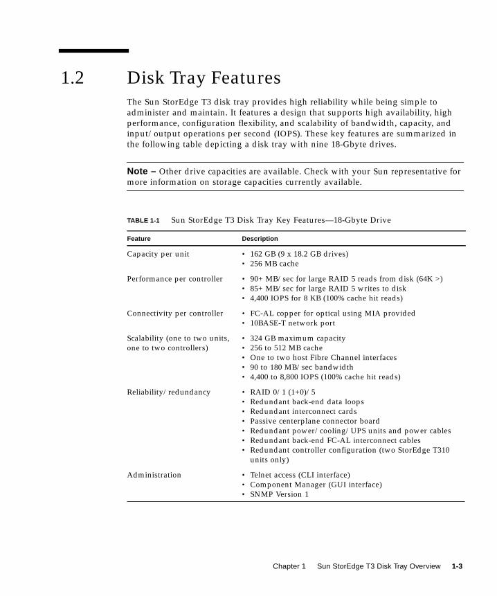

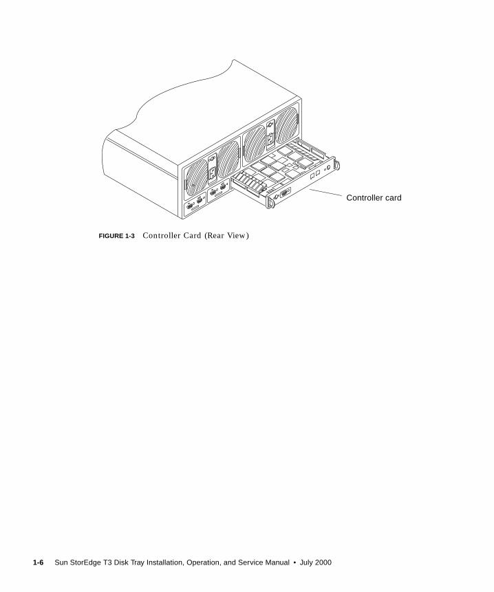


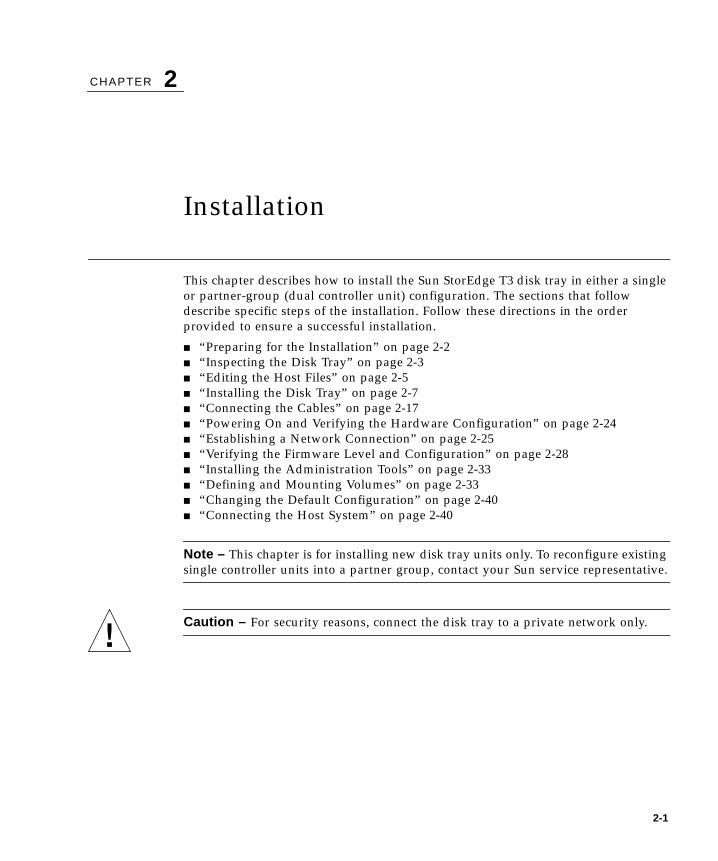


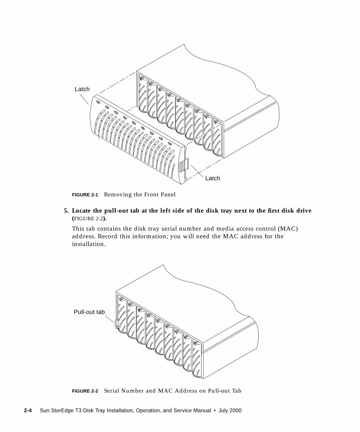


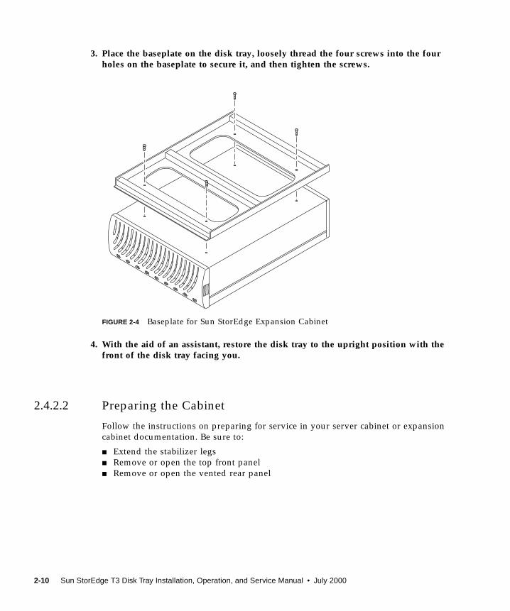


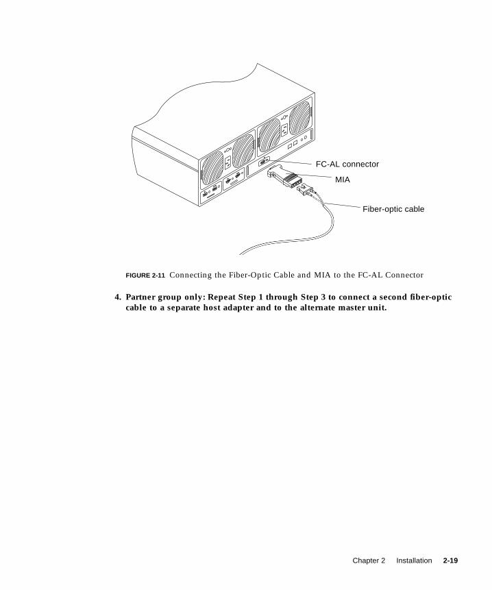


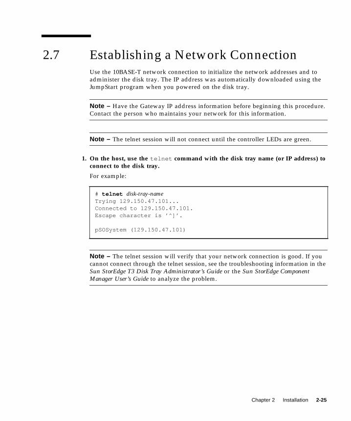


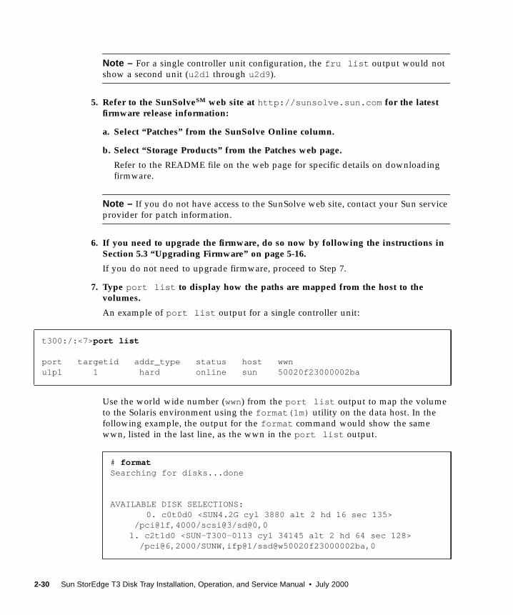


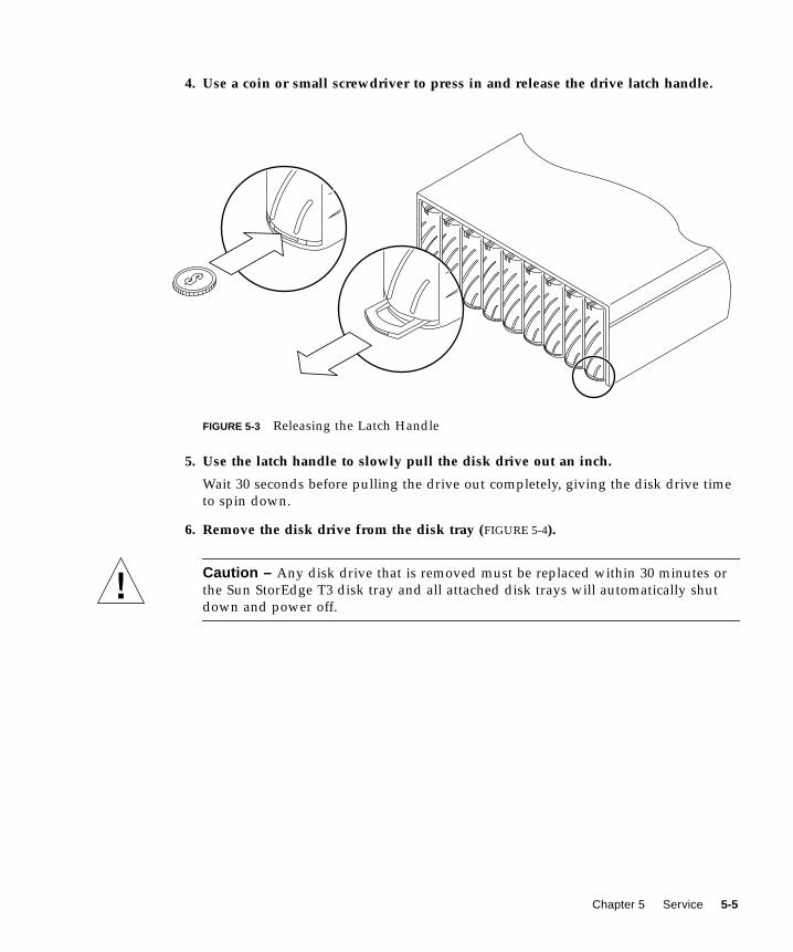

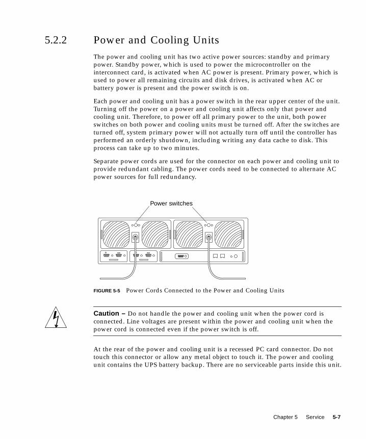

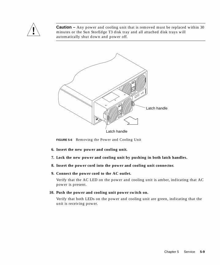


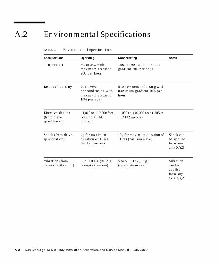


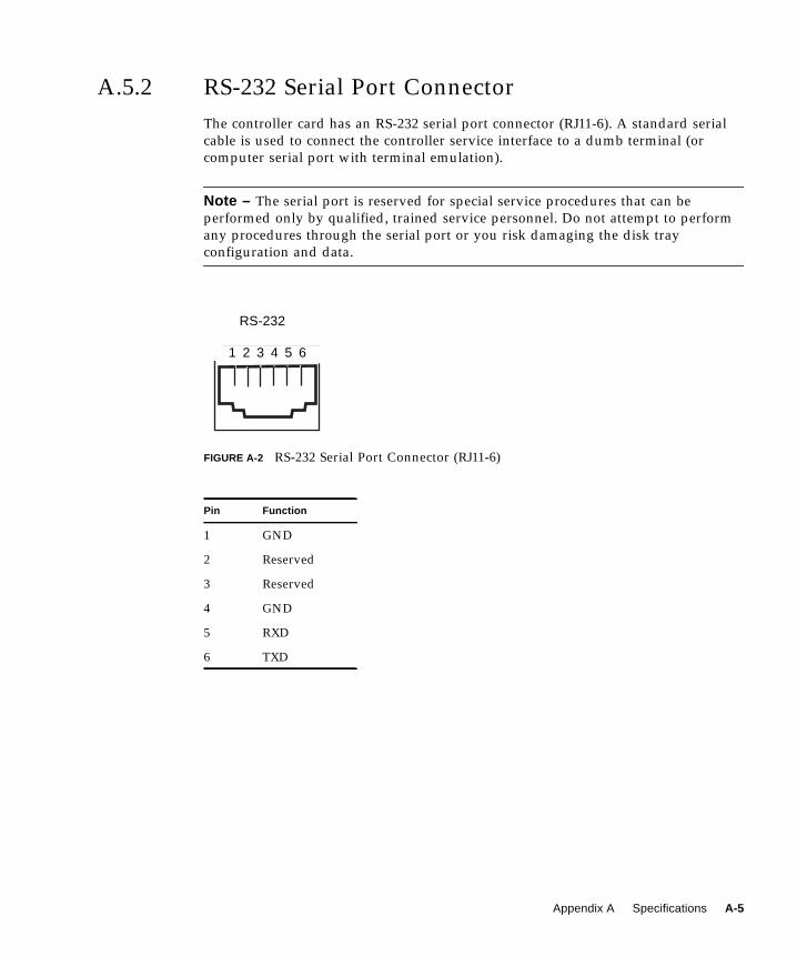

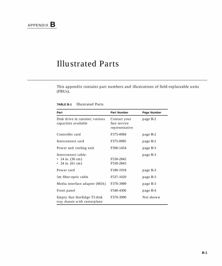


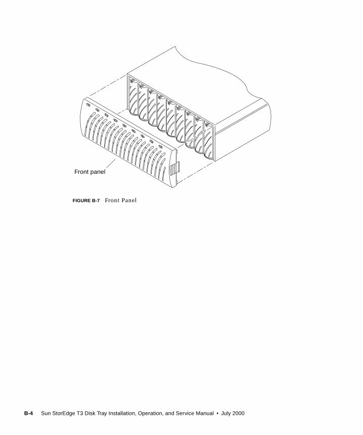


![0) · 2016. 7. 8. · x\hsp[`th`]hy`klwlukpunvu svjh[pvu ;opz^psshhlj[Äuhs lhkpunz ... pj /\tpjhjpk)sluk-sv^ly luohujly t3 t3 t3 t3 t3 t3 t3 t3 t3 t3 t3 t3 t3 t3 t3 t3 t3 t3 t3 t3](https://static.documents.pub/doc/80x56/60d98d4a31005a4c8d3c5fa4/0-2016-7-8-xhspthhyklwlukpunvu-svjhpvu-opzpsshhljuhs-lhkpunz-.jpg)


