29
10’ Octagon Cedar Gazebo Assembly Instructions Toll Free: 866.768.8465 Hours: 9-5 Monday-Friday EST © Suncast Corporation www.HomePlaceStructures.com Package ships as shown
10’ Octagon Cedar GazeboAssembly Instructions
Toll Free: 866.768.8465Hours: 9-5 Monday-Friday EST
© Suncast Corporation
www.HomePlaceStructures.com
Package ships as shown
10’ Cedar GazeboAssembly Instructions
© Suncast Corporation
revised 06/22/09
Please read through the entire manual before starting!
Note: It is very important that you have a firm, level site for the structure.
When using tools and ladders, always follow manufacturer’s recommended safety guidelines!
Tools Needed:
Sharp Utility Knife5/8” Socket
Socket Wrench5/8” Wrench
Hammer StaplerCordless Drill
LadderTape MeasureHammer
Flathead ScrewdriverLevel
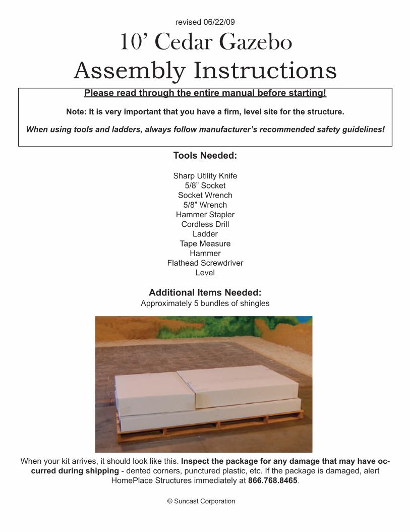
Additional Items Needed:Approximately 5 bundles of shingles
When your kit arrives, it should look like this. Inspect the package for any damage that may have oc-curred during shipping - dented corners, punctured plastic, etc. If the package is damaged, alert
HomePlace Structures immediately at 866.768.8465.

page 01© Suncast Corporation
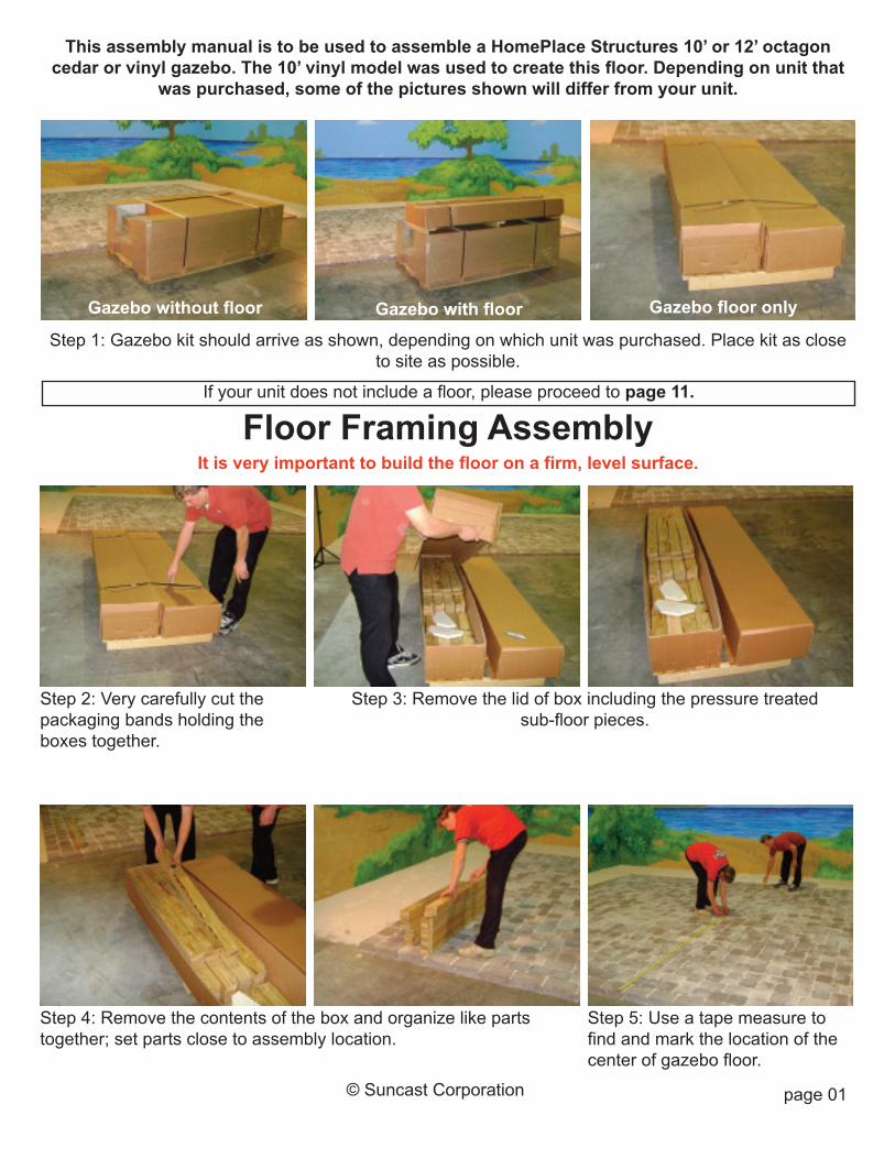
Step 1: Gazebo kit should arrive as shown, depending on which unit was purchased. Place kit as closeto site as possible.
Step 3: Remove the lid of box including the pressure treatedsub-floor pieces.
Step 2: Very carefully cut thepackaging bands holding theboxes together.
Step 4: Remove the contents of the box and organize like partstogether; set parts close to assembly location.
Step 5: Use a tape measure tofind and mark the location of thecenter of gazebo floor.
Gazebo with floorGazebo without floor
If your unit does not include a floor, please proceed to page 11.
Floor Framing AssemblyIt is very important to build the floor on a firm, level surface.
Gazebo floor only
This assembly manual is to be used to assemble a HomePlace Structures 10’ or 12’ octagoncedar or vinyl gazebo. The 10’ vinyl model was used to create this floor. Depending on unit that
was purchased, some of the pictures shown will differ from your unit.

page 02© Suncast Corporation
Step 7: Use the mark from step 5 and lay out double floor joists mak-ing sure to keep notched end up and towards center as shown.
Step 6: Locate the double floorjoists with notch cut at one end.
Step 8: Lay out the eight perimeter band boards as shown.
Step 9: Align the edge of the band board with center of the double joist and attach each end using two 3”screws in the pre-drilled holes. Note: It is important that the top edges of the band board and joist
are aligned flush.
page 03© Suncast Corporation
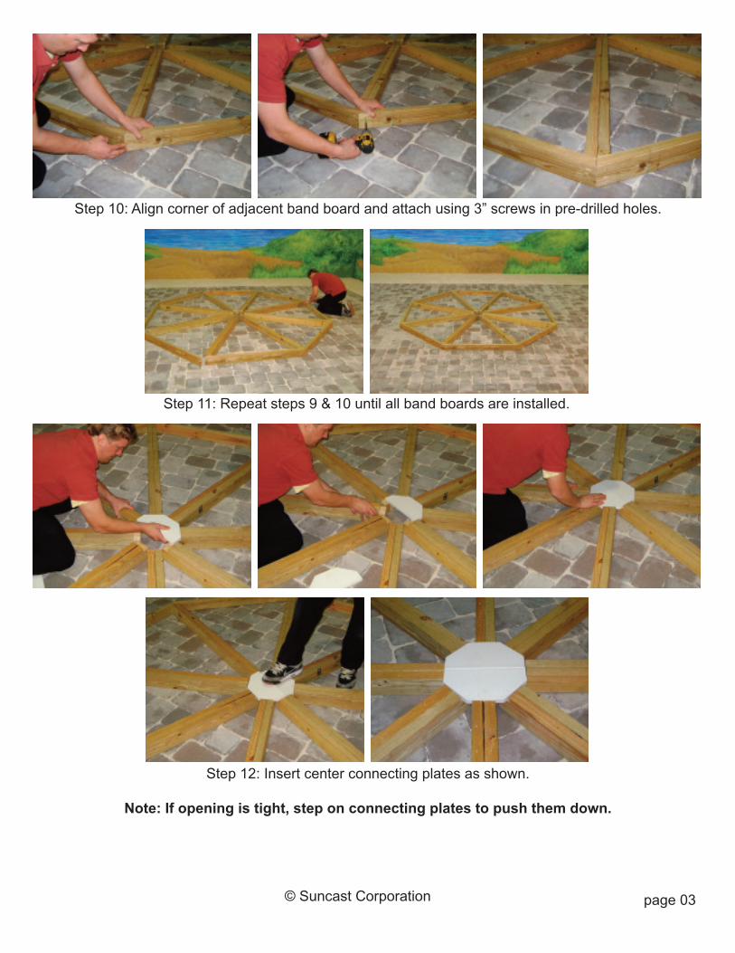
Step 10: Align corner of adjacent band board and attach using 3” screws in pre-drilled holes.
Step 11: Repeat steps 9 & 10 until all band boards are installed.
Step 12: Insert center connecting plates as shown.
Note: If opening is tight, step on connecting plates to push them down.
page 04© Suncast Corporation
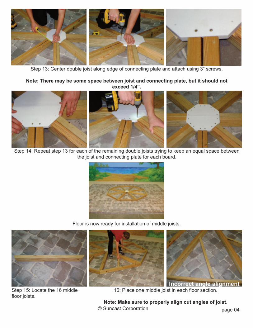
Step 13: Center double joist along edge of connecting plate and attach using 3” screws.
Note: There may be some space between joist and connecting plate, but it should notexceed 1/4”.
Step 14: Repeat step 13 for each of the remaining double joists trying to keep an equal space betweenthe joist and connecting plate for each board.
Floor is now ready for installation of middle joists.
16: Place one middle joist in each floor section.
Note: Make sure to properly align cut angles of joist.
Step 15: Locate the 16 middlefloor joists.
Incorrect angle alignment

page 05© Suncast Corporation
Step 17: Arrange middle floor joists to match pattern shown in picture.
Step 19: Attach band board to middle joist using 3” screws inpre-drilled holes.
Step 18: Align joist with pre-drilledholes in band board.
Step 20: Attach middle joists to double joist using two 3” screwsas shown.
Step 21: Repeat steps 18-20 forthe remaining middle joists.
page 06© Suncast Corporation
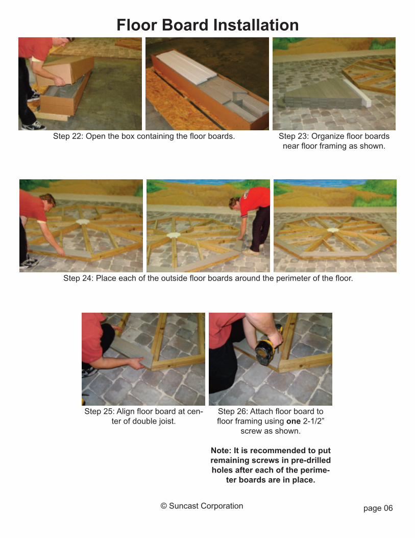
Step 22: Open the box containing the floor boards. Step 23: Organize floor boardsnear floor framing as shown.
Step 24: Place each of the outside floor boards around the perimeter of the floor.
Step 26: Attach floor board tofloor framing using one 2-1/2”
screw as shown.
Note: It is recommended to putremaining screws in pre-drilledholes after each of the perime-
ter boards are in place.
Step 25: Align floor board at cen-ter of double joist.
Floor Board Installation

page 07© Suncast Corporation
Step 30: Repeat steps 25-28 and install adjacent floor board; attach using one 2-1/2” screw ateach end.
Step 31: Install remaining perimeter floor boards repeating steps 25-29.
Step 27: Align opposite end ofboard with center of double joist.
Step 28: Make sure the overhangis consistent along the entire
edge of board.
Step 29: Attach floor board usingone 2-1/2” screw as shown.

page 08© Suncast Corporation
Step 32: Lay out the next complete row of floor boards before attaching any.
Step 34: Attach boards to floor joists using 2-1/2” screws.Step 33: Align boards with edgesof floor joists.
Note: There should be a 1/8”-1/4”space between the rows.
Step 36: Attach floor boards to middle joist.Step 35: Pre-drill one 3/16” holeabove middle floor joist.
Step 37: Repeat steps 33-36 for remainder of floor boards in that row.

page 09© Suncast Corporation
Step 38: Repeat steps 32-37 for each remaining row of floor boards.
Step 39: Install center floor pieces as shown.
Step 40: Attach middle floorboards to sub-floor using 2-1/2”screws through pre-drilled holes.
Note: The center board may re-quire additional force in order to
make it fit.
Floor board installation iscomplete.

page 10© Suncast Corporation
Step 41: Slide the first band board trim piece in place and align atcenter of floor corners.
Band Board Trim Installation
Step 43: Attach trim board to sub-floor using 1-1/2” screws in pre-drilled holes.
Step 44: Align adjacent trim piece and attach repeating steps 41 & 42.
Step 42: Make sure trim piece isup tight against bottom of floor
board.
Step 45: Repeat steps 41-44 around perimeter of gazebo.

page 11© Suncast Corporation
Step 2: Locate the desired loca-tion for the center of the floor.
Step 1: Place package as close toassembly site as possible.
Step 4: Remove and organize the parts as shown.
Step 3: Remove the railing and spindle boxes from the package.
Unpack Railing Boxes
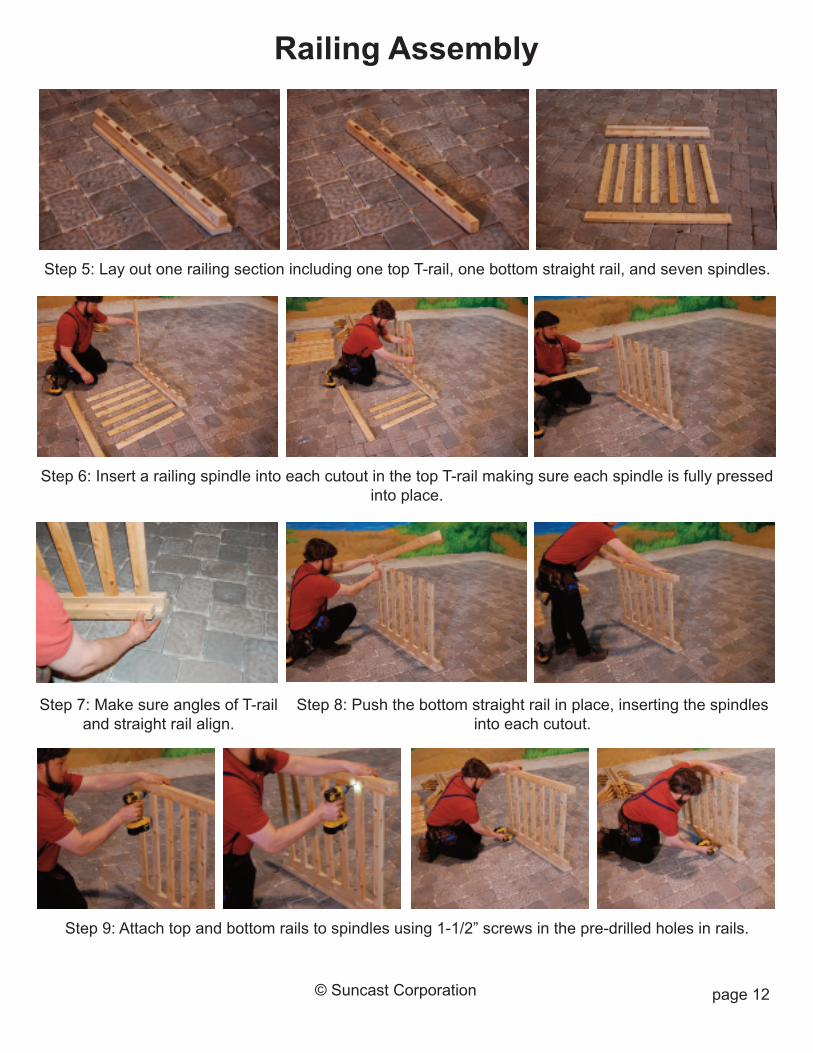
Step 5: Lay out one railing section including one top T-rail, one bottom straight rail, and seven spindles.
Step 8: Push the bottom straight rail in place, inserting the spindlesinto each cutout.
Step 7: Make sure angles of T-railand straight rail align.
Step 6: Insert a railing spindle into each cutout in the top T-rail making sure each spindle is fully pressedinto place.
Step 9: Attach top and bottom rails to spindles using 1-1/2” screws in the pre-drilled holes in rails.
Railing Assembly
page 12© Suncast Corporation

page 13© Suncast Corporation
Step 10: Repeat steps 5-9 for the remaining six railing sections.
Step 11: Locate the post box; remove and organize parts.
Step 12: Each post section includes one left post without rafter bracket, one post with rafter bracket, onebottom railing section, and one top brace section.

Step 13: Lay out one complete post and railing section as shown.
Top Brace Section
Bottom Railing Section
Right Post (withrafter bracket)
Left Post (norafter bracket)
Step 15: Make sure the right postincludes a rafter bracket.
Step 14: Make sure short point ofposts is against the ground.
Step 16: Locate the three spacerblocks included in the package.
Step 17: Insert two spacer blocks under the bottom railing section. Step 18:Use the remaining spacerblock to space the bottom of rail-ing from the bottom of the post.
Post Section Assembly

Step 19: Use the clamp to keepthe spacer block in place.
Step 22: Repeat steps 19-21 on opposite side of section.Step 21: Attach post to top T-railusing two 2-1/2” screws in the
pre-drilled holes.
Step 20: Fasten post to bottom railing section using 2-1/2” screws inpre-drilled holes. To properly align post and railing section, push post
and railing section firmly against hard, flat surface.
Step 23: Use the spacer blocks to align the brace section.
Step 24: Attach the post to the top brace section using four 2-1/2” screws in the pre-drilled holesas shown.
page 15© Suncast Corporation
page 16© Suncast Corporation
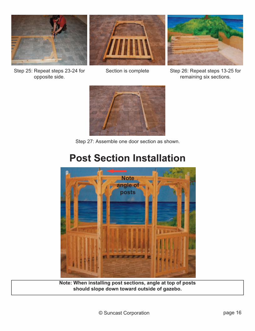
Step 27: Assemble one door section as shown.
Step 25: Repeat steps 23-24 foropposite side.
Section is complete Step 26: Repeat steps 13-25 forremaining six sections.
Post Section Installation
Note: When installing post sections, angle at top of postsshould slope down toward outside of gazebo.
Noteangle of
posts
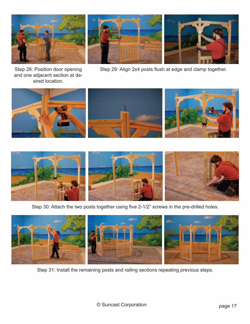
page 17© Suncast Corporation
Step 30: Attach the two posts together using five 2-1/2” screws in the pre-drilled holes.
Step 28: Position door openingand one adjacent section at de-
sired location.
Step 29: Align 2x4 posts flush at edge and clamp together.
Step 31: Install the remaining posts and railing sections repeating previous steps.
page 18© Suncast Corporation
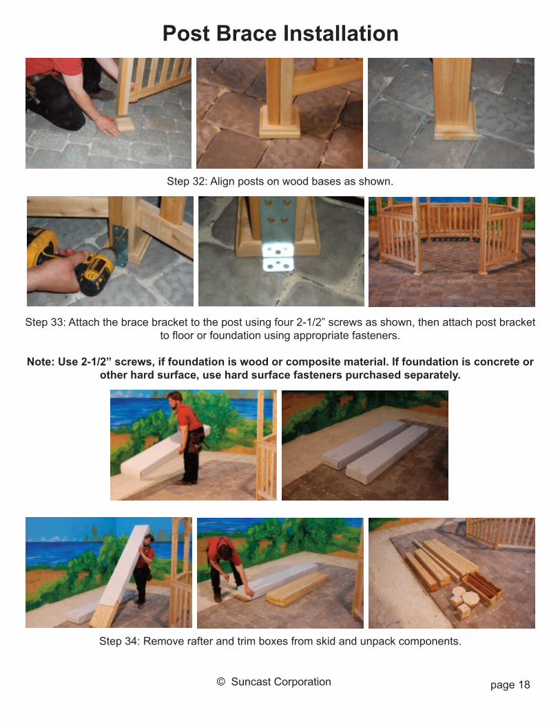
Step 34: Remove rafter and trim boxes from skid and unpack components.
Post Brace Installation
Step 33: Attach the brace bracket to the post using four 2-1/2” screws as shown, then attach post bracketto floor or foundation using appropriate fasteners.
Note: Use 2-1/2” screws, if foundation is wood or composite material. If foundation is concrete orother hard surface, use hard surface fasteners purchased separately.
Step 32: Align posts on wood bases as shown.

page 19© Suncast Corporation
Step 37: Insert rafter bracket between double rafters and align holes.
Step 39: Install opposite rafter repeating steps 37-38.
Step 35: Place a step ladder inthe center of the gazebo.
Step 36: Prepare roof bolts by putting a nut and washer on one endof the bolt as shown.
Step 38: Slide roof bolt through rafters and rafter bracket; put a washer and nut on the opposite end ofthe bolt and tighten acorn nuts by hand.
Note: Do not use tools to tighten nuts at this time (wait until step ??).
Rafter Installation
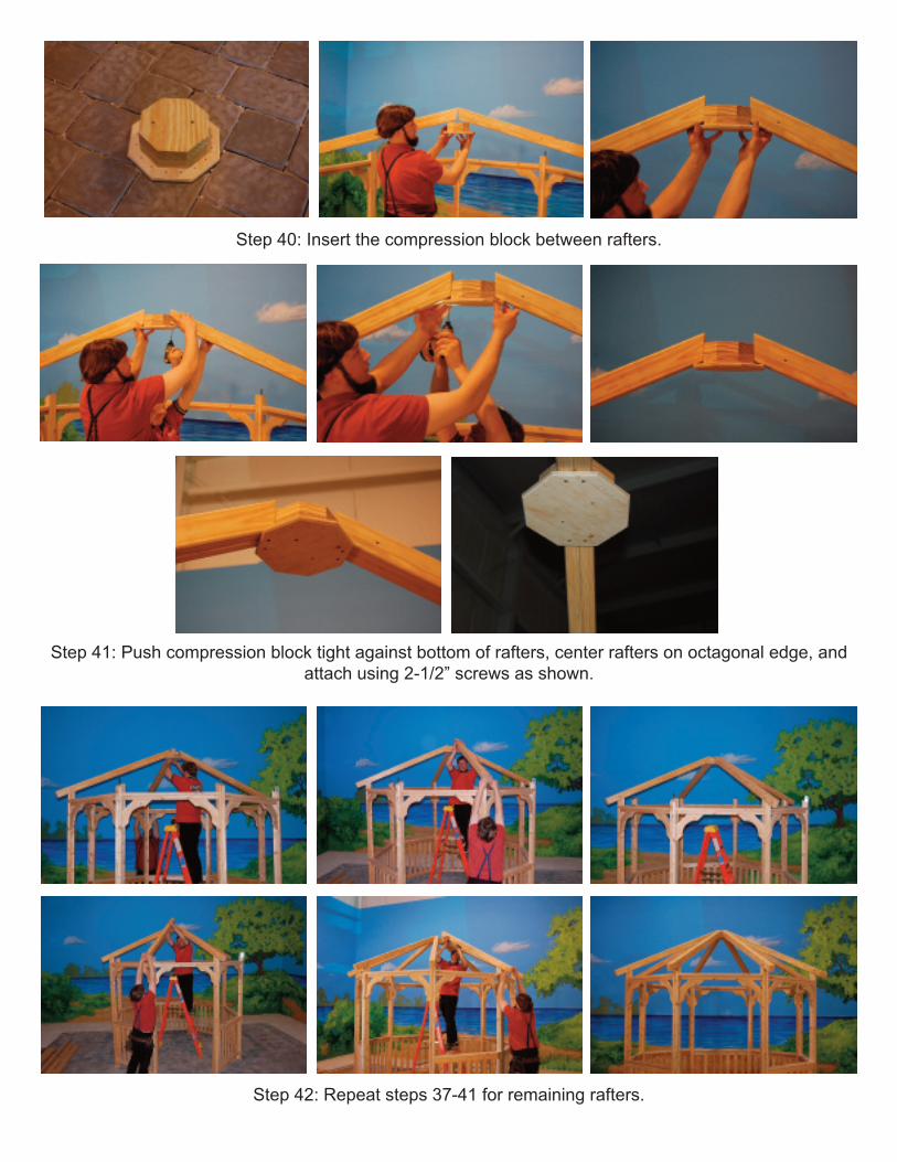
Step 40: Insert the compression block between rafters.
Step 42: Repeat steps 37-41 for remaining rafters.
Step 41: Push compression block tight against bottom of rafters, center rafters on octagonal edge, andattach using 2-1/2” screws as shown.

page 21© Suncast Corporation
Step 43: Align the band board flush with bottom of rafter and at the center of the double rafter splice.
Step 44: Attach the board to the rafter using two 2-1/2” screws through the pre-drilled holes.
Roof Band Board Installation
Step 45: Align and attach opposite end of rafter repeating steps 43 and 44.
Note: If the band board is long, or short, the roof can be adjusted by pulling the top of the post out andpushing the rafter in, or vice versa.
Step 46: Align and attach the adjacent band board repeating previous steps.
page 22© Suncast Corporation
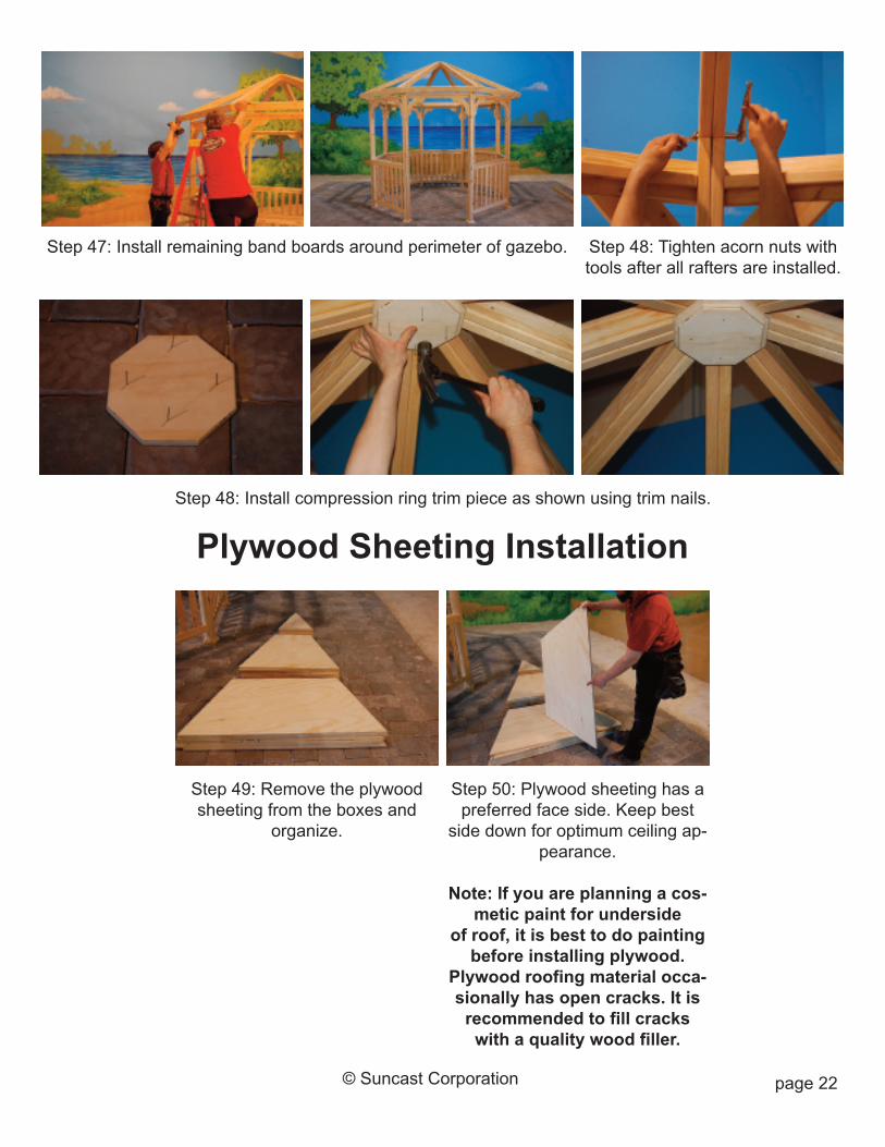
Step 48: Tighten acorn nuts withtools after all rafters are installed.
Step 47: Install remaining band boards around perimeter of gazebo.
Step 48: Install compression ring trim piece as shown using trim nails.
Step 49: Remove the plywoodsheeting from the boxes and
organize.
Plywood Sheeting Installation
Step 50: Plywood sheeting has apreferred face side. Keep best
side down for optimum ceiling ap-pearance.
Note: If you are planning a cos-metic paint for underside
of roof, it is best to do paintingbefore installing plywood.
Plywood roofing material occa-sionally has open cracks. It isrecommended to fill crackswith a quality wood filler.

page 23© Suncast Corporation
Step 51: Align the bottom plywood sheet flush along bottom edge of face board and centered betweenthe double rafters; attach the plywood to the rafters using ten 2” screws.
Step 52: Align and attach the next plywood sheet using six 2” screws.
Step 54: Repeat steps 51-53 for the remaining roof sections.
Step 53: Install the remaining ply-wood sheet using three 2”
screws.

Step 55: Use the C-clamp to align top of face board flush with top ofplywood and at center edge of corner splice.
Step 56: Attach the face board using 2” trim nails.
Face Board Installation
Step 57: Continue installing face board around perimeter of gazebo.
page 24© Suncast Corporation
page 25© Suncast Corporation
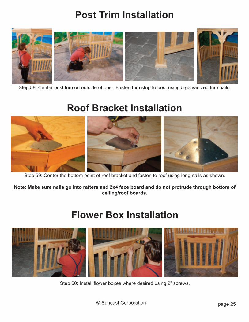
Step 58: Center post trim on outside of post. Fasten trim strip to post using 5 galvanized trim nails.
Step 59: Center the bottom point of roof bracket and fasten to roof using long nails as shown.
Note: Make sure nails go into rafters and 2x4 face board and do not protrude through bottom ofceiling/roof boards.
Post Trim Installation
Step 60: Install flower boxes where desired using 2” screws.
Roof Bracket Installation
Flower Box Installation

Toll Free: 866.768.8465Hours: 9-5 Monday-Friday EST
www.HomePlaceStructures.com
YOUR GAZEBO IS NOW READY FOR SHINGLES!Install shingles following shingle manufacturer’s recommendations.
Note: Plywood roof is 5/8” thick, do not use roof fasteners that will protrude through bottom ofplywood. Double check under roof after installing first shingle to ensure fasteners do not
protrude through.
Plywood roof material occasionally has open cracks. It is recommended to fill cracks with aquality wood filler.
Untreated cedar exposed to the elements will turn light grey in color. To keep cedar wood looking freshand vibrant, apply exterior sealer/stain within first two weeks of exposure and at least one time
each year.
Call the number below with any questions regarding your unit.


